EP4510425A1 - Stator core comprising cooling channels in a motor of a household appliance - Google Patents
Stator core comprising cooling channels in a motor of a household appliance Download PDFInfo
- Publication number
- EP4510425A1 EP4510425A1 EP24184937.1A EP24184937A EP4510425A1 EP 4510425 A1 EP4510425 A1 EP 4510425A1 EP 24184937 A EP24184937 A EP 24184937A EP 4510425 A1 EP4510425 A1 EP 4510425A1
- Authority
- EP
- European Patent Office
- Prior art keywords
- lamination
- hole
- stator
- channel
- cavity channel
- Prior art date
- Legal status (The legal status is an assumption and is not a legal conclusion. Google has not performed a legal analysis and makes no representation as to the accuracy of the status listed.)
- Pending
Links
Images





Classifications
-
- H—ELECTRICITY
- H02—GENERATION; CONVERSION OR DISTRIBUTION OF ELECTRIC POWER
- H02K—DYNAMO-ELECTRIC MACHINES
- H02K1/00—Details of the magnetic circuit
- H02K1/06—Details of the magnetic circuit characterised by the shape, form or construction
- H02K1/12—Stationary parts of the magnetic circuit
- H02K1/14—Stator cores with salient poles
- H02K1/146—Stator cores with salient poles consisting of a generally annular yoke with salient poles
-
- H—ELECTRICITY
- H02—GENERATION; CONVERSION OR DISTRIBUTION OF ELECTRIC POWER
- H02K—DYNAMO-ELECTRIC MACHINES
- H02K1/00—Details of the magnetic circuit
- H02K1/06—Details of the magnetic circuit characterised by the shape, form or construction
- H02K1/12—Stationary parts of the magnetic circuit
- H02K1/18—Means for mounting or fastening magnetic stationary parts on to, or to, the stator structures
- H02K1/185—Means for mounting or fastening magnetic stationary parts on to, or to, the stator structures to outer stators
-
- H—ELECTRICITY
- H02—GENERATION; CONVERSION OR DISTRIBUTION OF ELECTRIC POWER
- H02K—DYNAMO-ELECTRIC MACHINES
- H02K1/00—Details of the magnetic circuit
- H02K1/06—Details of the magnetic circuit characterised by the shape, form or construction
- H02K1/12—Stationary parts of the magnetic circuit
- H02K1/20—Stationary parts of the magnetic circuit with channels or ducts for flow of cooling medium
-
- H—ELECTRICITY
- H02—GENERATION; CONVERSION OR DISTRIBUTION OF ELECTRIC POWER
- H02K—DYNAMO-ELECTRIC MACHINES
- H02K9/00—Arrangements for cooling or ventilating
- H02K9/02—Arrangements for cooling or ventilating by ambient air flowing through the machine
Definitions
- Embodiments of the present invention relate to the technical field of motors, and specifically, to a stator for a motor, a motor, and a household appliance.
- a stator is one of key components of a motor. It is a major part of a magnetic circuit and is configured to mount a stator winding. During operation of the motor, a stator core is subjected to a combined effect of a mechanical force, thermal stress, and an electromagnetic force. Therefore, temperature rise of the stator core plays a crucial role for safe and stable operation of the motor.
- the stator with poor heat dissipation performance causes an overall temperature of the motor to be excessively high, and consequently, indicators of the motor such as working efficiency and a power density are adversely affected.
- heat dissipation of the stator of the motor is mainly implemented through a surface of the stator that is not covered by a housing. Because a surface of an exposed part is generally flat and has a small surface area, a heat dissipation effect of the stator is poor. Even if a heat dissipation rib is additionally arranged on an end cap of the motor, an effect of accelerating dissipation of heat inside the stator is limited.
- An objective of embodiments of the present invention is to provide a stator for a motor, a motor, and a household appliance that are improved.
- an embodiment of the present invention provides a stator for a motor, including: an iron core, including at least one lamination unit arranged in an axial direction of the stator; and at least one cavity channel, formed inside the lamination unit, where an inlet and an outlet that are in communication with each cavity channel are respectively formed on outer surfaces of the lamination unit, and in the axial direction of the stator, the outlet and the inlet have a height difference.
- a heat dissipation surface is formed on an outer surface, and heat inside the stator needs to be radiated to the surface to eventually be dissipated, and heat dissipation efficiency is low.
- the solution of the present disclosure can improve heat dissipation performance of the stator. This helps reduce a temperature of the motor and improve efficiency and a power density of the motor.
- a cavity channel of a three-dimensional spatial structure is formed inside the iron core of the stator, to increase a heat-dissipation surface area of the lamination. Further, there is a height difference between the inlet and the outlet of the cavity channel in the axial direction of the stator, so that air convection is formed.
- the stator with better heat dissipation performance can reduce the overall temperature of the motor, and improve the efficiency and a power density, for example, a maximum output capability of the motor.
- stator in this embodiment can greatly reduce the temperature of the motor, thereby reducing energy consumption of the motor, improving efficiency, and increasing power density of the motor, so that the motor with the same size has higher output.
- inlets and outlets that are in communication with the same cavity channel are respectively formed on outer surfaces on different sides of the lamination unit. Therefore, a length of the cavity channel meandered inside the iron core may be increased, to increase the heat dissipation surface area, thereby further facilitating heat dissipation.
- the lamination unit includes a plurality of laminations, a hole portion is formed in each lamination, and the hole portion is suitable for forming a part of the cavity channel. Therefore, the cavity channel may be formed in the iron core by using a simple lamination process. A production process is simple and easy to implement, and manufacturing costs are low. Further, openings are provided at appropriate positions on each lamination to form the hole portion, and after the plurality of laminations are finally stacked, a channel of a spatial structure may be formed in the iron core of the stator to facilitate heat dissipation. Shapes and structures of the laminations may be the same or different, so that the design of the cavity channel in this embodiment can be flexibly adapted to the iron core of the stator of various structural designs.
- the lamination unit includes a plurality of laminations in the same shape, where the plurality of laminations sequentially are rotated by a preset angle to stack into the lamination unit, a plurality of hole portions arranged in a circumferential direction of the stator are formed in each lamination, and a plurality of hole portions respectively formed in every two adjacent laminations are penetrated in the axial direction of the stator, to form a plurality of cavity channels. Therefore, the plurality of laminations with the same opening layout are rotated and stacked, so that the iron core of the stator with the plurality of cavity channels is manufactured, and the manufacturing process is simple and costs are low.
- a channel of a spatial structure is formed on the iron core of the stator after the plurality of laminations of the same design are rotated by an angle, to facilitate heat dissipation. Because opening layouts of the openings on each lamination is the same, the entire iron core can be produced by developing a single mold. This reduces opening costs and process complexity.
- the lamination unit includes a first lamination, a second lamination, a third lamination, and a fourth lamination that are sequentially arranged in the axial direction of the stator, a first hole, a second hole, a third hole, and a fourth hole that are sequentially arranged in the circumferential direction of the stator are formed in the laminations, and the at least one cavity channel includes a first cavity channel, a second cavity channel, a third cavity channel, and a fourth cavity channel, where every two of the first hole of the first lamination, the second hole of the second lamination, the third hole of the third lamination, and the fourth hole of the fourth lamination are penetrated in the axial direction of the stator to form the first cavity channel, every two of the second hole of the first lamination, the third hole of the second lamination, the fourth hole of the third lamination, and the first hole of the fourth lamination are penetrated in the axial direction of the stator to form the second cavity channel, every two of the third hole of the first lamination, the third hole
- the single lamination unit has four cavity channels distributed in the circumferential direction of the stator, and each cavity channel penetrates through at least a part of the interior of the lamination unit in the axial direction of the stator, so that heat inside the iron core can naturally flow from the inlet on the lower side to the outlet on the upper side/side surface along the cavity channel, and the heat is quickly dissipated to the outside of the iron core.
- projections of the hole portions formed in the adjacent laminations and suitable for forming the cavity channel at least partially overlap in the axial direction of the stator. Therefore, it is ensured that after the plurality of laminations are stacked, the front and rear hole portions remain in communication, to form a through channel inside the iron core of the stacked stator.
- the projections of the hole portions formed in at least two adjacent laminations completely overlap in the axial direction of the stator.
- the surface area of the interior of the cavity channel is larger. This increases a flow speed of an airflow in the cavity channel, and further improves the heat dissipation efficiency.
- a cross-sectional area of a segment of the cavity channel is increased. Because the flow speed of the airflow in the cavity channel is slow due to a viscosity effect near a wall of the cavity channel, the increased cross-sectional area is beneficial for increasing the flow speed of the airflow in the segment of the cavity channel.
- the lamination unit of the stator in this embodiment is used, and the iron core may be obtained by stacking n types of laminations as one cycle. A number of pieces of each type of lamination is more, where n is an integer greater than or equal to 2.
- the cavity channel rotationally extends in the circumferential direction of the stator while extending toward the interior of the iron core in the axial direction of the stator. This helps increase the length of the cavity channel extending inside the iron core in a meandering manner, to optimize a heat dissipation effect, and improve balance of heat dissipation at various positions of the iron core.
- hole portions formed in the first and last laminations in the lamination unit are in communication with edges of respective laminations where the hole portions are located. In this way, it is ensured that the inlet and the outlet of the cavity channel of the lamination unit located in the middle are reliably in communication with the outside of the iron core, to provide a channel for gas convection.
- a number of the plurality of laminations included in the lamination unit is related to a size of hole portions formed in each lamination and an overlapping area of hole portions formed in adjacent laminations in the axial direction of the stator. Therefore, a number of laminations included in a minimum repeating unit is properly designed according to a size of an opening on each lamination and an overlapping degree of openings on adjacent laminations. This helps arrange as many cavity channels as possible by using a space on the iron core to a maximum extent, to obtain a better heat dissipation effect.
- the at least one cavity channel includes at least one channel group arranged in a circumferential direction of the stator, where each channel group includes at least one first channel arranged in the axial direction of the stator. Therefore, at least one channel group is distributed along the circumferential direction of the stator, and a first channel in each channel group penetrates through at least a part of the iron core along the axial direction of the stator, so that heat inside the iron core can naturally flow from a lower inlet of each first channel to an upper outlet along the first channel, thereby quickly dissipating heat to the outside of the iron core. Further, for each channel group, a plurality of independent first channels are provided, so that numbers of inlets and outlets can be increased, and the heat dissipation surface area inside the iron core may further be increased, to better improve the heat dissipation performance.
- the at least one channel group includes a first channel group and a second channel group, and in the axial direction of the stator, the second channel group and the first channel group have a height difference, where the outlet in communication with each first channel in the first channel group and the inlet in communication with each first channel in the second channel group are located on an outer surface of the same side of the lamination unit.
- an airflow enters the second channel group through the first channel group and then is finally discharged out of the motor, to increase the length of the cavity channel through which the airflow flows inside the iron core as a whole, and bring more heat out of the iron core as much as possible, thereby further enhancing the heat dissipation effect.
- the cavity channel further includes second channels, and at least some adjacent first channels of the plurality of first channels are in communication with each other through the second channels.
- the heat dissipation surface area inside the iron core may be further increased, to optimize the heat dissipation effect.
- an embodiment of the present invention further provides a motor, including the stator.
- the stator with a better heat dissipation effect is used, so that the motor has less a less power consumption loss and a higher power density.
- an embodiment of the present invention further provides a household appliance, including: a housing; and the motor, arranged in the housing.
- a stator with a better heat dissipation effect is used, so that a motor arranged in the household appliance has less a less power consumption loss and a higher power density. This helps reduce overall power consumption of the household appliance, and better meet an energy-saving environmental requirement.
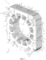
- FIG. 1 is a schematic diagram of a stator 1 for a motor according to a first embodiment of the present invention.
- FIG. 2 is a sectional view of FIG. 1 along an A-A direction. To show a specific structure of a cavity channel 13 inside the stator 1 more clearly, FIG. 2 exemplarily illustrates a region of a cross section.
- a motor may include a stator 1 and a casing (which is not shown and may also be referred to as a base), where the casing is adapted to fix and protect the stator 1.
- the casing may include end caps arranged on two sides of the stator 1 in an axial direction of the stator 1.
- a wire package (which is not shown and may also be referred to as a coil) may be wound on the stator 1 to form a stator winding.
- an axial direction of the stator 1 is denoted as an x-direction
- a circumferential direction is denoted as an r-direction
- a height direction is denoted as a z-direction.
- the height direction of the stator 1 may be parallel to a gravity direction when the stator 1 is stably placed.
- the stable placement may specifically refer to a placement status when the motor is in operation.
- the axial direction (for example, the x-direction) and the circumferential direction (for example, the r-direction) of the stator 1 may be respectively parallel to an axial direction and a circumferential direction of a through hole 10 formed in the stator 1 and configured to accommodate a rotor.
- a plurality of teeth 101 are arranged around the through hole 10 at intervals, where each tooth 101 may be wound with a coil to form the stator.
- the stator 1 for a motor in this embodiment includes an iron core 11, which is also referred to as an iron core of the stator or a stator core.
- the iron core 11 is provided with a through hole 10, and the plurality of teeth 101 are arranged around the through hole 10.
- the iron core 11 may be obtained by stacking a plurality of laminations 121 in the x-direction.
- the iron core 11 includes at least one lamination unit 12 arranged in the axial direction of the stator 1 (for example, the x-direction).
- the lamination unit 12 includes a plurality of laminations 121 arranged in the x-direction.
- the lamination unit 12 may be understood as a minimum repeating unit of the iron core 11.
- a single lamination unit 12 may form the iron core 11, or a plurality of lamination units 12 may be sequentially arranged in the x-direction to form the iron core 11.
- Adjacent lamination units 12 may be closely attached.
- the lamination 121 may be, for example, a silicon steel sheet.
- the stator 1 further includes at least one cavity channel 13, formed inside the lamination unit 12, where an inlet 13a and an outlet 13b that are in communication with each cavity channel 13 are respectively provided on outer surfaces of the lamination unit 12.
- an inlet 13a and an outlet 13b that are in communication with the cavity channel 13 are respectively provided on the outer surfaces of the lamination unit 12, to ensure that air can enter the cavity channel 13 through the inlet 13a, and flow to the outlet 13b along the cavity channel 13 and finally flow out of the iron core 11.
- FIG. 1 exemplarily shows a flow path of gas in a cavity channel 13 by using a curve with a solid arrow.
- the inlet 13a and the outlet 13b are determined according to a placement posture of the stator 1. Specifically, based on a current placement posture of the stator 1, when the motor is in operation, a gas inlet is the inlet 13a, and a gas outlet is the outlet 13b. If a placement direction of the stator 1 changes, positions of the inlet 13a and the outlet 13b in a vertical direction change. For example, after the stator 1 shown in FIG. 1 rotates clockwise by 90 degrees about an axis extending in the x-direction, the outlet 13b originally marked in the figure is located below the inlet 13a. Further, in this case, the original outlet 13b may become the inlet 13a, and the original inlet 13a may become the outlet 13b.
- an outer surface of the at least one lamination unit 12 may jointly form an outer surface 111 of the iron core 11.
- the outlet 13b and the inlet 13a have a height difference in the axial direction of the stator 1 (for example, the x-direction).
- openings in communication with the outside of the iron core 11 are provided at two ends of the cavity channel 13 in an extension direction.
- a lower opening in the z-direction is the inlet 13a, and an upper opening is the outlet 13b.
- an extension path of the cavity channel 13 from the inlet 13a to the outlet 13b may extend in the x-direction and in the z-direction in a meandering manner.
- cavity channels 13 distributed in different regions of the stator 1 in the r-direction are respectively denoted as a first cavity channel 133, a second cavity channel 134, a third cavity channel 135, and a fourth cavity channel 136.
- Flow paths of gas along the cavity channels 13 are respectively shown in the figure (marked by reference numerals of corresponding cavity channels in the figure).
- a cavity channel 13 of a three-dimensional spatial structure is formed inside the iron core 11 of the stator 1, to increase a heat-dissipation surface area of the lamination 121. Further, there is a height difference between the inlet 13a and the outlet 13b of the cavity channel 13 in the axial direction of the stator 1, so that air convection is formed. When an airflow flows along the cavity channel 13, the airflow takes away heat generated in the iron core 11. In this way, heat can be directly dissipated from a heat source to the air, thereby further improving heat dissipation efficiency.
- the stator 1 with better heat dissipation performance can reduce the overall temperature of the motor, and improve the efficiency and a power density, for example, a maximum output capability of the motor.
- the stator 1 When the motor is in operation and the stator 1 generates heat, heat on the stator winding is transferred to the iron core 11, air in the cavity channel 13 is heated and then takes away heat while flowing along the cavity channel 13 from bottom to top, and cold air is automatically added from the bottom.
- a surface area of an interior of each of the plurality of cavity channels 13 is greatly increased, thereby greatly improving the heat dissipation efficiency. Therefore, the stator 1 in this embodiment can greatly reduce the temperature of the motor, thereby reducing energy consumption of the motor, improving efficiency, and increasing power density of the motor, so that the motor with the same size has higher output.
- the inlet 13a and the outlet 13b may be formed on outer surfaces of the lamination unit 12 that are not covered by the casing.
- the plurality of cavity channels 13 may be independent, where each cavity channel 13 is provided with a respective inlet 13a and outlet 13b on outer surfaces of the lamination unit 12.
- an inlet 13a and an outlet 13b that are in communication with the same cavity channel 13 may be respectively arranged on outer surfaces on different sides of the lamination unit 12.
- an inlet 13a and an outlet 13b of the cavity channel 13 may be respectively provided on outer surfaces on adjacent sides of the lamination unit 12.
- the extension path of the cavity channel 13 inside the iron core 11 extends from one side of the iron core 11 to the other adjacent side.
- a plurality of cavity channels 13 are arranged in the iron core 11.
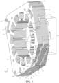
- Some cavity channels 13 (for example, a plurality of cavity channels 13 in a first channel group 131, as shown in FIG. 6 ) are arranged in the x-direction, where an inlet 13a of each cavity channel 13 is located on a lower side of the iron core 11, and an outlet 13b is located on a right side of the iron core 11 from the perspective shown in the figure.
- Some other cavity channels 13 (for example, a plurality of cavity channels 13 in a second channel group 132, as shown in FIG.
- each cavity channel 13 is located on a right side of the iron core 11 from the perspective shown in the figure, and an outlet 13b is located on an upper side of the iron core 11.
- a length of the cavity channel 13 meandered inside the iron core 11 may be increased, to increase the heat dissipation surface area, thereby further facilitating heat dissipation.
- an inlet 13a and an outlet 13b of the same cavity channel 13 are respectively provided on two opposite sides of the lamination unit 12.
- the inlet 13a and the outlet 13b of the same cavity channel 13 may not be on the same plane, where the plane is perpendicular to the x-direction. Therefore, the cavity channel 13 extends at least a distance inside the iron core 11 in the x-direction, to ensure that heat inside the iron core 11 is quickly dissipated through the cavity channel 13.
- the inlet 13a and the outlet 13b may be provided on different laminations 121 of the lamination unit 12, so that the cavity channel 13 extends in the x-direction.
- the lamination unit 12 may include a plurality of laminations 121, where a hole portion 122 may be formed in each lamination 121, and the hole portion 122 is suitable for forming a part of the cavity channel 13.
- the hole portion 122 may run through the lamination 121 in the x-direction.
- a wall of the lamination 121 that forms the hole portion 122 is a part of the cavity channel 13.
- a hole portion 122 formed in the at least one lamination 121 may extend to an edge of the lamination 121, to form an inlet 13a or an outlet 13b.
- the hole portion 122 may also be understood as a notch.
- the cavity channel 13 may be formed in the iron core 11 by using a simple lamination process.
- a production process is simple and easy to implement, and manufacturing costs are low.
- openings are provided at appropriate positions on each lamination 121 to form the hole portion 122, and after the plurality of laminations 121 are finally stacked, a channel of a spatial structure may be formed in the iron core 11 of the stator 1 to facilitate heat dissipation.
- a larger thickness of the lamination 121 in the x-direction indicates a larger cross-sectional area of the part of the cavity channel 13 formed by the openings on the lamination 121.
- a larger aperture of the hole portion 122 indicates a larger cross-sectional area of the part of the cavity channel 13 formed by the hole portion 122.
- shapes and structures of the laminations 121 may be the same or different, so that the design of the cavity channel 13 in this embodiment can be flexibly adapted to the iron core 11 of the stator 1 of various structural designs.
- a notch that is, a hole portion 122 extending to an edge of the first lamination 121 is sequentially provided below a surface of the first lamination 121 in the x-direction, a hole portion 122 is provided on the second lamination 121 and the notch on the first lamination 121 is in communication with an opening on the second lamination 121 in the x-direction, a hole portion 122 is provided on the third lamination 121 and a front end of an opening is in communication with a tail end of the opening on the second lamination 121 in the x-direction, and a notch extending to a side surface is provided on the fourth lamination 121 and an end of the notch is in communication with a tail end of the opening on the third lamination 121.
- every four laminations 121 may form a through channel (that is, a cavity channel 13) of a spatial structure, inlets 13a of the cavity channel 13 are formed on a front surface and a lower side of the lamination unit 12 through the notch of the first lamination 121, and outlets 13b of the cavity channel 13 are formed on side surfaces of the lamination unit 12 through the notch of the fourth lamination 121.
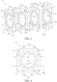
- the lamination unit 12 may include a plurality of laminations 121 in the same shape, where the plurality of laminations 121 sequentially rotate by a preset angle to stack into the lamination unit 12, a plurality of hole portions 122 arranged in a circumferential direction of the stator 1 (for example, the r-direction) may be formed in each lamination 121, and a plurality of hole portions 122 respectively formed in every two adjacent laminations 121 are penetrated in the axial direction of the stator 1 (for example, the x-direction), to form a plurality of cavity channels 13.
- a specific value of the preset angle may be determined based on an included angle (or a spacing) between adjacent hole portions 122 on a single lamination 121.
- a square-shaped lamination 121 is used as an example for exemplary illustration.
- Hole portions 122 are symmetrically arranged at four corners of the square-shaped lamination 121, and correspondingly, the preset angle may be 90 degrees.
- a plurality of laminations 121 of the same design are stacked one by one and rotate clockwise/counterclockwise by 90 degrees, to finally obtain the lamination unit 12 through one-by-one stacking.
- FIG. 3 exemplarily shows an example in which a lamination unit 12 is obtained by rotating a lamination clockwise by 90 degrees each time the lamination is stacked.
- an outer profile of the lamination 121 may be circular, and the plurality of hole portions 122 may be arranged around the through hole 10 at equal intervals in the r-direction.
- the preset angle may be less than a deflection angle of the adjacent hole portions 122 relative to an axis of the through hole 10. Therefore, the plurality of laminations 121 with the same opening layout are rotated and stacked, so that the iron core 11 of the stator 1 with the plurality of cavity channels 13 is manufactured, and the manufacturing process is simple and costs are low.
- a channel of a spatial structure is formed on the iron core 11 of the stator 1 after the plurality of laminations 121 of the same design are rotated by an angle, to facilitate heat dissipation. Because opening layouts of the openings on laminations 121 are the same, the entire iron core 11 can be produced by developing a single mold. This reduces opening costs and process complexity.
- all the hole portions 122 formed on the single lamination 121 are at equal distances from the axis of the through hole 10.
- a pattern enclosed by all hole portions 122 on the lamination 121 is a circle, and may be a concentric circle with the through hole 10.
- a pattern enclosed by all the hole portions 122 formed on the single lamination 121 may be a plurality of concentric circles with the through hole 10.
- a hole portion 122 may be additionally arranged on an outer side of each hole portion 122 in a radial direction of the through hole 10. In this way, layouts of the plurality of hole portions 122 on the lamination 121 and the through hole 10 jointly form three concentric circles.
- the iron core 11 may be obtained by stacking n types of laminations 121 as one cycle, where n is an integer greater than or equal to 2.
- a single cycle is a minimum repeating unit, that is, the single cycle corresponds to a single lamination unit 12.
- a number of pieces of each type of lamination 121 in the single lamination unit 12 may be one, as shown in FIG. 1 to FIG. 4 .
- a number of pieces of each type of lamination 121 in the single lamination unit 12 may be more, as shown in FIG. 5 to FIG. 10 .
- a number of pieces of at least one type of lamination 121 in the single lamination unit 12 may be different from a number of pieces of another type of lamination 121.
- a difference between different types of laminations 121 may be specifically lies in that there is a difference in positions/layouts of openings (for example, hole portions 122 of different types of laminations 121 in the x-direction are not completely in communication).
- the difference in the positions/layouts of the openings may be implemented through laminations 121 of different structural designs, or may be implemented by rotating laminations 121 of the same structural design by a preset angle.
- the lamination unit 12 may include a first lamination 123, a second lamination 124, a third lamination 125, and a fourth lamination 126 that are sequentially arranged in the axial direction of the stator 1 (for example, the x-direction).
- two adjacent laminations 121 may be in surface-to-surface contact.
- each lamination 121 is provided with a first hole 122a, a second hole 122b, a third hole 122c, and a fourth hole 122d that are sequentially arranged in the circumferential direction of the stator 1 (for example, the r-direction).
- the first hole 122a, the second hole 122b, the third hole 122c, and the fourth hole 122d are arranged at equal intervals around the axis of the through hole 10.
- the arrangement at equal intervals may be, for example, that the hole portions 122 are arranged at intervals of 90 degrees.
- first hole 122a and the fourth hole 122d may each extend to an edge of the same side of the lamination 121.
- the at least one cavity channel 13 may include a first cavity channel 133, a second cavity channel 134, a third cavity channel 135, and a fourth cavity channel 136.
- four cavity channels 13 are distributed around the through hole 10 in the r-direction, and extend through the lamination unit 12 in the x-direction.
- the first lamination 123, the second lamination 124, the third lamination 125, and the fourth lamination 126 may each include two laminations 121.
- the first lamination 123, the second lamination 124, the third lamination 125, and the fourth lamination 126 may each include three laminations 121.
- every two of the first hole 122a of the first lamination 123, the second hole 122b of the second lamination 124, the third hole 122c of the third lamination 125, and the fourth hole 122d of the fourth lamination 126 are penetrated in the axial direction of the stator 1 (for example, the x-direction), to form the first cavity channel 133.
- the first cavity channel 133 is located at a lower right corner of the lamination unit 12, where an inlet 13a is provided at a lower side and a front surface of the lamination unit 12, and an outlet 13b is provided at a right side surface of the lamination unit 12.
- the inlet 13a on a lower side and the outlet 13b on an upper side of the first cavity channel 133 are located on different laminations 121.
- the inlet 13a and the outlet 13b are respectively located on the first lamination 123 and the fourth lamination 126.
- every two of the second hole 122b of the first lamination 123, the third hole 122c of the second lamination 124, and the fourth hole 122d of the third lamination 125 are penetrated in the axial direction of the stator 1 (for example, the x-direction), to form the second cavity channel 134.
- the second cavity channel 134 may be located at an upper right corner of the lamination unit 12, where an inlet 13a of the second cavity channel 134 is provided on a front surface of the lamination unit 12 (where the second hole 122b of the first lamination 123 is reused) and is located above the outlet 13b of the first cavity channel 133, and an outlet 13b of the second cavity channel 134 may be provided above the lamination unit 12 (where the fourth hole 122d of the third lamination 125 is reused).
- each of the third hole 122c of the first lamination 123 and the fourth hole 122d of the second lamination 124, and the first hole 122a of the third lamination 125 and the second hole 122b of the fourth lamination 126 may be in communication in the axial direction of the stator 1 (for example, the x-direction), to form two third cavity channels 135.
- the two third cavity channels 135 are each located at an upper left corner of the lamination unit 12 and arranged from front to back in the x-direction.
- An inlet 13a of the front third cavity channel 135 is provided on a left side surface of the lamination unit 12 (where the fourth hole 122d of the second lamination 124 is reused) and is located above an outlet 13b of the fourth cavity channel 136 that is also provided on the left side surface.
- An outlet 13b of the front third cavity channel 135 may be provided on a front surface of the lamination unit 12 (where the third hole 122c of the first lamination 123 is reused).
- An inlet 13a of the rear third cavity channel 135 is provided on a rear surface of the lamination unit 12 (where the second hole 122b of the fourth lamination 126 is reused) and is located above an outlet 13b of the fourth cavity channel 136.
- An outlet 13b of the rear third cavity channel 135 may be provided above the lamination unit 12 (where the first hole 122a of the third lamination 125 is reused).
- the fourth cavity channel 136 may be located at a lower left corner of the lamination unit 12, where an inlet 13a is provided on the rear surface of the lamination unit 12 (where the third hole 122c of the fourth lamination 126 is reused), and an outlet 13b is formed on the left side surface of the lamination unit 12 (where the first hole 122a of the second lamination 124 is reused).
- the single lamination unit 12 has four cavity channels 13 distributed in the circumferential direction of the stator 1, and each cavity channel 13 penetrates through at least a part of the interior of the lamination unit 12 in the axial direction of the stator 1, so that heat inside the iron core 11 can naturally flow from the inlet 13a on the lower side to the outlet 13b on the upper side/side surface along the cavity channel 13, and the heat is quickly dissipated to the outside of the iron core 11.
- the iron core 11 obtained by arranging the plurality of lamination units 12 in the x-direction is provided with inlets 13a and outlets 13b of the cavity channel 13 on four sides (for example, upper and lower and left and right sides from the perspective shown in the figure) in the circumferential direction (for example, the r-direction).
- inlets 13a and outlets 13b of the cavity channel 13 on four sides (for example, upper and lower and left and right sides from the perspective shown in the figure) in the circumferential direction (for example, the r-direction).
- an airflow can flow more omnidirectionally inside the iron core 11 to quickly take away heat inside the iron core 11.
- an inlet 13a and an outlet 13b that are adapted to be provided on side surfaces form a cavity channel 13 in communication with the outside, to achieve heat dissipation.
- adjacent lamination units 12 may jointly form the cavity channel 13. This helps increase a length of the cavity channel 13 extending in the iron core 11, and further improve heat dissipation performance.
- the first hole 122a of the fourth lamination 126 in the front lamination unit 12 may form the second cavity channel 134 together with the second hole 122b of the first lamination 123, the third hole 122c of the second lamination 124, and the fourth hole 122d of the third lamination 125 in the rear lamination unit 12. Therefore, a longer second cavity channel 134 facilitates better heat dissipation.
- the inlet 13a of the second cavity channel 134 may reuse the first hole 122a of the fourth lamination 126 in the front lamination unit 12.
- the inlet 13a of the second cavity channel 134 may be provided on a right side of the iron core 11 from the perspective shown in the figure, and is located above the outlet 13b of the first cavity channel 133 that is also provided on the right side. Therefore, gas flowing out of first cavity channels 133 of the two adjacent lamination units 12 may enter the iron core 11 again through the inlet 13a of the second cavity channel 134. This helps increase a path through which the airflow flows in the iron core 11, thereby improving heat dissipation efficiency.
- the fourth hole 122d of the second lamination 124 and the third hole 122c of the first lamination 123 in the rear lamination unit 12 may form the third cavity channel 135 together with the second hole 122b of the fourth lamination 126 and the first hole 122a of the third lamination 125 in the front lamination unit 12. Therefore, compared with the third cavity channel 135 formed by the hole portions 122 on the two laminations 121 in the foregoing embodiment, the third cavity channel 135 jointly formed by the four laminations 121 in this example is longer, and more heat inside the iron core 11 can be taken away.
- the inlet 13a of the third cavity channel 135 may reuse the fourth hole 122d of the second lamination 124 in the rear lamination unit 12, and the outlet 13b may reuse the first hole 122a of the third lamination 125 in the front lamination unit 12.
- the inlet 13a of the third cavity channel 135 is provided on a left side of the iron core 11 from the perspective shown in the figure and is located above the outlet 13b of the fourth cavity channel 136 that is also provided on the left side, and the outlet 13b of the third cavity channel 135 is provided on the top of the iron core 11 from the perspective shown in the figure.
- gas flowing out of fourth cavity channels 136 of the two adjacent lamination units 12 may enter the iron core 11 again through the inlet 13a of the third cavity channel 135. This helps increase a path through which the airflow flows in the iron core 11, thereby improving the heat dissipation efficiency.
- the fourth hole 122d of the first lamination 123 in the rear lamination unit 12 may form the fourth cavity channel 136 together with the first hole 122a of the second lamination 124, the second hole 122b of the third lamination 125, and the third hole 122c of the fourth lamination 126 in the front lamination unit 12. Therefore, a longer fourth cavity channel 136 facilitates better heat dissipation.
- the inlet 13a of the fourth cavity channel 136 may reuse the fourth hole 122d of the first lamination 123 in the rear lamination unit 12, and the outlet 13b may reuse the first hole 122a of the second lamination 124 in the front lamination unit 12.
- the inlet 13a of the fourth cavity channel 136 is provided on the bottom of the iron core 11 from the perspective shown in the figure, and the outlet 13b is provided on the left side of the iron core 11 from the perspective shown in the figure.
- sizes and positions of a first hole 122a, a second hole 122b, a third hole 122c, and a fourth hole 122d on each lamination 121 are adjusted, so that every two of a second hole 122b of a first lamination 123, a third hole 122c of a second lamination 124, a fourth hole 122d of the third lamination 125, and a first hole 122a of a fourth lamination 126 on the same lamination unit 12 may be in communication in the axial direction of the stator 1 (for example, the x-direction), to form the second cavity channel 134. Therefore, the second cavity channel 134 formed in the single lamination unit 12 fully uses hole portions 122 of all laminations 121, to maximize the length of the cavity channel 13, and increase the heat dissipation surface area inside the iron core 11.
- first hole 122a, the second hole 122b, the third hole 122c, and the fourth hole 122d on the lamination 121 are adjusted, so that two third cavity channels 135 may be penetrated into one cavity channel from front to back.
- the inlet 13a may reuse the third hole 122c of the first lamination 123, and the outlet 13b may reuse the second hole 122b of the fourth lamination 126.
- the casing may avoid a hole portion 122 on a front surface of the lamination 121, to block the inlet 13a and/or the outlet 13b of the cavity channel 13.
- the casing that covers two sides of the lamination unit 12 in the x-direction may avoid the second hole 122b of the first lamination 123, to ensure that the second cavity channel 134 is reliably in communication with the outside.
- openings and/or notches on two adjacent laminations 121 in the x-direction at least partially overlap.
- the first cavity channel 133 is used as an example. Refer to FIG. 2 , FIG. 6 , and FIG. 9 . Projections of the first hole 122a of the first lamination 123 and the second hole 122b of the second lamination 124 in the x-direction overlap end to end, projections of the second hole 122b of the second lamination 124 and the third hole 122c of the third lamination 125 in the x-direction overlap end to end, and projections of the third hole 122c of the third lamination 125 and the fourth hole 122d of the fourth lamination 126 in the x-direction overlap end to end.
- the end-to-end overlapping specifically means that, in a flow direction of an airflow in the cavity channel 13, a tail end of a front hole portion 122 and a front end of a rear hole portion 122 are penetrated from front to back in the x-direction.
- projections of hole portions 122 provided on at least two adjacent laminations 121 in the axial direction of the stator 1 may completely overlap.
- a plurality of laminations 121 in at least one lamination unit 12 in the stator 1 may be obtained by stacking every n types of laminations 121 as one cycle.
- a number of pieces of each type of lamination 121 is more (that is, two or more), where n is an integer greater than or equal to 2.
- a single lamination unit 12 may include two first laminations 123, two second laminations 124, two third laminations 125, and two fourth laminations 126.
- the two first laminations 123, the two second laminations 124, the two third laminations 125, and the two fourth laminations 126 are sequentially stacked in the x-direction.
- a single lamination unit 12 may include three first laminations 123, three second laminations 124, three third laminations 125, and three fourth laminations 126.
- the three first laminations 123, the three second laminations 124, the three third laminations 125, and the three fourth laminations 126 are sequentially stacked in the x-direction.
- the surface area of the interior of the cavity channel 13 is larger. This increases a flow speed of an airflow in the cavity channel 13, and further improves the heat dissipation efficiency. Specifically, considering that a single lamination 121 is thin, positions of the openings on a plurality of adjacent laminations 121 are kept consistent, a cross-sectional area of a segment of the cavity channel 13 is increased. Because the flow speed of the airflow in the cavity channel 13 is slow due to a viscosity effect near a wall of the cavity channel 13, the increased cross-sectional area is beneficial for increasing the flow speed of the airflow in the segment of the cavity channel 13.
- projections of the hole portions 122 that are formed in each lamination 121 included in the lamination unit 12 and that are suitable for forming the same cavity channel 13 may deflect clockwise or anticlockwise in the axial direction of the stator 1.
- the first cavity channel 133 is used as an example. Still refer to FIG. 3 , FIG. 7 , and FIG. 10 .
- Four hole portions 122 namely, the first hole 122a of the first lamination 123, the second hole 122b of the second lamination 124, the third hole 122c of the third lamination 125, and the fourth hole 122d of the fourth lamination 126 sequentially deflect counterclockwise from a lower edge to a right edge of the lamination unit 12 from the perspective shown in the figure.
- the first cavity channel 133 arranged at the lower right corner of the lamination unit 12 extends in the x-direction from a position near the lower side toward the interior of the lamination unit 12, and extends counterclockwise from the perspective shown in the figure.
- the cavity channel 13 rotationally extends in the circumferential direction of the stator 1 (for example, the r-direction) while extending toward the interior of the iron core 11 in the axial direction of the stator 1 (for example, the x-direction). This helps increase the length of the cavity channel 13 extending inside the iron core 11 in a meandering manner, to optimize a heat dissipation effect, and improve balance of heat dissipation at various positions of the iron core 11.
- hole portions 122 formed in the first and last laminations 121 in the lamination unit 12 may be in communication with edges of respective laminations 121 where the hole portions are located.
- hole portions 122 arranged on first and last laminations 121 of the lamination unit 12 extends in an extension direction to an edge of the lamination 121 to form a notch.
- an inlet 13a and an outlet 13b of the cavity channel 13 are provided on side surfaces of the lamination unit 12 around the r-direction.
- openings on first and last laminations 121 of first and last lamination units 12 of the plurality of lamination units 12 may also extend in the extension direction to be in communication with an edge of the lamination 121. Therefore, when the casing covers an outer surface of the first lamination 121 of the first lamination unit 12 and an outer surface of the last lamination 121 of the last lamination unit 12 arranged in the x-direction, a cavity channel 13 on the first and last lamination units 12 can still ensure reliable communication with the outside of the iron core 11.
- a number of the plurality of laminations 121 included in the lamination unit 12 may be related to a size of hole portions 122 formed in each lamination 121 and an overlapping area of hole portions 122 formed in adjacent laminations 121 in the axial direction of the stator 1 (for example, the x-direction).
- a cavity channel 13 penetrating through the lamination unit 12 may be obtained by stacking a smaller number of different types of laminations 121.
- a single lamination unit 12 includes fewer laminations 121.
- a single lamination unit 12 includes more laminations 121.
- a number of laminations 121 included in a minimum repeating unit is properly designed according to a size of an opening on each lamination 121 and an overlapping degree of openings on adjacent laminations 121. This helps arrange as many cavity channels 13 as possible by using a space on the iron core 11 to a maximum extent, to obtain a better heat dissipation effect.
- At least one cavity channel 13 may include at least one channel group 130 arranged in the circumferential direction of the stator 1 (for example, the r-direction).
- Each channel group 130 may include at least one first channel 137 arranged in the axial direction of the stator 1 (for example, the x-direction).
- cavity channels 13 arranged in different regions of the iron core 11 in the r-direction may be divided into different channel groups 130.
- inlets 13a of first channels 137 in the same channel group 130 may be located on the same side of the iron core 11.
- outlets 13b of the first channels 137 in the same channel group 130 may also be located on the same side of the iron core 11.
- inlets 13a of first channels 137 in different channel groups 130 may be located on different sides of the iron core 11.
- outlets 13b of the first channels 137 in the different channel groups 130 may also be located on different sides of the iron core 11.
- the iron core 11 may include four channel groups 130 respectively located at four corners of a rectangular lamination 121, and each channel group 130 includes four first channels 137.
- FIG. 1 shows an example in which four lamination units 12 are stacked in an x-direction
- FIG. 2 shows an internal structure by using three of the lamination units 12 as an example.
- first cavity channels 133 belong to the same channel group 130
- second cavity channels 134 belong to the same channel group 130
- third cavity channels 135 belong to the same channel group 130
- fourth cavity channels 136 belong to the same channel group 130.
- Each of the first cavity channel 133, the second cavity channel 134, the third cavity channel 135, and the fourth cavity channel 136 may be considered as a first channel 137.
- the iron core 11 may include four channel groups 130 respectively located at four corners of a rectangular lamination 121, and each channel group 130 includes two first channels 137.
- first cavity channels 133 belong to the same channel group 130
- second cavity channels 134 belong to the same channel group 130
- third cavity channels 135 belong to the same channel group 130
- fourth cavity channels 136 belong to the same channel group 130.
- Each of the first cavity channel 133, the second cavity channel 134, the third cavity channel 135, and the fourth cavity channel 136 may be considered as a first channel 137.
- the iron core 11 may include two channel groups 130 respectively located at four corners of a rectangular lamination 121, and each channel group 130 includes two first channels 137.
- FIG. 8 shows an example in which two lamination units 12 are stacked in an x-direction
- FIG. 9 shows an internal structure by using one of the lamination units 12 as an example.
- first cavity channels 133 belong to the same channel group 130
- second cavity channels 134 belong to the same channel group 130
- third cavity channels 135 belong to the same channel group 130
- fourth cavity channels 136 belong to the same channel group 130.
- Each of the first cavity channel 133, the second cavity channel 134, the third cavity channel 135, and the fourth cavity channel 136 may be considered as a first channel 137.
- first channel 137 may be formed by providing openings on laminations 121 of the single lamination unit 12.
- the first cavity channel 133 is used as an example.
- Four laminations 121 of the single lamination unit 12 may form one first cavity channel 133.
- the first channel 137 may also be jointly formed by laminations 121 of adjacent lamination units 12.
- the second cavity channel 134 is used as an example.
- the laminations 121 of the adjacent lamination units 12 jointly form one second cavity channel 134.
- At least one channel group 130 is distributed along the circumferential direction of the stator 1 (for example, the r-direction), and a first channel 137 in each channel group 130 penetrates through at least a part of the iron core 11 along the axial direction of the stator 1 (for example, the x-direction), so that heat inside the iron core 11 can naturally flow from a lower inlet 13a of each first channel 137 to an upper outlet 13b along the first channel 137, thereby quickly dissipating heat to the outside of the iron core 11.
- each channel group 130 a plurality of independent first channels 137 are provided, so that numbers of inlets 13a and outlets 13b can be increased, and the heat dissipation surface area inside the iron core 11 may further be increased, to better improve the heat dissipation performance.
- the at least one channel group 130 may include a first channel group 131 and a second channel group 132.
- the second channel group 132 and the first channel group 131 may have a height difference.
- the first channel group 131 may include at least one first cavity channel 133 arranged in the x-direction
- the second channel group 132 may include at least one second cavity channel 134 arranged in the x-direction. In the z-direction, the first channel group 131 may be located below the second channel group 132.
- the first channel group 131 may include at least one fourth cavity channel 136 arranged in the x-direction
- the second channel group 132 may include at least one third cavity channel 135 arranged in the x-direction. In the z-direction, the first channel group 131 may be located below the second channel group 132.
- an outlet 13b in communication with each first channel 137 in the first channel group 131 and an inlet 13a in communication with each first channel 137 in the second channel group 132 may be located on an outer surface of the same side of the lamination unit 12.
- the first channel group 131 includes the first cavity channel 133
- the second channel group 132 includes the second cavity channel 134.
- An outlet 13b of the first channel group 131 is located on a right side of the iron core 11, and an inlet 13a of the second channel group 132 is also located on the right side of the iron core and is located above the outlet 13b of the first channel group 131.
- the outlet 13b of the first channel group 131 may reuse the fourth hole 122d of the fourth lamination 123, and the inlet 13a of the second channel group 132 may reuse the first hole 122a of the fourth lamination 126.
- the first channel group 131 includes a fourth cavity channel 136
- the second channel group 132 includes a third cavity channel 135.
- An outlet 13b of the first channel group 131 is located on a left side of the iron core 11, and an inlet 13a of the second channel group 132 is also located on the left side of the iron core and is located above the outlet 13b of the first channel group 131.
- the outlet 13b of the first channel group 131 may reuse the first hole 122a of the second lamination 124, and the inlet 13a of the second channel group 132 may reuse the fourth hole 122b of the second lamination 124.
- an airflow enters the second channel group 132 through the first channel group 131 and then is finally discharged out of the motor, to increase the length of the cavity channel 13 through which the airflow flows inside the iron core 11 as a whole, and bring more heat out of the iron core 11 as much as possible, thereby further enhancing the heat dissipation effect.
- the cavity channel 13 may further include a second channel 138, and at least some adjacent first channels 137 of the plurality of first channels 137 are in communication with each other through the second channel 138.
- the cavity channel 13 obtained by rotating and stacking the plurality of laminations 121 may further include a second channel 138 extending in the axial direction of the stator 1 (for example, the x-direction).
- first channels 137 in each channel group 130 are in communication through corresponding second channels 138.
- the second channel 138 may be configured to be in communicate with a first channel 137 of adjacent minimum repeating units (for example, lamination units 12).
- a first channel 137 of adjacent minimum repeating units for example, lamination units 12.
- a density of hole portions 122 arranged in the circumferential direction of the stator 1 may be increased, to increase the number of openings on the lamination 121.
- two hole portions 122 may be formed at each corner of the lamination 121, where one of the two hole portions 122 extends to an edge of the lamination 122 in a direction away from the other hole portion.
- the hole portions 122 formed at the four corners may be symmetric vertically and horizontally.
- the hole portion 122 may extend in an arc shape. Further, a radian of the arc may be fitted with a radian of the through hole 10.
- each lamination 121 may be provided with fixing holes 112 spaced apart in the circumferential direction r.
- fixing holes 112 on all laminations 121 included in the lamination unit 12 are penetrated in the x-direction.
- each fixing hole 112 is adapted to fit with a fixing member such as a screw to fix at least one lamination unit 12 into one body.
- each lamination 121 may be provided with mounting holes 113 spaced apart in the circumferential direction r, for mounting an insulating skeleton (not shown). During actual application, the mounting hole 113 may be eliminated.
- An embodiment of the present invention further provides a motor, including the stator 1 shown in any one of the foregoing embodiments shown in FIG. 1 to FIG. 13 .
- the stator 1 with a better heat dissipation effect is used, so that the motor has less a less power consumption loss and a higher power density.
- An embodiment of the present invention further provides a household appliance, including: a housing; and a motor, arranged in the housing, where the motor includes the stator 1 according to any one of the foregoing embodiments shown in FIG. 1 to FIG. 13 .
- the household appliance may be, for example, a refrigerating appliance, a washing machine, a drying machine, or a range hood.
- the refrigerating appliance may include a refrigerator, a freezer, and the like.
- a stator 1 with a better heat dissipation effect is used, so that a motor arranged in the household appliance has less a less power consumption loss and a higher power density. This helps reduce overall power consumption of the household appliance, and better meet an energy-saving environmental requirement.
Landscapes
- Engineering & Computer Science (AREA)
- Power Engineering (AREA)
- Iron Core Of Rotating Electric Machines (AREA)
Abstract
A stator of a motor for an household appliance includes: an iron core (11), including at least one lamination unit (12). All laminations being arranged in axial direction. The core includes at least one cavity channel (13) formed in lamination unit/s. An inlet (13a) and an outlet (13b), being in fluid communication with one cavity channel (13), are formed on an outer peripheral surface of each lamination. The inlet (13a) and outlet (13b) of each cavity channel (13) have in axial direction a height difference, as each cavity channel is spiralling in the iron core (11).
Description
- Embodiments of the present invention relate to the technical field of motors, and specifically, to a stator for a motor, a motor, and a household appliance.
- A stator is one of key components of a motor. It is a major part of a magnetic circuit and is configured to mount a stator winding. During operation of the motor, a stator core is subjected to a combined effect of a mechanical force, thermal stress, and an electromagnetic force. Therefore, temperature rise of the stator core plays a crucial role for safe and stable operation of the motor. The stator with poor heat dissipation performance causes an overall temperature of the motor to be excessively high, and consequently, indicators of the motor such as working efficiency and a power density are adversely affected.
- Currently, heat dissipation of the stator of the motor is mainly implemented through a surface of the stator that is not covered by a housing. Because a surface of an exposed part is generally flat and has a small surface area, a heat dissipation effect of the stator is poor. Even if a heat dissipation rib is additionally arranged on an end cap of the motor, an effect of accelerating dissipation of heat inside the stator is limited.
- An objective of embodiments of the present invention is to provide a stator for a motor, a motor, and a household appliance that are improved.
- Therefore, an embodiment of the present invention provides a stator for a motor, including: an iron core, including at least one lamination unit arranged in an axial direction of the stator; and at least one cavity channel, formed inside the lamination unit, where an inlet and an outlet that are in communication with each cavity channel are respectively formed on outer surfaces of the lamination unit, and in the axial direction of the stator, the outlet and the inlet have a height difference.
- Compared with an existing motor stator, only a heat dissipation surface is formed on an outer surface, and heat inside the stator needs to be radiated to the surface to eventually be dissipated, and heat dissipation efficiency is low. The solution of the present disclosure can improve heat dissipation performance of the stator. This helps reduce a temperature of the motor and improve efficiency and a power density of the motor. Specifically, a cavity channel of a three-dimensional spatial structure is formed inside the iron core of the stator, to increase a heat-dissipation surface area of the lamination. Further, there is a height difference between the inlet and the outlet of the cavity channel in the axial direction of the stator, so that air convection is formed. When an airflow flows along the cavity channel, the airflow takes away heat generated in the iron core. In this way, heat can be directly dissipated from a heat source to the air, thereby further improving heat dissipation efficiency. The stator with better heat dissipation performance can reduce the overall temperature of the motor, and improve the efficiency and a power density, for example, a maximum output capability of the motor.
- Further, natural convection is achieved in the cavity channel by using a self-pulling force of the hot air during rise. An airflow naturally flows in the cavity channel without additionally arranging a driving mechanism to perform air evacuation, thereby improving the heat dissipation efficiency. When the motor is in operation and the stator generates heat, heat on the stator winding is transferred to the iron core, air in the cavity channel is heated and then takes away heat while flowing along the cavity channel from bottom to top, and cold air is automatically added from the bottom. Compared to a heat-dissipation surface area of a conventional iron core of a stator, a surface area of an interior of each of the plurality of cavity channels is greatly increased, thereby greatly improving the heat dissipation efficiency. Therefore, the stator in this embodiment can greatly reduce the temperature of the motor, thereby reducing energy consumption of the motor, improving efficiency, and increasing power density of the motor, so that the motor with the same size has higher output.
- Optionally, inlets and outlets that are in communication with the same cavity channel are respectively formed on outer surfaces on different sides of the lamination unit. Therefore, a length of the cavity channel meandered inside the iron core may be increased, to increase the heat dissipation surface area, thereby further facilitating heat dissipation.
- Optionally, the lamination unit includes a plurality of laminations, a hole portion is formed in each lamination, and the hole portion is suitable for forming a part of the cavity channel. Therefore, the cavity channel may be formed in the iron core by using a simple lamination process. A production process is simple and easy to implement, and manufacturing costs are low. Further, openings are provided at appropriate positions on each lamination to form the hole portion, and after the plurality of laminations are finally stacked, a channel of a spatial structure may be formed in the iron core of the stator to facilitate heat dissipation. Shapes and structures of the laminations may be the same or different, so that the design of the cavity channel in this embodiment can be flexibly adapted to the iron core of the stator of various structural designs.
- Optionally, the lamination unit includes a plurality of laminations in the same shape, where the plurality of laminations sequentially are rotated by a preset angle to stack into the lamination unit, a plurality of hole portions arranged in a circumferential direction of the stator are formed in each lamination, and a plurality of hole portions respectively formed in every two adjacent laminations are penetrated in the axial direction of the stator, to form a plurality of cavity channels. Therefore, the plurality of laminations with the same opening layout are rotated and stacked, so that the iron core of the stator with the plurality of cavity channels is manufactured, and the manufacturing process is simple and costs are low. Specifically, a channel of a spatial structure is formed on the iron core of the stator after the plurality of laminations of the same design are rotated by an angle, to facilitate heat dissipation. Because opening layouts of the openings on each lamination is the same, the entire iron core can be produced by developing a single mold. This reduces opening costs and process complexity.
- Optionally, the lamination unit includes a first lamination, a second lamination, a third lamination, and a fourth lamination that are sequentially arranged in the axial direction of the stator, a first hole, a second hole, a third hole, and a fourth hole that are sequentially arranged in the circumferential direction of the stator are formed in the laminations, and the at least one cavity channel includes a first cavity channel, a second cavity channel, a third cavity channel, and a fourth cavity channel, where every two of the first hole of the first lamination, the second hole of the second lamination, the third hole of the third lamination, and the fourth hole of the fourth lamination are penetrated in the axial direction of the stator to form the first cavity channel, every two of the second hole of the first lamination, the third hole of the second lamination, the fourth hole of the third lamination, and the first hole of the fourth lamination are penetrated in the axial direction of the stator to form the second cavity channel, every two of the third hole of the first lamination, the fourth hole of the second lamination, the first hole of the third lamination, and the second hole of the fourth lamination are penetrated in the axial direction of the stator to form the third cavity channel, and every two of the fourth hole of the first lamination, the first hole of the second lamination, the second hole of the third lamination, and the third hole of the fourth lamination are penetrated in the axial direction of the stator to form the fourth cavity channel. Therefore, the single lamination unit has four cavity channels distributed in the circumferential direction of the stator, and each cavity channel penetrates through at least a part of the interior of the lamination unit in the axial direction of the stator, so that heat inside the iron core can naturally flow from the inlet on the lower side to the outlet on the upper side/side surface along the cavity channel, and the heat is quickly dissipated to the outside of the iron core.
- Optionally, for each cavity channel, projections of the hole portions formed in the adjacent laminations and suitable for forming the cavity channel at least partially overlap in the axial direction of the stator. Therefore, it is ensured that after the plurality of laminations are stacked, the front and rear hole portions remain in communication, to form a through channel inside the iron core of the stacked stator.
- Optionally, the projections of the hole portions formed in at least two adjacent laminations completely overlap in the axial direction of the stator. In this way, the surface area of the interior of the cavity channel is larger. This increases a flow speed of an airflow in the cavity channel, and further improves the heat dissipation efficiency. Specifically, considering that a single lamination is thin, positions of the openings on a plurality of adjacent laminations are kept consistent, a cross-sectional area of a segment of the cavity channel is increased. Because the flow speed of the airflow in the cavity channel is slow due to a viscosity effect near a wall of the cavity channel, the increased cross-sectional area is beneficial for increasing the flow speed of the airflow in the segment of the cavity channel. For example, the lamination unit of the stator in this embodiment is used, and the iron core may be obtained by stacking n types of laminations as one cycle. A number of pieces of each type of lamination is more, where n is an integer greater than or equal to 2.
- Optionally, in the axial direction of the stator, projections of the hole portions that are formed in each lamination included in the lamination unit and that are suitable for forming the same cavity channel deflect clockwise or anticlockwise in the axial direction of the stator. Therefore, the cavity channel rotationally extends in the circumferential direction of the stator while extending toward the interior of the iron core in the axial direction of the stator. This helps increase the length of the cavity channel extending inside the iron core in a meandering manner, to optimize a heat dissipation effect, and improve balance of heat dissipation at various positions of the iron core.
- Optionally, for lamination units other than first and last lamination units among the plurality of lamination units, hole portions formed in the first and last laminations in the lamination unit are in communication with edges of respective laminations where the hole portions are located. In this way, it is ensured that the inlet and the outlet of the cavity channel of the lamination unit located in the middle are reliably in communication with the outside of the iron core, to provide a channel for gas convection.
- Optionally, a number of the plurality of laminations included in the lamination unit is related to a size of hole portions formed in each lamination and an overlapping area of hole portions formed in adjacent laminations in the axial direction of the stator. Therefore, a number of laminations included in a minimum repeating unit is properly designed according to a size of an opening on each lamination and an overlapping degree of openings on adjacent laminations. This helps arrange as many cavity channels as possible by using a space on the iron core to a maximum extent, to obtain a better heat dissipation effect.
- Optionally, the at least one cavity channel includes at least one channel group arranged in a circumferential direction of the stator, where each channel group includes at least one first channel arranged in the axial direction of the stator. Therefore, at least one channel group is distributed along the circumferential direction of the stator, and a first channel in each channel group penetrates through at least a part of the iron core along the axial direction of the stator, so that heat inside the iron core can naturally flow from a lower inlet of each first channel to an upper outlet along the first channel, thereby quickly dissipating heat to the outside of the iron core. Further, for each channel group, a plurality of independent first channels are provided, so that numbers of inlets and outlets can be increased, and the heat dissipation surface area inside the iron core may further be increased, to better improve the heat dissipation performance.
- Optionally, the at least one channel group includes a first channel group and a second channel group, and in the axial direction of the stator, the second channel group and the first channel group have a height difference, where the outlet in communication with each first channel in the first channel group and the inlet in communication with each first channel in the second channel group are located on an outer surface of the same side of the lamination unit. In this way, an airflow enters the second channel group through the first channel group and then is finally discharged out of the motor, to increase the length of the cavity channel through which the airflow flows inside the iron core as a whole, and bring more heat out of the iron core as much as possible, thereby further enhancing the heat dissipation effect.
- Optionally, the cavity channel further includes second channels, and at least some adjacent first channels of the plurality of first channels are in communication with each other through the second channels. In this way, the heat dissipation surface area inside the iron core may be further increased, to optimize the heat dissipation effect.
- Therefore, an embodiment of the present invention further provides a motor, including the stator. In this embodiment, the stator with a better heat dissipation effect is used, so that the motor has less a less power consumption loss and a higher power density.
- Therefore, an embodiment of the present invention further provides a household appliance, including: a housing; and the motor, arranged in the housing. In this embodiment, a stator with a better heat dissipation effect is used, so that a motor arranged in the household appliance has less a less power consumption loss and a higher power density. This helps reduce overall power consumption of the household appliance, and better meet an energy-saving environmental requirement.
-
-
FIG. 1 is a schematic diagram of a stator for a motor according to a first embodiment of the present invention; -
FIG. 2 is a sectional view ofFIG. 1 along an A-A direction; -
FIG. 3 is an exploded view of a lamination unit inFIG. 1 ; -
FIG. 4 is a schematic diagram of a lamination inFIG. 1 ; -
FIG. 5 is a schematic diagram of a stator according to a variant embodiment of the embodiment shown inFIG. 1 ; -
FIG. 6 is a sectional view ofFIG. 5 along a B-B direction; -
FIG. 7 is a partial explosive view of a lamination unit inFIG. 5 in a region C; -
FIG. 8 is a schematic diagram of a stator according to another variant embodiment of the embodiment shown inFIG. 1 ; -
FIG. 9 is a sectional view ofFIG. 8 along a D-D direction; -
FIG. 10 is an exploded view of a lamination unit inFIG. 8 ; -
FIG. 11 is a schematic diagram of a stator for a motor according to a second embodiment of the present invention; -
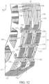
FIG. 12 is a sectional view ofFIG. 11 along an E-E direction; and -
FIG. 13 is a schematic diagram of a lamination inFIG. 11 . - In the accompanying drawings:
1 - stator; 10 - through hole; 101 - teeth; 11 - iron core; 111 - outer surface of the iron core; 112 - fixing hole; 113 - mounting hole; 12 - lamination unit; 121 - lamination; 122 - hole portion; 122a - first hole; 122b - second hole; 122c - third hole; 122d - fourth hole; 123 - first lamination; 124 - second lamination; 125 - third lamination; 126 - fourth lamination; 13 - cavity channel; 13a - inlet; 13b - outlet; 130 - channel group; 131 - first channel group; 132 - second channel group; 133 - first cavity channel; 134 - second cavity channel; 135 - third cavity channel; 136 - fourth cavity channel; 137 - first channel; 138 - second channel; x - axial direction of the stator; r - circumferential direction of the stator; and z - height direction of the stator. - To make the foregoing objectives, features, and advantages of the present invention clearer and easier to understand, specific embodiments of the present invention are described in detail below with reference to the accompanying drawings.
-
FIG. 1 is a schematic diagram of a stator 1 for a motor according to a first embodiment of the present invention.FIG. 2 is a sectional view ofFIG. 1 along an A-A direction. To show a specific structure of acavity channel 13 inside the stator 1 more clearly,FIG. 2 exemplarily illustrates a region of a cross section. - Specifically, a motor (not shown) may include a stator 1 and a casing (which is not shown and may also be referred to as a base), where the casing is adapted to fix and protect the stator 1. For example, the casing may include end caps arranged on two sides of the stator 1 in an axial direction of the stator 1. Further, a wire package (which is not shown and may also be referred to as a coil) may be wound on the stator 1 to form a stator winding.
- For ease of description, in this embodiment, an axial direction of the stator 1 is denoted as an x-direction, a circumferential direction is denoted as an r-direction, and a height direction is denoted as a z-direction. In this embodiment, the height direction of the stator 1 may be parallel to a gravity direction when the stator 1 is stably placed. The stable placement may specifically refer to a placement status when the motor is in operation. In this embodiment, the axial direction (for example, the x-direction) and the circumferential direction (for example, the r-direction) of the stator 1 may be respectively parallel to an axial direction and a circumferential direction of a through
hole 10 formed in the stator 1 and configured to accommodate a rotor. - For example, a plurality of
teeth 101 are arranged around the throughhole 10 at intervals, where eachtooth 101 may be wound with a coil to form the stator. - Specifically, still referring to
FIG. 1 , the stator 1 for a motor in this embodiment includes aniron core 11, which is also referred to as an iron core of the stator or a stator core. For example, theiron core 11 is provided with a throughhole 10, and the plurality ofteeth 101 are arranged around the throughhole 10. In some embodiments, theiron core 11 may be obtained by stacking a plurality oflaminations 121 in the x-direction. - Further, with reference to
FIG. 1 to FIG. 4 , theiron core 11 includes at least onelamination unit 12 arranged in the axial direction of the stator 1 (for example, the x-direction). Referring toFIG. 3 , for eachlamination unit 12, thelamination unit 12 includes a plurality oflaminations 121 arranged in the x-direction. Thelamination unit 12 may be understood as a minimum repeating unit of theiron core 11. Asingle lamination unit 12 may form theiron core 11, or a plurality oflamination units 12 may be sequentially arranged in the x-direction to form theiron core 11.Adjacent lamination units 12 may be closely attached. In some embodiments, thelamination 121 may be, for example, a silicon steel sheet. - Further, still referring to
FIG. 1 andFIG. 2 , the stator 1 further includes at least onecavity channel 13, formed inside thelamination unit 12, where aninlet 13a and anoutlet 13b that are in communication with eachcavity channel 13 are respectively provided on outer surfaces of thelamination unit 12. In other words, for eachcavity channel 13, aninlet 13a and anoutlet 13b that are in communication with thecavity channel 13 are respectively provided on the outer surfaces of thelamination unit 12, to ensure that air can enter thecavity channel 13 through theinlet 13a, and flow to theoutlet 13b along thecavity channel 13 and finally flow out of theiron core 11.FIG. 1 exemplarily shows a flow path of gas in acavity channel 13 by using a curve with a solid arrow. - In this embodiment, the
inlet 13a and theoutlet 13b are determined according to a placement posture of the stator 1. Specifically, based on a current placement posture of the stator 1, when the motor is in operation, a gas inlet is theinlet 13a, and a gas outlet is theoutlet 13b. If a placement direction of the stator 1 changes, positions of theinlet 13a and theoutlet 13b in a vertical direction change. For example, after the stator 1 shown inFIG. 1 rotates clockwise by 90 degrees about an axis extending in the x-direction, theoutlet 13b originally marked in the figure is located below theinlet 13a. Further, in this case, theoriginal outlet 13b may become theinlet 13a, and theoriginal inlet 13a may become theoutlet 13b. - Further, an outer surface of the at least one
lamination unit 12 may jointly form anouter surface 111 of theiron core 11. - Further, the
outlet 13b and theinlet 13a have a height difference in the axial direction of the stator 1 (for example, the x-direction). For example, openings in communication with the outside of theiron core 11 are provided at two ends of thecavity channel 13 in an extension direction. When the stator 1 is stably placed, a lower opening in the z-direction is theinlet 13a, and an upper opening is theoutlet 13b. - Further, an extension path of the
cavity channel 13 from theinlet 13a to theoutlet 13b may extend in the x-direction and in the z-direction in a meandering manner. For example, still referring toFIG. 1 ,cavity channels 13 distributed in different regions of the stator 1 in the r-direction are respectively denoted as afirst cavity channel 133, asecond cavity channel 134, athird cavity channel 135, and afourth cavity channel 136. Flow paths of gas along thecavity channels 13 are respectively shown in the figure (marked by reference numerals of corresponding cavity channels in the figure). - In this way, heat dissipation performance of the stator 1 can be improved, thereby reducing a temperature of the motor and improving efficiency and a power density of the motor.
- Specifically, a
cavity channel 13 of a three-dimensional spatial structure is formed inside theiron core 11 of the stator 1, to increase a heat-dissipation surface area of thelamination 121. Further, there is a height difference between theinlet 13a and theoutlet 13b of thecavity channel 13 in the axial direction of the stator 1, so that air convection is formed. When an airflow flows along thecavity channel 13, the airflow takes away heat generated in theiron core 11. In this way, heat can be directly dissipated from a heat source to the air, thereby further improving heat dissipation efficiency. The stator 1 with better heat dissipation performance can reduce the overall temperature of the motor, and improve the efficiency and a power density, for example, a maximum output capability of the motor. - Further, natural convection is achieved in the
cavity channel 13 by using a self-pulling force of the hot air during rise. An airflow naturally flows in thecavity channel 13 without additionally arranging a driving mechanism to perform air evacuation, thereby improving the heat dissipation efficiency. - When the motor is in operation and the stator 1 generates heat, heat on the stator winding is transferred to the
iron core 11, air in thecavity channel 13 is heated and then takes away heat while flowing along thecavity channel 13 from bottom to top, and cold air is automatically added from the bottom. Compared to a heat-dissipation surface area of a conventional iron core of a stator, a surface area of an interior of each of the plurality ofcavity channels 13 is greatly increased, thereby greatly improving the heat dissipation efficiency. Therefore, the stator 1 in this embodiment can greatly reduce the temperature of the motor, thereby reducing energy consumption of the motor, improving efficiency, and increasing power density of the motor, so that the motor with the same size has higher output. - In some embodiments, the
inlet 13a and theoutlet 13b may be formed on outer surfaces of thelamination unit 12 that are not covered by the casing. - In some embodiments, the plurality of
cavity channels 13 may be independent, where eachcavity channel 13 is provided with arespective inlet 13a andoutlet 13b on outer surfaces of thelamination unit 12. - In a specific implementation, still referring to
FIG. 1 andFIG. 2 , aninlet 13a and anoutlet 13b that are in communication with thesame cavity channel 13 may be respectively arranged on outer surfaces on different sides of thelamination unit 12. - Specifically, for the
same cavity channel 13, aninlet 13a and anoutlet 13b of thecavity channel 13 may be respectively provided on outer surfaces on adjacent sides of thelamination unit 12. Correspondingly, the extension path of thecavity channel 13 inside theiron core 11 extends from one side of theiron core 11 to the other adjacent side. - For example, from the perspective shown in
FIG. 1 andFIG. 2 , a plurality ofcavity channels 13 are arranged in theiron core 11. Some cavity channels 13 (for example, a plurality ofcavity channels 13 in a first channel group 131, as shown inFIG. 6 ) are arranged in the x-direction, where aninlet 13a of eachcavity channel 13 is located on a lower side of theiron core 11, and anoutlet 13b is located on a right side of theiron core 11 from the perspective shown in the figure. Some other cavity channels 13 (for example, a plurality ofcavity channels 13 in a second channel group 132, as shown inFIG. 6 ) are arranged in the x-direction and are completely located above the first channel group 131, where aninlet 13a of eachcavity channel 13 is located on a right side of theiron core 11 from the perspective shown in the figure, and anoutlet 13b is located on an upper side of theiron core 11. - Therefore, a length of the
cavity channel 13 meandered inside theiron core 11 may be increased, to increase the heat dissipation surface area, thereby further facilitating heat dissipation. - In some embodiments, when it is ensured that there is a height difference in the x-direction, an
inlet 13a and anoutlet 13b of thesame cavity channel 13 are respectively provided on two opposite sides of thelamination unit 12. - In some embodiments, the
inlet 13a and theoutlet 13b of thesame cavity channel 13 may not be on the same plane, where the plane is perpendicular to the x-direction. Therefore, thecavity channel 13 extends at least a distance inside theiron core 11 in the x-direction, to ensure that heat inside theiron core 11 is quickly dissipated through thecavity channel 13. - Specifically, the
inlet 13a and theoutlet 13b may be provided ondifferent laminations 121 of thelamination unit 12, so that thecavity channel 13 extends in the x-direction. - In a specific implementation, still referring to
FIG. 1 to FIG. 4 , thelamination unit 12 may include a plurality oflaminations 121, where ahole portion 122 may be formed in eachlamination 121, and thehole portion 122 is suitable for forming a part of thecavity channel 13. - Specifically, the
hole portion 122 may run through thelamination 121 in the x-direction. Correspondingly, a wall of thelamination 121 that forms thehole portion 122 is a part of thecavity channel 13. - Further, a
hole portion 122 formed in the at least onelamination 121 may extend to an edge of thelamination 121, to form aninlet 13a or anoutlet 13b. In this case, thehole portion 122 may also be understood as a notch. - Therefore, the
cavity channel 13 may be formed in theiron core 11 by using a simple lamination process. A production process is simple and easy to implement, and manufacturing costs are low. Further, openings are provided at appropriate positions on eachlamination 121 to form thehole portion 122, and after the plurality oflaminations 121 are finally stacked, a channel of a spatial structure may be formed in theiron core 11 of the stator 1 to facilitate heat dissipation. - In some embodiments, still referring to
FIG. 2 , a larger thickness of thelamination 121 in the x-direction indicates a larger cross-sectional area of the part of thecavity channel 13 formed by the openings on thelamination 121. - In some embodiments, a larger aperture of the
hole portion 122 indicates a larger cross-sectional area of the part of thecavity channel 13 formed by thehole portion 122. - In some embodiments, shapes and structures of the
laminations 121 may be the same or different, so that the design of thecavity channel 13 in this embodiment can be flexibly adapted to theiron core 11 of the stator 1 of various structural designs. - For example, four
laminations 121 of different designs may be stacked in the x-direction to form onelamination unit 12. A notch (that is, ahole portion 122 extending to an edge of the first lamination 121) is sequentially provided below a surface of thefirst lamination 121 in the x-direction, ahole portion 122 is provided on thesecond lamination 121 and the notch on thefirst lamination 121 is in communication with an opening on thesecond lamination 121 in the x-direction, ahole portion 122 is provided on thethird lamination 121 and a front end of an opening is in communication with a tail end of the opening on thesecond lamination 121 in the x-direction, and a notch extending to a side surface is provided on thefourth lamination 121 and an end of the notch is in communication with a tail end of the opening on thethird lamination 121. In this way, every fourlaminations 121 may form a through channel (that is, a cavity channel 13) of a spatial structure,inlets 13a of thecavity channel 13 are formed on a front surface and a lower side of thelamination unit 12 through the notch of thefirst lamination 121, andoutlets 13b of thecavity channel 13 are formed on side surfaces of thelamination unit 12 through the notch of thefourth lamination 121. - In a specific implementation, still referring to
FIG. 1 to FIG. 4 , thelamination unit 12 may include a plurality oflaminations 121 in the same shape, where the plurality oflaminations 121 sequentially rotate by a preset angle to stack into thelamination unit 12, a plurality ofhole portions 122 arranged in a circumferential direction of the stator 1 (for example, the r-direction) may be formed in eachlamination 121, and a plurality ofhole portions 122 respectively formed in every twoadjacent laminations 121 are penetrated in the axial direction of the stator 1 (for example, the x-direction), to form a plurality ofcavity channels 13. - Specifically, a specific value of the preset angle may be determined based on an included angle (or a spacing) between
adjacent hole portions 122 on asingle lamination 121. - For example, in the figure, a square-shaped
lamination 121 is used as an example for exemplary illustration.Hole portions 122 are symmetrically arranged at four corners of the square-shapedlamination 121, and correspondingly, the preset angle may be 90 degrees. In other words, a plurality oflaminations 121 of the same design are stacked one by one and rotate clockwise/counterclockwise by 90 degrees, to finally obtain thelamination unit 12 through one-by-one stacking.FIG. 3 exemplarily shows an example in which alamination unit 12 is obtained by rotating a lamination clockwise by 90 degrees each time the lamination is stacked. - In another example, an outer profile of the
lamination 121 may be circular, and the plurality ofhole portions 122 may be arranged around the throughhole 10 at equal intervals in the r-direction. In this case, the preset angle may be less than a deflection angle of theadjacent hole portions 122 relative to an axis of the throughhole 10. Therefore, the plurality oflaminations 121 with the same opening layout are rotated and stacked, so that theiron core 11 of the stator 1 with the plurality ofcavity channels 13 is manufactured, and the manufacturing process is simple and costs are low. Specifically, a channel of a spatial structure is formed on theiron core 11 of the stator 1 after the plurality oflaminations 121 of the same design are rotated by an angle, to facilitate heat dissipation. Because opening layouts of the openings onlaminations 121 are the same, theentire iron core 11 can be produced by developing a single mold. This reduces opening costs and process complexity. - In some embodiments, all the
hole portions 122 formed on thesingle lamination 121 are at equal distances from the axis of the throughhole 10. In other words, a pattern enclosed by allhole portions 122 on thelamination 121 is a circle, and may be a concentric circle with the throughhole 10. - In some embodiments, a pattern enclosed by all the
hole portions 122 formed on thesingle lamination 121 may be a plurality of concentric circles with the throughhole 10. For example, based on the fact that onehole portion 122 is provided at each of the four corners of the square-shapedlamination 121 shown inFIG. 1 , ahole portion 122 may be additionally arranged on an outer side of eachhole portion 122 in a radial direction of the throughhole 10. In this way, layouts of the plurality ofhole portions 122 on thelamination 121 and the throughhole 10 jointly form three concentric circles. - In this embodiment, the
iron core 11 may be obtained by stacking n types oflaminations 121 as one cycle, where n is an integer greater than or equal to 2. A single cycle is a minimum repeating unit, that is, the single cycle corresponds to asingle lamination unit 12. For example, variant embodiments shown inFIG. 5 to FIG. 7 are exemplarily illustrated by using n=2 as an example, and variant embodiments shown inFIG. 8 to FIG. 10 are exemplarily illustrated by using n=3 as an example. - Further, a number of pieces of each type of
lamination 121 in thesingle lamination unit 12 may be one, as shown inFIG. 1 to FIG. 4 . Alternatively, a number of pieces of each type oflamination 121 in thesingle lamination unit 12 may be more, as shown inFIG. 5 to FIG. 10 . In a variant embodiment, a number of pieces of at least one type oflamination 121 in thesingle lamination unit 12 may be different from a number of pieces of another type oflamination 121. - Further, for n types of
laminations 121 in eachlamination unit 12, a difference between different types oflaminations 121 may be specifically lies in that there is a difference in positions/layouts of openings (for example,hole portions 122 of different types oflaminations 121 in the x-direction are not completely in communication). The difference in the positions/layouts of the openings may be implemented throughlaminations 121 of different structural designs, or may be implemented by rotatinglaminations 121 of the same structural design by a preset angle. - In a specific implementation, still referring to
FIG. 2 andFIG. 3 , thelamination unit 12 may include afirst lamination 123, asecond lamination 124, athird lamination 125, and afourth lamination 126 that are sequentially arranged in the axial direction of the stator 1 (for example, the x-direction). Specifically, twoadjacent laminations 121 may be in surface-to-surface contact. - Further, referring to
FIG. 4 , eachlamination 121 is provided with afirst hole 122a, asecond hole 122b, athird hole 122c, and afourth hole 122d that are sequentially arranged in the circumferential direction of the stator 1 (for example, the r-direction). For example, thefirst hole 122a, thesecond hole 122b, thethird hole 122c, and thefourth hole 122d are arranged at equal intervals around the axis of the throughhole 10. The arrangement at equal intervals may be, for example, that thehole portions 122 are arranged at intervals of 90 degrees. - Further, the
first hole 122a and thefourth hole 122d may each extend to an edge of the same side of thelamination 121. - Further, with reference to
FIG. 1 , the at least onecavity channel 13 may include afirst cavity channel 133, asecond cavity channel 134, athird cavity channel 135, and afourth cavity channel 136. For example, fourcavity channels 13 are distributed around the throughhole 10 in the r-direction, and extend through thelamination unit 12 in the x-direction. - In a variant embodiment in which n=2 shown in
FIG. 6 , thefirst lamination 123, thesecond lamination 124, thethird lamination 125, and thefourth lamination 126 may each include twolaminations 121. In a variant embodiment in which n=3 shown inFIG. 9 , thefirst lamination 123, thesecond lamination 124, thethird lamination 125, and thefourth lamination 126 may each include threelaminations 121. - In some embodiments, every two of the
first hole 122a of thefirst lamination 123, thesecond hole 122b of thesecond lamination 124, thethird hole 122c of thethird lamination 125, and thefourth hole 122d of thefourth lamination 126 are penetrated in the axial direction of the stator 1 (for example, the x-direction), to form thefirst cavity channel 133. From a perspective shown in the figure, thefirst cavity channel 133 is located at a lower right corner of thelamination unit 12, where aninlet 13a is provided at a lower side and a front surface of thelamination unit 12, and anoutlet 13b is provided at a right side surface of thelamination unit 12. Further, theinlet 13a on a lower side and theoutlet 13b on an upper side of thefirst cavity channel 133 are located ondifferent laminations 121. For example, theinlet 13a and theoutlet 13b are respectively located on thefirst lamination 123 and thefourth lamination 126. - Similarly, every two of the
second hole 122b of thefirst lamination 123, thethird hole 122c of thesecond lamination 124, and thefourth hole 122d of thethird lamination 125 are penetrated in the axial direction of the stator 1 (for example, the x-direction), to form thesecond cavity channel 134. From a perspective shown in the figure, thesecond cavity channel 134 may be located at an upper right corner of thelamination unit 12, where aninlet 13a of thesecond cavity channel 134 is provided on a front surface of the lamination unit 12 (where thesecond hole 122b of thefirst lamination 123 is reused) and is located above theoutlet 13b of thefirst cavity channel 133, and anoutlet 13b of thesecond cavity channel 134 may be provided above the lamination unit 12 (where thefourth hole 122d of thethird lamination 125 is reused). - Similarly, each of the
third hole 122c of thefirst lamination 123 and thefourth hole 122d of thesecond lamination 124, and thefirst hole 122a of thethird lamination 125 and thesecond hole 122b of thefourth lamination 126 may be in communication in the axial direction of the stator 1 (for example, the x-direction), to form twothird cavity channels 135. From a perspective shown in the figure, the twothird cavity channels 135 are each located at an upper left corner of thelamination unit 12 and arranged from front to back in the x-direction. Aninlet 13a of the frontthird cavity channel 135 is provided on a left side surface of the lamination unit 12 (where thefourth hole 122d of thesecond lamination 124 is reused) and is located above anoutlet 13b of thefourth cavity channel 136 that is also provided on the left side surface. Anoutlet 13b of the frontthird cavity channel 135 may be provided on a front surface of the lamination unit 12 (where thethird hole 122c of thefirst lamination 123 is reused). Aninlet 13a of the rearthird cavity channel 135 is provided on a rear surface of the lamination unit 12 (where thesecond hole 122b of thefourth lamination 126 is reused) and is located above anoutlet 13b of thefourth cavity channel 136. Anoutlet 13b of the rearthird cavity channel 135 may be provided above the lamination unit 12 (where thefirst hole 122a of thethird lamination 125 is reused). - Similarly, every two of the
first hole 122a of thesecond lamination 124, thesecond hole 122b of thethird lamination 125, and thethird hole 122c of thefourth lamination 126 are penetrated in the axial direction of the stator 1 (for example, the x-direction), to form thefourth cavity channel 136. From a perspective shown in the figure, thefourth cavity channel 136 may be located at a lower left corner of thelamination unit 12, where aninlet 13a is provided on the rear surface of the lamination unit 12 (where thethird hole 122c of thefourth lamination 126 is reused), and anoutlet 13b is formed on the left side surface of the lamination unit 12 (where thefirst hole 122a of thesecond lamination 124 is reused). - Therefore, the
single lamination unit 12 has fourcavity channels 13 distributed in the circumferential direction of the stator 1, and eachcavity channel 13 penetrates through at least a part of the interior of thelamination unit 12 in the axial direction of the stator 1, so that heat inside theiron core 11 can naturally flow from theinlet 13a on the lower side to theoutlet 13b on the upper side/side surface along thecavity channel 13, and the heat is quickly dissipated to the outside of theiron core 11. - Further, the
iron core 11 obtained by arranging the plurality oflamination units 12 in the x-direction is provided withinlets 13a andoutlets 13b of thecavity channel 13 on four sides (for example, upper and lower and left and right sides from the perspective shown in the figure) in the circumferential direction (for example, the r-direction). In this way, an airflow can flow more omnidirectionally inside theiron core 11 to quickly take away heat inside theiron core 11. In addition, when theiron core 11 is placed in any posture, aninlet 13a and anoutlet 13b that are adapted to be provided on side surfaces form acavity channel 13 in communication with the outside, to achieve heat dissipation. - In some embodiments,
adjacent lamination units 12 may jointly form thecavity channel 13. This helps increase a length of thecavity channel 13 extending in theiron core 11, and further improve heat dissipation performance. - For example, still referring to
FIG. 3 , for twoadjacent lamination units 12 in the x-direction, thefirst hole 122a of thefourth lamination 126 in thefront lamination unit 12 may form thesecond cavity channel 134 together with thesecond hole 122b of thefirst lamination 123, thethird hole 122c of thesecond lamination 124, and thefourth hole 122d of thethird lamination 125 in therear lamination unit 12. Therefore, a longersecond cavity channel 134 facilitates better heat dissipation. - Further, in this example, the
inlet 13a of thesecond cavity channel 134 may reuse thefirst hole 122a of thefourth lamination 126 in thefront lamination unit 12. In other words, theinlet 13a of thesecond cavity channel 134 may be provided on a right side of theiron core 11 from the perspective shown in the figure, and is located above theoutlet 13b of thefirst cavity channel 133 that is also provided on the right side. Therefore, gas flowing out offirst cavity channels 133 of the twoadjacent lamination units 12 may enter theiron core 11 again through theinlet 13a of thesecond cavity channel 134. This helps increase a path through which the airflow flows in theiron core 11, thereby improving heat dissipation efficiency. - In another example, for the two
adjacent lamination units 12 in the x-direction, thefourth hole 122d of thesecond lamination 124 and thethird hole 122c of thefirst lamination 123 in therear lamination unit 12 may form thethird cavity channel 135 together with thesecond hole 122b of thefourth lamination 126 and thefirst hole 122a of thethird lamination 125 in thefront lamination unit 12. Therefore, compared with thethird cavity channel 135 formed by thehole portions 122 on the twolaminations 121 in the foregoing embodiment, thethird cavity channel 135 jointly formed by the fourlaminations 121 in this example is longer, and more heat inside theiron core 11 can be taken away. - Further, in this example, the
inlet 13a of thethird cavity channel 135 may reuse thefourth hole 122d of thesecond lamination 124 in therear lamination unit 12, and theoutlet 13b may reuse thefirst hole 122a of thethird lamination 125 in thefront lamination unit 12. In other words, theinlet 13a of thethird cavity channel 135 is provided on a left side of theiron core 11 from the perspective shown in the figure and is located above theoutlet 13b of thefourth cavity channel 136 that is also provided on the left side, and theoutlet 13b of thethird cavity channel 135 is provided on the top of theiron core 11 from the perspective shown in the figure. Therefore, gas flowing out offourth cavity channels 136 of the twoadjacent lamination units 12 may enter theiron core 11 again through theinlet 13a of thethird cavity channel 135. This helps increase a path through which the airflow flows in theiron core 11, thereby improving the heat dissipation efficiency. - In another example, for two
adjacent lamination units 12 in the x-direction, thefourth hole 122d of thefirst lamination 123 in therear lamination unit 12 may form thefourth cavity channel 136 together with thefirst hole 122a of thesecond lamination 124, thesecond hole 122b of thethird lamination 125, and thethird hole 122c of thefourth lamination 126 in thefront lamination unit 12. Therefore, a longerfourth cavity channel 136 facilitates better heat dissipation. - Further, in this example, the
inlet 13a of thefourth cavity channel 136 may reuse thefourth hole 122d of thefirst lamination 123 in therear lamination unit 12, and theoutlet 13b may reuse thefirst hole 122a of thesecond lamination 124 in thefront lamination unit 12. In other words, theinlet 13a of thefourth cavity channel 136 is provided on the bottom of theiron core 11 from the perspective shown in the figure, and theoutlet 13b is provided on the left side of theiron core 11 from the perspective shown in the figure. - In a variant embodiment, sizes and positions of a
first hole 122a, asecond hole 122b, athird hole 122c, and afourth hole 122d on eachlamination 121 are adjusted, so that every two of asecond hole 122b of afirst lamination 123, athird hole 122c of asecond lamination 124, afourth hole 122d of thethird lamination 125, and afirst hole 122a of afourth lamination 126 on thesame lamination unit 12 may be in communication in the axial direction of the stator 1 (for example, the x-direction), to form thesecond cavity channel 134. Therefore, thesecond cavity channel 134 formed in thesingle lamination unit 12 fully useshole portions 122 of alllaminations 121, to maximize the length of thecavity channel 13, and increase the heat dissipation surface area inside theiron core 11. - Similarly, sizes and positions of the
first hole 122a, thesecond hole 122b, thethird hole 122c, and thefourth hole 122d on thelamination 121 are adjusted, so that twothird cavity channels 135 may be penetrated into one cavity channel from front to back. Theinlet 13a may reuse thethird hole 122c of thefirst lamination 123, and theoutlet 13b may reuse thesecond hole 122b of thefourth lamination 126. - In some embodiments, the casing may avoid a
hole portion 122 on a front surface of thelamination 121, to block theinlet 13a and/or theoutlet 13b of thecavity channel 13. For example, when theinlet 13a of thesecond cavity channel 134 is provided on the front surface of thelamination unit 12, the casing that covers two sides of thelamination unit 12 in the x-direction may avoid thesecond hole 122b of thefirst lamination 123, to ensure that thesecond cavity channel 134 is reliably in communication with the outside. - In a specific implementation, still referring to
FIG. 1 to FIG. 10 , for eachcavity channel 13, projections of thehole portions 122 formed in theadjacent laminations 121 and suitable for forming thecavity channel 13 at least partially overlap in the axial direction of the stator 1 (for example, the x-direction). - Specifically, openings and/or notches on two
adjacent laminations 121 in the x-direction at least partially overlap. - The
first cavity channel 133 is used as an example. Refer toFIG. 2 ,FIG. 6 , andFIG. 9 . Projections of thefirst hole 122a of thefirst lamination 123 and thesecond hole 122b of thesecond lamination 124 in the x-direction overlap end to end, projections of thesecond hole 122b of thesecond lamination 124 and thethird hole 122c of thethird lamination 125 in the x-direction overlap end to end, and projections of thethird hole 122c of thethird lamination 125 and thefourth hole 122d of thefourth lamination 126 in the x-direction overlap end to end. The end-to-end overlapping specifically means that, in a flow direction of an airflow in thecavity channel 13, a tail end of afront hole portion 122 and a front end of arear hole portion 122 are penetrated from front to back in the x-direction. - Therefore, it is ensured that after the plurality of
laminations 121 are stacked, the front andrear hole portions 122 remain in communication, to form a through channel inside theiron core 11 of the stacked stator 1. - In a specific implementation, referring to
FIG. 6 andFIG. 9 , projections ofhole portions 122 provided on at least twoadjacent laminations 121 in the axial direction of the stator 1 (for example, the x-direction) may completely overlap. - In other words, a plurality of
laminations 121 in at least onelamination unit 12 in the stator 1 may be obtained by stacking every n types oflaminations 121 as one cycle. A number of pieces of each type oflamination 121 is more (that is, two or more), where n is an integer greater than or equal to 2. - For example, in variant embodiments shown in
FIG. 5 to FIG. 7 , asingle lamination unit 12 may include twofirst laminations 123, twosecond laminations 124, twothird laminations 125, and twofourth laminations 126. The twofirst laminations 123, the twosecond laminations 124, the twothird laminations 125, and the twofourth laminations 126 are sequentially stacked in the x-direction. - In another example, in variant embodiments shown in
FIG. 8 to FIG. 10 , asingle lamination unit 12 may include threefirst laminations 123, threesecond laminations 124, threethird laminations 125, and threefourth laminations 126. The threefirst laminations 123, the threesecond laminations 124, the threethird laminations 125, and the threefourth laminations 126 are sequentially stacked in the x-direction. - In this way, the surface area of the interior of the
cavity channel 13 is larger. This increases a flow speed of an airflow in thecavity channel 13, and further improves the heat dissipation efficiency. Specifically, considering that asingle lamination 121 is thin, positions of the openings on a plurality ofadjacent laminations 121 are kept consistent, a cross-sectional area of a segment of thecavity channel 13 is increased. Because the flow speed of the airflow in thecavity channel 13 is slow due to a viscosity effect near a wall of thecavity channel 13, the increased cross-sectional area is beneficial for increasing the flow speed of the airflow in the segment of thecavity channel 13. - In a specific implementation, in the axial direction of the stator 1 (for example, the x-direction), projections of the
hole portions 122 that are formed in eachlamination 121 included in thelamination unit 12 and that are suitable for forming thesame cavity channel 13 may deflect clockwise or anticlockwise in the axial direction of the stator 1. - The
first cavity channel 133 is used as an example. Still refer toFIG. 3 ,FIG. 7 , andFIG. 10 . Fourhole portions 122, namely, thefirst hole 122a of thefirst lamination 123, thesecond hole 122b of thesecond lamination 124, thethird hole 122c of thethird lamination 125, and thefourth hole 122d of thefourth lamination 126 sequentially deflect counterclockwise from a lower edge to a right edge of thelamination unit 12 from the perspective shown in the figure. Correspondingly, thefirst cavity channel 133 arranged at the lower right corner of thelamination unit 12 extends in the x-direction from a position near the lower side toward the interior of thelamination unit 12, and extends counterclockwise from the perspective shown in the figure. - Therefore, the
cavity channel 13 rotationally extends in the circumferential direction of the stator 1 (for example, the r-direction) while extending toward the interior of theiron core 11 in the axial direction of the stator 1 (for example, the x-direction). This helps increase the length of thecavity channel 13 extending inside theiron core 11 in a meandering manner, to optimize a heat dissipation effect, and improve balance of heat dissipation at various positions of theiron core 11. - In a specific implementation, still referring to
FIG. 2 ,FIG. 6 , andFIG. 9 , forlamination units 12 other than first andlast lamination units 12 among the plurality oflamination units 12,hole portions 122 formed in the first andlast laminations 121 in thelamination unit 12 may be in communication with edges ofrespective laminations 121 where the hole portions are located. - In other words, for a
lamination unit 12 that is of the plurality oflamination units 12 and sandwiched by the front/rear lamination unit 12,hole portions 122 arranged on first andlast laminations 121 of thelamination unit 12 extends in an extension direction to an edge of thelamination 121 to form a notch. Correspondingly, for acavity channel 13 formed on a sandwichedlamination unit 12, aninlet 13a and anoutlet 13b of thecavity channel 13 are provided on side surfaces of thelamination unit 12 around the r-direction. - In this way, it is ensured that the
inlet 13a and theoutlet 13b of thecavity channel 13 of thelamination unit 12 located in the middle are reliably in communication with the outside of theiron core 11, to provide a channel for gas convection. - In some embodiments, openings on first and
last laminations 121 of first andlast lamination units 12 of the plurality oflamination units 12 may also extend in the extension direction to be in communication with an edge of thelamination 121. Therefore, when the casing covers an outer surface of thefirst lamination 121 of thefirst lamination unit 12 and an outer surface of thelast lamination 121 of thelast lamination unit 12 arranged in the x-direction, acavity channel 13 on the first andlast lamination units 12 can still ensure reliable communication with the outside of theiron core 11. - In a specific implementation, a number of the plurality of
laminations 121 included in thelamination unit 12 may be related to a size ofhole portions 122 formed in eachlamination 121 and an overlapping area ofhole portions 122 formed inadjacent laminations 121 in the axial direction of the stator 1 (for example, the x-direction). - For example, if a
hole portion 122 formed on asingle lamination 121 has a larger size in the extension direction, acavity channel 13 penetrating through thelamination unit 12 may be obtained by stacking a smaller number of different types oflaminations 121. Correspondingly, asingle lamination unit 12 includesfewer laminations 121. - In another example, if an overlapping area between
hole portions 122 arranged onadjacent laminations 121 in the x-direction is larger, a larger number oflaminations 121 need to be rotated and stacked to obtain acavity channel 13 that penetrates through thelamination unit 12 and forms openings on at least two sides of the lamination unit. Correspondingly, asingle lamination unit 12 includesmore laminations 121. - Therefore, a number of
laminations 121 included in a minimum repeating unit is properly designed according to a size of an opening on eachlamination 121 and an overlapping degree of openings onadjacent laminations 121. This helps arrange asmany cavity channels 13 as possible by using a space on theiron core 11 to a maximum extent, to obtain a better heat dissipation effect. - In a specific implementation, still referring to
FIG. 2 ,FIG. 6 , andFIG. 9 , at least onecavity channel 13 may include at least onechannel group 130 arranged in the circumferential direction of the stator 1 (for example, the r-direction). Eachchannel group 130 may include at least onefirst channel 137 arranged in the axial direction of the stator 1 (for example, the x-direction). - Specifically,
cavity channels 13 arranged in different regions of theiron core 11 in the r-direction may be divided intodifferent channel groups 130. - Further,
inlets 13a offirst channels 137 in thesame channel group 130 may be located on the same side of theiron core 11. Similarly,outlets 13b of thefirst channels 137 in thesame channel group 130 may also be located on the same side of theiron core 11. - Further,
inlets 13a offirst channels 137 indifferent channel groups 130 may be located on different sides of theiron core 11. Similarly,outlets 13b of thefirst channels 137 in thedifferent channel groups 130 may also be located on different sides of theiron core 11. - For example, when n=1, four
hole portions 122 are arranged at intervals on eachlamination 121 around the r-direction, and the stator 1 includes fourlamination units 12, referring toFIG. 1 andFIG. 2 , theiron core 11 may include fourchannel groups 130 respectively located at four corners of arectangular lamination 121, and eachchannel group 130 includes fourfirst channels 137.FIG. 1 shows an example in which fourlamination units 12 are stacked in an x-direction, andFIG. 2 shows an internal structure by using three of thelamination units 12 as an example. - Specifically, four
first cavity channels 133 belong to thesame channel group 130, foursecond cavity channels 134 belong to thesame channel group 130, fourthird cavity channels 135 belong to thesame channel group 130, and fourfourth cavity channels 136 belong to thesame channel group 130. Each of thefirst cavity channel 133, thesecond cavity channel 134, thethird cavity channel 135, and thefourth cavity channel 136 may be considered as afirst channel 137. - For example, when n=2, four
hole portions 122 are arranged at intervals on eachlamination 121 around the r-direction, and the stator 1 includes twolamination units 12, referring toFIG. 5 andFIG. 6 , theiron core 11 may include fourchannel groups 130 respectively located at four corners of arectangular lamination 121, and eachchannel group 130 includes twofirst channels 137. - Specifically, two
first cavity channels 133 belong to thesame channel group 130, twosecond cavity channels 134 belong to thesame channel group 130, twothird cavity channels 135 belong to thesame channel group 130, and twofourth cavity channels 136 belong to thesame channel group 130. Each of thefirst cavity channel 133, thesecond cavity channel 134, thethird cavity channel 135, and thefourth cavity channel 136 may be considered as afirst channel 137. - In another example, when n=3, four
hole portions 122 are arranged at intervals on eachlamination 121 around the r-direction, and the stator 1 includes twolamination units 12, referring toFIG. 8 andFIG. 9 , theiron core 11 may include twochannel groups 130 respectively located at four corners of arectangular lamination 121, and eachchannel group 130 includes twofirst channels 137.FIG. 8 shows an example in which twolamination units 12 are stacked in an x-direction, andFIG. 9 shows an internal structure by using one of thelamination units 12 as an example. - Specifically, two
first cavity channels 133 belong to thesame channel group 130, twosecond cavity channels 134 belong to thesame channel group 130, twothird cavity channels 135 belong to thesame channel group 130, and twofourth cavity channels 136 belong to thesame channel group 130. Each of thefirst cavity channel 133, thesecond cavity channel 134, thethird cavity channel 135, and thefourth cavity channel 136 may be considered as afirst channel 137. - Further, the
first channel 137 may be formed by providing openings onlaminations 121 of thesingle lamination unit 12. - The
first cavity channel 133 is used as an example. Fourlaminations 121 of thesingle lamination unit 12 may form onefirst cavity channel 133. - Alternatively, the
first channel 137 may also be jointly formed bylaminations 121 ofadjacent lamination units 12. Thesecond cavity channel 134 is used as an example. Thelaminations 121 of theadjacent lamination units 12 jointly form onesecond cavity channel 134. - Therefore, at least one
channel group 130 is distributed along the circumferential direction of the stator 1 (for example, the r-direction), and afirst channel 137 in eachchannel group 130 penetrates through at least a part of theiron core 11 along the axial direction of the stator 1 (for example, the x-direction), so that heat inside theiron core 11 can naturally flow from alower inlet 13a of eachfirst channel 137 to anupper outlet 13b along thefirst channel 137, thereby quickly dissipating heat to the outside of theiron core 11. - Further, for each
channel group 130, a plurality of independentfirst channels 137 are provided, so that numbers ofinlets 13a andoutlets 13b can be increased, and the heat dissipation surface area inside theiron core 11 may further be increased, to better improve the heat dissipation performance. - In a specific implementation, still referring to
FIG. 1 to FIG. 10 , the at least onechannel group 130 may include a first channel group 131 and a second channel group 132. In the axial direction of the stator 1 (for example, the x-direction), the second channel group 132 and the first channel group 131 may have a height difference. - For example, referring to
FIG. 6 , the first channel group 131 may include at least onefirst cavity channel 133 arranged in the x-direction, and the second channel group 132 may include at least onesecond cavity channel 134 arranged in the x-direction. In the z-direction, the first channel group 131 may be located below the second channel group 132. - In another example, the first channel group 131 may include at least one
fourth cavity channel 136 arranged in the x-direction, and the second channel group 132 may include at least onethird cavity channel 135 arranged in the x-direction. In the z-direction, the first channel group 131 may be located below the second channel group 132. - Further, an
outlet 13b in communication with eachfirst channel 137 in the first channel group 131 and aninlet 13a in communication with eachfirst channel 137 in the second channel group 132 may be located on an outer surface of the same side of thelamination unit 12. - For example, the first channel group 131 includes the
first cavity channel 133, and the second channel group 132 includes thesecond cavity channel 134. Anoutlet 13b of the first channel group 131 is located on a right side of theiron core 11, and aninlet 13a of the second channel group 132 is also located on the right side of the iron core and is located above theoutlet 13b of the first channel group 131. Theoutlet 13b of the first channel group 131 may reuse thefourth hole 122d of thefourth lamination 123, and theinlet 13a of the second channel group 132 may reuse thefirst hole 122a of thefourth lamination 126. - For example, the first channel group 131 includes a
fourth cavity channel 136, and the second channel group 132 includes athird cavity channel 135. Anoutlet 13b of the first channel group 131 is located on a left side of theiron core 11, and aninlet 13a of the second channel group 132 is also located on the left side of the iron core and is located above theoutlet 13b of the first channel group 131. Theoutlet 13b of the first channel group 131 may reuse thefirst hole 122a of thesecond lamination 124, and theinlet 13a of the second channel group 132 may reuse thefourth hole 122b of thesecond lamination 124. - In this way, an airflow enters the second channel group 132 through the first channel group 131 and then is finally discharged out of the motor, to increase the length of the
cavity channel 13 through which the airflow flows inside theiron core 11 as a whole, and bring more heat out of theiron core 11 as much as possible, thereby further enhancing the heat dissipation effect. - In a specific implementation, referring to
FIG. 11 to FIG. 13 , thecavity channel 13 may further include asecond channel 138, and at least some adjacentfirst channels 137 of the plurality offirst channels 137 are in communication with each other through thesecond channel 138. - Specifically, a number of openings on the
laminations 121 is increased. In this way, in addition to thefirst channel 137 extending from bottom to top in a meandering manner, thecavity channel 13 obtained by rotating and stacking the plurality oflaminations 121 may further include asecond channel 138 extending in the axial direction of the stator 1 (for example, the x-direction). - For example,
first channels 137 in eachchannel group 130 are in communication through correspondingsecond channels 138. - Further, the
second channel 138 may be configured to be in communicate with afirst channel 137 of adjacent minimum repeating units (for example, lamination units 12). For example, based on vertical passages originally extending around the circumferential direction of the stator 1, passages linearly extending in the axial direction of the stator 1 are added to be in communication with the vertical passages. In this way, the heat dissipation surface area inside the iron core may be further increased, to optimize the heat dissipation effect. - In some embodiments, a density of
hole portions 122 arranged in the circumferential direction of the stator 1 (for example, the r-direction) may be increased, to increase the number of openings on thelamination 121. For example, referring toFIG. 13 , for eachsquare lamination 121, twohole portions 122 may be formed at each corner of thelamination 121, where one of the twohole portions 122 extends to an edge of thelamination 122 in a direction away from the other hole portion. Further, thehole portions 122 formed at the four corners may be symmetric vertically and horizontally. - In some embodiments, the
hole portion 122 may extend in an arc shape. Further, a radian of the arc may be fitted with a radian of the throughhole 10. - In some embodiments, each
lamination 121 may be provided with fixingholes 112 spaced apart in the circumferential direction r. For eachlamination unit 12, fixingholes 112 on alllaminations 121 included in thelamination unit 12 are penetrated in the x-direction. Further, each fixinghole 112 is adapted to fit with a fixing member such as a screw to fix at least onelamination unit 12 into one body. - In some embodiments, each
lamination 121 may be provided with mountingholes 113 spaced apart in the circumferential direction r, for mounting an insulating skeleton (not shown). During actual application, the mountinghole 113 may be eliminated. - An embodiment of the present invention further provides a motor, including the stator 1 shown in any one of the foregoing embodiments shown in
FIG. 1 to FIG. 13 . The stator 1 with a better heat dissipation effect is used, so that the motor has less a less power consumption loss and a higher power density. - An embodiment of the present invention further provides a household appliance, including: a housing; and a motor, arranged in the housing, where the motor includes the stator 1 according to any one of the foregoing embodiments shown in
FIG. 1 to FIG. 13 . In some embodiments, the household appliance may be, for example, a refrigerating appliance, a washing machine, a drying machine, or a range hood. The refrigerating appliance may include a refrigerator, a freezer, and the like. In this embodiment, a stator 1 with a better heat dissipation effect is used, so that a motor arranged in the household appliance has less a less power consumption loss and a higher power density. This helps reduce overall power consumption of the household appliance, and better meet an energy-saving environmental requirement. - Although specific implementations have been described above, these implementations are not intended to limit the scope of the present disclosure, even if only one implementation is described with respect to specific features. The feature example provided in the present disclosure is intended to be illustrative rather than limiting, unless otherwise stated. In a specific implementation, the technical features of one or more dependent claims may be combined with the technical features of the independent claims, and the technical features from the corresponding independent claims may be combined in any appropriate manner, rather than only in the specific combinations listed in the claims.
- Although the present invention is disclosed above, the present invention is not limited thereto. Any person skilled in the art may make various changes and modifications without departing from the spirit and the scope of the present invention. Therefore, the protection scope of the present invention should be subject to the scope defined by the claims.
Claims (15)
- A stator for a motor, characterized by comprising:an iron core (11), comprising at least one lamination unit (12) arranged in an axial direction of the stator; andat least one cavity channel (13), formed inside the lamination unit (12), wherein an inlet (13a) and an outlet (13b) that are in communication with each cavity channel (13) are respectively formed on outer surfaces of the lamination unit (12), and in the axial direction of the stator, the outlet (13b) and the inlet (13a) have a height difference.
- The stator according to claim 1, characterized in that inlets (13a) and outlets (13b) that are in communication with the same cavity channel (13) are respectively formed on outer surfaces on different sides of the lamination unit (12).
- The stator according to claims 1 or 2, characterized in that the lamination unit (12) comprises a plurality of laminations (121), a hole portion (122) is formed in each lamination (121), and the hole portion (122) is suitable for forming a part of the cavity channel (13).
- The stator according to any of the preceding claims, characterized in that the lamination unit (12) comprises a plurality of laminations (121) in the same shape, wherein the plurality of laminations (121) sequentially rotate by a preset angle to stack into the lamination unit (12), a plurality of hole portions (122) arranged in a circumferential direction of the stator are formed in each lamination (121), and a plurality of hole portions (122) respectively formed in every two adjacent laminations (121) are penetrated in the axial direction of the stator, to form a plurality of cavity channels (13).
- The stator according to any of the preceding claims, characterized in that the lamination unit (12) comprises a first lamination (123), a second lamination (124), a third lamination (125), and a fourth lamination (126) that are sequentially arranged in the axial direction of the stator, a first hole (122a), a second hole (122b), a third hole (122c), and a fourth hole (122d) that are sequentially arranged in the circumferential direction of the stator are formed in the laminations (121), and the at least one cavity channel (13) comprises a first cavity channel (133), a second cavity channel (134), a third cavity channel (135), and a fourth cavity channel (136), wherein every two of the first hole (122a) of the first lamination (123), the second hole (122b) of the second lamination (124), the third hole (122c) of the third lamination (125), and the fourth hole (122d) of the fourth lamination (126) are penetrated in the axial direction of the stator to form the first cavity channel (133), every two of the second hole (122b) of the first lamination (123), the third hole (122c) of the second lamination (124), the fourth hole (122d) of the third lamination (125), and the first hole (122a) of the fourth lamination (126) are penetrated in the axial direction of the stator to form the second cavity channel (134), every two of the third hole (122c) of the first lamination (123), the fourth hole (122d) of the second lamination (124), the first hole (122a) of the third lamination (125), and the second hole (122b) of the fourth lamination (126) are penetrated in the axial direction of the stator to form the third cavity channel (135), and every two of the fourth hole (122d) of the first lamination (123), the first hole (122a) of the second lamination (124), the second hole (122b) of the third lamination (125), and the third hole (122c) of the fourth lamination (126) are in communication in the axial direction of the stator to form the fourth cavity channel (136).
- The stator according to any of the preceding claims, characterized in that for each cavity channel (13), projections of the hole portions (122) formed in the adjacent laminations (121) and suitable for forming the cavity channel (13) at least partially overlap in the axial direction of the stator.
- The stator according to any of the preceding claims , characterized in that the projections of the hole portions (122) formed in at least two adjacent laminations (121) completely overlap in the axial direction of the stator.
- The stator according to any of the preceding claims , characterized in that in the axial direction of the stator, projections of the hole portions (122) that are formed in each lamination (121) comprised in the lamination unit (12) and that are suitable for forming the same cavity channel (13) deflect clockwise or anticlockwise in the axial direction of the stator.
- The stator according to any of the preceding claims , characterized in that for lamination units (12) other than first and last lamination units (12) among the plurality of lamination units (12), hole portions (122) formed in the first and last laminations (121) in the lamination unit (12) are in communication with edges of respective laminations (121) where the hole portions are located.
- The stator according to any of the preceding claims , characterized in that a number of the plurality of laminations (121) comprised in the lamination unit (12) is related to a size of hole portions (122) formed in each lamination (121) and an overlapping area of hole portions (122) formed in adjacent laminations (121) in the axial direction of the stator.
- The stator according to any of the preceding claims , characterized in that the at least one cavity channel (13) comprises at least one channel group (130) arranged in a circumferential direction of the stator, wherein each channel group (130) comprises at least one first channel (137) arranged in the axial direction of the stator.
- The stator according to any of the preceding claims , characterized in that the at least one channel group (130) comprises a first channel group (131) and a second channel group (132), and in the axial direction of the stator, the second channel group (132) and the first channel group (131) have a height difference, wherein the outlet (13b) in communication with each first channel (137) in the first channel group (131) and the inlet (13a) in communication with each first channel (137) in the second channel group (132) are located on an outer surface of the same side of the lamination unit (12).
- The stator according to any of the preceding claims , characterized in that the cavity channel (13) further comprises second channels (138), and at least some adjacent first channels (137) of the plurality of first channels (137) are in communication with each other through the second channels (138).
- A motor, characterized by comprising:
the stator according to any one of claims 1 to 13. - A household appliance, characterized by comprising:a housing; andthe motor according to claim 14, arranged in the housing.
Applications Claiming Priority (1)
| Application Number | Priority Date | Filing Date | Title |
|---|---|---|---|
| CN202311027793.1A CN119496312A (en) | 2023-08-15 | 2023-08-15 | Stators for motors, motors and household appliances |
Publications (1)
| Publication Number | Publication Date |
|---|---|
| EP4510425A1 true EP4510425A1 (en) | 2025-02-19 |
Family
ID=91737689
Family Applications (1)
| Application Number | Title | Priority Date | Filing Date |
|---|---|---|---|
| EP24184937.1A Pending EP4510425A1 (en) | 2023-08-15 | 2024-06-27 | Stator core comprising cooling channels in a motor of a household appliance |
Country Status (3)
| Country | Link |
|---|---|
| US (1) | US20250062647A1 (en) |
| EP (1) | EP4510425A1 (en) |
| CN (1) | CN119496312A (en) |
Citations (4)
| Publication number | Priority date | Publication date | Assignee | Title |
|---|---|---|---|---|
| DE3334501A1 (en) * | 1982-09-25 | 1984-03-29 | Fuji Electric Co., Ltd., Kawasaki, Kanagawa | Method for producing laminated iron cores for electrical machines and apparatuses, and an arrangement of a laminated iron core produced according to said method |
| DE102015215762A1 (en) * | 2015-08-19 | 2017-02-23 | Continental Automotive Gmbh | Laminated core and method for its production |
| US20220239170A1 (en) * | 2019-01-16 | 2022-07-28 | Borgwarner Inc. | Integrated stator cooling jacket system |
| CN115242004A (en) * | 2022-08-05 | 2022-10-25 | 小米汽车科技有限公司 | Stator, motor and vehicle |
Family Cites Families (12)
| Publication number | Priority date | Publication date | Assignee | Title |
|---|---|---|---|---|
| DE102006044963B3 (en) * | 2006-09-22 | 2008-06-19 | Siemens Ag | Stator for an electric machine with liquid cooling |
| US20120080983A1 (en) * | 2010-10-05 | 2012-04-05 | Trevor Iund | Stator with cooling system and associated motor |
| GB2499235A (en) * | 2012-02-10 | 2013-08-14 | Rolls Royce Plc | A cooling arrangement for an electrical machine |
| US9419479B2 (en) * | 2013-03-14 | 2016-08-16 | Baldor Electric Company | Micro-channel heat exchanger for stator of electrical machine with supply header |
| EP3832849A4 (en) * | 2018-07-27 | 2021-08-25 | Mitsubishi Electric Corporation | ELECTRIC MOTOR, COMPRESSOR AND AIR CONDITIONING |
| CN113454878B (en) * | 2019-01-16 | 2025-01-14 | 博格华纳公司 | Integrated stator cooling jacket system |
| US12368332B2 (en) * | 2019-01-16 | 2025-07-22 | Borgwarner Inc. | Integrated stator cooling jacket system |
| US11218050B2 (en) * | 2019-06-06 | 2022-01-04 | GM Global Technology Operations LLC | Motor stator back-iron cooling through internal channels |
| CN114844244A (en) * | 2021-02-01 | 2022-08-02 | 宁波高悦电机技术有限公司 | Motor and motor stator |
| US12126242B2 (en) * | 2022-01-19 | 2024-10-22 | GM Global Technology Operations LLC | Motor stator coolant distribution via internal channels |
| DE102022101923A1 (en) * | 2022-01-27 | 2023-07-27 | Schaeffler Technologies AG & Co. KG | stator |
| CN119742949A (en) * | 2022-05-10 | 2025-04-01 | 小米汽车科技有限公司 | Oil-cooled motor |
-
2023
- 2023-08-15 CN CN202311027793.1A patent/CN119496312A/en active Pending
-
2024
- 2024-06-24 US US18/751,879 patent/US20250062647A1/en active Pending
- 2024-06-27 EP EP24184937.1A patent/EP4510425A1/en active Pending
Patent Citations (4)
| Publication number | Priority date | Publication date | Assignee | Title |
|---|---|---|---|---|
| DE3334501A1 (en) * | 1982-09-25 | 1984-03-29 | Fuji Electric Co., Ltd., Kawasaki, Kanagawa | Method for producing laminated iron cores for electrical machines and apparatuses, and an arrangement of a laminated iron core produced according to said method |
| DE102015215762A1 (en) * | 2015-08-19 | 2017-02-23 | Continental Automotive Gmbh | Laminated core and method for its production |
| US20220239170A1 (en) * | 2019-01-16 | 2022-07-28 | Borgwarner Inc. | Integrated stator cooling jacket system |
| CN115242004A (en) * | 2022-08-05 | 2022-10-25 | 小米汽车科技有限公司 | Stator, motor and vehicle |
Also Published As
| Publication number | Publication date |
|---|---|
| CN119496312A (en) | 2025-02-21 |
| US20250062647A1 (en) | 2025-02-20 |
Similar Documents
| Publication | Publication Date | Title |
|---|---|---|
| JP5080603B2 (en) | Apparatus and method for cooling an electric machine | |
| US11355976B2 (en) | Integral fluid cooling of electrical machine | |
| EP0909004B1 (en) | Rotor having permanent magnet and mechanism for cooling the same | |
| CN216290395U (en) | Electric motor system | |
| CN102187549B (en) | dynamo | |
| US9525324B2 (en) | Axial flux electrical machines | |
| CN110249509A (en) | The enclosed rotary motor of inner air cooling system including the magnet in rotor | |
| JPS5956832A (en) | Core for electric machine | |
| KR20160121937A (en) | OUTER ROTOR MOTOR WITH A STREAMLINED Blade | |
| CN211209407U (en) | Rotor and motor with same | |
| KR20200104781A (en) | Rotary electrical machine | |
| JP6472765B2 (en) | Rotating electric machine | |
| US20250062647A1 (en) | Stator for motor, motor, and household appliance | |
| US4020373A (en) | Rotary electric machine | |
| CN107078603B (en) | Rotary motor | |
| JP3735545B2 (en) | Rotating electric machine | |
| JPH07213000A (en) | Rotor winding head cooling structure of rotating electric machine | |
| US6727610B2 (en) | Generator having flange baffle and method for controlling ventilation flow | |
| KR101927219B1 (en) | Motor with built-in cooling fan | |
| JP5950642B2 (en) | Rotating electric machine | |
| JP7709950B2 (en) | Reluctance rotating motor | |
| JP7784370B2 (en) | Reluctance rotating electric machine | |
| JP2025142923A (en) | rotating electrical machines | |
| JP2004111087A (en) | Induction heating cooker | |
| EP4152567B1 (en) | Rotary electric machine |
Legal Events
| Date | Code | Title | Description |
|---|---|---|---|
| PUAI | Public reference made under article 153(3) epc to a published international application that has entered the european phase |
Free format text: ORIGINAL CODE: 0009012 |
|
| STAA | Information on the status of an ep patent application or granted ep patent |
Free format text: STATUS: THE APPLICATION HAS BEEN PUBLISHED |
|
| AK | Designated contracting states |
Kind code of ref document: A1 Designated state(s): AL AT BE BG CH CY CZ DE DK EE ES FI FR GB GR HR HU IE IS IT LI LT LU LV MC ME MK MT NL NO PL PT RO RS SE SI SK SM TR |
|
| STAA | Information on the status of an ep patent application or granted ep patent |
Free format text: STATUS: REQUEST FOR EXAMINATION WAS MADE |
|
| 17P | Request for examination filed |
Effective date: 20250819 |