EP4510418A1 - Verfahren und vorrichtung zur diagnose einer defekten batteriepackanordnung - Google Patents
Verfahren und vorrichtung zur diagnose einer defekten batteriepackanordnung Download PDFInfo
- Publication number
- EP4510418A1 EP4510418A1 EP24172146.3A EP24172146A EP4510418A1 EP 4510418 A1 EP4510418 A1 EP 4510418A1 EP 24172146 A EP24172146 A EP 24172146A EP 4510418 A1 EP4510418 A1 EP 4510418A1
- Authority
- EP
- European Patent Office
- Prior art keywords
- battery
- internal resistance
- resistance value
- battery pack
- voltage value
- Prior art date
- Legal status (The legal status is an assumption and is not a legal conclusion. Google has not performed a legal analysis and makes no representation as to the accuracy of the status listed.)
- Pending
Links
Images

Classifications
-
- G—PHYSICS
- G01—MEASURING; TESTING
- G01R—MEASURING ELECTRIC VARIABLES; MEASURING MAGNETIC VARIABLES
- G01R31/00—Arrangements for testing electric properties; Arrangements for locating electric faults; Arrangements for electrical testing characterised by what is being tested not provided for elsewhere
- G01R31/36—Arrangements for testing, measuring or monitoring the electrical condition of accumulators or electric batteries, e.g. capacity or state of charge [SoC]
- G01R31/385—Arrangements for measuring battery or accumulator variables
- G01R31/3865—Arrangements for measuring battery or accumulator variables related to manufacture, e.g. testing after manufacture
-
- G—PHYSICS
- G01—MEASURING; TESTING
- G01R—MEASURING ELECTRIC VARIABLES; MEASURING MAGNETIC VARIABLES
- G01R31/00—Arrangements for testing electric properties; Arrangements for locating electric faults; Arrangements for electrical testing characterised by what is being tested not provided for elsewhere
- G01R31/36—Arrangements for testing, measuring or monitoring the electrical condition of accumulators or electric batteries, e.g. capacity or state of charge [SoC]
- G01R31/389—Measuring internal impedance, internal conductance or related variables
-
- H—ELECTRICITY
- H01—ELECTRIC ELEMENTS
- H01M—PROCESSES OR MEANS, e.g. BATTERIES, FOR THE DIRECT CONVERSION OF CHEMICAL ENERGY INTO ELECTRICAL ENERGY
- H01M10/00—Secondary cells; Manufacture thereof
- H01M10/42—Methods or arrangements for servicing or maintenance of secondary cells or secondary half-cells
- H01M10/4285—Testing apparatus
-
- H—ELECTRICITY
- H02—GENERATION; CONVERSION OR DISTRIBUTION OF ELECTRIC POWER
- H02J—ELECTRIC POWER NETWORKS; CIRCUIT ARRANGEMENTS OR SYSTEMS FOR SUPPLYING OR DISTRIBUTING ELECTRIC POWER; SYSTEMS FOR STORING ELECTRIC ENERGY
- H02J7/00—Circuit arrangements for charging or discharging batteries or for supplying loads from batteries
- H02J7/80—Circuit arrangements for charging or discharging batteries or for supplying loads from batteries including monitoring or indicating arrangements
- H02J7/84—Control of state of health [SOH]
-
- B—PERFORMING OPERATIONS; TRANSPORTING
- B60—VEHICLES IN GENERAL
- B60L—PROPULSION OF ELECTRICALLY-PROPELLED VEHICLES; SUPPLYING ELECTRIC POWER FOR AUXILIARY EQUIPMENT OF ELECTRICALLY-PROPELLED VEHICLES; ELECTRODYNAMIC BRAKE SYSTEMS FOR VEHICLES IN GENERAL; MAGNETIC SUSPENSION OR LEVITATION FOR VEHICLES; MONITORING OPERATING VARIABLES OF ELECTRICALLY-PROPELLED VEHICLES; ELECTRIC SAFETY DEVICES FOR ELECTRICALLY-PROPELLED VEHICLES
- B60L58/00—Methods or circuit arrangements for monitoring or controlling batteries or fuel cells, specially adapted for electric vehicles
- B60L58/10—Methods or circuit arrangements for monitoring or controlling batteries or fuel cells, specially adapted for electric vehicles for monitoring or controlling batteries
-
- G—PHYSICS
- G01—MEASURING; TESTING
- G01R—MEASURING ELECTRIC VARIABLES; MEASURING MAGNETIC VARIABLES
- G01R19/00—Arrangements for measuring currents or voltages or for indicating presence or sign thereof
- G01R19/165—Indicating that current or voltage is either above or below a predetermined value or within or outside a predetermined range of values
- G01R19/16528—Indicating that current or voltage is either above or below a predetermined value or within or outside a predetermined range of values using digital techniques or performing arithmetic operations
-
- G—PHYSICS
- G01—MEASURING; TESTING
- G01R—MEASURING ELECTRIC VARIABLES; MEASURING MAGNETIC VARIABLES
- G01R19/00—Arrangements for measuring currents or voltages or for indicating presence or sign thereof
- G01R19/165—Indicating that current or voltage is either above or below a predetermined value or within or outside a predetermined range of values
- G01R19/16533—Indicating that current or voltage is either above or below a predetermined value or within or outside a predetermined range of values characterised by the application
- G01R19/16538—Indicating that current or voltage is either above or below a predetermined value or within or outside a predetermined range of values characterised by the application in AC or DC supplies
- G01R19/16542—Indicating that current or voltage is either above or below a predetermined value or within or outside a predetermined range of values characterised by the application in AC or DC supplies for batteries
-
- G—PHYSICS
- G01—MEASURING; TESTING
- G01R—MEASURING ELECTRIC VARIABLES; MEASURING MAGNETIC VARIABLES
- G01R19/00—Arrangements for measuring currents or voltages or for indicating presence or sign thereof
- G01R19/165—Indicating that current or voltage is either above or below a predetermined value or within or outside a predetermined range of values
- G01R19/16566—Circuits and arrangements for comparing voltage or current with one or several thresholds and for indicating the result not covered by subgroups G01R19/16504, G01R19/16528, G01R19/16533
- G01R19/16576—Circuits and arrangements for comparing voltage or current with one or several thresholds and for indicating the result not covered by subgroups G01R19/16504, G01R19/16528, G01R19/16533 comparing DC or AC voltage with one threshold
-
- G—PHYSICS
- G01—MEASURING; TESTING
- G01R—MEASURING ELECTRIC VARIABLES; MEASURING MAGNETIC VARIABLES
- G01R19/00—Arrangements for measuring currents or voltages or for indicating presence or sign thereof
- G01R19/165—Indicating that current or voltage is either above or below a predetermined value or within or outside a predetermined range of values
- G01R19/16566—Circuits and arrangements for comparing voltage or current with one or several thresholds and for indicating the result not covered by subgroups G01R19/16504, G01R19/16528, G01R19/16533
- G01R19/1659—Circuits and arrangements for comparing voltage or current with one or several thresholds and for indicating the result not covered by subgroups G01R19/16504, G01R19/16528, G01R19/16533 to indicate that the value is within or outside a predetermined range of values (window)
-
- G—PHYSICS
- G01—MEASURING; TESTING
- G01R—MEASURING ELECTRIC VARIABLES; MEASURING MAGNETIC VARIABLES
- G01R31/00—Arrangements for testing electric properties; Arrangements for locating electric faults; Arrangements for electrical testing characterised by what is being tested not provided for elsewhere
- G01R31/36—Arrangements for testing, measuring or monitoring the electrical condition of accumulators or electric batteries, e.g. capacity or state of charge [SoC]
- G01R31/367—Software therefor, e.g. for battery testing using modelling or look-up tables
-
- G—PHYSICS
- G01—MEASURING; TESTING
- G01R—MEASURING ELECTRIC VARIABLES; MEASURING MAGNETIC VARIABLES
- G01R31/00—Arrangements for testing electric properties; Arrangements for locating electric faults; Arrangements for electrical testing characterised by what is being tested not provided for elsewhere
- G01R31/36—Arrangements for testing, measuring or monitoring the electrical condition of accumulators or electric batteries, e.g. capacity or state of charge [SoC]
- G01R31/385—Arrangements for measuring battery or accumulator variables
- G01R31/387—Determining ampere-hour charge capacity or SoC
- G01R31/388—Determining ampere-hour charge capacity or SoC involving voltage measurements
-
- G—PHYSICS
- G01—MEASURING; TESTING
- G01R—MEASURING ELECTRIC VARIABLES; MEASURING MAGNETIC VARIABLES
- G01R31/00—Arrangements for testing electric properties; Arrangements for locating electric faults; Arrangements for electrical testing characterised by what is being tested not provided for elsewhere
- G01R31/36—Arrangements for testing, measuring or monitoring the electrical condition of accumulators or electric batteries, e.g. capacity or state of charge [SoC]
- G01R31/392—Determining battery ageing or deterioration, e.g. state of health
-
- G—PHYSICS
- G01—MEASURING; TESTING
- G01R—MEASURING ELECTRIC VARIABLES; MEASURING MAGNETIC VARIABLES
- G01R31/00—Arrangements for testing electric properties; Arrangements for locating electric faults; Arrangements for electrical testing characterised by what is being tested not provided for elsewhere
- G01R31/36—Arrangements for testing, measuring or monitoring the electrical condition of accumulators or electric batteries, e.g. capacity or state of charge [SoC]
- G01R31/396—Acquisition or processing of data for testing or for monitoring individual cells or groups of cells within a battery
-
- H—ELECTRICITY
- H01—ELECTRIC ELEMENTS
- H01M—PROCESSES OR MEANS, e.g. BATTERIES, FOR THE DIRECT CONVERSION OF CHEMICAL ENERGY INTO ELECTRICAL ENERGY
- H01M10/00—Secondary cells; Manufacture thereof
- H01M10/42—Methods or arrangements for servicing or maintenance of secondary cells or secondary half-cells
- H01M10/425—Structural combination with electronic components, e.g. electronic circuits integrated to the outside of the casing
- H01M10/4257—Smart batteries, e.g. electronic circuits inside the housing of the cells or batteries
-
- H—ELECTRICITY
- H01—ELECTRIC ELEMENTS
- H01M—PROCESSES OR MEANS, e.g. BATTERIES, FOR THE DIRECT CONVERSION OF CHEMICAL ENERGY INTO ELECTRICAL ENERGY
- H01M10/00—Secondary cells; Manufacture thereof
- H01M10/42—Methods or arrangements for servicing or maintenance of secondary cells or secondary half-cells
- H01M10/48—Accumulators combined with arrangements for measuring, testing or indicating the condition of cells, e.g. the level or density of the electrolyte
- H01M10/486—Accumulators combined with arrangements for measuring, testing or indicating the condition of cells, e.g. the level or density of the electrolyte for measuring temperature
-
- H—ELECTRICITY
- H02—GENERATION; CONVERSION OR DISTRIBUTION OF ELECTRIC POWER
- H02J—ELECTRIC POWER NETWORKS; CIRCUIT ARRANGEMENTS OR SYSTEMS FOR SUPPLYING OR DISTRIBUTING ELECTRIC POWER; SYSTEMS FOR STORING ELECTRIC ENERGY
- H02J7/00—Circuit arrangements for charging or discharging batteries or for supplying loads from batteries
- H02J7/80—Circuit arrangements for charging or discharging batteries or for supplying loads from batteries including monitoring or indicating arrangements
-
- H—ELECTRICITY
- H01—ELECTRIC ELEMENTS
- H01M—PROCESSES OR MEANS, e.g. BATTERIES, FOR THE DIRECT CONVERSION OF CHEMICAL ENERGY INTO ELECTRICAL ENERGY
- H01M10/00—Secondary cells; Manufacture thereof
- H01M10/42—Methods or arrangements for servicing or maintenance of secondary cells or secondary half-cells
- H01M10/425—Structural combination with electronic components, e.g. electronic circuits integrated to the outside of the casing
- H01M2010/4271—Battery management systems including electronic circuits, e.g. control of current or voltage to keep battery in healthy state, cell balancing
-
- H—ELECTRICITY
- H01—ELECTRIC ELEMENTS
- H01M—PROCESSES OR MEANS, e.g. BATTERIES, FOR THE DIRECT CONVERSION OF CHEMICAL ENERGY INTO ELECTRICAL ENERGY
- H01M10/00—Secondary cells; Manufacture thereof
- H01M10/42—Methods or arrangements for servicing or maintenance of secondary cells or secondary half-cells
- H01M10/425—Structural combination with electronic components, e.g. electronic circuits integrated to the outside of the casing
- H01M2010/4278—Systems for data transfer from batteries, e.g. transfer of battery parameters to a controller, data transferred between battery controller and main controller
-
- Y—GENERAL TAGGING OF NEW TECHNOLOGICAL DEVELOPMENTS; GENERAL TAGGING OF CROSS-SECTIONAL TECHNOLOGIES SPANNING OVER SEVERAL SECTIONS OF THE IPC; TECHNICAL SUBJECTS COVERED BY FORMER USPC CROSS-REFERENCE ART COLLECTIONS [XRACs] AND DIGESTS
- Y02—TECHNOLOGIES OR APPLICATIONS FOR MITIGATION OR ADAPTATION AGAINST CLIMATE CHANGE
- Y02E—REDUCTION OF GREENHOUSE GAS [GHG] EMISSIONS, RELATED TO ENERGY GENERATION, TRANSMISSION OR DISTRIBUTION
- Y02E60/00—Enabling technologies; Technologies with a potential or indirect contribution to GHG emissions mitigation
- Y02E60/10—Energy storage using batteries
Definitions
- lithium secondary batteries have little to no memory effect compared with nickel-based secondary batteries, and thus have attracted attention for their merits of free charging/discharging, a very low self-discharge rate, and high energy density.
- Hybrid vehicles or electric vehicles obtain vehicle-driving power by using the charging/discharging energy of battery packs.
- hybrid vehicles or electric vehicles Compared with vehicles powered by an engine alone, hybrid vehicles or electric vehicles have higher fuel efficiency and can eliminate or lessen the emission of pollutants, and thus have gained positive responses from many consumers. More attention and research have been focused on vehicle batteries, which are a key component of hybrid vehicles or electric vehicles.
- Battery packs include various components including battery modules including a plurality of battery cells. Such battery modules and components may be wired to each other by welding, bolting, connecting, or the like during assembly, and thus, assembly defects may occur during wiring.
- One or more embodiments include a method, computer program, and apparatus for diagnosing an assembly defect of a battery to effectively diagnose an assembly defect in a process of diagnosing an assembly defect of a battery pack.
- a method of diagnosing an assembly defect of a battery pack includes calculating an internal resistance value of a battery module including battery cells in the battery pack, calculating an internal resistance value of a battery control unit (BCU) in the battery pack and configured to control charging/discharging of the battery module, and comparing a first voltage value of the battery pack with a second voltage value of the battery pack, the first voltage value being calculated based on the internal resistance value of the battery module and the internal resistance value of the BCU, and the second voltage value being a measured voltage value of the battery pack.
- BCU battery control unit
- the calculating of the internal resistance value of the battery module may include using both ends of the battery module as measurement points.
- the calculating of the internal resistance value of the battery module may be based on an amount of change of the internal resistance value of the battery module corresponding to a battery deterioration state corresponding to a battery cell model.
- the method may further include calculating, based on a current deterioration state, an internal resistance value of the battery pack by adding the internal resistance value of the battery module and the internal resistance value of the BCU, the internal resistance value of the battery module reflecting the amount of the change of the internal resistance value according to the battery deterioration state, may further include calculating the first voltage value by multiplying the internal resistance value of the battery pack by a value of a current flowing through both of the ends of the battery pack, and may further include comparing a magnitude of the first voltage value with a magnitude of the second voltage value obtained by measuring a voltage at both of the ends of the battery pack.
- the method may further include determining the magnitude of the second voltage value is greater than the magnitude of the first voltage value.
- the calculating of the internal resistance value of the BCU may be based on using measurement points for components in the BCU.
- One or more embodiments provide a computer program stored on a recording medium to execute the method by using a computing device.
- an apparatus for diagnosing an assembly defect of a battery pack includes a battery module in the battery pack and including battery cells, a battery control unit (BCU) in the battery pack and configured to control charging/discharging of the battery module, and a processor configured to calculate an internal resistance value of the battery module, to calculate an internal resistance value of the BCU, and to diagnose the assembly defect of the battery pack by comparing a first voltage value of the battery pack with a second voltage value of the battery pack, the first voltage value being calculated based on the internal resistance value of the battery module and the internal resistance value of the BCU, and the second voltage value being a measured voltage value of the battery pack.
- BCU battery control unit
- the processor may be further configured to use both ends of the battery module as measurement points.
- the processor may be further configured to calculate the internal resistance value of the battery module based on an amount of change of the internal resistance value of the battery module corresponding to a battery deterioration state corresponding to a battery cell model.
- the processor may be further configured to calculate, based on a current deterioration state, an internal resistance value of the battery pack by adding the internal resistance value of the battery module and the internal resistance value of the BCU, the internal resistance value of the battery module reflecting the amount of the change of the internal resistance value according to the battery deterioration state, may be further configured to calculate the first voltage value by multiplying the internal resistance value of the battery pack by a value of a current flowing through both ends of the battery pack, and may be further configured to compare a magnitude of the first voltage value with a magnitude of the second voltage value obtained by measuring a voltage at both of the ends of the battery pack.
- the processor may be further configured to, when the magnitude of the second voltage value is greater than the magnitude of the first voltage value, diagnose that there is the assembly defect in the battery pack.
- the processor may be further configured to calculate the internal resistance value of the BCU based on using measurement points for components assembled and provided in the BCU.
- the BCU may include the processor, a contactor, a fuse, and a shunt resistor.
- the battery cells may be rechargeable secondary batteries selected from at least one among a nickel-cadmium battery, a lead acid battery, a nickel metal hydride battery, a lithium ion battery, a lithium polymer battery.
- connection indicates electrical connection unless explicitly described to be direct connection, and "directly connected/directly coupled,” or “directly on,” refers to one component directly connecting or coupling another component, or being on another component, without an intermediate component.
- a forming direction is not limited to an upper direction but includes forming the portion on a side surface or in a lower direction.
- a portion of a layer, a film, an area, a plate, or the like is formed "under” another portion, this includes not only when the portion is “directly beneath” another portion but also when there is further another portion between the portion and another portion.
- Other expressions describing relationships between components such as “between,” “immediately between” or “adjacent to” and “directly adjacent to” may be construed similarly. It will be understood that when an element or layer is referred to as being “between” two elements or layers, it can be the only element or layer between the two elements or layers, or one or more intervening elements or layers may also be present.
- expressions such as "at least one of,” or “any one of,” or “one or more of” when preceding a list of elements modify the entire list of elements and do not modify the individual elements of the list.
- “at least one of X, Y, and Z,” “at least one of X, Y, or Z,” “at least one selected from the group consisting of X, Y, and Z,” and “at least one selected from the group consisting of X, Y, or Z” may be construed as X only, Y only, Z only, any combination of two or more of X, Y, and Z, such as, for instance, XYZ, XYY, YZ, and ZZ, or any variation thereof.
- the expression such as “at least one of A and B” and “at least one of A or B” may include A, B, or A and B.
- “or” generally means “and/or,” and the term “and/or” includes any and all combinations of one or more of the associated listed items.
- the expression such as “A and/or B” may include A, B, or A and B.
- first,” “second,” “third,” etc. may be used herein to describe various elements, components, regions, layers and/or sections, these elements, components, regions, layers and/or sections should not be limited by these terms. These terms do not correspond to a particular order, position, or superiority, and are used only used to distinguish one element, member, component, region, area, layer, section, or portion from another element, member, component, region, area, layer, section, or portion. Thus, a first element, component, region, layer or section described below could be termed a second element, component, region, layer or section, without departing from the scope of the present disclosure as defined by the appended claims.
- first element may not require or imply the presence of a second element or other elements.
- first,” second,” etc. may also be used herein to differentiate different categories or sets of elements.
- first, second, etc. may represent “first-category (or first-set),” “second-category (or second-set),” etc., respectively.
- a specific process order may be performed differently from the described order.
- two consecutively described processes may be performed substantially at the same time or performed in an order opposite to the described order.
- the term “substantially,” “about,” “approximately,” and similar terms are used as terms of approximation and not as terms of degree, and are intended to account for the inherent deviations in measured or calculated values that would be recognized by those of ordinary skill in the art. For example, “substantially” may include a range of +/- 5 % of a corresponding value. “About” or “approximately,” as used herein, is inclusive of the stated value and means within an acceptable range of deviation for the particular value as determined by one of ordinary skill in the art, considering the measurement in question and the error associated with measurement of the particular quantity (i.e., the limitations of the measurement system).
- Each block, unit, and/or module may be implemented by dedicated hardware, or a combination of dedicated hardware that performs some functions and a processor (for example, one or more programmed microprocessors and related circuits) that performs a function different from those of the dedicated hardware.
- the block, unit, and/or module may be physically separated into two or more interact individual blocks, units, and/or modules without departing from the scope of the present disclosure.
- the block, unit and/or module may be physically combined into more complex blocks, units, and/or modules without departing from the scope of the present disclosure.
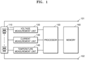
- FIG. 1 schematically shows a battery pack according to embodiments of the present disclosure.
- the battery pack may include a battery module 110, a processor 150, a memory 160, a voltage measurer (e.g., voltage measurement unit) 120, a current measurer (e.g., current measurement unit) 130, and a temperature measurer (e.g., temperature measurement unit) 140.
- a voltage measurer e.g., voltage measurement unit
- a current measurer e.g., current measurement unit
- a temperature measurer e.g., temperature measurement unit
- the battery module 110 may include a plurality of battery cells 111, and the battery cells 111 may be rechargeable secondary batteries.
- the battery cells 111 may include at least one selected from among a nickel-cadmium battery, a lead acid battery, a nickel metal hydride (NiMH) battery, a lithium ion battery, a lithium polymer battery, and/or the like.
- a number and a connection method of the battery cells 111 included in the battery module 110 may be determined based on an amount of power and a voltage suitable for the battery pack.
- FIG. 1 shows, for conceptual purposes only, that the battery cells 111 included in the battery module 110 are connected to each other in series, the battery cells 111 may be connected to each other in parallel, or in series and parallel.
- FIG. 1 shows, for conceptual purposes only, that the battery pack includes one battery module 110, the battery pack may include a plurality of the battery modules 110 connected to each other in series, in parallel, or in series and in parallel.
- the battery module 110 may include only one battery cell 111.
- the battery module 110 may include a plurality of battery modules, each battery module including a plurality of battery cells 111.
- the battery pack may include a pair of pack terminals 101 and 102 to which an electrical load or a charging device may be connected.
- a corresponding aspect of an assembly defect diagnosis may be the battery pack or at least one battery module 110 included in the battery pack.
- the battery pack may include one or more switches.
- the switch(es) may be connected between the battery module 110 and one or more of the pack terminals 101 and 102 (e.g., the pack terminal 101).
- the switch may be controlled by the processor 150.
- the battery pack may further include a battery protection circuit, a fuse, a current sensor, and the like.
- An apparatus for diagnosing an assembly defect of a battery pack may include the processor 150 and the memory 160.
- the processor 150 may control the overall operation of the apparatus for diagnosing an assembly defect of a battery pack.
- the processor 150 may be implemented in a form to selectively include a processor, an application-specific integrated circuit (ASIC), a chipset, a logic circuit, a register, a communication modem, and/or a data processing device, so as to perform the operation described above.
- ASIC application-specific integrated circuit
- the processor 150 may perform arithmetic, logic, and/or input/output operations, and may execute, for example, program code stored in the memory 160.
- the processor 150 may store data in the memory 160, or may load data stored in the memory 160.
- the memory 160 may be a recording medium that is readable by the processor 150, and may include a permanent mass storage device, such as random access memory (RAM), read only memory (ROM), and a disk drive.
- the memory 160 may store an operating system and at least one program or application code.
- the memory 160 may store program code or data according to embodiments of the present disclosure.
- the data may include a charging/discharging current, terminal voltage, and/or temperature of a battery.
- the memory 160 may store program code for estimating a state of charge (SOC) of a battery by using data generated by measuring at least one parameter of the battery module 110, and may store SOC-open circuit voltage (OCV) data.
- the memory 160 may store program code or data for estimating a state of health (SOH) of a battery by using data generated by measuring at least one parameter of the battery module 110.
- SOH state of health
- the SOH of the battery may indicate a deterioration state of the battery.
- At least one parameter of the battery module 110 may include a component or variable, such as a terminal voltage, charging/discharging current, and/or ambient temperature of the battery module 110.
- the apparatus for diagnosing an assembly defect of a battery pack may further include the voltage measurer 120, the current measurer 130, and the temperature measurer 140 for measuring at least one parameter of the battery module 110.
- the apparatus for diagnosing an assembly defect of a battery pack may further include a communication module for communicating with other devices, such as an electronic control device of a vehicle, a controller of a charging device, and the like.
- the voltage measurer 120 may be configured to measure a voltage of the battery module 110.
- the voltage measurer 120 may be electrically connected to both ends of the battery module 110 and/or the battery cell 111.
- the voltage measurer 120 may be electrically connected to the processor 150 to transmit and receive electrical signals.
- the voltage measurer 120 may measure a voltage of both ends of the battery module 110 and/or the battery cell 111 at a time interval under the control by the processor 150, and may output a signal indicating a magnitude of the measured voltage to the processor 150.
- the processor 150 may determine the voltage of the battery module 110 and/or the battery cell 111 from the signal output from the voltage measurer 120.
- the voltage measurer 120 may be implemented by using a voltage measurement circuit.
- the current measurer 130 may be configured to measure a current of a battery.
- the current measurer 130 may be electrically connected to a current sensor provided on a charging/discharging path of the battery module 110 and/or the battery cell 111.
- the current measurer 130 may be electrically connected to the processor 150 to transmit and to receive electrical signals.
- the current measurer 130 may repeatedly measure a magnitude of a charging current or a discharging current of the battery module 110 and/or the battery cell 111 at a time interval under the control by the processor 150, and may output a signal indicating the magnitude of the measured current to the processor 150.
- the processor 150 may determine the magnitude of the current from the signal output from the current measurer 130.
- the current sensor may be implemented by using a Hall sensor or sense a resistor.
- the temperature measurer 140 may be configured to measure a temperature of a battery.
- the temperature measurer 140 may be connected to the battery module 110 and/or to the battery cell 111 to measure a temperature of a secondary battery provided in the battery module 110 and/or the battery cell 111.
- the temperature measurer 140 may be electrically connected to the processor 150 to transmit and to receive electrical signals.
- the temperature measurer 140 may repeatedly measure the temperature of the secondary battery at a time interval, and may output a signal indicating a magnitude of the measured temperature to the processor 150.
- the processor 150 may determine the temperature of the secondary battery from the signal output from the temperature measurer 140.
- the temperature measurer 140 may be implemented by using a thermocouple.
- the processor 150 may estimate an SOC of the battery module 110 by using at least one of a voltage measurement value, a current measurement value, and/or a temperature measurement value of the battery module 110, which are respectively received from the voltage measurer 120, the current measurer 130, and the temperature measurer 140.
- the SOC may be calculated as a value corresponding to a remaining amount of charge of the battery module 110 in the range of about 0% to about 100%.
- the processor 150 may estimate an SOH of the battery module 110 by using at least one of a voltage measurement value, a current measurement value, and/or a temperature measurement value of the battery module 110, which are respectively received from the voltage measurer 120, from the current measurer 130, and/or from the temperature measurer 140, and may estimate SOC data of the battery module 110.
- the SOH may be calculated as a value corresponding to a remaining amount of charge of the battery module 110 in the range of about 0% to about 100%.
- the processor 150 may estimate an SOC of the battery module 110 by integrating a charging current and a discharging current of the battery module 110. If charging or discharging of the battery module 110 starts, an initial value of the SOC of the battery module 110 may be determined by using an OCV of the battery module 110, which may have been measured before the charging or discharging of the battery module 110 starts.
- the processor 150 may include an SOC-OCV lookup table, in which an SOC is defined for each OCV, and may map an SOC corresponding to the OCV of the battery module 110 from the lookup table.
- the processor 150 may estimate an SOC of the battery module 110 by using an extended Kalman filter.
- the extended Kalman filter refers to a mathematical algorithm for adaptively estimating an SOC of a secondary battery by using a voltage, a current, and a temperature of the secondary battery.
- the SOC of the battery module 110 may also be determined by other known methods, by which the SOC may be estimated by selectively utilizing a voltage, a current, and a temperature of a secondary battery, the methods being other than the current integration method or extended Kalman filter described above.
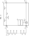
- FIG. 2 is a diagram for explaining a method of diagnosing an assembly defect of a battery pack, according to embodiments of the present disclosure.
- the battery pack may include the battery module 110 and a battery control unit (BCU) 100.
- the BCU 100 may include the processor 150, a contactor, a fuse, and a shunt resistor.
- the present disclosure is not limited thereto, and the BCU 100 according to embodiments of the present disclosure may further include a battery protection circuit, a voltage measurement circuit, a current measurement circuit, a temperature measurement circuit, and/or the like.
- the battery module 110 may be provided in the battery pack, and may include a plurality of battery cells 111.
- the BCU 100 according to embodiments of the present disclosure may be provided in the battery pack, and may control charging/discharging of the battery module 110.
- the processor 150 may calculate an internal resistance value of the battery module 110. In one or more embodiments, the processor 150 may calculate an internal resistance value of the BCU 100. In one or more embodiments, the processor 150 may diagnose an assembly defect of the battery pack by comparing a first voltage value of the battery pack with a second voltage value of the battery pack, which is a measured voltage value of the battery pack. Here, the first voltage value may be calculated based on the internal resistance value of the battery module 110 and the internal resistance value of the BCU 100.
- the processor 150 may obtain an internal resistance value measured (e.g., pre-measured) by using both ends of the battery module 110 as measurement points.
- the processor 150 may calculate the internal resistance value of the battery module 110 based on an amount of change of an internal resistance value according to a battery deterioration state, which may be stored (e.g., pre-stored) according to a model of the battery cell 111.
- the processor 150 may calculate, based on a current deterioration state, an internal resistance value of the battery pack by adding the internal resistance value of the battery module 110 and the internal resistance value of the BCU 100, the internal resistance value of the battery module 110 reflecting the amount of change of the internal resistance value according to the battery deterioration state.
- the processor 150 may calculate the first voltage value by multiplying the internal resistance value of the battery pack by a value of a current flowing through both ends of the battery pack. In one or more embodiments, the processor 150 may compare a magnitude of the first voltage value with a magnitude of the second voltage value, which may be obtained by measuring a voltage at both ends of the battery pack. If the magnitude of the second voltage value is greater than the magnitude of the first voltage value, the processor 150 may diagnose that there is an assembly defect in the battery pack.
- the processor 150 may calculate the internal resistance value of the BCU 100 based on an internal resistance value, which may be measured (e.g., pre-measured) by using measurement points (e.g., preset measurement points) for each component assembled and provided in the BCU 100.
- measurement points e.g., preset measurement points
- the battery pack may be wired to other components by welding, bolting, connecting, or the like during assembly, and thus, it may be suitable to diagnose an assembly defect of a wiring portion.
- Contact resistance of a contact portion during wiring may be expressed as internal resistance.
- 300 battery cells 111 may be provided in the battery module 110 or a battery rack.
- the battery rack may include a plurality of battery modules.
- the battery module 110 including 300 battery cells 111 may be described, but the present disclosure is not limited thereto and may be described with a battery rack including a plurality of battery modules.
- a voltage difference of about 9 V may occur in a battery module if about 300 A flows, but if an assembly defect occurs in the contact portion, a voltage difference of about 9 V or more may occur.
- a voltage difference of about 9 V or more may occur.
- a voltage value calculated by adding up all cell voltages may be a difference between a voltage value calculated by adding up all cell voltages and a voltage value measured for a battery module due to an internal resistance value.
- measurement points e.g., preset measurement points
- an internal resistance value of each component may be measured.
- internal resistance values for the components of the battery module and the BCU provided in the battery pack may be stored (e.g., pre-stored) in a memory.
- the measurement points may include the positive and negative input/output terminals 117 and 119 at respective ends of the battery module 110, positive and negative input/output terminals 101 and 102 of the battery pack, a measurement point Rack V+ between the positive input/output terminal 117 of the battery module 110 and the contactor, a measurement point Rack P+ between the fuse and the positive input/output terminal 101 of the battery pack, a measurement point Rack V- between the shunt resistor and the negative input/output terminal 102 of the battery pack, and the like.
- an internal resistance value of each component may be measured by using measurement points (e.g., preset measurement points).
- an assembly defect of each component may be detected by using a voltage value measured between measurement points (e.g., preset measurement points).
- an assembly defect of the contactor may be detected by using internal resistance and voltage values measured between the measurement point Rack V- and the measurement point Rack P+.
- FIG. 3 is a flowchart for explaining a method of diagnosing an assembly defect of a battery pack, according to embodiments of the present disclosure.
- the method of diagnosing an assembly defect of a battery pack, according to embodiments of the present disclosure may be performed by the processor 150 shown in FIG. 1 .
- the processor 150 may calculate an internal resistance value of the battery module 110 that is provided in the battery pack and that includes a plurality of battery cells 111.
- the processor 150 may obtain an internal resistance value measured (e.g., pre-measured) by using both ends of the battery module 110 as measurement points.
- the processor 150 may calculate the internal resistance value of the battery module 110 based on an amount of change of an internal resistance value according to a battery deterioration state stored (e.g., pre-stored) according to a model of the battery cell 111.
- the processor 150 may calculate an internal resistance value of the BCU 100 that is provided in the battery pack and that is configured to control charging/discharging of the battery module 110.
- the processor 150 may calculate the internal resistance value of the BCU 100 based on an internal resistance value measured (e.g., pre-measured) by using measurement points (e.g., preset measurement points) for one or more components (e.g., for each component) assembled and provided in the BCU 100.
- measurement points e.g., preset measurement points
- the processor 150 may diagnose an assembly defect of the battery pack by comparing a first voltage value of the battery pack with a second voltage value of the battery pack, the first voltage value being calculated based on the internal resistance value of the battery module 110 and the internal resistance value of the BCU 100, and the second voltage value being a measured voltage value of the battery pack.
- the processor 150 may calculate, based on a current deterioration state, an internal resistance value of the battery pack by adding the internal resistance value of the battery module 110 and the internal resistance value of the BCU 100, the internal resistance value of the battery module 110 reflecting the amount of change of the internal resistance value according to the battery deterioration state.
- the processor 150 may calculate the first voltage value by multiplying the internal resistance value of the battery pack by a value of a current flowing through both ends of the battery pack. In one or more embodiments, the processor 150 may compare a magnitude of the first voltage value with a magnitude of the second voltage value obtained by measuring a voltage at both ends of the battery pack.
- the processor 150 may diagnose that there is an assembly defect in the battery pack.
- An apparatus for diagnosing an assembly defect of a battery pack may diagnose an assembly defect of the battery pack by comparing a first voltage value of the battery pack with a second voltage value of the battery pack, the first voltage value being calculated based on the internal resistance value of the battery module 110 and the internal resistance value of the BCU 100, and the second voltage value being a measured voltage value of the battery pack.
- Q1 may represent the internal resistance value of the battery module 110
- Q2 may represent the internal resistance value of the BCU 100
- A may represent a current applied to the battery pack
- B may represent an initial current of the battery pack
- V(C) may represent a voltage of the battery pack before current application
- V(D) may represent a voltage of the battery pack 2 seconds after current application
- E may represent a rate of change of an internal resistance value according to a battery deterioration state.
- E is described in detail below.
- the apparatus for diagnosing an assembly defect of a battery pack may diagnose that there is an assembly defect in the battery pack. For example, if V 2 > V 1 , it may be diagnosed that there is an assembly defect in the battery pack, and if V 2 ⁇ V 1 , it may be diagnosed that the battery pack is normal with no detected assembly defects.
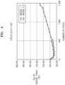
- the apparatus for diagnosing an assembly defect of a battery pack may calculate the internal resistance value of the battery module 110 based on an amount of change of an internal resistance value according to a battery deterioration state stored (e.g., pre-stored) according to a model of the battery cell 111. For example, referring to FIG. 4 , a diagram for explaining an amount of change of an internal resistance value according to a battery deterioration state, according to embodiments of the present disclosure, is shown.
- a rate of change of an internal resistance value according to a battery deterioration state may vary for each model of the battery cell 111.
- data on the rate of change of the internal resistance value according to the battery deterioration state for each model of the battery cell 111 may be stored (e.g., pre-stored) in a memory.
- a rate of change of an internal resistance value according to a battery charging/discharging cycle is shown for battery cell model 1 (MODEL 1) and battery cell model 2 (MODEL 2).
- one battery cycle may represent a cycle in which an SOC is discharged from about 100% to about 0%.
- a battery may deteriorate as a battery cycle increases, and thus, a deterioration state of the battery may be estimated based on the battery cycle.
- an internal resistance value of a battery has increased by about 130% after about 1,500 cycles.
- a rate of increase in an internal resistance value according to a battery cycle increases approximately linearly, and thus may be predicted with a trend line.
- E may be about 0.3.
- an assembly defect of a battery pack may be diagnosed more accurately.
- the various embodiments described above may be implemented in the form of a computer program executable by various components on a computer, and such a computer program may be recorded on a computer-readable medium.
- the medium may continuously store computer-executable programs, or may temporarily store the computer-executable programs for execution or downloading.
- the medium may be any one of various recording media or storage media in which a single piece or plurality of pieces of hardware are combined, and the medium is not limited to a medium directly connected to a computer system, but may be distributed on a network.
- Examples of the medium may include a magnetic medium, such as a hard disk, a floppy disk, and a magnetic tape, an optical recording medium, such as a CD-ROM and a DVD, a magneto-optical medium, such as a floptical disk, and ROM, RAM, a flash memory, and the like, which are configured to store program instructions.
- Other examples of the medium may include a recording medium and a storage medium managed by application stores distributing applications or by websites, servers, and the like supplying or distributing other various types of software.
- the term “unit” or “module” may be a hardware component, such as a processor or a circuit, and/or a software component that is executed by a hardware component, such as a processor.
- the "unit” or “module” may be implemented by components, such as software components, object-oriented software components, class components, and task components, processes, functions, attributes, procedures, subroutines, segments of program code, drivers, firmware, micro code, circuits, data, a database, data structures, tables, arrays, and variables.
- a method, computer program, and apparatus for diagnosing an assembly defect of a battery which may effectively diagnose an assembly defect in a process of diagnosing an assembly defect of a battery pack, may be provided.
- the scope of the present disclosure is not limited by this effect.
Landscapes
- Physics & Mathematics (AREA)
- General Physics & Mathematics (AREA)
- Engineering & Computer Science (AREA)
- Power Engineering (AREA)
- Manufacturing & Machinery (AREA)
- General Chemical & Material Sciences (AREA)
- Electrochemistry (AREA)
- Chemical Kinetics & Catalysis (AREA)
- Chemical & Material Sciences (AREA)
- Life Sciences & Earth Sciences (AREA)
- Mechanical Engineering (AREA)
- Transportation (AREA)
- Sustainable Energy (AREA)
- Sustainable Development (AREA)
- Microelectronics & Electronic Packaging (AREA)
- Secondary Cells (AREA)
- Charge And Discharge Circuits For Batteries Or The Like (AREA)
- Tests Of Electric Status Of Batteries (AREA)
Applications Claiming Priority (1)
| Application Number | Priority Date | Filing Date | Title |
|---|---|---|---|
| KR1020230108262A KR20250027024A (ko) | 2023-08-18 | 2023-08-18 | 배터리 팩의 조립 불량을 진단하는 방법 및 장치 |
Publications (1)
| Publication Number | Publication Date |
|---|---|
| EP4510418A1 true EP4510418A1 (de) | 2025-02-19 |
Family
ID=90880554
Family Applications (1)
| Application Number | Title | Priority Date | Filing Date |
|---|---|---|---|
| EP24172146.3A Pending EP4510418A1 (de) | 2023-08-18 | 2024-04-24 | Verfahren und vorrichtung zur diagnose einer defekten batteriepackanordnung |
Country Status (5)
| Country | Link |
|---|---|
| US (1) | US20250062423A1 (de) |
| EP (1) | EP4510418A1 (de) |
| JP (1) | JP2025028761A (de) |
| KR (1) | KR20250027024A (de) |
| CN (1) | CN119493032A (de) |
Citations (2)
| Publication number | Priority date | Publication date | Assignee | Title |
|---|---|---|---|---|
| US20200052352A1 (en) * | 2017-11-29 | 2020-02-13 | Lg Chem, Ltd. | Battery Pack |
| CN113711068A (zh) * | 2019-07-22 | 2021-11-26 | 株式会社Lg新能源 | 电池电阻诊断装置和方法 |
Family Cites Families (3)
| Publication number | Priority date | Publication date | Assignee | Title |
|---|---|---|---|---|
| US8219333B2 (en) * | 2010-06-29 | 2012-07-10 | O2Micro, Inc | Battery management systems for protecting batteries from fault conditions |
| KR20150029204A (ko) * | 2013-09-09 | 2015-03-18 | 삼성에스디아이 주식회사 | 배터리 팩, 배터리 팩을 포함하는 장치, 및 배터리 팩의 관리 방법 |
| TW201531725A (zh) * | 2014-02-11 | 2015-08-16 | Hon Hai Prec Ind Co Ltd | 電池內阻估測方法及裝置 |
-
2023
- 2023-08-18 KR KR1020230108262A patent/KR20250027024A/ko active Pending
- 2023-12-21 US US18/393,336 patent/US20250062423A1/en active Pending
-
2024
- 2024-04-24 EP EP24172146.3A patent/EP4510418A1/de active Pending
- 2024-07-17 JP JP2024114092A patent/JP2025028761A/ja active Pending
- 2024-08-12 CN CN202411098174.6A patent/CN119493032A/zh active Pending
Patent Citations (2)
| Publication number | Priority date | Publication date | Assignee | Title |
|---|---|---|---|---|
| US20200052352A1 (en) * | 2017-11-29 | 2020-02-13 | Lg Chem, Ltd. | Battery Pack |
| CN113711068A (zh) * | 2019-07-22 | 2021-11-26 | 株式会社Lg新能源 | 电池电阻诊断装置和方法 |
Also Published As
| Publication number | Publication date |
|---|---|
| US20250062423A1 (en) | 2025-02-20 |
| KR20250027024A (ko) | 2025-02-25 |
| CN119493032A (zh) | 2025-02-21 |
| JP2025028761A (ja) | 2025-03-03 |
Similar Documents
| Publication | Publication Date | Title |
|---|---|---|
| US10782350B2 (en) | Apparatus and method for diagnosing failure of switch element | |
| CN104237795B (zh) | 通过相同电压传感器测量多个电池单元的失衡探测 | |
| CN102105808B (zh) | 电池单元诊断系统和方法 | |
| US9688159B2 (en) | Methods, apparatus, and systems for preventing over-temperature battery operation | |
| US20230296688A1 (en) | Battery Diagnosing Apparatus and Method | |
| CN113661401B (zh) | 用于诊断电池组中的电池模块的状态的设备和方法 | |
| KR102889693B1 (ko) | 배터리 진단 장치, 배터리 관리 시스템, 배터리 팩, 전기 차량 및 배터리 진단 방법 | |
| Ma et al. | Faulty characteristics and identification of increased connecting and internal resistance in parallel-connected lithium-ion battery pack for electric vehicles | |
| CN107923942A (zh) | 用于监测电池组中的多个电池单体的状态的方法 | |
| KR101486626B1 (ko) | 절연 저항 검출 장치 및 이의 진단 장치 | |
| JPWO2020158182A1 (ja) | 電池制御装置 | |
| JP2018197708A (ja) | 電流計測回路の故障判断装置 | |
| CN115047361A (zh) | 一种基于序列相似度的电池内短路在线诊断方法 | |
| JP7100151B2 (ja) | 電池制御装置 | |
| KR20130126128A (ko) | 배터리의 저항측정방법 및 장치, 이를 이용한 배터리 관리 시스템 | |
| US20250192254A1 (en) | Battery management system, battery pack, electric vehicle, and battery management method | |
| Banaei et al. | Real time condition monitoring in Li-Ion batteries via battery impulse response | |
| KR101498763B1 (ko) | 절연 저항 검출 장치 및 이의 진단 장치 | |
| CN118889629B (zh) | 放电控制方法、电池管理系统和用电装置 | |
| EP4510418A1 (de) | Verfahren und vorrichtung zur diagnose einer defekten batteriepackanordnung | |
| EP4401272B1 (de) | Batterievorrichtung, batteriesystem und diagnoseverfahren | |
| US20240322268A1 (en) | Energy storage apparatus, and method of diagnosing failure of current interruption device | |
| Xu et al. | Design and study on the state of charge estimation for lithium-ion battery pack in electric vehicle | |
| Nilesh et al. | Estimation of automotive li-ion battery parameters using {MATLAB} simulink | |
| KR20210061100A (ko) | 배터리 장치 및 드리프트 오류 진단 방법 |
Legal Events
| Date | Code | Title | Description |
|---|---|---|---|
| PUAI | Public reference made under article 153(3) epc to a published international application that has entered the european phase |
Free format text: ORIGINAL CODE: 0009012 |
|
| STAA | Information on the status of an ep patent application or granted ep patent |
Free format text: STATUS: REQUEST FOR EXAMINATION WAS MADE |
|
| 17P | Request for examination filed |
Effective date: 20240424 |
|
| AK | Designated contracting states |
Kind code of ref document: A1 Designated state(s): AL AT BE BG CH CY CZ DE DK EE ES FI FR GB GR HR HU IE IS IT LI LT LU LV MC ME MK MT NL NO PL PT RO RS SE SI SK SM TR |