EP4510401A1 - Temperature abnormality detection device - Google Patents
Temperature abnormality detection device Download PDFInfo
- Publication number
- EP4510401A1 EP4510401A1 EP24216251.9A EP24216251A EP4510401A1 EP 4510401 A1 EP4510401 A1 EP 4510401A1 EP 24216251 A EP24216251 A EP 24216251A EP 4510401 A1 EP4510401 A1 EP 4510401A1
- Authority
- EP
- European Patent Office
- Prior art keywords
- infrared temperature
- temperature
- temperature sensor
- detection device
- panel
- Prior art date
- Legal status (The legal status is an assumption and is not a legal conclusion. Google has not performed a legal analysis and makes no representation as to the accuracy of the status listed.)
- Pending
Links
Images




Classifications
-
- G—PHYSICS
- G01—MEASURING; TESTING
- G01J—MEASUREMENT OF INTENSITY, VELOCITY, SPECTRAL CONTENT, POLARISATION, PHASE OR PULSE CHARACTERISTICS OF INFRARED, VISIBLE OR ULTRAVIOLET LIGHT; COLORIMETRY; RADIATION PYROMETRY
- G01J5/00—Radiation pyrometry, e.g. infrared or optical thermometry
-
- G—PHYSICS
- G01—MEASURING; TESTING
- G01J—MEASUREMENT OF INTENSITY, VELOCITY, SPECTRAL CONTENT, POLARISATION, PHASE OR PULSE CHARACTERISTICS OF INFRARED, VISIBLE OR ULTRAVIOLET LIGHT; COLORIMETRY; RADIATION PYROMETRY
- G01J5/00—Radiation pyrometry, e.g. infrared or optical thermometry
- G01J5/0096—Radiation pyrometry, e.g. infrared or optical thermometry for measuring wires, electrical contacts or electronic systems
-
- G—PHYSICS
- G01—MEASURING; TESTING
- G01J—MEASUREMENT OF INTENSITY, VELOCITY, SPECTRAL CONTENT, POLARISATION, PHASE OR PULSE CHARACTERISTICS OF INFRARED, VISIBLE OR ULTRAVIOLET LIGHT; COLORIMETRY; RADIATION PYROMETRY
- G01J5/00—Radiation pyrometry, e.g. infrared or optical thermometry
- G01J5/02—Constructional details
- G01J5/0205—Mechanical elements; Supports for optical elements
-
- G—PHYSICS
- G01—MEASURING; TESTING
- G01J—MEASUREMENT OF INTENSITY, VELOCITY, SPECTRAL CONTENT, POLARISATION, PHASE OR PULSE CHARACTERISTICS OF INFRARED, VISIBLE OR ULTRAVIOLET LIGHT; COLORIMETRY; RADIATION PYROMETRY
- G01J5/00—Radiation pyrometry, e.g. infrared or optical thermometry
- G01J5/02—Constructional details
- G01J5/027—Constructional details making use of sensor-related data, e.g. for identification of sensor parts or optical elements
-
- G—PHYSICS
- G01—MEASURING; TESTING
- G01J—MEASUREMENT OF INTENSITY, VELOCITY, SPECTRAL CONTENT, POLARISATION, PHASE OR PULSE CHARACTERISTICS OF INFRARED, VISIBLE OR ULTRAVIOLET LIGHT; COLORIMETRY; RADIATION PYROMETRY
- G01J5/00—Radiation pyrometry, e.g. infrared or optical thermometry
- G01J5/02—Constructional details
- G01J5/04—Casings
- G01J5/041—Mountings in enclosures or in a particular environment
-
- G—PHYSICS
- G01—MEASURING; TESTING
- G01J—MEASUREMENT OF INTENSITY, VELOCITY, SPECTRAL CONTENT, POLARISATION, PHASE OR PULSE CHARACTERISTICS OF INFRARED, VISIBLE OR ULTRAVIOLET LIGHT; COLORIMETRY; RADIATION PYROMETRY
- G01J5/00—Radiation pyrometry, e.g. infrared or optical thermometry
- G01J5/02—Constructional details
- G01J5/04—Casings
- G01J5/046—Materials; Selection of thermal materials
-
- G—PHYSICS
- G01—MEASURING; TESTING
- G01J—MEASUREMENT OF INTENSITY, VELOCITY, SPECTRAL CONTENT, POLARISATION, PHASE OR PULSE CHARACTERISTICS OF INFRARED, VISIBLE OR ULTRAVIOLET LIGHT; COLORIMETRY; RADIATION PYROMETRY
- G01J5/00—Radiation pyrometry, e.g. infrared or optical thermometry
- G01J5/10—Radiation pyrometry, e.g. infrared or optical thermometry using electric radiation detectors
-
- G—PHYSICS
- G01—MEASURING; TESTING
- G01J—MEASUREMENT OF INTENSITY, VELOCITY, SPECTRAL CONTENT, POLARISATION, PHASE OR PULSE CHARACTERISTICS OF INFRARED, VISIBLE OR ULTRAVIOLET LIGHT; COLORIMETRY; RADIATION PYROMETRY
- G01J5/00—Radiation pyrometry, e.g. infrared or optical thermometry
- G01J5/52—Radiation pyrometry, e.g. infrared or optical thermometry using comparison with reference sources, e.g. disappearing-filament pyrometer
- G01J5/56—Electrical features thereof
-
- H—ELECTRICITY
- H02—GENERATION; CONVERSION OR DISTRIBUTION OF ELECTRIC POWER
- H02B—BOARDS, SUBSTATIONS OR SWITCHING ARRANGEMENTS FOR THE SUPPLY OR DISTRIBUTION OF ELECTRIC POWER
- H02B1/00—Frameworks, boards, panels, desks, casings; Details of substations or switching arrangements
- H02B1/015—Boards, panels, desks; Parts thereof or accessories therefor
- H02B1/04—Mounting thereon of switches or of other devices in general, the switch or device having, or being without, casing
-
- H—ELECTRICITY
- H02—GENERATION; CONVERSION OR DISTRIBUTION OF ELECTRIC POWER
- H02B—BOARDS, SUBSTATIONS OR SWITCHING ARRANGEMENTS FOR THE SUPPLY OR DISTRIBUTION OF ELECTRIC POWER
- H02B1/00—Frameworks, boards, panels, desks, casings; Details of substations or switching arrangements
- H02B1/20—Bus-bar or other wiring layouts, e.g. in cubicles, in switchyards
- H02B1/202—Cable lay-outs
-
- H—ELECTRICITY
- H02—GENERATION; CONVERSION OR DISTRIBUTION OF ELECTRIC POWER
- H02B—BOARDS, SUBSTATIONS OR SWITCHING ARRANGEMENTS FOR THE SUPPLY OR DISTRIBUTION OF ELECTRIC POWER
- H02B1/00—Frameworks, boards, panels, desks, casings; Details of substations or switching arrangements
- H02B1/24—Circuit arrangements for boards or switchyards
-
- H—ELECTRICITY
- H02—GENERATION; CONVERSION OR DISTRIBUTION OF ELECTRIC POWER
- H02B—BOARDS, SUBSTATIONS OR SWITCHING ARRANGEMENTS FOR THE SUPPLY OR DISTRIBUTION OF ELECTRIC POWER
- H02B1/00—Frameworks, boards, panels, desks, casings; Details of substations or switching arrangements
- H02B1/26—Casings; Parts thereof or accessories therefor
- H02B1/30—Cabinet-type casings; Parts thereof or accessories therefor
- H02B1/32—Mounting of devices therein
-
- H—ELECTRICITY
- H02—GENERATION; CONVERSION OR DISTRIBUTION OF ELECTRIC POWER
- H02B—BOARDS, SUBSTATIONS OR SWITCHING ARRANGEMENTS FOR THE SUPPLY OR DISTRIBUTION OF ELECTRIC POWER
- H02B13/00—Arrangement of switchgear in which switches are enclosed in, or structurally associated with, a casing, e.g. cubicle
- H02B13/02—Arrangement of switchgear in which switches are enclosed in, or structurally associated with, a casing, e.g. cubicle with metal casing
- H02B13/035—Gas-insulated switchgear
- H02B13/065—Means for detecting or reacting to mechanical or electrical defects
-
- H—ELECTRICITY
- H02—GENERATION; CONVERSION OR DISTRIBUTION OF ELECTRIC POWER
- H02B—BOARDS, SUBSTATIONS OR SWITCHING ARRANGEMENTS FOR THE SUPPLY OR DISTRIBUTION OF ELECTRIC POWER
- H02B3/00—Apparatus specially adapted for the manufacture, assembly, or maintenance of boards or switchgear
Definitions
- the present disclosure relates to a temperature abnormality detection device that detects a temperature abnormality in equipment disposed in a panel.
- the electric facility temperature monitoring device includes two temperature detectors each disposed a cubicle in which an electric facility is housed. Each of the temperature detectors is held by a holding unit together with a lens.
- each temperature detector is connected in parallel to a controller. Therefore, with a structure where each temperature detector and the controller are connected by wiring, when a position where each temperature detector is disposed is away from the controller or a third temperature detector is added, the amount of wiring increases, and it may be difficult to reduce a size.
- an object of the present disclosure to provide a temperature abnormality detection device that is compact in size and is capable of detecting a temperature abnormality over a wide range.
- a temperature abnormality detection device that detects a temperature abnormality in equipment disposed in a panel, includes:
- the plurality of infrared temperature sensors are connected to each other by the crossover wiring. With such a configuration, an amount of wiring in the panel can be reduces. Thus, it is possible to provide a temperature abnormality detection device that is compact in size and is capable of detecting a temperature abnormality over a wide range.
- a temperature abnormality detection device 10 is applicable to, for example, a panel 1 shown in Fig. 1 .
- the panel 1 includes a casing 2 having an opening 5, a cover 3 capable of opening and closing the opening 5, and equipment 4 disposed in the casing 2.
- the cover 3 and crossover wiring 13 to be described later are not shown.
- the casing 2 has an approximately cuboid shape, and the opening 5 has an approximately rectangular shape.
- a housing part 6 is provided inside the casing 2.
- the equipment 4 and the temperature abnormality detection device 10 are housed in the housing part 6.
- the casing 2 and the cover 3 are made of a magnetic material, for example.
- the temperature abnormality detection device 10 includes a plurality of infrared temperature sensors (in this embodiment, a first infrared temperature sensor 111 and a second infrared temperature sensor 112) and a device body 12.
- each of the infrared temperature sensors 111, 112 is disposed to be capable of detecting temperature in a mutually different detection area 51, 52 of the equipment 4.
- the infrared temperature sensors 111, 112 are connected to each other by the crossover wiring 13.
- the first infrared temperature sensor 111 disposed near the device body 12 is attached to the casing 2 to be capable of detecting temperature of wiring 41 connecting components in the equipment 4.
- the second infrared temperature sensor 112 disposed away from the device body 12 is attached to the cover 3 to be capable of detecting temperature of a surface of the equipment 4 facing the cover 3.
- the first infrared temperature sensor 111 is connected to the device body 12 and a power supply 101 by the crossover wiring 13. Further, the second infrared temperature sensor 112 is connected to the first infrared temperature sensor 111 by the crossover wiring 13.
- each of the infrared temperature sensors 111, 112 includes, as an example, a lens of an optical system, a temperature conversion element, an AD converter, a temperature correction unit, and a communication unit.
- the temperature conversion element converts an infrared ray emitted from the detection area through the lens into a temperature.
- the AD converter converts the converted temperature (analog signal) into a digital signal, and the correction unit corrects an error generated when the converted temperature is converted into the digital signal.
- One end of wiring is connected to the communication unit.
- the digital signal converted by the AD converter is output from the communication unit to the device body 12 through the wiring.
- Each of the detection areas 51, 52 is preset depending on, for example, a design of the equipment 4.
- the first detection area 51 of the first infrared temperature sensor 111 includes the wiring 41 connecting the components in the equipment 4
- the second detection area 52 of the second infrared temperature sensor 112 includes a portion 42 of the surface of the equipment 4 facing the cover 3.
- the device body 12 includes a processor such as a CPU that performs computation and the like, a storage medium such as a ROM or a RAM that stores a program or data necessary for detecting a temperature abnormality in the detection areas 51, 52, and a communication unit responsible for input and output of signals from and to a programmable logic controller (PLC) 100 and the infrared temperature sensors 111, 112.
- a processor such as a CPU that performs computation and the like
- a storage medium such as a ROM or a RAM that stores a program or data necessary for detecting a temperature abnormality in the detection areas 51, 52
- PLC programmable logic controller
- the device body 12 includes a temperature abnormality determination unit 121.
- the temperature abnormality determination unit 121 is a function implemented by the processor of the device body 12 executing a predetermined program.
- the temperature abnormality determination unit 121 determines that the temperature in the detection areas 51, 52 is abnormal when the temperature in the detection areas 51, 52 detected by each of the infrared temperature sensors 111, 112 is higher than a reference temperature.
- the reference temperature is preset depending on for example, the equipment 4 and the detection areas 51, 52. According to this embodiment, when it is determined that a temperature in each of the detection areas 51, 52 is abnormal, the temperature abnormality determination unit 121 outputs to the PLC 100 a temperature abnormality signal indicating that the temperature in each of the detection areas 51, 52 is abnormal.
- a connection between the device body 12 and the PLC 100 may be radio connection or wire connection.
- the infrared temperature sensors 111, 112 will be described in more detail with reference to Figs. 4 to 6 .
- the first infrared temperature sensor 111 and the second infrared temperature sensor 112 are identical to each other in size and shape. Therefore, a description of the second infrared temperature sensor 112 will be omitted by a support of the description of the first infrared temperature sensor 111.
- the first infrared temperature sensor 111 which has an approximately rectangular plate shape, includes a detection surface 113 on which a temperature detector 115 is provided, an attachment surface 114 attachable to and detachable from an inner surface of the panel 1 (that is, the casing 2 and the cover 3), and a connection surface 116 to which the crossover wiring 13 is connected.
- the detection surface 113 and the attachment surface 114 are arranged side by side in a thickness direction of the first infrared temperature sensor 111.
- the connection surface 116 extends in a direction intersecting the detection surface 113 and the attachment surface 114.
- the connection surface 116 is provided with a connection terminal 117 to which the crossover wiring 13 can be connected.
- the attachment surface 114 of the first infrared temperature sensor 111 and the inner surface of the panel 1 are connected by an attachment fitting 30 shown in Figs. 5 and 6 .
- the temperature abnormality detection device 10 further includes the attachment fitting 30 that detachably attaches the attachment surface 114 of the first infrared temperature sensor 111 to the inner surface of the panel 1.
- the attachment fitting 30, which has an approximately rectangular plate shape, includes a pair of rail portions 31 extending in parallel along a length direction of the attachment fitting 30.
- the attachment surface 114 is provided with a rail attachment portion 14 to which the pair of rail portions 31 can be attached.
- the rail attachment portion 14 is configured by four locking portions 15 provided at four corners of the attachment surface 114.
- Each of the locking portions 15 is disposed capable of insetting the attachment fitting 30 between the adjacent rail attachment portions 14 and disposed to provide a gap between the locking portions 15 and the attachment surface 114.
- the attachment fitting 30 is attachable to the attachment surface 114 with its length direction extending in a width direction of the attachment surface 114.
- the attachment surface 114 is also attachable with its length direction extending in a length direction of the attachment surface 114.
- a permanent magnet 32 is provided between the pair of rail portions 31.
- the attachment fitting 30 is detachably attached to the inner surface of the panel 1 by the permanent magnet 32.
- the plurality of infrared temperature sensors 111, 112 are connected to each other by the crossover wiring 13. With such a configuration, an amount of wiring in the panel 1 can be reduces. Thus, it is possible to realize the temperature abnormality detection device 10 that is compact in size and is capable of detecting a temperature abnormality over a wide range. With such a configuration, an infrared temperature sensor can be added easily.
- the first infrared temperature sensor 111 includes the attachment surface 114 attachable to and detachable from the inner surface of the panel 1, and the connection surface 116 that extends in a direction intersecting the attachment surface 114 and to which the crossover wiring 13 is connected. With such a configuration, a thickness of the first infrared temperature sensor 111 can be reduced. Accordingly, when the first infrared temperature sensor 111 is attached to the inner surface of the panel 1, a distance between the first infrared temperature sensor 111 and the detection area 51 is secured , so that a range, where the first infrared temperature sensor 111 can detect temperature, can be widened.
- the temperature abnormality detection device 10 further includes the attachment fitting 30 that detachably attaches the attachment surface 114 of the first infrared temperature sensor 111 to the inner surface of the panel 1.
- the attachment fitting 30 includes the pair of rail portions 31 extending in parallel, and the attachment surface 114 includes the rail attachment portion 14 to which the pair of rail portions 31 is attachable. With such a configuration, a position where the attachment fitting 30 is attached to the attachment surface 114 can be easily changed depending on, for example, a place where the first infrared temperature sensor 111 is disposed. Thus, the first infrared temperature sensor 111 can be easily attached to the inner surface of the panel 1.
- the attachment fitting 30 further includes the permanent magnet 32 and is attached to the inner surface of the panel 1 by the permanent magnet 32.
- the first infrared temperature sensor 111 can be easily attached to even a position where, for example, mechanical fixing such as by a screw is difficult.
- each of the infrared temperature sensors 111, 112 can detect temperature in the mutually different detection area 51, 52 of the equipment 4, the infrared temperature sensors 111, 112 can have any shape and structure.
- each of the infrared temperature sensors 111, 112 may have a shape other than an approximately cuboid shape, and may be attached to the inner surface of the panel 1 by a fastening member such as an adhesive or a screw instead of the attachment fitting 30.
- each of the infrared temperature sensors 111, 112 may be disposed not only inside the panel 1 but also outside the panel 1.
- the temperature abnormality detection device 10 shown in Fig. 7 is configured that the second infrared temperature sensor 112 detects the temperature in the second detection area 52 via a through hole 301 provided through the cover 3.
- each of the infrared temperature sensors 111, 112 can be disposed at a position where a temperature abnormality in the detection area can be detected with higher reliability.
- a camera (not shown) may be used.
- the camera is configured to image the detection areas 51, 52, and includes the rail attachment portion 14 to which the attachment fitting 30 is attachable, as with the infrared temperature sensors 111, 112.
- the positioning of each of the infrared temperature sensors 111, 112 using the camera is made as follows. First, the attachment fitting 30 is attached to the camera. Then, the camera is moved to a detection position where the detection areas 51, 52 for detecting temperature is included in an imaging area of the camera.
- each infrared temperature sensor 111 is positioned at the detection position. That is, the infrared temperature sensors 111, 112 can be accurately positioned using the camera without using the infrared temperature sensors 111, 112 having a camera built therein.
- a temperature abnormality detection device 10 that detects a temperature abnormality in equipment 4 disposed in a panel 1 includes:
- the plurality of infrared temperature sensors 111, 112 is connected to each other by the crossover wiring 13. With such a configuration, an amount of wiring in the panel 1 can be reduces. Thus, it is possible to realize the temperature abnormality detection device 10 that is compact in size and is capable of detecting a temperature abnormality over a wide range. With such a configuration, an infrared temperature sensor can be added easily.
- a thickness of the first infrared temperature sensor 111 can be reduced. Accordingly, when the first infrared temperature sensor 111 is attached to the inner surface of the panel 1, a distance between the first infrared temperature sensor 111 and the detection area 51 is secured, so that a range, where the first infrared temperature sensor 111 can detect temperature, can be widened.
- a temperature abnormality detection device 10 according to a third aspect of the present disclosure further includes
- a position where the attachment fitting 30 is attached to the attachment surface 114 can be easily changed depending on, for example, a place where the first infrared temperature sensor 111 is disposed.
- the first infrared temperature sensor 111 can be easily attached to the inner surface of the panel 1.
- a temperature abnormality detection device 10 according to a fourth aspect of the present disclosure further includes
- each of the infrared temperature sensors 111, 112 can be accurately positioned using the camera, without using infrared temperature sensors 111, 112 each having a camera built therein.
- the first infrared temperature sensor 111 can be easily attached to even a position where, for example, mechanical fixing such as by a screw is difficult.
- At least one of the plurality of infrared temperature sensors 111, 112 is disposed capable of detecting outside the panel 1 the temperature in the detection area 51, 52 via a through hole 301 of the panel 1.
- each of the infrared temperature sensors 111, 112 can be disposed at a position where a temperature abnormality in the detection area can be detected with higher reliability.
- the temperature abnormality detection device is applicable to, for example, a control panel, a distribution panel, or a high-voltage power receiving panel.
Landscapes
- Physics & Mathematics (AREA)
- General Physics & Mathematics (AREA)
- Spectroscopy & Molecular Physics (AREA)
- Engineering & Computer Science (AREA)
- Power Engineering (AREA)
- Manufacturing & Machinery (AREA)
- Radiation Pyrometers (AREA)
- Measuring Temperature Or Quantity Of Heat (AREA)
- Gas-Insulated Switchgears (AREA)
Abstract
Description
- The present disclosure relates to a temperature abnormality detection device that detects a temperature abnormality in equipment disposed in a panel.
-
PTL 1 discloses an electric facility temperature monitoring device. The electric facility temperature monitoring device includes two temperature detectors each disposed a cubicle in which an electric facility is housed. Each of the temperature detectors is held by a holding unit together with a lens. - In the electric facility temperature monitoring device, each temperature detector is connected in parallel to a controller. Therefore, with a structure where each temperature detector and the controller are connected by wiring, when a position where each temperature detector is disposed is away from the controller or a third temperature detector is added, the amount of wiring increases, and it may be difficult to reduce a size.
- It is, therefore, an object of the present disclosure to provide a temperature abnormality detection device that is compact in size and is capable of detecting a temperature abnormality over a wide range.
- A temperature abnormality detection device that detects a temperature abnormality in equipment disposed in a panel, includes:
- a plurality of infrared temperature sensors each capable of detecting temperature in a mutually different detection area of the equipment; and
- a device body including a temperature abnormality determination unit that determines that the temperature in the detection area detected by each of the plurality of infrared temperature sensors is abnormal when the temperature in the detection area is higher than a reference temperature, wherein
- the plurality of infrared temperature sensors is connected to each other by crossover wiring.
- According to the temperature abnormality detection device, the plurality of infrared temperature sensors are connected to each other by the crossover wiring. With such a configuration, an amount of wiring in the panel can be reduces. Thus, it is possible to provide a temperature abnormality detection device that is compact in size and is capable of detecting a temperature abnormality over a wide range.
-
-
Fig. 1 is a front view of a panel showing an application example of a temperature abnormality detection device according to an embodiment of the present disclosure. -
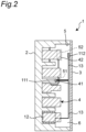
Fig. 2 is a cross-sectional view taken along a line II-II inFig. 1 . -
Fig. 3 is a block diagram showing a structure of the temperature abnormality detection device according to the embodiment of the present disclosure. -
Fig. 4 is a perspective view of an infrared temperature sensor of the temperature abnormality detection device shown inFig. 3 . -
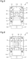
Fig. 5 is a first rear view of the infrared temperature sensor of the temperature abnormality detection device shown inFig. 3 . -
Fig. 6 is a first rear view of the infrared temperature sensor of the temperature abnormality detection device shown inFig. 3 . -
Fig. 7 is a partial cross-sectional view of a modification of the temperature abnormality detection device shown inFig. 3 . - Hereinafter, a description will be given of an example of the present disclosure with reference to the accompanying drawings. Note that, in the following description, terms representing specific directions or positions (for example, terms including "up", "down", "right", and "left") will be used as necessary, but the use of these terms is intended to facilitate understanding of the present disclosure with reference to the drawings, and the technical scope of the present disclosure shall not be limited by the meanings of the terms. Further, the following description shows merely an example in nature and is not intended to limit the present disclosure, applications of the present disclosure, or uses of the present disclosure. Furthermore, the drawings are schematic drawings, and ratios between dimensions are not necessarily equal to the actual ratios.
- A temperature
abnormality detection device 10 according to an embodiment of the present disclosure is applicable to, for example, apanel 1 shown inFig. 1 . As shown inFig. 2 , thepanel 1 includes acasing 2 having anopening 5, acover 3 capable of opening and closing theopening 5, andequipment 4 disposed in thecasing 2. InFig. 1 , thecover 3 andcrossover wiring 13 to be described later are not shown. - As an example, the
casing 2 has an approximately cuboid shape, and theopening 5 has an approximately rectangular shape. As shown inFig. 2 , ahousing part 6 is provided inside thecasing 2. Theequipment 4 and the temperatureabnormality detection device 10 are housed in thehousing part 6. Thecasing 2 and thecover 3 are made of a magnetic material, for example. - As shown in
Figs. 1 and2 , the temperatureabnormality detection device 10 includes a plurality of infrared temperature sensors (in this embodiment, a firstinfrared temperature sensor 111 and a second infrared temperature sensor 112) and adevice body 12. - As shown in
Fig. 2 , each of theinfrared temperature sensors different detection area equipment 4. Theinfrared temperature sensors crossover wiring 13. - Specifically, the first
infrared temperature sensor 111 disposed near thedevice body 12 is attached to thecasing 2 to be capable of detecting temperature ofwiring 41 connecting components in theequipment 4. The secondinfrared temperature sensor 112 disposed away from thedevice body 12 is attached to thecover 3 to be capable of detecting temperature of a surface of theequipment 4 facing thecover 3. The firstinfrared temperature sensor 111 is connected to thedevice body 12 and apower supply 101 by thecrossover wiring 13. Further, the secondinfrared temperature sensor 112 is connected to the firstinfrared temperature sensor 111 by thecrossover wiring 13. - Although not shown, each of the
infrared temperature sensors device body 12 through the wiring. - Each of the
detection areas equipment 4. According to this embodiment, as an example, thefirst detection area 51 of the firstinfrared temperature sensor 111 includes thewiring 41 connecting the components in theequipment 4, and thesecond detection area 52 of the secondinfrared temperature sensor 112 includes aportion 42 of the surface of theequipment 4 facing thecover 3. - As an example, the
device body 12 includes a processor such as a CPU that performs computation and the like, a storage medium such as a ROM or a RAM that stores a program or data necessary for detecting a temperature abnormality in thedetection areas infrared temperature sensors - Specifically, as shown in
Fig.3 , thedevice body 12 includes a temperatureabnormality determination unit 121. For example, the temperatureabnormality determination unit 121 is a function implemented by the processor of thedevice body 12 executing a predetermined program. - The temperature
abnormality determination unit 121 determines that the temperature in thedetection areas detection areas infrared temperature sensors equipment 4 and thedetection areas detection areas abnormality determination unit 121 outputs to the PLC 100 a temperature abnormality signal indicating that the temperature in each of thedetection areas - A connection between the
device body 12 and thePLC 100 may be radio connection or wire connection. - Each of the
infrared temperature sensors Figs. 4 to 6 . The firstinfrared temperature sensor 111 and the secondinfrared temperature sensor 112 are identical to each other in size and shape. Therefore, a description of the secondinfrared temperature sensor 112 will be omitted by a support of the description of the firstinfrared temperature sensor 111. - As shown in
Fig. 4 , the firstinfrared temperature sensor 111, which has an approximately rectangular plate shape, includes adetection surface 113 on which atemperature detector 115 is provided, anattachment surface 114 attachable to and detachable from an inner surface of the panel 1 (that is, thecasing 2 and the cover 3), and aconnection surface 116 to which thecrossover wiring 13 is connected. Thedetection surface 113 and theattachment surface 114 are arranged side by side in a thickness direction of the firstinfrared temperature sensor 111. Theconnection surface 116 extends in a direction intersecting thedetection surface 113 and theattachment surface 114. Theconnection surface 116 is provided with aconnection terminal 117 to which thecrossover wiring 13 can be connected. - In the temperature
abnormality detection device 10, theattachment surface 114 of the firstinfrared temperature sensor 111 and the inner surface of thepanel 1 are connected by an attachment fitting 30 shown inFigs. 5 and 6 . In other words, the temperatureabnormality detection device 10 further includes the attachment fitting 30 that detachably attaches theattachment surface 114 of the firstinfrared temperature sensor 111 to the inner surface of thepanel 1. - The attachment fitting 30, which has an approximately rectangular plate shape, includes a pair of
rail portions 31 extending in parallel along a length direction of the attachment fitting 30. Theattachment surface 114 is provided with arail attachment portion 14 to which the pair ofrail portions 31 can be attached. Therail attachment portion 14 is configured by four lockingportions 15 provided at four corners of theattachment surface 114. Each of the lockingportions 15 is disposed capable of insetting the attachment fitting 30 between the adjacentrail attachment portions 14 and disposed to provide a gap between the lockingportions 15 and theattachment surface 114. When the pair ofrail portions 31 is disposed between each lockingportion 15 and theattachment surface 114, a part of the pair ofrail portions 31 is locked in a direction intersecting theattachment surface 114 by each lockingportion 15 to be attached to therail attachment portion 14. - As shown in
Fig. 5 , the attachment fitting 30 is attachable to theattachment surface 114 with its length direction extending in a width direction of theattachment surface 114. As shown inFig. 6 , theattachment surface 114 is also attachable with its length direction extending in a length direction of theattachment surface 114. - A permanent magnet 32 is provided between the pair of
rail portions 31. The attachment fitting 30 is detachably attached to the inner surface of thepanel 1 by the permanent magnet 32. - In the temperature
abnormality detection device 10, the plurality ofinfrared temperature sensors crossover wiring 13. With such a configuration, an amount of wiring in thepanel 1 can be reduces. Thus, it is possible to realize the temperatureabnormality detection device 10 that is compact in size and is capable of detecting a temperature abnormality over a wide range. With such a configuration, an infrared temperature sensor can be added easily. - The first
infrared temperature sensor 111 includes theattachment surface 114 attachable to and detachable from the inner surface of thepanel 1, and theconnection surface 116 that extends in a direction intersecting theattachment surface 114 and to which thecrossover wiring 13 is connected. With such a configuration, a thickness of the firstinfrared temperature sensor 111 can be reduced. Accordingly, when the firstinfrared temperature sensor 111 is attached to the inner surface of thepanel 1, a distance between the firstinfrared temperature sensor 111 and thedetection area 51 is secured , so that a range, where the firstinfrared temperature sensor 111 can detect temperature, can be widened. - The temperature
abnormality detection device 10 further includes the attachment fitting 30 that detachably attaches theattachment surface 114 of the firstinfrared temperature sensor 111 to the inner surface of thepanel 1. The attachment fitting 30 includes the pair ofrail portions 31 extending in parallel, and theattachment surface 114 includes therail attachment portion 14 to which the pair ofrail portions 31 is attachable. With such a configuration, a position where the attachment fitting 30 is attached to theattachment surface 114 can be easily changed depending on, for example, a place where the firstinfrared temperature sensor 111 is disposed. Thus, the firstinfrared temperature sensor 111 can be easily attached to the inner surface of thepanel 1. - The attachment fitting 30 further includes the permanent magnet 32 and is attached to the inner surface of the
panel 1 by the permanent magnet 32. With such a configuration, the firstinfrared temperature sensor 111 can be easily attached to even a position where, for example, mechanical fixing such as by a screw is difficult. - As long as each of the
infrared temperature sensors different detection area equipment 4, theinfrared temperature sensors infrared temperature sensors panel 1 by a fastening member such as an adhesive or a screw instead of the attachment fitting 30. - As shown in
Fig. 7 , each of theinfrared temperature sensors panel 1 but also outside thepanel 1. The temperatureabnormality detection device 10 shown inFig. 7 is configured that the secondinfrared temperature sensor 112 detects the temperature in thesecond detection area 52 via a throughhole 301 provided through thecover 3. With such a configuration, each of theinfrared temperature sensors - When each of the
infrared temperature sensors detection areas rail attachment portion 14 to which the attachment fitting 30 is attachable, as with theinfrared temperature sensors infrared temperature sensors detection areas infrared temperature sensors infrared temperature sensor 111 is positioned at the detection position. That is, theinfrared temperature sensors infrared temperature sensors - Although the various embodiments of the present disclosure have been described in detail with reference to the drawings, a description will be given in conclusion of various aspects of the present disclosure. Note that the following description will be given as an example with the reference numerals attached.
- A temperature
abnormality detection device 10 according to a first aspect of the present disclosure that detects a temperature abnormality inequipment 4 disposed in apanel 1 includes: - a plurality of
infrared temperature sensors different detection area equipment 4; and - a
device body 12 including a temperatureabnormality determination unit 121 that determines that the temperature in the detection are 51, 52 detected by each of the plurality ofinfrared temperature sensors detection area - the plurality of
infrared temperature sensors crossover wiring 13. - According to the temperature
abnormality detection device 10 of the first aspect, the plurality ofinfrared temperature sensors crossover wiring 13. With such a configuration, an amount of wiring in thepanel 1 can be reduces. Thus, it is possible to realize the temperatureabnormality detection device 10 that is compact in size and is capable of detecting a temperature abnormality over a wide range. With such a configuration, an infrared temperature sensor can be added easily. - In a temperature
abnormality detection device 10 according to a second aspect of the present disclosure, - the plurality of
infrared temperature sensors infrared temperature sensor 111 disposed in thepanel 1 and capable of detecting the temperature in thefirst detection area 51, and - the first
infrared temperature sensor 111 includes anattachment surface 114 attachable to and detachable from an inner surface of thepanel 1 and aconnection surface 116 to which thecrossover wiring 13 is connected, theconnection surface 116 extending in a direction intersecting theattachment surface 114. - According to the temperature
abnormality detection device 10 of the second aspect, a thickness of the firstinfrared temperature sensor 111 can be reduced. Accordingly, when the firstinfrared temperature sensor 111 is attached to the inner surface of thepanel 1, a distance between the firstinfrared temperature sensor 111 and thedetection area 51 is secured, so that a range, where the firstinfrared temperature sensor 111 can detect temperature, can be widened. - A temperature
abnormality detection device 10 according to a third aspect of the present disclosure further includes - an attachment fitting 30 that detachably attaches the
attachment surface 114 of the firstinfrared temperature sensor 111 to the inner surface of thepanel 1, wherein - the attachment fitting 30 includes a pair of
rail portions 31 extending in parallel, and - the
attachment surface 114 includes arail attachment portion 14 to which the pair ofrail portions 31 is attached. - According to the temperature
abnormality detection device 10 of the third aspect, a position where the attachment fitting 30 is attached to theattachment surface 114 can be easily changed depending on, for example, a place where the firstinfrared temperature sensor 111 is disposed. Thus, the firstinfrared temperature sensor 111 can be easily attached to the inner surface of thepanel 1. - A temperature
abnormality detection device 10 according to a fourth aspect of the present disclosure further includes - a camera capable of imaging the
detection area - the attachment fitting 30 is configured to attach any one of the plurality of
infrared temperature sensors panel 1. - According to the temperature
abnormality detection device 10 of the fourth aspect, each of theinfrared temperature sensors infrared temperature sensors - In a temperature
abnormality detection device 10 according to a fifth aspect of the present disclosure, - the attachment fitting 30 has
- a permanent magnet 32 and is attached to the inner surface of the
panel 1 by the permanent magnet 32. - According to the temperature
abnormality detection device 10 of the fifth aspect, the firstinfrared temperature sensor 111 can be easily attached to even a position where, for example, mechanical fixing such as by a screw is difficult. - In a temperature
abnormality detection device 10 according to a sixth aspect of the present disclosure,
at least one of the plurality ofinfrared temperature sensors panel 1 the temperature in thedetection area hole 301 of thepanel 1. - According to the temperature
abnormality detection device 10 of the sixth aspect, each of theinfrared temperature sensors - Note that suitably combining any of the various embodiments or any of the various modifications makes it possible to achieve effects possessed by each of the embodiments or the modifications. Further, combinations of the embodiments, combinations of the modifications, or combinations of the embodiments and the modifications are possible, and combinations of features in different embodiments or modifications are also possible.
- While the present disclosure has been fully described in connection with the preferred embodiments with reference to the accompanying drawings, it will be apparent to those skilled in the art that various changes and modifications may be made. Unless such changes and modifications depart from the scope of the present disclosure as set forth in the accompanying claims, the changes and modifications should be construed as being included within the scope of the present disclosure.
- The temperature abnormality detection device according to the present disclosure is applicable to, for example, a control panel, a distribution panel, or a high-voltage power receiving panel.
-
- 1. panel
- 2. casing
- 3. cover
- 4. equipment
- 41. wiring
- 5. opening
- 6. housing part
- 10. temperature abnormality detection device
- 111. first infrared temperature sensor
- 112. second infrared temperature sensor
- 113. detection surface
- 114. attachment surface
- 115. temperature detector
- 116. connection surface
- 117. connection terminal
- 12. device body
- 121. temperature abnormality determination unit
- 13. crossover wiring
- 14. rail attachment portion
- 15. locking portion
- 30. attachment fitting
- 31. rail portion
- 32. permanent magnet
- 51. first detection area
- 52. second detection area
- 100. PLC
- 101. power supply
- The following section comprises numbered clauses which are not claims, but are additional statements of the invention.
- 1. A temperature abnormality detection device that detects a temperature abnormality in equipment disposed in a panel, comprising:
- a plurality of infrared temperature sensors each capable of detecting temperature in a mutually different detection area of the equipment; and
- a device body including a temperature abnormality determination unit that determines that the temperature in the detection area detected by each of the plurality of infrared temperature sensors is abnormal when the temperature in the detection area is higher than a reference temperature, wherein
- the plurality of infrared temperature sensors is connected to each other by crossover wiring.
- 2. The temperature abnormality detection device according to
clause 1, wherein- the plurality of infrared temperature sensors includes a first infrared temperature sensor diposed in the panel and capable of detecting the temperature in the first detection area, and
- the first infrared temperature sensor includes an attachment surface attachable to and detachable from an inner surface of the panel and a connection surface to which the crossover wiring is connected, the connection surface extending in a direction intersecting the attachment surface.
- 3. The temperature abnormality detection device according to
clause 2, further comprising- an attachment fitting that detachably attaches the attachment surface of the first infrared temperature sensor to the inner surface of the panel, wherein
- the attachment fitting includes a pair of rail portions extending in parallel, and
- the attachment surface includes a rail attachment portion to which the pair of rail portions is attached.
- 4. The temperature abnormality detection device according to
clause 3, further comprising- a camera capable of imaging the detection area wherein
- the attachment fitting is configured to be capable of attaching any one of each of the plurality of infrared temperature sensors and the camera to the inner surface of the panel.
- 5. The temperature abnormality detection device according to
clause
the attachment fitting includes a permanent magnet and is attached to the inner surface of the panel by the permanent magnet. - 6. The temperature abnormality detection device according to any one of
clauses 1 to 5, wherein
at least one of the plurality of infrared temperature sensors is disposed capable of detecting outside the panel the temperature in the detection area via a through hole of the panel.
Claims (9)
- A temperature abnormality detection device (10) configured to detect a temperature abnormality in equipment (4) disposed in a panel (1), comprisinga plurality of infrared temperature sensors (111, 112) each configured to detect temperature in a mutually different detection area (51, 52) of the equipment (4), whereinthe plurality of infrared temperature sensors (111, 112) is connected to each other by crossover wiring (13),the plurality of infrared temperature sensors (111, 112) includes a first infrared temperature sensor (111) and a second infrared temperature sensor (112), the first infrared temperature sensor (111) being disposed in the panel (1) and configured to detect the temperature in the first detection area (51), the second infrared temperature sensor (112) being connected to the first infrared temperature sensor (111) by the crossover wiring (13), andthe first infrared temperature sensor (111) is connected to a power supply (101) by the crossover wiring (13) .
- The temperature abnormality detection device according to claim 1, wherein
the second infrared temperature sensor (112) is connected to the power supply (101) by way of the first infrared temperature sensor (111). - The temperature abnormality detection device according to claim 1 or 2, comprisinga device body (12) including a communication unit, the device body (12) being connected by the communication unit, whereinthe device body (12) is connected to the first infrared temperature sensor (111) by the crossover wiring (13) and is configured to output a temperature abnormality signal indicating that a temperature in each of the detection area (51, 52) is abnormal.
- The temperature abnormality detection device according to claim 3, whereinone end of wiring is connected to the communication unit, anda digital signal of the first infrared temperature sensor (111) is outputted from the communication unit to the device body (12) through the wiring.
- The temperature abnormality detection device according to claim 1 or 2, whereinthe panel (1) comprises a casing (2) in which the equipment (4) disposed, andthe first infrared temperature sensor (111) includes an attachment surface (114) attachable to and detachable from an inner surface of the casing (2) and a connection surface (116) to which the crossover wiring (13) is connected, the connection surface (116) extending in a direction intersecting the attachment surface (114), the connection surface (116) extending in a direction intersecting the attachment surface (114).
- The temperature abnormality detection device according to claim 5, comprisingan attachment fitting (30) configured to detachably attach the attachment surface (114) of the first infrared temperature sensor (111) to the inner surface of the casing (2),the attachment fitting (30) includes a pair of rail portions (31) extending in parallel, andthe attachment surface (114) includes a rail attachment portion (14) to which the pair of rail portions (31) is attached.
- The temperature abnormality detection device according to claim 6, wherein
the attachment fitting (30) includes a permanent magnet (32) and is attached to the inner surface of the panel (1) by the permanent magnet (32). - The temperature abnormality detection device according to claim 6, comprisinga camera configured to image the detection area (51, 52) whereinthe attachment fitting (30) is configured to attach any one of each of the plurality of infrared temperature sensors (111, 112) and the camera to the inner surface of the panel (1).
- The temperature abnormality detection device according to any one of claims 1 to 8, wherein
at least one of the plurality of infrared temperature sensors (111, 112) is disposed to detect outside the panel (1) the temperature in the detection area (51, 52) via a through hole (301) of the panel (1).
Applications Claiming Priority (3)
| Application Number | Priority Date | Filing Date | Title |
|---|---|---|---|
| JP2019077927A JP6992785B2 (en) | 2019-04-16 | 2019-04-16 | Temperature abnormality detector |
| EP20792043.0A EP3958414B1 (en) | 2019-04-16 | 2020-02-21 | Panel comprising temperature abnormality detection device |
| PCT/JP2020/007091 WO2020213256A1 (en) | 2019-04-16 | 2020-02-21 | Temperature abnormality detection device |
Related Parent Applications (2)
| Application Number | Title | Priority Date | Filing Date |
|---|---|---|---|
| EP20792043.0A Division EP3958414B1 (en) | 2019-04-16 | 2020-02-21 | Panel comprising temperature abnormality detection device |
| EP20792043.0A Division-Into EP3958414B1 (en) | 2019-04-16 | 2020-02-21 | Panel comprising temperature abnormality detection device |
Publications (1)
| Publication Number | Publication Date |
|---|---|
| EP4510401A1 true EP4510401A1 (en) | 2025-02-19 |
Family
ID=72838194
Family Applications (2)
| Application Number | Title | Priority Date | Filing Date |
|---|---|---|---|
| EP20792043.0A Active EP3958414B1 (en) | 2019-04-16 | 2020-02-21 | Panel comprising temperature abnormality detection device |
| EP24216251.9A Pending EP4510401A1 (en) | 2019-04-16 | 2020-02-21 | Temperature abnormality detection device |
Family Applications Before (1)
| Application Number | Title | Priority Date | Filing Date |
|---|---|---|---|
| EP20792043.0A Active EP3958414B1 (en) | 2019-04-16 | 2020-02-21 | Panel comprising temperature abnormality detection device |
Country Status (7)
| Country | Link |
|---|---|
| US (1) | US12498271B2 (en) |
| EP (2) | EP3958414B1 (en) |
| JP (1) | JP6992785B2 (en) |
| KR (1) | KR102615446B1 (en) |
| CN (3) | CN113615020B (en) |
| TW (1) | TWI737193B (en) |
| WO (1) | WO2020213256A1 (en) |
Families Citing this family (1)
| Publication number | Priority date | Publication date | Assignee | Title |
|---|---|---|---|---|
| KR102436651B1 (en) * | 2022-02-21 | 2022-08-26 | 주식회사 네오콘스 | Switchgear (high-voltage panel, low-voltage panel, motor control panel, distribution panel) Capable of Initial Fire Extinguishing Function and Insulation Status Monitoring |
Citations (5)
| Publication number | Priority date | Publication date | Assignee | Title |
|---|---|---|---|---|
| US5793522A (en) * | 1995-12-29 | 1998-08-11 | Comet | Observation window for checking the temperature of objects |
| US20100044567A1 (en) * | 2008-08-21 | 2010-02-25 | Brandt David D | In-cabinet thermal monitoring method and system |
| US20130250102A1 (en) * | 2011-06-10 | 2013-09-26 | Flir Systems, Inc. | Electrical cabinet infrared monitor |
| JP2016038277A (en) * | 2014-08-07 | 2016-03-22 | 株式会社東光高岳 | Electrical facility temperature monitoring device and electrical facility temperature monitoring system |
| US20170089763A1 (en) * | 2015-09-28 | 2017-03-30 | Cooper Technologies Company | Infrared Sensor Array Circuit Breaker Monitoring |
Family Cites Families (11)
| Publication number | Priority date | Publication date | Assignee | Title |
|---|---|---|---|---|
| JP4869193B2 (en) * | 2007-09-18 | 2012-02-08 | 三菱電機株式会社 | Device control system and lighting control system |
| US10775978B2 (en) * | 2014-10-03 | 2020-09-15 | Schneider Electric USA, Inc. | Electrical enclosure with built in remote inspection and virtual control of sensor placement |
| US9683895B2 (en) * | 2014-12-29 | 2017-06-20 | Bosch Automotive Service Solutions Inc. | Non-contact infrared temperature sensor with wireless functionality |
| CN106197679A (en) * | 2015-05-06 | 2016-12-07 | 北京格林吉能源科技有限公司 | Protection device for infrared temperature sensor |
| CN105811277A (en) * | 2016-04-22 | 2016-07-27 | 成都聚智工业设计有限公司 | New type electric power outgoing cubicle |
| KR200492549Y1 (en) * | 2016-04-28 | 2020-11-05 | 엘에스일렉트릭(주) | Distributing panel |
| KR101715079B1 (en) | 2016-11-11 | 2017-03-09 | 주식회사 현대콘트롤전기 | A partial discharge detection and diagnosis appratus for a distributing board with the acoustic emission sensor |
| JP2019045192A (en) * | 2017-08-30 | 2019-03-22 | 株式会社東芝 | One-line ground fault current sensor and switch gear |
| TWM558911U (en) * | 2017-11-09 | 2018-04-21 | Lin Zhi Hong | Environmental monitoring operation device and environment sensing operation monitoring equipment |
| CN207423370U (en) * | 2017-12-05 | 2018-05-29 | 张学院 | A kind of temperature on-line monitoring device of high voltage electric equipment |
| CN109506708A (en) * | 2018-11-09 | 2019-03-22 | 郑州福禄源电子科技有限公司 | A kind of high voltage electric equipment internal temperature on-line monitoring method |
-
2019
- 2019-04-16 JP JP2019077927A patent/JP6992785B2/en active Active
-
2020
- 2020-02-21 CN CN202080022568.7A patent/CN113615020B/en active Active
- 2020-02-21 EP EP20792043.0A patent/EP3958414B1/en active Active
- 2020-02-21 EP EP24216251.9A patent/EP4510401A1/en active Pending
- 2020-02-21 KR KR1020217030871A patent/KR102615446B1/en active Active
- 2020-02-21 US US17/603,417 patent/US12498271B2/en active Active
- 2020-02-21 WO PCT/JP2020/007091 patent/WO2020213256A1/en not_active Ceased
- 2020-02-21 CN CN202410254742.0A patent/CN118137299A/en active Pending
- 2020-02-21 CN CN202411004736.6A patent/CN118913452A/en active Pending
- 2020-02-26 TW TW109106129A patent/TWI737193B/en active
Patent Citations (5)
| Publication number | Priority date | Publication date | Assignee | Title |
|---|---|---|---|---|
| US5793522A (en) * | 1995-12-29 | 1998-08-11 | Comet | Observation window for checking the temperature of objects |
| US20100044567A1 (en) * | 2008-08-21 | 2010-02-25 | Brandt David D | In-cabinet thermal monitoring method and system |
| US20130250102A1 (en) * | 2011-06-10 | 2013-09-26 | Flir Systems, Inc. | Electrical cabinet infrared monitor |
| JP2016038277A (en) * | 2014-08-07 | 2016-03-22 | 株式会社東光高岳 | Electrical facility temperature monitoring device and electrical facility temperature monitoring system |
| US20170089763A1 (en) * | 2015-09-28 | 2017-03-30 | Cooper Technologies Company | Infrared Sensor Array Circuit Breaker Monitoring |
Also Published As
| Publication number | Publication date |
|---|---|
| EP3958414A4 (en) | 2023-01-18 |
| EP3958414B1 (en) | 2025-01-08 |
| CN113615020B (en) | 2024-08-16 |
| EP3958414A1 (en) | 2022-02-23 |
| KR102615446B1 (en) | 2023-12-19 |
| JP2020178415A (en) | 2020-10-29 |
| TWI737193B (en) | 2021-08-21 |
| TW202040106A (en) | 2020-11-01 |
| CN113615020A (en) | 2021-11-05 |
| JP6992785B2 (en) | 2022-01-13 |
| CN118913452A (en) | 2024-11-08 |
| WO2020213256A1 (en) | 2020-10-22 |
| CN118137299A (en) | 2024-06-04 |
| US20220214220A1 (en) | 2022-07-07 |
| KR20210129188A (en) | 2021-10-27 |
| US12498271B2 (en) | 2025-12-16 |
Similar Documents
| Publication | Publication Date | Title |
|---|---|---|
| US6271464B1 (en) | Electronic magnetic interference and radio frequency interference protection of airborne missile electronics using conductive plastics | |
| US9285401B2 (en) | Current detecting device and attaching structure thereof | |
| US20060278023A1 (en) | Magnetostrictive elongation sensor | |
| US20130193954A1 (en) | Current detecting device | |
| US7821252B2 (en) | Three-phase current sensor | |
| JP2011064648A (en) | Current sensor | |
| JP6573897B2 (en) | Sensor unit | |
| US12498271B2 (en) | Temperature abnormality detection device | |
| KR101114551B1 (en) | Non-contact temperature monitoring device | |
| EP3886545A1 (en) | Housing and electronic device | |
| KR101833176B1 (en) | Current sensing module for photovoltaic connector band | |
| JP2013113631A (en) | Current detector | |
| CN210894464U (en) | Current converter device | |
| JP6299252B2 (en) | Self-powered current measuring device | |
| JP2014204383A (en) | On-vehicle stereo camera | |
| ES2505328B1 (en) | INTEGRATED SENSORIZED CONNECTOR AND MEASUREMENT AND CORRECTION PROCEDURE WITH THE SAME | |
| EP4119058B1 (en) | X-ray systems including an adapter | |
| JP2021107800A (en) | Magnetic shield member, current detector, and power control unit | |
| CN105708483B (en) | Radiation detecting apparatus and radiation imaging system | |
| CN224202639U (en) | Non-magnetic shell structure of pressure transmitter | |
| WO2023177034A1 (en) | Controller-integrated static electricity measurement apparatus | |
| JP2009250732A (en) | Measurement module | |
| US20190146010A1 (en) | Current Detection Apparatus | |
| TWM453775U (en) | Engaging structure for industrial control device |
Legal Events
| Date | Code | Title | Description |
|---|---|---|---|
| PUAI | Public reference made under article 153(3) epc to a published international application that has entered the european phase |
Free format text: ORIGINAL CODE: 0009012 |
|
| STAA | Information on the status of an ep patent application or granted ep patent |
Free format text: STATUS: THE APPLICATION HAS BEEN PUBLISHED |
|
| AC | Divisional application: reference to earlier application |
Ref document number: 3958414 Country of ref document: EP Kind code of ref document: P |
|
| AK | Designated contracting states |
Kind code of ref document: A1 Designated state(s): AL AT BE BG CH CY CZ DE DK EE ES FI FR GB GR HR HU IE IS IT LI LT LU LV MC MK MT NL NO PL PT RO RS SE SI SK SM TR |
|
| STAA | Information on the status of an ep patent application or granted ep patent |
Free format text: STATUS: REQUEST FOR EXAMINATION WAS MADE |
|
| STAA | Information on the status of an ep patent application or granted ep patent |
Free format text: STATUS: EXAMINATION IS IN PROGRESS |
|
| 17P | Request for examination filed |
Effective date: 20250814 |
|
| 17Q | First examination report despatched |
Effective date: 20250903 |