EP4510394A1 - Connector rotating device - Google Patents
Connector rotating device Download PDFInfo
- Publication number
- EP4510394A1 EP4510394A1 EP24194256.4A EP24194256A EP4510394A1 EP 4510394 A1 EP4510394 A1 EP 4510394A1 EP 24194256 A EP24194256 A EP 24194256A EP 4510394 A1 EP4510394 A1 EP 4510394A1
- Authority
- EP
- European Patent Office
- Prior art keywords
- connector
- rotating module
- carrier
- rotating
- movable plate
- Prior art date
- Legal status (The legal status is an assumption and is not a legal conclusion. Google has not performed a legal analysis and makes no representation as to the accuracy of the status listed.)
- Pending
Links
Images


Classifications
-
- H—ELECTRICITY
- H01—ELECTRIC ELEMENTS
- H01R—ELECTRICALLY-CONDUCTIVE CONNECTIONS; STRUCTURAL ASSOCIATIONS OF A PLURALITY OF MUTUALLY-INSULATED ELECTRICAL CONNECTING ELEMENTS; COUPLING DEVICES; CURRENT COLLECTORS
- H01R43/00—Apparatus or processes specially adapted for manufacturing, assembling, maintaining, or repairing of line connectors or current collectors or for joining electric conductors
-
- H—ELECTRICITY
- H01—ELECTRIC ELEMENTS
- H01R—ELECTRICALLY-CONDUCTIVE CONNECTIONS; STRUCTURAL ASSOCIATIONS OF A PLURALITY OF MUTUALLY-INSULATED ELECTRICAL CONNECTING ELEMENTS; COUPLING DEVICES; CURRENT COLLECTORS
- H01R43/00—Apparatus or processes specially adapted for manufacturing, assembling, maintaining, or repairing of line connectors or current collectors or for joining electric conductors
- H01R43/18—Apparatus or processes specially adapted for manufacturing, assembling, maintaining, or repairing of line connectors or current collectors or for joining electric conductors for manufacturing bases or cases for contact members
-
- H—ELECTRICITY
- H01—ELECTRIC ELEMENTS
- H01R—ELECTRICALLY-CONDUCTIVE CONNECTIONS; STRUCTURAL ASSOCIATIONS OF A PLURALITY OF MUTUALLY-INSULATED ELECTRICAL CONNECTING ELEMENTS; COUPLING DEVICES; CURRENT COLLECTORS
- H01R43/00—Apparatus or processes specially adapted for manufacturing, assembling, maintaining, or repairing of line connectors or current collectors or for joining electric conductors
- H01R43/20—Apparatus or processes specially adapted for manufacturing, assembling, maintaining, or repairing of line connectors or current collectors or for joining electric conductors for assembling or disassembling contact members with insulating base, case or sleeve
Definitions
- the present invention relates to a connector rotating device.
- the connector rotation device In the manufacturing process of connectors, it is necessary to rotate the connector to the predetermined orientation in order to insert the cable into the socket on the connector.
- the connector rotation device can only perform one type of connector rotation operation. Therefore, the existing connector rotation device cannot be applied to the rotation operation of different connectors. This severely limits the applicability of the connector rotating device.
- the present invention has been made to overcome or alleviate at least one aspect of the above mentioned disadvantages.
- a connector rotating device comprising of: a first rotating module which is used to rotate a first connector from a first initial orientation to a first predetermined orientation different from the first initial orientation; a second rotating module which is used to rotate a second connector from a second initial orientation to a second predetermined orientation different from the second initial orientation; and a third rotating module is used to rotate the second connector from the second predetermined orientation to a third predetermined orientation different from the second predetermined orientation.
- the second rotating module and the third rotating module are arranged side by side in a first horizontal direction, and the first rotating module is spaced by a predetermined distance from the second rotating module and the third rotating module in a vertical direction.
- the first rotating module rotates the first connector around a first axis, and the first axis extends along a second horizontal direction perpendicular to the first horizontal direction; the second rotating module rotates the second connector around a second axis extending along the first horizontal direction, the third rotating module rotates the second connector around a third axis extending along the vertical direction.
- the first rotating module rotates the first connector from the first initial orientation to the first predetermined orientation
- the first rotating module rotates 180 degrees around the first axis
- the second rotating module rotates the second connector from the second initial orientation to the second predetermined orientation
- the second rotating module rotates 90 degrees around the second axis
- the third rotating module rotates the second connector from the second predetermined orientation to the third predetermined orientation
- the third rotating module rotates 180 degrees around the third axis.
- the connector rotating device further comprises a movable plate which can be moved between a first position and a second position in the vertical direction, wherein the first rotating module, the second rotating module, and the third rotating module are installed on the movable plate to move together with the movable plate.
- the first rotating module is moved to a working position docked with a transmission channel
- the second rotating module and the third rotating module are moved to a non-working position separated from the transmission channel
- the movable plate is moved to the second position
- the first rotating module is moved to a non-working position separate from the transmission channel
- the second rotating module and the third rotating module are moved to the working position docked with the transmission channel.
- the connector rotating device further comprises of: a fixed plate; a slide rail which is fixed to the fixed plate and extends in the vertical direction; and a slider which is slidably installed on the slide rail to be able to move along the slide rail.
- the movable plate is connected to the slider to be able to move along the vertical direction with the slider.
- the connector rotating device further comprises a driver which is installed on the fixed plate to drive the movable plate to move between the first position and the second position.
- the driver is an electric cylinder, a pneumatic cylinder, or a hydraulic cylinder.
- the connector rotating device further comprises a frame on which the fixed plate is fixed.
- the first rotating module comprises: a first carrier for loading the first connector; and a first driver installed on the movable plate.
- the first carrier has a first loading channel for loading the first connector, and the first driver is connected to the first carrier for driving the first carrier to rotate around the first axis.
- the first rotating module further comprises a connection channel fixed to the movable plate.
- the first loading channel of the first carrier is docked with the connection channel to allow the first connector to be transported from the first loading channel to the connection channel;
- the connection channel is docked with the transmission channel to allow the first connector to be transported from the connection channel to the transmission channel.
- the first driver is a motor
- the first carrier is connected to an output shaft of the motor.
- the second rotating module comprises: a second carrier for loading the second connector; and a second driver installed on the movable plate.
- the second carrier has a second loading channel for loading the second connector, and the second driver is connected to the second carrier for driving the second carrier to rotate around the second axis.
- the second rotating module further comprises an installation bracket fixed to the movable plate, the second carrier has a pivot shaft which is rotatably mounted on the installation bracket to enable the second carrier to rotate around the second axis.
- the second driver is a cylinder
- one end of the cylinder body of the cylinder is rotatably connected to the movable plate
- the telescopic rod of the cylinder extends out of the other end of the cylinder body and is rotatably connected to the second carrier.
- the third rotating module comprises: a third carrier for loading the second connector; and a third driver installed on the movable plate.
- the third carrier has a third loading channel for loading the second connector, and the third driver is connected to the third carrier for driving the third carrier to rotate around the third axis.
- the third rotating module further comprises an installation plate fixed to the movable plate, the third driver is a motor and is installed on the installation plate, and the output shaft of the motor is connected to the third carrier.
- the second loading channel on the second carrier is docked with the third loading channel of the third carrier to allow the second connector to be transported from the second loading channel to the third loading channel.
- the third loading channel is docked with the transmission channel to allow the second connector to be transported from the third loading channel to the transmission channel.
- the connector rotation device can perform rotation operations of different connectors, greatly expanding the scope of application of the connector rotation device.
- a connector rotating device comprising of: a first rotating module which is used to rotate a first connector from a first initial orientation to a first predetermined orientation different from the first initial orientation; a second rotating module which is used to rotate a second connector from a second initial orientation to a second predetermined orientation different from the second initial orientation; and a third rotating module is used to rotate the second connector from the second predetermined orientation to a third predetermined orientation different from the second predetermined orientation.
- the second rotating module and the third rotating module are arranged side by side in a first horizontal direction, and the first rotating module is spaced by a predetermined distance from the second rotating module and the third rotating module in a vertical direction.
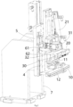
- Figure 1 shows an illustrative perspective view of a connector rotating device according to an exemplary embodiment of the present invention when viewed from one side
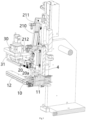
- Figure 2 shows an illustrative perspective view of a connector rotating device according to an exemplary embodiment of the present invention when viewed from the other side
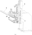
- Figure 3 shows a vertical sectional view of a connector rotating device according to an exemplary embodiment of the present invention
- Figure 4 shows an illustrative perspective view of a connector rotation device according to an exemplary embodiment of the present invention, wherein the first rotating module 1 is moved to a working position
- Figure 5 shows an illustrative perspective view of a connector rotation device according to an exemplary embodiment of the present invention, wherein the second rotating module 2 and the third rotating module 3 are moved to the working position.
- a connector rotating device in an exemplary embodiment of the present invention, includes: a first rotating module 1, a second rotating module 2, and a third rotating module 3.
- the first rotating module 1 is used to rotate a first connector (not shown) from a first initial orientation to a first predetermined orientation different from the first initial orientation.
- the second rotating module 2 is used to rotate a second connector (not shown) from a second initial orientation to a second predetermined orientation different from the second initial orientation.
- the third rotating module 3 is used to rotate the second connector from the second predetermined orientation to a third predetermined orientation different from the second predetermined orientation.
- the second rotating module 2 and the third rotating module 3 are arranged side by side in the first horizontal direction Y to enable the second connector to be rotated in sequence.
- the first rotating module 1 is spaced by a predetermined distance in the vertical direction Z from the second rotating module 2 and the third rotating module 3 to ensure that the first rotating module 1 does not interfere with the second rotating module 2 and the third rotating module 3 during rotation.
- the first rotating module 1 rotates the first connector around a first axis, and the first axis extends along a second horizontal direction X perpendicular to the first horizontal direction Y
- the second rotating module 2 rotates the second connector around a second axis, and the second axis extends along the first horizontal direction Y
- the third rotating module 3 rotates the second connector around a third axis, and the third axis extends in the vertical direction Z.
- the first rotating module 1 when the first rotating module 1 rotates the first connector from the first initial orientation to the first predetermined orientation, the first rotating module 1 rotates 180 degrees around the first axis.
- the second rotating module 2 rotates the second connector from the second initial orientation to the second predetermined orientation
- the second rotating module 2 rotates 90 degrees around the second axis.
- the third rotating module 3 rotates the second connector from the second predetermined orientation to the third predetermined orientation
- the third rotating module 3 rotates 180 degrees around the third axis.
- the shape and size of the first connector and the second connector are identical, the direction of the cable socket in the first connector is different from that of the cable socket in the second connector.
- the axial direction of the cable socket in the first connector is parallel to the longitudinal direction of the first connector, and the axial direction of the cable socket in the second connector is perpendicular to the longitudinal direction of the second connector.
- the first rotating module 1 is used to rotate the cable socket in the first connector to a predetermined orientation, in order to insert the cable into the cable socket in the first connector.
- the second rotating module 2 and the third rotating module 3 are used to rotate the cable socket in the second connector to a predetermined orientation, in order to insert the cable into the cable socket in the second connector.
- the connector rotating device further comprises a movable plate 4, which can be moved between a first position and a second position in the vertical direction Z.
- the first rotating module 1, the second rotating module 2, and the third rotating module 3 are installed on the movable plate 4 to move together with the movable plate 4.
- the transmission channel 9 transport the first or second connector to the next processing station, such as the cable insertion station and the terminal crimping station.
- the connector rotating device further comprises a fixed plate 5, a slide rail 61, and a slider 62.
- the slide rail 61 is fixed to the fixed plate 5 and extends in the vertical direction Z.
- the slider 62 slidably mounted onto the slide rail 61 to move along it.
- the movable plate 4 is connected to the slider 62 to be able to move along the vertical direction Z with the slider 62.
- the connector rotating device further comprises a driver 8, which is installed on the fixed plate 5 for driving the movable plate 4 to move between the first and second positions.
- the driver 8 may be an electric cylinder, a pneumatic cylinder, or a hydraulic cylinder.
- the connector rotating device further comprises a frame 7, and the fixed plate 5 is fixed to the frame 7.
- the first rotating module 1 comprises: a first carrier 10 and a first driver 11.
- the first carrier 10 is used to load the first connector.
- the first driver 11 is installed on the movable plate 4.
- the first carrier 10 has a first loading channel 101 for loading the first connector, and the first driver 11 is connected to the first carrier 10 for driving the first carrier 10 to rotate around the first axis.
- the first rotating module 1 further includes a connection channel 12, which is fixed to the movable plate 4.
- the first loading channel 101 of the first carrier 10 is docked with the connection channel 12 to allow the first connector to be transported from the first loading channel 101 to the connection channel 12.
- the connection channel 12 is docked with the transmission channel 9 to allow the first connector to be transported from the connection channel 12 to the transmission channel 9.
- the first driver 11 can be a motor, and the first carrier 10 is connected to the output shaft of the motor.
- the second rotating module 2 comprises: a second carrier 20 and a second driver 21.
- the second carrier 20 is used to load the second connector.
- the second driver 21 is installed on the movable plate 4.
- the second carrier 20 has a second loading channel 201 for loading the second connector, and the second driver 21 is connected to the second carrier 20 for driving the second carrier 20 to rotate around the second axis.
- the second rotating module 2 further includes an installation bracket 22, which is fixed to the movable plate 4.
- the second carrier 20 has a pivot shaft 20a, which is rotatably installed on the installation bracket 22, allowing the second carrier 20 to rotate around the second axis.
- the second driver 21 is a cylinder, and one end 211 of the cylinder block 210 of the cylinder is rotationally connected to the movable plate 4.
- the telescopic rod 212 of the cylinder extends out of the other end of the cylinder block 210 and is rotationally connected to the second carrier 20.
- the third rotating module 3 comprises a third carrier 30 and a third driver 31.
- the third carrier 30 is used to load the second connector.
- the third driver 31 is installed on the movable plate 4.
- the third carrier 30 has a third loading channel 301 for loading the second connector, and the third driver 31 is connected to the third carrier 30 for driving the third carrier 30 to rotate around the third axis.
- the third rotating module 3 further includes an installation plate 32, which is fixed to the movable plate 4.
- the third driver 31 is a motor and is installed on the installation plate 32, and the output shaft of the motor is connected to the third carrier 30.
- the second loading channel 201 on the second carrier 20 is docked with the third loading channel 301 on the third carrier 30 to allow the second connector to be transported from the second loading channel 201 to the third loading channel 301.
- the third loading channel 301 is docked with the transmission channel 9 to allow the second connector to be transported from the third loading channel 301 to the transmission channel 9.
Landscapes
- Engineering & Computer Science (AREA)
- Manufacturing & Machinery (AREA)
- Details Of Connecting Devices For Male And Female Coupling (AREA)
- Manufacturing Of Electrical Connectors (AREA)
- Snaps, Bayonet Connections, Set Pins, And Snap Rings (AREA)
Abstract
The present invention discloses a connector rotating device. The connector rotating device comprises of: a first rotating module (1) which is used to rotate a first connector from a first initial orientation to a first predetermined orientation different from the first initial orientation; a second rotating module (2) which is used to rotate a second connector from a second initial orientation to a second predetermined orientation different from the second initial orientation; and a third rotating module (3) is used to rotate the second connector from the second predetermined orientation to a third predetermined orientation different from the second predetermined orientation. The second rotating module (2) and the third rotating module (3) are arranged side by side in a first horizontal direction (Y), and the first rotating module (1) is spaced by a predetermined distance from the second rotating module (2) and the third rotating module (3) in a vertical direction (Z). The connector rotation device of the present invention can perform rotation operations of different connectors, greatly expanding the applicability of the connector rotation device.
Description
- This application claims the benefit of Chinese Patent Application No.
CN202311049959.X filed on August 18, 2023 - The present invention relates to a connector rotating device.
- In the manufacturing process of connectors, it is necessary to rotate the connector to the predetermined orientation in order to insert the cable into the socket on the connector. In the prior art, the connector rotation device can only perform one type of connector rotation operation. Therefore, the existing connector rotation device cannot be applied to the rotation operation of different connectors. This severely limits the applicability of the connector rotating device.
- The present invention has been made to overcome or alleviate at least one aspect of the above mentioned disadvantages.
- According to an aspect of the present invention, there is provided a connector rotating device. The connector rotating device comprises of: a first rotating module which is used to rotate a first connector from a first initial orientation to a first predetermined orientation different from the first initial orientation; a second rotating module which is used to rotate a second connector from a second initial orientation to a second predetermined orientation different from the second initial orientation; and a third rotating module is used to rotate the second connector from the second predetermined orientation to a third predetermined orientation different from the second predetermined orientation. The second rotating module and the third rotating module are arranged side by side in a first horizontal direction, and the first rotating module is spaced by a predetermined distance from the second rotating module and the third rotating module in a vertical direction.
- According to an exemplary embodiment of the present invention, the first rotating module rotates the first connector around a first axis, and the first axis extends along a second horizontal direction perpendicular to the first horizontal direction; the second rotating module rotates the second connector around a second axis extending along the first horizontal direction, the third rotating module rotates the second connector around a third axis extending along the vertical direction.
- According to another exemplary embodiment of the present invention, when the first rotating module rotates the first connector from the first initial orientation to the first predetermined orientation, the first rotating module rotates 180 degrees around the first axis; when the second rotating module rotates the second connector from the second initial orientation to the second predetermined orientation, the second rotating module rotates 90 degrees around the second axis; when the third rotating module rotates the second connector from the second predetermined orientation to the third predetermined orientation, the third rotating module rotates 180 degrees around the third axis.
- According to another exemplary embodiment of the present invention, the connector rotating device further comprises a movable plate which can be moved between a first position and a second position in the vertical direction, wherein the first rotating module, the second rotating module, and the third rotating module are installed on the movable plate to move together with the movable plate. When the movable plate is moved to the first position, the first rotating module is moved to a working position docked with a transmission channel, the second rotating module and the third rotating module are moved to a non-working position separated from the transmission channel; when the movable plate is moved to the second position, the first rotating module is moved to a non-working position separate from the transmission channel, the second rotating module and the third rotating module are moved to the working position docked with the transmission channel.
- According to another exemplary embodiment of the present invention, the connector rotating device further comprises of: a fixed plate; a slide rail which is fixed to the fixed plate and extends in the vertical direction; and a slider which is slidably installed on the slide rail to be able to move along the slide rail. The movable plate is connected to the slider to be able to move along the vertical direction with the slider.
- According to another exemplary embodiment of the present invention, the connector rotating device further comprises a driver which is installed on the fixed plate to drive the movable plate to move between the first position and the second position.
- According to another exemplary embodiment of the present invention, the driver is an electric cylinder, a pneumatic cylinder, or a hydraulic cylinder.
- According to another exemplary embodiment of the present invention, the connector rotating device further comprises a frame on which the fixed plate is fixed.
- According to another exemplary embodiment of the present invention, the first rotating module comprises: a first carrier for loading the first connector; and a first driver installed on the movable plate. The first carrier has a first loading channel for loading the first connector, and the first driver is connected to the first carrier for driving the first carrier to rotate around the first axis.
- According to another exemplary embodiment of the present invention, the first rotating module further comprises a connection channel fixed to the movable plate. When the first carrier rotates the first connector from the first initial orientation to the first predetermined orientation, the first loading channel of the first carrier is docked with the connection channel to allow the first connector to be transported from the first loading channel to the connection channel; when the first rotating module is moved to the working position, the connection channel is docked with the transmission channel to allow the first connector to be transported from the connection channel to the transmission channel.
- According to another exemplary embodiment of the present invention, the first driver is a motor, and the first carrier is connected to an output shaft of the motor.
- According to another exemplary embodiment of the present invention, the second rotating module comprises: a second carrier for loading the second connector; and a second driver installed on the movable plate. The second carrier has a second loading channel for loading the second connector, and the second driver is connected to the second carrier for driving the second carrier to rotate around the second axis.
- According to another exemplary embodiment of the present invention, the second rotating module further comprises an installation bracket fixed to the movable plate, the second carrier has a pivot shaft which is rotatably mounted on the installation bracket to enable the second carrier to rotate around the second axis.
- According to another exemplary embodiment of the present invention, the second driver is a cylinder, and one end of the cylinder body of the cylinder is rotatably connected to the movable plate, the telescopic rod of the cylinder extends out of the other end of the cylinder body and is rotatably connected to the second carrier.
- According to another exemplary embodiment of the present invention, the third rotating module comprises: a third carrier for loading the second connector; and a third driver installed on the movable plate. The third carrier has a third loading channel for loading the second connector, and the third driver is connected to the third carrier for driving the third carrier to rotate around the third axis.
- According to another exemplary embodiment of the present invention, the third rotating module further comprises an installation plate fixed to the movable plate, the third driver is a motor and is installed on the installation plate, and the output shaft of the motor is connected to the third carrier.
- According to another exemplary embodiment of the present invention, when the second carrier rotates the second connector from the second initial orientation to the second predetermined orientation, the second loading channel on the second carrier is docked with the third loading channel of the third carrier to allow the second connector to be transported from the second loading channel to the third loading channel.
- According to another exemplary embodiment of the present invention, when the second rotating module and the third rotating module are moved to the working position and the third rotating module rotates the second connector to the third predetermined orientation, the third loading channel is docked with the transmission channel to allow the second connector to be transported from the third loading channel to the transmission channel.
- In the aforementioned exemplary embodiments of the present invention, the connector rotation device can perform rotation operations of different connectors, greatly expanding the scope of application of the connector rotation device.
- The above and other features of the present invention will become more apparent by describing in detail exemplary embodiments thereof with reference to the accompanying drawings, in which:
-
Figure 1 shows an illustrative perspective view of a connector rotating device according to an exemplary embodiment of the present invention when viewed from one side; -
Figure 2 shows an illustrative perspective view of a connector rotating device according to an exemplary embodiment of the present invention when viewed from the other side; -
Figure 3 shows a vertical sectional view of a connector rotating device according to an exemplary embodiment of the present invention; -
Figure 4 shows an illustrative perspective view of a connector rotating device according to an exemplary embodiment of the present invention, wherein the first rotating module is moved to a working position; and -
Figure 5 shows an illustrative perspective view of a connector rotation device according to an exemplary embodiment of the present invention, wherein the second and third rotating modules are moved to the working position. - Exemplary embodiments of the present disclosure will be described hereinafter in detail with reference to the attached drawings, wherein the like reference numerals refer to the like elements. The present disclosure may, however, be embodied in many different forms and should not be construed as being limited to the embodiment set forth herein; rather, these embodiments are provided so that the present disclosure will be thorough and complete, and will fully convey the concept of the disclosure to those skilled in the art.
- In the following detailed description, for purposes of explanation, numerous specific details are set forth in order to provide a thorough understanding of the disclosed embodiments. It will be apparent, however, that one or more embodiments may be practiced without these specific details. In other instances, well-known structures and devices are schematically shown in order to simplify the drawing.
- According to a general concept of the present invention, there is provided a connector rotating device. The connector rotating device comprises of: a first rotating module which is used to rotate a first connector from a first initial orientation to a first predetermined orientation different from the first initial orientation; a second rotating module which is used to rotate a second connector from a second initial orientation to a second predetermined orientation different from the second initial orientation; and a third rotating module is used to rotate the second connector from the second predetermined orientation to a third predetermined orientation different from the second predetermined orientation. The second rotating module and the third rotating module are arranged side by side in a first horizontal direction, and the first rotating module is spaced by a predetermined distance from the second rotating module and the third rotating module in a vertical direction.
-
Figure 1 shows an illustrative perspective view of a connector rotating device according to an exemplary embodiment of the present invention when viewed from one side;Figure 2 shows an illustrative perspective view of a connector rotating device according to an exemplary embodiment of the present invention when viewed from the other side;Figure 3 shows a vertical sectional view of a connector rotating device according to an exemplary embodiment of the present invention;Figure 4 shows an illustrative perspective view of a connector rotation device according to an exemplary embodiment of the present invention, wherein the first rotatingmodule 1 is moved to a working position;Figure 5 shows an illustrative perspective view of a connector rotation device according to an exemplary embodiment of the present invention, wherein the second rotatingmodule 2 and the third rotating module 3 are moved to the working position. - As shown in
Figures 1 to 5 , in an exemplary embodiment of the present invention, a connector rotating device is disclosed. The connector rotating device includes: afirst rotating module 1, asecond rotating module 2, and a third rotating module 3. Thefirst rotating module 1 is used to rotate a first connector (not shown) from a first initial orientation to a first predetermined orientation different from the first initial orientation. The second rotatingmodule 2 is used to rotate a second connector (not shown) from a second initial orientation to a second predetermined orientation different from the second initial orientation. The third rotating module 3 is used to rotate the second connector from the second predetermined orientation to a third predetermined orientation different from the second predetermined orientation. - As shown in
Figures 1 to 5 , in the illustrated embodiments, thesecond rotating module 2 and the third rotating module 3 are arranged side by side in the first horizontal direction Y to enable the second connector to be rotated in sequence. Thefirst rotating module 1 is spaced by a predetermined distance in the vertical direction Z from thesecond rotating module 2 and the third rotating module 3 to ensure that thefirst rotating module 1 does not interfere with thesecond rotating module 2 and the third rotating module 3 during rotation. - As shown in
Figures 1 to 5 , in the illustrated embodiment, thefirst rotating module 1 rotates the first connector around a first axis, and the first axis extends along a second horizontal direction X perpendicular to the first horizontal direction Y Thesecond rotating module 2 rotates the second connector around a second axis, and the second axis extends along the first horizontal direction Y The third rotating module 3 rotates the second connector around a third axis, and the third axis extends in the vertical direction Z. - As shown in
Figures 1 to 5 , in the illustrated embodiments, when thefirst rotating module 1 rotates the first connector from the first initial orientation to the first predetermined orientation, the first rotatingmodule 1 rotates 180 degrees around the first axis. When the secondrotating module 2 rotates the second connector from the second initial orientation to the second predetermined orientation, the secondrotating module 2 rotates 90 degrees around the second axis. When the third rotating module 3 rotates the second connector from the second predetermined orientation to the third predetermined orientation, the third rotating module 3 rotates 180 degrees around the third axis. - Although not illustrated, in an exemplary embodiment of the present invention, the shape and size of the first connector and the second connector are identical, the direction of the cable socket in the first connector is different from that of the cable socket in the second connector. For example, the axial direction of the cable socket in the first connector is parallel to the longitudinal direction of the first connector, and the axial direction of the cable socket in the second connector is perpendicular to the longitudinal direction of the second connector. The first
rotating module 1 is used to rotate the cable socket in the first connector to a predetermined orientation, in order to insert the cable into the cable socket in the first connector. The secondrotating module 2 and the third rotating module 3 are used to rotate the cable socket in the second connector to a predetermined orientation, in order to insert the cable into the cable socket in the second connector. - As shown in
Figures 1 to 5 , in the illustrated embodiments, the connector rotating device further comprises amovable plate 4, which can be moved between a first position and a second position in the vertical direction Z. The firstrotating module 1, the secondrotating module 2, and the third rotating module 3 are installed on themovable plate 4 to move together with themovable plate 4. - As shown in
Figures 1 to 5 , in the illustrated embodiments, when themovable plate 4 is moved to the first position (as shown inFigure 4 ), the firstrotating module 1 is moved to the working position docked with thetransmission channel 9, the secondrotating module 2 and the third rotating module 3 are moved to a non-working position separated from thetransmission channel 9. - As shown in
Figures 1 to 5 , in the illustrated embodiments, when themovable plate 4 is moved to a second position (as shown inFigure 5 ), the firstrotating module 1 is moved to the non-working position separate from thetransmission channel 9, and the secondrotating module 2 and the third rotating module 3 are moved to the working position docked with thetransmission channel 9. - As shown in
Figures 1 to 5 , in the illustrated embodiments, after the first or second connector is rotated, thetransmission channel 9 transport the first or second connector to the next processing station, such as the cable insertion station and the terminal crimping station. - As shown in
Figures 1 to 5 , in the illustrated embodiments, the connector rotating device further comprises a fixedplate 5, aslide rail 61, and aslider 62. Theslide rail 61 is fixed to the fixedplate 5 and extends in the vertical direction Z. Theslider 62 slidably mounted onto theslide rail 61 to move along it. Themovable plate 4 is connected to theslider 62 to be able to move along the vertical direction Z with theslider 62. - As shown in
Figures 1 to 5 , in the illustrated embodiments, the connector rotating device further comprises adriver 8, which is installed on the fixedplate 5 for driving themovable plate 4 to move between the first and second positions. In an exemplary embodiment of the present invention, thedriver 8 may be an electric cylinder, a pneumatic cylinder, or a hydraulic cylinder. - As shown in
Figures 1 to 5 , in the illustrated embodiments, the connector rotating device further comprises aframe 7, and the fixedplate 5 is fixed to theframe 7. - As shown in
Figures 1 to 5 , in the illustrated embodiment, the firstrotating module 1 comprises: afirst carrier 10 and afirst driver 11. Thefirst carrier 10 is used to load the first connector. Thefirst driver 11 is installed on themovable plate 4. Thefirst carrier 10 has afirst loading channel 101 for loading the first connector, and thefirst driver 11 is connected to thefirst carrier 10 for driving thefirst carrier 10 to rotate around the first axis. - As shown in
Figures 1 to 5 , in the illustrated embodiment, the firstrotating module 1 further includes aconnection channel 12, which is fixed to themovable plate 4. When thefirst carrier 10 rotates the first connector from the first initial orientation to the first predetermined orientation, thefirst loading channel 101 of thefirst carrier 10 is docked with theconnection channel 12 to allow the first connector to be transported from thefirst loading channel 101 to theconnection channel 12. When the firstrotating module 1 is moved to the working position, theconnection channel 12 is docked with thetransmission channel 9 to allow the first connector to be transported from theconnection channel 12 to thetransmission channel 9. - As shown in
Figures 1 to 5 , in the illustrated embodiments, thefirst driver 11 can be a motor, and thefirst carrier 10 is connected to the output shaft of the motor. - As shown in
Figures 1 to 5 , in the illustrated embodiment, the secondrotating module 2 comprises: asecond carrier 20 and asecond driver 21. Thesecond carrier 20 is used to load the second connector. Thesecond driver 21 is installed on themovable plate 4. Thesecond carrier 20 has asecond loading channel 201 for loading the second connector, and thesecond driver 21 is connected to thesecond carrier 20 for driving thesecond carrier 20 to rotate around the second axis. - As shown in
Figures 1 to 5 , in the illustrated embodiment, the secondrotating module 2 further includes aninstallation bracket 22, which is fixed to themovable plate 4. Thesecond carrier 20 has apivot shaft 20a, which is rotatably installed on theinstallation bracket 22, allowing thesecond carrier 20 to rotate around the second axis. - As shown in
Figures 1 to 5 , in the illustrated embodiments, thesecond driver 21 is a cylinder, and oneend 211 of thecylinder block 210 of the cylinder is rotationally connected to themovable plate 4. Thetelescopic rod 212 of the cylinder extends out of the other end of thecylinder block 210 and is rotationally connected to thesecond carrier 20. - As shown in
Figures 1 to 5 , in the illustrated embodiment, the third rotating module 3 comprises athird carrier 30 and athird driver 31. Thethird carrier 30 is used to load the second connector. Thethird driver 31 is installed on themovable plate 4. Thethird carrier 30 has athird loading channel 301 for loading the second connector, and thethird driver 31 is connected to thethird carrier 30 for driving thethird carrier 30 to rotate around the third axis. - As shown in
Figures 1 to 5 , in the illustrated embodiment, the third rotating module 3 further includes aninstallation plate 32, which is fixed to themovable plate 4. Thethird driver 31 is a motor and is installed on theinstallation plate 32, and the output shaft of the motor is connected to thethird carrier 30. - As shown in
Figures 1 to 5 , in the illustrated embodiments, when thesecond carrier 20 rotates the second connector from the second initial orientation to the second predetermined orientation, thesecond loading channel 201 on thesecond carrier 20 is docked with thethird loading channel 301 on thethird carrier 30 to allow the second connector to be transported from thesecond loading channel 201 to thethird loading channel 301. - As shown in
Figures 1 to 5 , in the illustrated embodiments, when the secondrotating module 2 and the third rotating module 3 are moved to the working position and the third rotating module 3 rotates the second connector to the third predetermined orientation, thethird loading channel 301 is docked with thetransmission channel 9 to allow the second connector to be transported from thethird loading channel 301 to thetransmission channel 9. - It should be appreciated for those skilled in this art that the above embodiments are intended to be illustrated, and not restrictive. For example, many modifications may be made to the above embodiments by those skilled in this art, and various features described in different embodiments may be freely combined with each other without conflicting in configuration or principle.
- Although several exemplary embodiments have been shown and described, it would be appreciated by those skilled in the art that various changes or modifications may be made in these embodiments without departing from the principles and spirit of the disclosure, the scope of which is defined in the claims and their equivalents.
- As used herein, an element recited in the singular and proceeded with the word "a" or "an" should be understood as not excluding plural of said elements or steps, unless such exclusion is explicitly stated. Furthermore, references to "one embodiment" of the present invention are not intended to be interpreted as excluding the existence of additional embodiments that also incorporate the recited features. Moreover, unless explicitly stated to the contrary, embodiments "comprising" or "having" an element or a plurality of elements having a particular property may include additional such elements not having that property.
Claims (15)
- A connector rotating device, comprising:a first rotating module (1) which is used to rotate a first connector from a first initial orientation to a first predetermined orientation different from the first initial orientation;a second rotating module (2) which is used to rotate a second connector from a second initial orientation to a second predetermined orientation different from the second initial orientation; anda third rotating module (3) is used to rotate the second connector from the second predetermined orientation to a third predetermined orientation different from the second predetermined orientation,wherein the second rotating module (2) and the third rotating module (3) are arranged side by side in a first horizontal direction (Y), and the first rotating module (1) is spaced by a predetermined distance from the second rotating module (2) and the third rotating module (3) in a vertical direction (Z).
- The connector rotating device according to claim 1,wherein the first rotating module (1) rotates the first connector around a first axis, and the first axis extends along a second horizontal direction (X) perpendicular to the first horizontal direction (Y); andwherein the second rotating module (2) rotates the second connector around a second axis extending along the first horizontal direction (Y), the third rotating module (3) rotates the second connector around a third axis extending along the vertical direction (Z).
- The connector rotating device according to claim 2,wherein when the first rotating module (1) rotates the first connector from the first initial orientation to the first predetermined orientation, the first rotating module (1) rotates 180 degrees around the first axis;wherein when the second rotating module (2) rotates the second connector from the second initial orientation to the second predetermined orientation, the second rotating module (2) rotates 90 degrees around the second axis;wherein when the third rotating module (3) rotates the second connector from the second predetermined orientation to the third predetermined orientation, the third rotating module (3) rotates 180 degrees around the third axis.
- The connector rotating device according to claim 2 or 3, further comprising:a movable plate (4) which can be moved between a first position and a second position in the vertical direction (Z), wherein the first rotating module (1), the second rotating module (2), and the third rotating module (3) are installed on the movable plate (4) to move together with the movable plate (4),wherein when the movable plate (4) is moved to the first position, the first rotating module (1) is moved to a working position docked with a transmission channel (9), the second rotating module (2) and the third rotating module (3) are moved to a non-working position separated from the transmission channel (9),wherein when the movable plate (4) is moved to the second position, the first rotating module (1) is moved to a non-working position separate from the transmission channel (9), the second rotating module (2) and the third rotating module (3) are moved to the working position docked with the transmission channel (9).
- The connector rotating device according to claim 4, further comprising:a fixed plate (5);a slide rail (61) which is fixed to the fixed plate (5) and extends in the vertical direction (Z); anda slider (62) which is slidably installed on the slide rail (61) to be able to move along the slide rail (61),wherein the movable plate (4) is connected to the slider (62) to be able to move along the vertical direction (Z) with the slider (62).
- The connector rotating device according to claim 5, further comprising:
a driver (8) which is installed on the fixed plate (5) to drive the movable plate (4) to move between the first position and the second position. - The connector rotating device according to claim 6, further comprising:
a frame (7) on which the fixed plate (5) is fixed. - The connector rotating device according to claim 4,wherein the first rotating module (1) comprises:a first carrier (10) for loading the first connector; anda first driver (11) installed on the movable plate (4),wherein the first carrier (10) has a first loading channel (101) for loading the first connector, and the first driver (11) is connected to the first carrier (10) for driving the first carrier (10) to rotate around the first axis.
- The connector rotating device according to claim 8,wherein the first rotating module (1) further comprises:
a connection channel (12) fixed to the movable plate (4),wherein when the first carrier (10) rotates the first connector from the first initial orientation to the first predetermined orientation, the first loading channel (101) of the first carrier (10) is docked with the connection channel (12) to allow the first connector to be transported from the first loading channel (101) to the connection channel (12),wherein when the first rotating module (1) is moved to the working position, the connection channel (12) is docked with the transmission channel (9) to allow the first connector to be transported from the connection channel (12) to the transmission channel (9). - The connector rotating device according to claim 4,wherein the second rotating module (2) comprises:a second carrier (20) for loading the second connector; anda second driver (21) installed on the movable plate (4),wherein the second carrier (20) has a second loading channel (201) for loading the second connector, and the second driver (21) is connected to the second carrier (20) for driving the second carrier (20) to rotate around the second axis.
- The connector rotating device according to claim 10,wherein the second rotating module (2) further comprises:
an installation bracket (22) fixed to the movable plate (4),wherein the second carrier (20) has a pivot shaft (20a) which is rotatably mounted on the installation bracket (22) to enable the second carrier (20) to rotate around the second axis,wherein the second driver (21) is a cylinder, and one end (211) of the cylinder body (210) of the cylinder is rotatably connected to the movable plate (4), the telescopic rod (212) of the cylinder extends out of the other end of the cylinder body (210) and is rotatably connected to the second carrier (20). - The connector rotating device according to claim 10,wherein the third rotating module (3) comprises:a third carrier (30) for loading the second connector; anda third driver (31) installed on the movable plate (4),wherein the third carrier (30) has a third loading channel (301) for loading the second connector, and the third driver (31) is connected to the third carrier (30) for driving the third carrier (30) to rotate around the third axis.
- The connector rotating device according to claim 12,
wherein the third rotating module (3) further comprises:an installation plate (32) fixed to the movable plate (4),wherein the third driver (31) is a motor and is installed on the installation plate (32), and the output shaft of the motor is connected to the third carrier (30). - The connector rotating device according to claim 13,
wherein when the second carrier (20) rotates the second connector from the second initial orientation to the second predetermined orientation, the second loading channel (201) on the second carrier (20) is docked with the third loading channel (301) of the third carrier (30) to allow the second connector to be transported from the second loading channel (201) to the third loading channel (301). - The connector rotating device according to claim 14,
wherein when the second rotating module (2) and the third rotating module (3) are moved to the working position and the third rotating module (3) rotates the second connector to the third predetermined orientation, the third loading channel (301) is docked with the transmission channel (9) to allow the second connector to be transported from the third loading channel (301) to the transmission channel (9).
Applications Claiming Priority (1)
| Application Number | Priority Date | Filing Date | Title |
|---|---|---|---|
| CN202311049959.XA CN119496016A (en) | 2023-08-18 | 2023-08-18 | Connector Rotation Equipment |
Publications (1)
| Publication Number | Publication Date |
|---|---|
| EP4510394A1 true EP4510394A1 (en) | 2025-02-19 |
Family
ID=92303057
Family Applications (1)
| Application Number | Title | Priority Date | Filing Date |
|---|---|---|---|
| EP24194256.4A Pending EP4510394A1 (en) | 2023-08-18 | 2024-08-13 | Connector rotating device |
Country Status (5)
| Country | Link |
|---|---|
| US (1) | US20250062580A1 (en) |
| EP (1) | EP4510394A1 (en) |
| JP (1) | JP2025028774A (en) |
| CN (1) | CN119496016A (en) |
| TW (1) | TW202510442A (en) |
Citations (1)
| Publication number | Priority date | Publication date | Assignee | Title |
|---|---|---|---|---|
| CN115842278A (en) * | 2023-02-15 | 2023-03-24 | 广州知崇新能源科技有限公司 | Automatic loading attachment and terminal press-connection machine |
-
2023
- 2023-08-18 CN CN202311049959.XA patent/CN119496016A/en active Pending
-
2024
- 2024-08-13 EP EP24194256.4A patent/EP4510394A1/en active Pending
- 2024-08-14 JP JP2024135226A patent/JP2025028774A/en active Pending
- 2024-08-15 TW TW113130682A patent/TW202510442A/en unknown
- 2024-08-16 US US18/807,287 patent/US20250062580A1/en active Pending
Patent Citations (1)
| Publication number | Priority date | Publication date | Assignee | Title |
|---|---|---|---|---|
| CN115842278A (en) * | 2023-02-15 | 2023-03-24 | 广州知崇新能源科技有限公司 | Automatic loading attachment and terminal press-connection machine |
Also Published As
| Publication number | Publication date |
|---|---|
| CN119496016A (en) | 2025-02-21 |
| JP2025028774A (en) | 2025-03-03 |
| TW202510442A (en) | 2025-03-01 |
| US20250062580A1 (en) | 2025-02-20 |
Similar Documents
| Publication | Publication Date | Title |
|---|---|---|
| EP0159006B1 (en) | Method of and apparatus for fitting rubber stopper | |
| CN209830791U (en) | Switch terminal material loading assembly device | |
| EP3763557B1 (en) | Automated connection of a charging connector to a charging interface of a vehicle | |
| US6961996B2 (en) | Method for installing cable ends in plug housings | |
| EP3477797A1 (en) | Assembly system and assembly method | |
| EP1608044B1 (en) | A construction and a method for connecting an intermediate connector and one or more electrical components | |
| US20250062580A1 (en) | Connector Rotating Device | |
| US8337137B2 (en) | Transfer module for transferring parts between work stations | |
| US12472551B2 (en) | Cable bending system | |
| CN108074679B (en) | Rotary wire transfer for automated wire processing systems and methods | |
| CN108736288B (en) | Terminating machine for terminating a wire harness of a motor stator to a terminal set | |
| EP0881720B1 (en) | Apparatus for assembling grommet to lead | |
| US5519937A (en) | Guiding method and device for the automatic introduction of a male piece into a female piece | |
| EP3928386B1 (en) | Automated hybrid installation for the wiring of connectors | |
| JP2011152558A (en) | Guide cam mechanism for preventing interference | |
| CN220652551U (en) | Connector rotating device | |
| US20240120696A1 (en) | Wire Processing Device | |
| CN217642100U (en) | Automatic terminal assembling equipment | |
| EP4238192B1 (en) | Device and method for assembling a plug connector | |
| CN1921030A (en) | Tooling apparatus for a rigid harness of large cross section | |
| CN217767967U (en) | Wire twisting mechanism | |
| EP4629457A1 (en) | Twisted pair cable processing system, twisted pair cable cutting method and untwisting method | |
| US6392185B1 (en) | Electrical welding clamp comprising a mechanical device for indexing and de-indexing | |
| CN111762080B (en) | Retractable clamping device and its AGV | |
| CN210754829U (en) | Flat wire metal material turns over a equipment |
Legal Events
| Date | Code | Title | Description |
|---|---|---|---|
| PUAI | Public reference made under article 153(3) epc to a published international application that has entered the european phase |
Free format text: ORIGINAL CODE: 0009012 |
|
| STAA | Information on the status of an ep patent application or granted ep patent |
Free format text: STATUS: THE APPLICATION HAS BEEN PUBLISHED |
|
| AK | Designated contracting states |
Kind code of ref document: A1 Designated state(s): AL AT BE BG CH CY CZ DE DK EE ES FI FR GB GR HR HU IE IS IT LI LT LU LV MC ME MK MT NL NO PL PT RO RS SE SI SK SM TR |
|
| STAA | Information on the status of an ep patent application or granted ep patent |
Free format text: STATUS: REQUEST FOR EXAMINATION WAS MADE |
|
| 17P | Request for examination filed |
Effective date: 20250818 |