EP4510307A1 - Battery pack and energy storage device - Google Patents
Battery pack and energy storage device Download PDFInfo
- Publication number
- EP4510307A1 EP4510307A1 EP24189921.0A EP24189921A EP4510307A1 EP 4510307 A1 EP4510307 A1 EP 4510307A1 EP 24189921 A EP24189921 A EP 24189921A EP 4510307 A1 EP4510307 A1 EP 4510307A1
- Authority
- EP
- European Patent Office
- Prior art keywords
- protection member
- battery pack
- connection valve
- accommodation cavity
- cooling plate
- Prior art date
- Legal status (The legal status is an assumption and is not a legal conclusion. Google has not performed a legal analysis and makes no representation as to the accuracy of the status listed.)
- Pending
Links
Images

Classifications
-
- H—ELECTRICITY
- H01—ELECTRIC ELEMENTS
- H01M—PROCESSES OR MEANS, e.g. BATTERIES, FOR THE DIRECT CONVERSION OF CHEMICAL ENERGY INTO ELECTRICAL ENERGY
- H01M50/00—Constructional details or processes of manufacture of the non-active parts of electrochemical cells other than fuel cells, e.g. hybrid cells
- H01M50/20—Mountings; Secondary casings or frames; Racks, modules or packs; Suspension devices; Shock absorbers; Transport or carrying devices; Holders
- H01M50/233—Mountings; Secondary casings or frames; Racks, modules or packs; Suspension devices; Shock absorbers; Transport or carrying devices; Holders characterised by physical properties of casings or racks, e.g. dimensions
- H01M50/242—Mountings; Secondary casings or frames; Racks, modules or packs; Suspension devices; Shock absorbers; Transport or carrying devices; Holders characterised by physical properties of casings or racks, e.g. dimensions adapted for protecting batteries against vibrations, collision impact or swelling
-
- H—ELECTRICITY
- H01—ELECTRIC ELEMENTS
- H01M—PROCESSES OR MEANS, e.g. BATTERIES, FOR THE DIRECT CONVERSION OF CHEMICAL ENERGY INTO ELECTRICAL ENERGY
- H01M10/00—Secondary cells; Manufacture thereof
- H01M10/60—Heating or cooling; Temperature control
- H01M10/61—Types of temperature control
- H01M10/613—Cooling or keeping cold
-
- H—ELECTRICITY
- H01—ELECTRIC ELEMENTS
- H01M—PROCESSES OR MEANS, e.g. BATTERIES, FOR THE DIRECT CONVERSION OF CHEMICAL ENERGY INTO ELECTRICAL ENERGY
- H01M10/00—Secondary cells; Manufacture thereof
- H01M10/60—Heating or cooling; Temperature control
- H01M10/65—Means for temperature control structurally associated with the cells
- H01M10/655—Solid structures for heat exchange or heat conduction
- H01M10/6556—Solid parts with flow channel passages or pipes for heat exchange
-
- H—ELECTRICITY
- H01—ELECTRIC ELEMENTS
- H01M—PROCESSES OR MEANS, e.g. BATTERIES, FOR THE DIRECT CONVERSION OF CHEMICAL ENERGY INTO ELECTRICAL ENERGY
- H01M10/00—Secondary cells; Manufacture thereof
- H01M10/60—Heating or cooling; Temperature control
- H01M10/65—Means for temperature control structurally associated with the cells
- H01M10/656—Means for temperature control structurally associated with the cells characterised by the type of heat-exchange fluid
- H01M10/6567—Liquids
-
- H—ELECTRICITY
- H01—ELECTRIC ELEMENTS
- H01M—PROCESSES OR MEANS, e.g. BATTERIES, FOR THE DIRECT CONVERSION OF CHEMICAL ENERGY INTO ELECTRICAL ENERGY
- H01M10/00—Secondary cells; Manufacture thereof
- H01M10/60—Heating or cooling; Temperature control
- H01M10/65—Means for temperature control structurally associated with the cells
- H01M10/656—Means for temperature control structurally associated with the cells characterised by the type of heat-exchange fluid
- H01M10/6567—Liquids
- H01M10/6568—Liquids characterised by flow circuits, e.g. loops, located externally to the cells or cell casings
-
- H—ELECTRICITY
- H01—ELECTRIC ELEMENTS
- H01M—PROCESSES OR MEANS, e.g. BATTERIES, FOR THE DIRECT CONVERSION OF CHEMICAL ENERGY INTO ELECTRICAL ENERGY
- H01M50/00—Constructional details or processes of manufacture of the non-active parts of electrochemical cells other than fuel cells, e.g. hybrid cells
- H01M50/20—Mountings; Secondary casings or frames; Racks, modules or packs; Suspension devices; Shock absorbers; Transport or carrying devices; Holders
- H01M50/244—Secondary casings; Racks; Suspension devices; Carrying devices; Holders characterised by their mounting method
-
- Y—GENERAL TAGGING OF NEW TECHNOLOGICAL DEVELOPMENTS; GENERAL TAGGING OF CROSS-SECTIONAL TECHNOLOGIES SPANNING OVER SEVERAL SECTIONS OF THE IPC; TECHNICAL SUBJECTS COVERED BY FORMER USPC CROSS-REFERENCE ART COLLECTIONS [XRACs] AND DIGESTS
- Y02—TECHNOLOGIES OR APPLICATIONS FOR MITIGATION OR ADAPTATION AGAINST CLIMATE CHANGE
- Y02E—REDUCTION OF GREENHOUSE GAS [GHG] EMISSIONS, RELATED TO ENERGY GENERATION, TRANSMISSION OR DISTRIBUTION
- Y02E60/00—Enabling technologies; Technologies with a potential or indirect contribution to GHG emissions mitigation
- Y02E60/10—Energy storage using batteries
Definitions
- the present disclosure relates to the technical field of energy storage, and in particular, to a battery pack and an energy storage device.
- the battery module in the battery pack is usually cooled using an air cooling method or a liquid cooling method.
- the liquid cooling method is to arrange a liquid cooling plate in the battery pack, and connect the liquid cooling plate to an external cooling cabinet using a connection valve, so as to achieve cooling of the battery module.
- an embodiment of the present disclosure discloses a battery pack.
- the battery pack comprises a box, a battery module, a liquid cooling plate, a connection valve, a liquid supply pipe and a protection structure.
- the box is provided with an accommodation cavity and a mounting hole. The mounting hole is communicated with the accommodation cavity.
- the battery module is provided in the accommodation cavity.
- the liquid cooling plate is provided in the accommodation cavity.
- the liquid cooling plate is configured for cooling the battery module.
- the connection valve is provided in the mounting hole. One end of the connection valve outside the accommodation cavity is configured for connecting to a cooling cabinet.
- the liquid supply pipe is communicated with the liquid cooling plate and one end of the connection valve facing the accommodation cavity.
- the protection structure is detachably provided in the box. The protection structure is located outside the accommodation cavity, and covers the connection valve.
- an embodiment of the present disclosure discloses an energy storage device.
- the energy storage device comprises the battery pack disclosed in the first aspect.
- Battery pack 100. Battery pack; 10. Box; 10a. Accommodation cavity; 10b. Mounting hole; 10c. Positioning groove; 11. Base; 11a. Bottom plate; 11b. Side plate; 12. Cover; 20. Battery module; 30. Liquid cooling plate; 40. Connection valve; 40a, Limiting portion; 50. Liquid supply pipe; 60. Protection structure; 61. First protection member; 61a. Open end; 61b. First clamping part; 62. Second protection member; 62a. Second clamping part; 62b. Handle part; 70. Connector; 80. Sealing member; 200. Energy storage device.
- orientations or positional relationships indicated by the terms “on”, “under”, “left”, “right”, “front”, “back”, “top”, “bottom”, “inner”, “outer”, “middle”, “vertical”, “horizontal”, “transverse”, “longitudinal”, etc. are based on the orientations or positional relationships shown in the drawings. These terms are mainly used to better describe the present disclosure and its embodiments and are not intended to limit the indicated apparatus, element or component to having a specific orientation, or to be constructed and operated in a specific orientation.
- the terms “mount”, “arrange”, “provide”, “connect”, and “link” are to be construed broadly. For example, they may be a fixed connection, a detachable connection, or an integral construction; they may be a mechanical connection or an electrical connection; they may be a direct connection, or indirect connection through an intermediate medium, or internal connectivity between two apparatuses, elements or components.
- mount may be a fixed connection, a detachable connection, or an integral construction
- they may be a mechanical connection or an electrical connection
- they may be a direct connection, or indirect connection through an intermediate medium, or internal connectivity between two apparatuses, elements or components.
- first means two or more.
- connection valve In order to connect the liquid cooling plate to the external cooling cabinet, the connection valve is partially located outside the box of the battery pack. During the production and transportation of the battery pack, the connection valve is easily cracked or even broken due to external forces, which leads to the abnormal use of the battery pack.
- the present disclosure discloses a battery pack and an energy storage device.
- the protection structure is used to protect the connection valve to prevent the connection valve from being cracked or even broken due to external force, thereby ensuring the normal use of the battery pack.
- the battery pack 100 comprises a box 10, a battery module 20, a liquid cooling plate 30, a connection valve 40, a liquid supply pipe 50 and a protection structure 60.
- the box 10 is provided with an accommodation cavity 10a and a mounting hole 10b.
- the mounting hole 10b is communicated with the accommodation cavity 10a.
- the battery module 20 is provided in the accommodation cavity 10a.
- the liquid cooling plate 30 is provided in the accommodation cavity 10a, and the liquid cooling plate 30 is used for cooling the battery module 20.
- the connection valve 40 is provided in the mounting hole 10b.
- One end of the connection valve 40 that is located outside the accommodation cavity 10a is used for connecting to a cooling cabinet.
- the liquid supply pipe 50 is communicated with the liquid cooling plate 30 and one end of the connection valve 40 facing the accommodation cavity 10a.
- the protection structure 60 is detachably provided in the box 10.
- the protection structure 60 is located outside the accommodation cavity 10a and covers the connection valve 40.
- connection valve 40 may be a stop valve or other types of valve bodies, which may be selected according to actual conditions, and is not specifically limited in this embodiment.
- the battery module 20 and the liquid cooling plate 30 are arranged in the accommodation cavity 10a of the box 10.
- the connection valve 40 is arranged in the mounting hole 10b of the box 10.
- the mounting hole 10b is used to communicate with the accommodation cavity 10a, so that the liquid supply pipe 50 can be connected to the liquid cooling plate 30 and the connection valve 40, and the connection valve 40 is connected to the cooling cabinet. Therefore, the liquid cooling plate 30 cools the battery module 20.
- the protection structure 60 is detachably disposed on the box 10 and is used to cover the connection valve 40 to protect the connection valve 40, for preventing the connection valve 40 from being cracked or even broken due to external force, thereby ensuring the normal use of the battery pack 100, especially protecting the connection valve 40 during production and transportation of the battery pack 100.
- the protection structure 60 can be detached from the box 10 to expose the connection valve 40, so that the end of the connection valve 40 located outside the accommodation cavity 10a may be connected to the cooling cabinet.
- the protection structure 60 comprises a first protection member 61 and a second protection member 62.
- the first protection member 61 is connected to the box 10 and is arranged around a periphery of the connection valve 40.
- the first protection member 61 is provided with an open end 61a corresponding to the connection valve 40.
- the second protection member 62 is detachably connected to the first protection member 61 and closes the open end 61a.
- the first protection member 61 protects the circumferential portion of the connection valve 40
- the second protection member 62 closes the open end 61a, thereby protecting the connection valve 40 from the orientation direction of the end of the connection valve 40 that is located outside the accommodation cavity 10a.
- the second protection member 62 can be detached from the first protection member 61.
- the end of the connection valve 40 that is located outside the accommodation cavity 10a can be connected to the cooling cabinet, and the first protection member 61 can continue to protect the circumferential portion of the connection valve 40.
- the outer peripheral surface of the second protection member 62 is detachably connected to the inner peripheral surface of the first protection member 61, and the second protection member 62 is located between the first protection member 61 and the connection valve 40, and covers the connection valve 40.
- the first protection member 61 can provide a connection position for the second protection member 62, so that the second protection member 62 is detachably connected to the box 10.
- the detachable connection structure is located between the inner peripheral surface of the first protection member 61 and the outer peripheral surface of the second protection member 62, so that the detachable connection structure can be hidden.
- the second protection member 62 covers the connection valve 40 ,thereby protecting the connection valve 40 in all directions.
- the first protection member 61 located on the outer peripheral side of the second protection member 62 can provide double protection. Additionally, after the second protection member 62 is detached from the box 10, the first protection member 61 can also protect the connection valve 40.
- the inner peripheral surface of the second protection member 62 is detachably connected to the outer peripheral surface of the first protection member 61, and the second protection member 62 covers the open end 61a.
- the first protection member 61 can provide a connection position for the second protection member 62, so that the second protection member 62 can be detachably connected to the box 10.
- the connection valve 40 is protected in all directions by the second protection member 62 and the first protection member 61.
- the length of the second protection member 62 may be set smaller than the first protection member 61, thereby saving material and reducing weight, and reducing the difficulty of assembly and disassembly operations of the second protection member 62. Additionally, after the second protection member 62 is detached from the box 10, the first protection member 61 can also protect the connection valve 40.
- the first protection member 61 is provided with a first clamping part 61b
- the second protection member 62 is provided with a second clamping part 62a
- the second clamping part 62a is detachably connected to the first clamping part 61b.
- the second clamping part 62a and the first clamping part 61b are detachably connected with each other, which can reduce the difficulty of assembling and disassembling the second protecting member 62 and the first protecting member 61.
- one of the first clamping part 61b and the second clamping part 62a is provided with a convex portion, and the other is provided with a concave portion.
- the second protecting member 62 can rotate relative to the first protecting member 61 so that the convex portion and the concave portion are engaged or separated. In this way, the second protection member 62 moves along the length direction to cooperate with the first protection member 61, so that the convex portion and the concave portion are at the same position in the length direction. At this time, the second protection member 62 can be rotated to engage the convex portion with the concave portion, therefore the second protection member 62 can be assembled with the first protection member 61.
- the second protection member 62 When the second protection member 62 is rotated to separate the convex portion from the concave portion, the second protection member 62 can be moved along the length direction to be detached from the first protection member 61, so that the connection valve 40 is exposed to facilitate the connection between the connection valve 40 and the cooling cabinet.
- a handle portion 62b is provided at an end of the second protection member 62 away from the box 10, and the handle portion 62b is used for the user to rotate the second protection member 62.
- the handle portion 62b is used to provide a force application site for the user, and the user can assemble and disassemble the second protection member 62 and the first protection member 61 by rotating the second protection member 62, and the operation difficulty is relatively low.
- the first protection member 61 is made of a flexible material
- the second protection member 62 is made of a hard material.
- the first protection member 61 may be made of a foam, which has a buffering effect and can buffer external forces and reduce impacts.
- the second protection member 62 may be made of a material with relatively high hardness such as metal or plastic, which can provide good protection for the connection valve 40.
- the battery pack 100 further comprises a connector 70, which is provided in the mounting hole 10b.
- One end of the connector 70 protrudes into the accommodation cavity 10a and is connected to the liquid supply pipe 50, and the other end of the connector 70 protrudes out of the mounting hole 10b and is connected to the connection valve 40.
- one end of the connector 70 is connected to the connection valve 40 and the other end is connected to the liquid supply pipe 50, so that the connection valve 40 and the liquid supply pipe 50 can be connected.
- a sealing member 80 is provided between the connection valve 40 and the liquid supply pipe 50, and the sealing member 80 is used to seal the connection between the connection valve 40 and the liquid supply pipe 50.
- the sealing member 80 is used to seal the connection between the connection valve 40 and the liquid supply pipe 50, which can prevent liquid leakage and prevent foreign matter from entering the connection valve 40 and the liquid supply pipe 50 through the connection and causing damage to the entire cooling system.
- a limiting portion 40a is provided on the peripheral side of the connection valve 40, and the limiting portion 40a abuts against the outer surface of the box 10 along the extending direction of the mounting hole 10b.
- the extending length of the connection valve 40 into the mounting hole 10b can be limited, thereby preventing the connection valve 40 from excessively extending into the mounting hole 10b to affect the installation of component(s) in the accommodation cavity 10a or interfering with component(s) in the accommodation cavity 10a to cause damage.
- the box 10 comprises a base 11 and a cover 12.
- the cover 12 covers and is connected to the base 11 to form the accommodation cavity 10a.
- the mounting hole 10b is provided in the base 11.
- the liquid cooling plate 30 is provided in the base 11.
- the battery module 20 is carried on the liquid cooling plate 30.
- the cover 12 can be detached from the base 11 to perform maintenance, replacement and other operations on the component(s) in the accommodation cavity 10a.
- the base 11 comprises a bottom plate 11a and a plurality of side plates 11b.
- the plurality of side plates 11b are provided on the bottom plate 11a and are connected end to end so as to form a positioning groove 10c with the bottom plate 11a.
- the liquid cooling plate 30 is provided in the positioning groove 10c.
- the battery module 20 is partially located in the positioning groove 10c for positioning.
- the cover 12 covers and is connected to the plurality of side plates 11b.
- the accommodation cavity 10a is formed between the cover 12 and the positioning groove 10c. In this way, the liquid cooling plate 30 can be accommodated by the positioning groove 10c, and the battery module 20 can be pre-positioned to facilitate the assembly of the battery module 20.
- the base plate 11a and the liquid cooling plate 30 are an integrally molded piece, or the base plate 11a and the liquid cooling plate 30 are two independent pieces connected to each other.
- the base plate 11a and the liquid cooling plate 30 are formed as one integrated piece, the overall thickness and weight of the battery pack 100 can be reduced.
- the base plate 11a and the liquid cooling plate 30 are two independent pieces connected to each other, they can be assembled or disassembled, especially when the liquid cooling plate 30 needs to be replaced, the replacement is less difficult.
- the bottom plate 11a and the liquid cooling plate 30 are integrally molded piece.
- reference signs 11a and 30 are the same component, that is, the bottom plate 11a and the liquid cooling plate 30.
- the first embodiment of the present disclosure provides a battery pack 100.
- the battery module 20 and the liquid cooling plate 30 are provided in the accommodation cavity 10a of the box 10, the mounting hole 10b of the box 10 is provided with the connection valve 40, and the mounting hole 10b is used to communicate with the accommodation cavity 10a, so that the liquid supply pipe 50 can connect the liquid cooling plate 30 and the connection valve 40, thereby connecting with the cooling cabinet using the connection valve 40, and thus the liquid cooling plate 30 can cool the battery module 20.
- the protection structure 60 is detachably disposed on the box 10 and is used to cover the connection valve 40 to protect the connection valve 40, preventing the connection valve 40 from being cracked or even broken due to external force, thereby ensuring the normal use of the battery pack 100, especially protecting the connection valve 40 during production and transportation of the battery pack 100.
- the protection structure 60 can be detached from the box 10 to expose the connection valve 40, so that the end of the connection valve 40 located outside the accommodation cavity 10a is connected to the cooling cabinet.
- FIG. 6 is a schematic structural view of an energy storage device 200 provided in the second embodiment of the present disclosure.
- the energy storage device 200 comprises the battery pack of the first embodiment.
- the energy storage device 200 may be a household energy storage cabinet or an energy storage box in the form of a small container, which is not specifically limited in this embodiment.
- the energy storage device 200 may comprise one or more battery packs 100.
- the number of battery packs 100 in the energy storage device 200 may be 1, 2, 3, 4, etc., which is not specifically limited in this embodiment.
- the energy storage device 200 comprises a plurality of battery packs 100
- the plurality of battery packs 100 may be connected in series or in parallel, which is not specifically limited in this embodiment.
- the second embodiment of the present disclosure provides an energy storage device 200 in which the battery pack 100 can protect the connection valve using a protection structure, to prevent the connection valve from being cracked or even broken due to external force, thereby ensuring the normal use of the battery pack.
- the battery pack and the energy storage device disclosed in the embodiments of the present disclosure have been introduced in detail above.
- the present disclosure illustrates the principles and implementations of the present disclosure by using examples.
- the description of the above embodiments is only used to help understand the battery pack and the energy storage device of the present disclosure and core ideas thereof.
- the contents of this specification should not be understood as limitations of the present disclosure.
Landscapes
- Chemical & Material Sciences (AREA)
- Chemical Kinetics & Catalysis (AREA)
- Electrochemistry (AREA)
- General Chemical & Material Sciences (AREA)
- Engineering & Computer Science (AREA)
- Manufacturing & Machinery (AREA)
- Battery Mounting, Suspending (AREA)
- Secondary Cells (AREA)
Abstract
Description
- The present disclosure relates to the technical field of energy storage, and in particular, to a battery pack and an energy storage device.
- In the related art, the battery module in the battery pack is usually cooled using an air cooling method or a liquid cooling method. The liquid cooling method is to arrange a liquid cooling plate in the battery pack, and connect the liquid cooling plate to an external cooling cabinet using a connection valve, so as to achieve cooling of the battery module.
- In a first aspect, an embodiment of the present disclosure discloses a battery pack. The battery pack comprises a box, a battery module, a liquid cooling plate, a connection valve, a liquid supply pipe and a protection structure. The box is provided with an accommodation cavity and a mounting hole. The mounting hole is communicated with the accommodation cavity. The battery module is provided in the accommodation cavity. The liquid cooling plate is provided in the accommodation cavity. The liquid cooling plate is configured for cooling the battery module. The connection valve is provided in the mounting hole. One end of the connection valve outside the accommodation cavity is configured for connecting to a cooling cabinet. The liquid supply pipe is communicated with the liquid cooling plate and one end of the connection valve facing the accommodation cavity. The protection structure is detachably provided in the box. The protection structure is located outside the accommodation cavity, and covers the connection valve.
- In a second aspect, an embodiment of the present disclosure discloses an energy storage device. The energy storage device comprises the battery pack disclosed in the first aspect.
- In order to more clearly illustrate the technical solutions in the embodiments of the present disclosure, the drawings required in the embodiments will be briefly introduced below. Obviously, the drawings in the following description are only some embodiments of the present disclosure. Those of ordinary skill in the art can also obtain other drawings based on these drawings without exerting creative efforts.
-
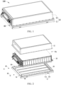
FIG. 1 is a schematic structural view of a battery pack disclosed in the first embodiment of the present disclosure; -
FIG. 2 is a schematic view of an exploded structure of the battery pack disclosed in the first embodiment of the present disclosure; -
FIG. 3 is a partial cross-sectional structural schematic view of the battery pack disclosed in the first embodiment of the present disclosure; -
FIG. 4 is a partial cross-sectional structural schematic view of another battery pack disclosed in the first embodiment of the present disclosure; -
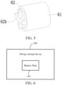
FIG. 5 is a schematic structural view of a protection structure disclosed in the first embodiment of the present disclosure; -
FIG. 6 is a schematic structural view of an energy storage device disclosed in the second embodiment of the present disclosure. - 100. Battery pack; 10. Box; 10a. Accommodation cavity; 10b. Mounting hole; 10c. Positioning groove; 11. Base; 11a. Bottom plate; 11b. Side plate; 12. Cover; 20. Battery module; 30. Liquid cooling plate; 40. Connection valve; 40a, Limiting portion; 50. Liquid supply pipe; 60. Protection structure; 61. First protection member; 61a. Open end; 61b. First clamping part; 62. Second protection member; 62a. Second clamping part; 62b. Handle part; 70. Connector; 80. Sealing member; 200. Energy storage device.
- The technical solutions in the embodiments of the present disclosure will be clearly and completely described below with reference to the accompanying drawings in the embodiments of the present disclosure. Obviously, the described embodiments are only some, not all, of the embodiments of the present disclosure. Based on the embodiments of the present disclosure, all other embodiments obtained by those of ordinary skill in the art without creative efforts fall within the scope of protection of the present disclosure.
- In the present disclosure, the orientations or positional relationships indicated by the terms "on", "under", "left", "right", "front", "back", "top", "bottom", "inner", "outer", "middle", "vertical", "horizontal", "transverse", "longitudinal", etc. are based on the orientations or positional relationships shown in the drawings. These terms are mainly used to better describe the present disclosure and its embodiments and are not intended to limit the indicated apparatus, element or component to having a specific orientation, or to be constructed and operated in a specific orientation.
- Moreover, some of the above terms may also be used to express other meanings in addition to indicating orientation or positional relationships. For example, the term "on" may also be used to express a certain dependence relationship or connection relationship in some cases. For those of ordinary skill in the art, the specific meanings of these terms in the present disclosure can be understood according to specific circumstances.
- In addition, the terms "mount", "arrange", "provide", "connect", and "link" are to be construed broadly. For example, they may be a fixed connection, a detachable connection, or an integral construction; they may be a mechanical connection or an electrical connection; they may be a direct connection, or indirect connection through an intermediate medium, or internal connectivity between two apparatuses, elements or components. For those of ordinary skill in the art, the specific meanings of the above terms in the present disclosure can be understood according to specific circumstances.
- In addition, the terms "first", "second", etc. are mainly used to distinguish different apparatuses, elements or components (the specific types and constructions may be the same or different), and are not used to indicate or imply the relative importance and number of the indicated apparatuses, elements or components. Unless otherwise stated, "a plurality of" means two or more.
- In order to connect the liquid cooling plate to the external cooling cabinet, the connection valve is partially located outside the box of the battery pack. During the production and transportation of the battery pack, the connection valve is easily cracked or even broken due to external forces, which leads to the abnormal use of the battery pack.
- The present disclosure discloses a battery pack and an energy storage device. The protection structure is used to protect the connection valve to prevent the connection valve from being cracked or even broken due to external force, thereby ensuring the normal use of the battery pack.
- Referring to
FIGs. 1 to 3 , which are schematic structural views of abattery pack 100 provided in the first embodiment of the present disclosure, thebattery pack 100 comprises abox 10, abattery module 20, aliquid cooling plate 30, aconnection valve 40, aliquid supply pipe 50 and aprotection structure 60. Thebox 10 is provided with anaccommodation cavity 10a and a mountinghole 10b. The mountinghole 10b is communicated with theaccommodation cavity 10a. Thebattery module 20 is provided in theaccommodation cavity 10a. Theliquid cooling plate 30 is provided in theaccommodation cavity 10a, and theliquid cooling plate 30 is used for cooling thebattery module 20. Theconnection valve 40 is provided in the mountinghole 10b. One end of theconnection valve 40 that is located outside theaccommodation cavity 10a is used for connecting to a cooling cabinet. Theliquid supply pipe 50 is communicated with theliquid cooling plate 30 and one end of theconnection valve 40 facing theaccommodation cavity 10a. Theprotection structure 60 is detachably provided in thebox 10. Theprotection structure 60 is located outside theaccommodation cavity 10a and covers theconnection valve 40. - The
connection valve 40 may be a stop valve or other types of valve bodies, which may be selected according to actual conditions, and is not specifically limited in this embodiment. - In this embodiment, the
battery module 20 and theliquid cooling plate 30 are arranged in theaccommodation cavity 10a of thebox 10. Theconnection valve 40 is arranged in the mountinghole 10b of thebox 10. The mountinghole 10b is used to communicate with theaccommodation cavity 10a, so that theliquid supply pipe 50 can be connected to theliquid cooling plate 30 and theconnection valve 40, and theconnection valve 40 is connected to the cooling cabinet. Therefore, theliquid cooling plate 30 cools thebattery module 20. At the same time, theprotection structure 60 is detachably disposed on thebox 10 and is used to cover theconnection valve 40 to protect theconnection valve 40, for preventing theconnection valve 40 from being cracked or even broken due to external force, thereby ensuring the normal use of thebattery pack 100, especially protecting theconnection valve 40 during production and transportation of thebattery pack 100. When theliquid cooling plate 30 needs to work, theprotection structure 60 can be detached from thebox 10 to expose theconnection valve 40, so that the end of theconnection valve 40 located outside theaccommodation cavity 10a may be connected to the cooling cabinet. - In some embodiments, the
protection structure 60 comprises afirst protection member 61 and asecond protection member 62. Thefirst protection member 61 is connected to thebox 10 and is arranged around a periphery of theconnection valve 40. Thefirst protection member 61 is provided with anopen end 61a corresponding to theconnection valve 40. Thesecond protection member 62 is detachably connected to thefirst protection member 61 and closes theopen end 61a. In this way, through the cooperation of thefirst protection member 61 and thesecond protection member 62, thefirst protection member 61 protects the circumferential portion of theconnection valve 40, and thesecond protection member 62 closes theopen end 61a, thereby protecting theconnection valve 40 from the orientation direction of the end of theconnection valve 40 that is located outside theaccommodation cavity 10a. Moreover, thesecond protection member 62 can be detached from thefirst protection member 61. At this time, the end of theconnection valve 40 that is located outside theaccommodation cavity 10a can be connected to the cooling cabinet, and thefirst protection member 61 can continue to protect the circumferential portion of theconnection valve 40. - As an optional implementation, the outer peripheral surface of the
second protection member 62 is detachably connected to the inner peripheral surface of thefirst protection member 61, and thesecond protection member 62 is located between thefirst protection member 61 and theconnection valve 40, and covers theconnection valve 40. In this way, on the one hand, thefirst protection member 61 can provide a connection position for thesecond protection member 62, so that thesecond protection member 62 is detachably connected to thebox 10. Additionally, the detachable connection structure is located between the inner peripheral surface of thefirst protection member 61 and the outer peripheral surface of thesecond protection member 62, so that the detachable connection structure can be hidden. On the other hand, thesecond protection member 62 covers theconnection valve 40 ,thereby protecting theconnection valve 40 in all directions. Additionally, thefirst protection member 61 located on the outer peripheral side of thesecond protection member 62 can provide double protection. Additionally, after thesecond protection member 62 is detached from thebox 10, thefirst protection member 61 can also protect theconnection valve 40. - As another optional implementation, the inner peripheral surface of the
second protection member 62 is detachably connected to the outer peripheral surface of thefirst protection member 61, and thesecond protection member 62 covers theopen end 61a. In this way, on the one hand, thefirst protection member 61 can provide a connection position for thesecond protection member 62, so that thesecond protection member 62 can be detachably connected to thebox 10. On the other hand, theconnection valve 40 is protected in all directions by thesecond protection member 62 and thefirst protection member 61. The length of thesecond protection member 62 may be set smaller than thefirst protection member 61, thereby saving material and reducing weight, and reducing the difficulty of assembly and disassembly operations of thesecond protection member 62. Additionally, after thesecond protection member 62 is detached from thebox 10, thefirst protection member 61 can also protect theconnection valve 40. - In some embodiments, the
first protection member 61 is provided with afirst clamping part 61b, thesecond protection member 62 is provided with asecond clamping part 62a, and thesecond clamping part 62a is detachably connected to thefirst clamping part 61b. In this way, thesecond clamping part 62a and thefirst clamping part 61b are detachably connected with each other, which can reduce the difficulty of assembling and disassembling the second protectingmember 62 and the first protectingmember 61. - Optionally, one of the
first clamping part 61b and thesecond clamping part 62a is provided with a convex portion, and the other is provided with a concave portion. The second protectingmember 62 can rotate relative to the first protectingmember 61 so that the convex portion and the concave portion are engaged or separated. In this way, thesecond protection member 62 moves along the length direction to cooperate with thefirst protection member 61, so that the convex portion and the concave portion are at the same position in the length direction. At this time, thesecond protection member 62 can be rotated to engage the convex portion with the concave portion, therefore thesecond protection member 62 can be assembled with thefirst protection member 61. When thesecond protection member 62 is rotated to separate the convex portion from the concave portion, thesecond protection member 62 can be moved along the length direction to be detached from thefirst protection member 61, so that theconnection valve 40 is exposed to facilitate the connection between theconnection valve 40 and the cooling cabinet. - In some embodiments, a
handle portion 62b is provided at an end of thesecond protection member 62 away from thebox 10, and thehandle portion 62b is used for the user to rotate thesecond protection member 62. In this way, thehandle portion 62b is used to provide a force application site for the user, and the user can assemble and disassemble thesecond protection member 62 and thefirst protection member 61 by rotating thesecond protection member 62, and the operation difficulty is relatively low. - Optionally, the
first protection member 61 is made of a flexible material, and thesecond protection member 62 is made of a hard material. For example, thefirst protection member 61 may be made of a foam, which has a buffering effect and can buffer external forces and reduce impacts. Thesecond protection member 62 may be made of a material with relatively high hardness such as metal or plastic, which can provide good protection for theconnection valve 40. - Exemplarily, the
battery pack 100 further comprises aconnector 70, which is provided in the mountinghole 10b. One end of theconnector 70 protrudes into theaccommodation cavity 10a and is connected to theliquid supply pipe 50, and the other end of theconnector 70 protrudes out of the mountinghole 10b and is connected to theconnection valve 40. In this way, one end of theconnector 70 is connected to theconnection valve 40 and the other end is connected to theliquid supply pipe 50, so that theconnection valve 40 and theliquid supply pipe 50 can be connected. - In some embodiments, a sealing
member 80 is provided between theconnection valve 40 and theliquid supply pipe 50, and the sealingmember 80 is used to seal the connection between theconnection valve 40 and theliquid supply pipe 50. In this way, the sealingmember 80 is used to seal the connection between theconnection valve 40 and theliquid supply pipe 50, which can prevent liquid leakage and prevent foreign matter from entering theconnection valve 40 and theliquid supply pipe 50 through the connection and causing damage to the entire cooling system. - Exemplarily, a limiting
portion 40a is provided on the peripheral side of theconnection valve 40, and the limitingportion 40a abuts against the outer surface of thebox 10 along the extending direction of the mountinghole 10b. In this way, by abutting the limitingportion 40a against the outer surface of thebox 10, the extending length of theconnection valve 40 into the mountinghole 10b can be limited, thereby preventing theconnection valve 40 from excessively extending into the mountinghole 10b to affect the installation of component(s) in theaccommodation cavity 10a or interfering with component(s) in theaccommodation cavity 10a to cause damage. - In some embodiments, the
box 10 comprises abase 11 and acover 12. Thecover 12 covers and is connected to the base 11 to form theaccommodation cavity 10a. The mountinghole 10b is provided in thebase 11. Theliquid cooling plate 30 is provided in thebase 11. Thebattery module 20 is carried on theliquid cooling plate 30. In this way, by thecover 12 covering thebase 11, theaccommodation cavity 10a can be formed therebetween, so as to facilitate the installation of thebattery module 20 and theliquid cooling plate 30 and provide an installation space for them. Moreover, thecover 12 can be detached from the base 11 to perform maintenance, replacement and other operations on the component(s) in theaccommodation cavity 10a. - Exemplarily, the
base 11 comprises abottom plate 11a and a plurality ofside plates 11b. The plurality ofside plates 11b are provided on thebottom plate 11a and are connected end to end so as to form apositioning groove 10c with thebottom plate 11a. Theliquid cooling plate 30 is provided in thepositioning groove 10c. Thebattery module 20 is partially located in thepositioning groove 10c for positioning. Thecover 12 covers and is connected to the plurality ofside plates 11b. Theaccommodation cavity 10a is formed between thecover 12 and thepositioning groove 10c. In this way, theliquid cooling plate 30 can be accommodated by thepositioning groove 10c, and thebattery module 20 can be pre-positioned to facilitate the assembly of thebattery module 20. - Optionally, the
base plate 11a and theliquid cooling plate 30 are an integrally molded piece, or thebase plate 11a and theliquid cooling plate 30 are two independent pieces connected to each other. When thebase plate 11a and theliquid cooling plate 30 are formed as one integrated piece, the overall thickness and weight of thebattery pack 100 can be reduced. When thebase plate 11a and theliquid cooling plate 30 are two independent pieces connected to each other, they can be assembled or disassembled, especially when theliquid cooling plate 30 needs to be replaced, the replacement is less difficult. - In this embodiment, as shown in
FIG. 2 , thebottom plate 11a and theliquid cooling plate 30 are integrally molded piece. InFIG. 2 ,reference signs bottom plate 11a and theliquid cooling plate 30. - The first embodiment of the present disclosure provides a
battery pack 100. Thebattery module 20 and theliquid cooling plate 30 are provided in theaccommodation cavity 10a of thebox 10, the mountinghole 10b of thebox 10 is provided with theconnection valve 40, and the mountinghole 10b is used to communicate with theaccommodation cavity 10a, so that theliquid supply pipe 50 can connect theliquid cooling plate 30 and theconnection valve 40, thereby connecting with the cooling cabinet using theconnection valve 40, and thus theliquid cooling plate 30 can cool thebattery module 20. At the same time, theprotection structure 60 is detachably disposed on thebox 10 and is used to cover theconnection valve 40 to protect theconnection valve 40, preventing theconnection valve 40 from being cracked or even broken due to external force, thereby ensuring the normal use of thebattery pack 100, especially protecting theconnection valve 40 during production and transportation of thebattery pack 100. When theliquid cooling plate 30 needs to work, theprotection structure 60 can be detached from thebox 10 to expose theconnection valve 40, so that the end of theconnection valve 40 located outside theaccommodation cavity 10a is connected to the cooling cabinet. - Referring to
FIG. 6 , which is a schematic structural view of anenergy storage device 200 provided in the second embodiment of the present disclosure. Theenergy storage device 200 comprises the battery pack of the first embodiment. - The
energy storage device 200 may be a household energy storage cabinet or an energy storage box in the form of a small container, which is not specifically limited in this embodiment. - Optionally, the
energy storage device 200 may comprise one or more battery packs 100. For example, in some implementations, the number of battery packs 100 in theenergy storage device 200 may be 1, 2, 3, 4, etc., which is not specifically limited in this embodiment. - Furthermore, when the
energy storage device 200 comprises a plurality of battery packs 100, the plurality of battery packs 100 may be connected in series or in parallel, which is not specifically limited in this embodiment. - The second embodiment of the present disclosure provides an
energy storage device 200 in which thebattery pack 100 can protect the connection valve using a protection structure, to prevent the connection valve from being cracked or even broken due to external force, thereby ensuring the normal use of the battery pack. - The battery pack and the energy storage device disclosed in the embodiments of the present disclosure have been introduced in detail above. The present disclosure illustrates the principles and implementations of the present disclosure by using examples. The description of the above embodiments is only used to help understand the battery pack and the energy storage device of the present disclosure and core ideas thereof. At the same time, for those of ordinary skill in the field, there may be changes in the specific implementation and application scope based on the ideas of the present disclosure. In summary, the contents of this specification should not be understood as limitations of the present disclosure.
Claims (15)
- A battery pack (100), comprising:a box (10), wherein the box (10) is provided with an accommodation cavity (10a) and a mounting hole (10b), and the mounting hole (10b) is communicated with the accommodation cavity (10a);a battery module (20), wherein the battery module (20) is provided in the accommodation cavity (10a);a liquid cooling plate (30), wherein the liquid cooling plate (30) is provided in the accommodation cavity (10a), and the liquid cooling plate (30)cools the battery module (20);a connection valve (40), wherein the connection valve (40) is provided in the mounting hole (10b), and an end of the connection valve (40) that is located outside the accommodation cavity (10a) is configured for connecting to a cooling cabinet;a liquid supply pipe (50), wherein the liquid supply pipe (50) is communicated with the liquid cooling plate (30) and an end of the connection valve (40) facing the accommodation cavity (10a); anda protection structure (60), wherein the protection structure (60) is detachably provided in the box (10), and the protection structure (60) is located outside the accommodation cavity (10a) and covers the connection valve (40).
- The battery pack (100) according to claim 1, wherein the protection structure (60) comprises a first protection member (61) and a second protection member (62), the first protection member (61) is connected to the box (10), the first protection member (61) is arranged around a periphery of the connection valve (40), the first protection member (61) is provided with an open end (61a) corresponding to the connection valve (40), and the second protection member (62) is detachably connected to the first protection member (61) and closes the open end (61a).
- The battery pack (100) according to claim 2, wherein an outer peripheral surface of the second protection member (62) is detachably connected to an inner peripheral surface of the first protection member (61), and the second protection member (62) is located between the first protection member (61) and the connection valve (40) and covers the connection valve (40).
- The battery pack (100) according to claim 2, wherein an inner peripheral surface of the second protection member (62) is detachably connected to an outer peripheral surface of the first protection member (61), and the second protection member (62) covers the open end (61a).
- The battery pack (100) according to any one of claims 2 to 4, wherein the first protection member (61) is provided with a first clamping part (61b), the second protection member (62) is provided with a second clamping part (62a), and the second clamping part (62a) is detachably connected to the first clamping part (61b).
- The battery pack (100) according to claim 5, wherein one of the first clamping part (61b) and the second clamping part (62a) is provided with a convex portion, the other of the first clamping part (61b) and the second clamping part (62a) is provided with a concave portion, and the second protection member (62) can rotate relative to the first protection member (61) to engage the convex portion with or separate the convex portion from the concave portion.
- The battery pack (100) according to claim 6, wherein an end of the second protection member (62) facing away from the box (10) is provided with a handle portion (62b), and the handle portion (62b) is configured for a user to rotate the second protection member (62).
- The battery pack (100) according to any one of claims 1 to 4, wherein the battery pack (100) further comprises a connector (70), the connector (70) is provided in the mounting hole (10b), an end of the connector (70) protrudes into the accommodation cavity (10a) and is connected to the liquid supply pipe (50), and an other end of the connector (70) protrudes out of the mounting hole (10b) and is connected to the connection valve (40).
- The battery pack (100) according to any one of claims 1 to 4, wherein a sealing member (80) is provided between the connection valve (40) and the liquid supply pipe (50), and the sealing member (80) seals a connection between the connection valve (40) and the liquid supply pipe (50).
- The battery pack (100) according to any one of claims 1 to 4, wherein a limiting portion (40a) is provided on a peripheral side of the connection valve (40), and the limiting portion (40a) abuts against an outer surface of the box (10) along an extension direction of the mounting hole (10b).
- The battery pack (100) according to any one of claims 1 to 4, wherein the box (10) comprises a base (11) and a cover (12), the cover (12) covers and is connected to the base (11) to form the accommodation cavity (10a), the mounting hole (10b) is provided in the base (11), the liquid cooling plate (30) is provided in the base (11), and the battery module (20) is carried on the liquid cooling plate (30).
- The battery pack (100) according to claim 11, wherein the base (11) comprises a bottom plate (11a) and a plurality of side plates (11b), the plurality of side plates (11b) are provided on the bottom plate (11a), and are connected end to end to form a positioning groove (10c) with the bottom plate (11a), the liquid cooling plate (30) is provided in the positioning groove (10c), the battery module (20) is partially located in the positioning groove (10c) for positioning, the cover (12) covers and is connected to the plurality of side plates (11b), and the accommodation cavity (10a) is formed between the cover (12) and the positioning groove (10c).
- The battery pack (100) according to claim 12, wherein the bottom plate (11a) and the liquid cooling plate (30) are an integrally molded piece, or the bottom plate (11a) and the liquid cooling plate (30) are two independent pieces connected to each other.
- The battery pack (100) according to any one of claims 2 to 7, wherein the first protection member (61) is made of a flexible material, and the second protection member (62) is made of a hard material.
- An energy storage device (200), comprising a battery pack (100) according to any one of claims 1 to 14.
Applications Claiming Priority (1)
| Application Number | Priority Date | Filing Date | Title |
|---|---|---|---|
| CN202311017106.8A CN116742201B (en) | 2023-08-14 | 2023-08-14 | Battery pack and energy storage device |
Publications (1)
| Publication Number | Publication Date |
|---|---|
| EP4510307A1 true EP4510307A1 (en) | 2025-02-19 |
Family
ID=87910069
Family Applications (1)
| Application Number | Title | Priority Date | Filing Date |
|---|---|---|---|
| EP24189921.0A Pending EP4510307A1 (en) | 2023-08-14 | 2024-07-19 | Battery pack and energy storage device |
Country Status (3)
| Country | Link |
|---|---|
| US (1) | US12199299B1 (en) |
| EP (1) | EP4510307A1 (en) |
| CN (1) | CN116742201B (en) |
Citations (3)
| Publication number | Priority date | Publication date | Assignee | Title |
|---|---|---|---|---|
| CN113611945A (en) * | 2021-07-30 | 2021-11-05 | 柴同明 | Mobile rechargeable battery of new energy automobile |
| CN113871751A (en) * | 2021-09-03 | 2021-12-31 | 厦门海辰新能源科技有限公司 | Battery liquid cooling module and energy storage equipment |
| CN115411471A (en) * | 2022-08-24 | 2022-11-29 | 天能新能源(湖州)有限公司 | Battery hole plug structure capable of exhausting and injecting liquid and lithium ion battery |
Family Cites Families (11)
| Publication number | Priority date | Publication date | Assignee | Title |
|---|---|---|---|---|
| US9293792B2 (en) * | 2013-05-10 | 2016-03-22 | Tesla Motors, Inc. | Self-activated draining system |
| CN208352482U (en) * | 2018-04-24 | 2019-01-08 | 北京新能源汽车股份有限公司 | Heat exchange assembly for battery pack and vehicle |
| KR102663657B1 (en) * | 2018-06-12 | 2024-05-03 | 현대자동차주식회사 | Battery cooling system for vehicle |
| EP3951225B1 (en) * | 2020-08-06 | 2024-09-18 | Illinois Tool Works, Inc. | A valve assembly and housing comprising the same |
| CN213459871U (en) | 2020-10-20 | 2021-06-15 | 欣旺达电动汽车电池有限公司 | Liquid cooling water conservancy diversion frame, integrated cooling system and battery box of battery box |
| CN214227089U (en) | 2020-12-23 | 2021-09-17 | 成都雅骏新能源科技有限公司 | Family that factor of safety is high during installation is equipped with electric battery |
| CN214411396U (en) * | 2021-02-07 | 2021-10-15 | 蜂巢能源科技有限公司 | Battery package bottom structure and battery package |
| CN214227100U (en) | 2021-03-05 | 2021-09-17 | 蜂巢能源科技有限公司 | Battery packs and vehicles |
| EP4191764B1 (en) * | 2021-10-15 | 2025-06-11 | Contemporary Amperex Technology (Hong Kong) Limited | Battery box, battery, and electrical device |
| CN218005154U (en) * | 2022-05-10 | 2022-12-09 | 北京车和家汽车科技有限公司 | Battery pack and vehicle with same |
| CN217468573U (en) | 2022-05-27 | 2022-09-20 | 北京胜能能源科技有限公司 | Battery liquid cooling system and vehicle |
-
2023
- 2023-08-14 CN CN202311017106.8A patent/CN116742201B/en active Active
-
2024
- 2024-06-20 US US18/748,854 patent/US12199299B1/en active Active
- 2024-07-19 EP EP24189921.0A patent/EP4510307A1/en active Pending
Patent Citations (3)
| Publication number | Priority date | Publication date | Assignee | Title |
|---|---|---|---|---|
| CN113611945A (en) * | 2021-07-30 | 2021-11-05 | 柴同明 | Mobile rechargeable battery of new energy automobile |
| CN113871751A (en) * | 2021-09-03 | 2021-12-31 | 厦门海辰新能源科技有限公司 | Battery liquid cooling module and energy storage equipment |
| CN115411471A (en) * | 2022-08-24 | 2022-11-29 | 天能新能源(湖州)有限公司 | Battery hole plug structure capable of exhausting and injecting liquid and lithium ion battery |
Also Published As
| Publication number | Publication date |
|---|---|
| CN116742201A (en) | 2023-09-12 |
| US12199299B1 (en) | 2025-01-14 |
| CN116742201B (en) | 2024-01-26 |
Similar Documents
| Publication | Publication Date | Title |
|---|---|---|
| EP4510307A1 (en) | Battery pack and energy storage device | |
| US20250331112A1 (en) | Control box in energy storage device and energy storage device | |
| EP4120456A1 (en) | Battery case and battery pack | |
| CN218070157U (en) | Battery end cover assembly, battery pack and electric equipment | |
| WO2021104539A1 (en) | Medical incubator | |
| CN220544094U (en) | Battery pack and electric equipment | |
| CN221226419U (en) | Battery pack | |
| CN220272635U (en) | Box assembly of battery, battery and power utilization device | |
| CN220870599U (en) | Storage device | |
| CN223598909U (en) | Battery pack and electric equipment | |
| CN220189809U (en) | Battery box components, batteries and electrical devices | |
| EP4358261A1 (en) | Directional exhaust device, battery, and energy storage prefabricated bin | |
| CN217753469U (en) | Oil tank of mobile lighthouse and mobile lighthouse | |
| CN222690783U (en) | Top cap and battery | |
| CN204718292U (en) | Embedded box and refrigerator | |
| CN115548558A (en) | Battery pack structure and vehicle body device | |
| CN218472123U (en) | Anticollision battery package frame | |
| CN221594211U (en) | Explosion-proof valve airtight tooling | |
| CN218526814U (en) | A Grain Box and Harvester Convenient for Observation | |
| CN223634870U (en) | A self-priming peristaltic pump with a snap-on cap | |
| CN219705017U (en) | Sleeve device and tool | |
| CN218513610U (en) | Connection components for battery packs and battery packs | |
| CN220537494U (en) | Molecular sieve dismounting structure of oxygenerator | |
| CN220418207U (en) | Detachable plate heat exchanger shell | |
| CN222072876U (en) | Motor cover convenient to change |
Legal Events
| Date | Code | Title | Description |
|---|---|---|---|
| PUAI | Public reference made under article 153(3) epc to a published international application that has entered the european phase |
Free format text: ORIGINAL CODE: 0009012 |
|
| STAA | Information on the status of an ep patent application or granted ep patent |
Free format text: STATUS: THE APPLICATION HAS BEEN PUBLISHED |
|
| AK | Designated contracting states |
Kind code of ref document: A1 Designated state(s): AL AT BE BG CH CY CZ DE DK EE ES FI FR GB GR HR HU IE IS IT LI LT LU LV MC ME MK MT NL NO PL PT RO RS SE SI SK SM TR |
|
| RAP1 | Party data changed (applicant data changed or rights of an application transferred) |
Owner name: HITHIUM TECH HK LIMITED |
|
| STAA | Information on the status of an ep patent application or granted ep patent |
Free format text: STATUS: REQUEST FOR EXAMINATION WAS MADE |
|
| 17P | Request for examination filed |
Effective date: 20250819 |
|
| STAA | Information on the status of an ep patent application or granted ep patent |
Free format text: STATUS: EXAMINATION IS IN PROGRESS |
|
| 17Q | First examination report despatched |
Effective date: 20260227 |