EP4510209A1 - Negative electrode sheet and battery manufactured therefrom - Google Patents
Negative electrode sheet and battery manufactured therefrom Download PDFInfo
- Publication number
- EP4510209A1 EP4510209A1 EP22959898.2A EP22959898A EP4510209A1 EP 4510209 A1 EP4510209 A1 EP 4510209A1 EP 22959898 A EP22959898 A EP 22959898A EP 4510209 A1 EP4510209 A1 EP 4510209A1
- Authority
- EP
- European Patent Office
- Prior art keywords
- negative electrode
- electrode plate
- compaction region
- region
- low compaction
- Prior art date
- Legal status (The legal status is an assumption and is not a legal conclusion. Google has not performed a legal analysis and makes no representation as to the accuracy of the status listed.)
- Pending
Links
Images


Classifications
-
- H—ELECTRICITY
- H01—ELECTRIC ELEMENTS
- H01M—PROCESSES OR MEANS, e.g. BATTERIES, FOR THE DIRECT CONVERSION OF CHEMICAL ENERGY INTO ELECTRICAL ENERGY
- H01M4/00—Electrodes
- H01M4/02—Electrodes composed of, or comprising, active material
- H01M4/36—Selection of substances as active materials, active masses, active liquids
- H01M4/362—Composites
- H01M4/366—Composites as layered products
-
- H—ELECTRICITY
- H01—ELECTRIC ELEMENTS
- H01M—PROCESSES OR MEANS, e.g. BATTERIES, FOR THE DIRECT CONVERSION OF CHEMICAL ENERGY INTO ELECTRICAL ENERGY
- H01M10/00—Secondary cells; Manufacture thereof
- H01M10/05—Accumulators with non-aqueous electrolyte
- H01M10/052—Li-accumulators
- H01M10/0525—Rocking-chair batteries, i.e. batteries with lithium insertion or intercalation in both electrodes; Lithium-ion batteries
-
- H—ELECTRICITY
- H01—ELECTRIC ELEMENTS
- H01M—PROCESSES OR MEANS, e.g. BATTERIES, FOR THE DIRECT CONVERSION OF CHEMICAL ENERGY INTO ELECTRICAL ENERGY
- H01M4/00—Electrodes
- H01M4/02—Electrodes composed of, or comprising, active material
- H01M4/04—Processes of manufacture in general
- H01M4/0402—Methods of deposition of the material
- H01M4/0404—Methods of deposition of the material by coating on electrode collectors
-
- H—ELECTRICITY
- H01—ELECTRIC ELEMENTS
- H01M—PROCESSES OR MEANS, e.g. BATTERIES, FOR THE DIRECT CONVERSION OF CHEMICAL ENERGY INTO ELECTRICAL ENERGY
- H01M4/00—Electrodes
- H01M4/02—Electrodes composed of, or comprising, active material
- H01M4/04—Processes of manufacture in general
- H01M4/043—Processes of manufacture in general involving compressing or compaction
-
- H—ELECTRICITY
- H01—ELECTRIC ELEMENTS
- H01M—PROCESSES OR MEANS, e.g. BATTERIES, FOR THE DIRECT CONVERSION OF CHEMICAL ENERGY INTO ELECTRICAL ENERGY
- H01M4/00—Electrodes
- H01M4/02—Electrodes composed of, or comprising, active material
- H01M4/13—Electrodes for accumulators with non-aqueous electrolyte, e.g. for lithium-accumulators; Processes of manufacture thereof
- H01M4/133—Electrodes based on carbonaceous material, e.g. graphite-intercalation compounds or CFx
-
- H—ELECTRICITY
- H01—ELECTRIC ELEMENTS
- H01M—PROCESSES OR MEANS, e.g. BATTERIES, FOR THE DIRECT CONVERSION OF CHEMICAL ENERGY INTO ELECTRICAL ENERGY
- H01M4/00—Electrodes
- H01M4/02—Electrodes composed of, or comprising, active material
- H01M4/13—Electrodes for accumulators with non-aqueous electrolyte, e.g. for lithium-accumulators; Processes of manufacture thereof
- H01M4/139—Processes of manufacture
- H01M4/1393—Processes of manufacture of electrodes based on carbonaceous material, e.g. graphite-intercalation compounds or CFx
-
- H—ELECTRICITY
- H01—ELECTRIC ELEMENTS
- H01M—PROCESSES OR MEANS, e.g. BATTERIES, FOR THE DIRECT CONVERSION OF CHEMICAL ENERGY INTO ELECTRICAL ENERGY
- H01M4/00—Electrodes
- H01M4/02—Electrodes composed of, or comprising, active material
- H01M4/36—Selection of substances as active materials, active masses, active liquids
- H01M4/58—Selection of substances as active materials, active masses, active liquids of inorganic compounds other than oxides or hydroxides, e.g. sulfides, selenides, tellurides, halogenides or LiCoFy; of polyanionic structures, e.g. phosphates, silicates or borates
- H01M4/583—Carbonaceous material, e.g. graphite-intercalation compounds or CFx
-
- H—ELECTRICITY
- H01—ELECTRIC ELEMENTS
- H01M—PROCESSES OR MEANS, e.g. BATTERIES, FOR THE DIRECT CONVERSION OF CHEMICAL ENERGY INTO ELECTRICAL ENERGY
- H01M4/00—Electrodes
- H01M4/02—Electrodes composed of, or comprising, active material
- H01M4/64—Carriers or collectors
- H01M4/66—Selection of materials
- H01M4/661—Metal or alloys, e.g. alloy coatings
-
- H—ELECTRICITY
- H01—ELECTRIC ELEMENTS
- H01M—PROCESSES OR MEANS, e.g. BATTERIES, FOR THE DIRECT CONVERSION OF CHEMICAL ENERGY INTO ELECTRICAL ENERGY
- H01M4/00—Electrodes
- H01M4/02—Electrodes composed of, or comprising, active material
- H01M4/64—Carriers or collectors
- H01M4/66—Selection of materials
- H01M4/665—Composites
- H01M4/667—Composites in the form of layers, e.g. coatings
-
- H—ELECTRICITY
- H01—ELECTRIC ELEMENTS
- H01M—PROCESSES OR MEANS, e.g. BATTERIES, FOR THE DIRECT CONVERSION OF CHEMICAL ENERGY INTO ELECTRICAL ENERGY
- H01M4/00—Electrodes
- H01M4/02—Electrodes composed of, or comprising, active material
- H01M4/64—Carriers or collectors
- H01M4/66—Selection of materials
- H01M4/668—Composites of electroconductive material and synthetic resins
-
- H—ELECTRICITY
- H01—ELECTRIC ELEMENTS
- H01M—PROCESSES OR MEANS, e.g. BATTERIES, FOR THE DIRECT CONVERSION OF CHEMICAL ENERGY INTO ELECTRICAL ENERGY
- H01M4/00—Electrodes
- H01M4/02—Electrodes composed of, or comprising, active material
- H01M2004/021—Physical characteristics, e.g. porosity, surface area
-
- H—ELECTRICITY
- H01—ELECTRIC ELEMENTS
- H01M—PROCESSES OR MEANS, e.g. BATTERIES, FOR THE DIRECT CONVERSION OF CHEMICAL ENERGY INTO ELECTRICAL ENERGY
- H01M4/00—Electrodes
- H01M4/02—Electrodes composed of, or comprising, active material
- H01M2004/026—Electrodes composed of, or comprising, active material characterised by the polarity
- H01M2004/027—Negative electrodes
-
- Y—GENERAL TAGGING OF NEW TECHNOLOGICAL DEVELOPMENTS; GENERAL TAGGING OF CROSS-SECTIONAL TECHNOLOGIES SPANNING OVER SEVERAL SECTIONS OF THE IPC; TECHNICAL SUBJECTS COVERED BY FORMER USPC CROSS-REFERENCE ART COLLECTIONS [XRACs] AND DIGESTS
- Y02—TECHNOLOGIES OR APPLICATIONS FOR MITIGATION OR ADAPTATION AGAINST CLIMATE CHANGE
- Y02E—REDUCTION OF GREENHOUSE GAS [GHG] EMISSIONS, RELATED TO ENERGY GENERATION, TRANSMISSION OR DISTRIBUTION
- Y02E60/00—Enabling technologies; Technologies with a potential or indirect contribution to GHG emissions mitigation
- Y02E60/10—Energy storage using batteries
Definitions
- the present application relates to a negative electrode plate comprising a negative electrode material layer having a structure in which a high compaction region and a low compaction region are continuously and alternately arranged, and the low compaction region has an upper surface width and a lower surface width with a width difference.
- the present application further relates to a preparation method of the negative electrode plate, a secondary battery comprising the negative electrode plate, a battery pack comprising the secondary battery and an electrical apparatus.
- a secondary battery consists mainly of a positive electrode plate, a negative electrode plate, a separator and an electrolyte, wherein the negative electrode plate comprises a negative electrode current collector and a negative electrode material layer provided on at least one surface of the negative electrode current collector, and the negative electrode material layer comprises a negative electrode active substance.
- the negative electrode material layer needs to be infiltrated by an electrolyte solution, so that lithium intercalation can be achieved both on the surface and in the interior of the negative electrode material layer.
- the negative electrode material layer is generally made to contain a large number of pores to promote internal lithium intercalation, so that the electrolyte solution has a relatively high liquid transport rate inside the negative electrode material layer.
- a pore-forming agent it is generally necessary to add a pore-forming agent to the mixture for preparing the negative electrode material layer.
- this increases the material costs, and moreover, these pore-forming agents need to be removed in the subsequent steps through cumbersome and expensive operations.
- the present application is made in view of the above topics, and an object thereof is to provide a negative electrode plate to solve the technical problems of insufficient liquid transport rate of the negative electrode plate and poor charging performance of the battery prepared therefrom.
- a first aspect of the present application is to provide a negative electrode plate comprising a negative electrode current collector and a negative electrode material layer provided on at least one surface of the negative electrode current collector, with the negative electrode material layer comprising a negative electrode active substance, wherein the negative electrode material layer has a structure in which a high compaction region and a low compaction region are continuously and alternately arranged, the high compaction region has a density of 1.6-1.9 g/cm 3 , the low compaction region has a density of 1.3-1.8 g/cm 3 , and the density difference between the high compaction region and the low compaction region is 0.1-0.6 g/cm 3 , optionally 0.2-0.4 g/cm 3 ,
- the low compaction region has an upper surface width x 1 and a lower surface width x 2 , and the difference between the upper surface width and the lower surface width is 0 ⁇
- the difference between the upper surface width and the lower surface width of the low compaction region is 0 ⁇
- the width x of the low compaction region is 100 ⁇ m-100mm, optionally 200 ⁇ m-30mm. In any of embodiments, the width m i of the high compaction region is 10-100mm, optionally 20-60mm. The widths of the low compaction region and the high compaction region can be adjusted according to the length of the negative electrode plate to be prepared.
- the negative electrode plate satisfies the following formula: 0.1 ⁇ n*m i /L ⁇ 1, where n is the number of the low compaction region, m i is the width of the high compaction region, and L is the length of the electrode plate.
- the direction of the low compaction region is defined as ⁇ which satisfies ⁇ 2 ⁇ 1 , wherein 0 ⁇ ⁇ 1 / ⁇ 2 ⁇ 1, and ⁇ 1 and ⁇ 2 are the included angles between the tangential directions on both sides of the low compaction region and the horizontal direction, respectively.
- the cross-sectional structural shape of the low compaction region has a rectangular, trapezoidal or arc-shaped structure, or an irregular structure.
- the length directions of the low compaction region and the high compaction region are parallel to the direction of the negative electrode tab.
- the negative electrode current collector is a metal foil or a composite current collector, and the composite current collector comprises a high molecular material substrate layer and a metal layer formed on at least one surface of the high molecular material substrate layer.
- the negative electrode active substance is selected from one or more of graphite, soft carbon, hard carbon, mesocarbon microsphere, carbon fiber, carbon nanotube, elemental silicon, silicon-oxygen compound, silicon-carbon composite, and lithium titanate.
- the densities in the low compaction regions may be the same or different; and in the case of different densities, the density difference between each of the low compaction regions is ⁇ 0.5 g/cm 3 .
- the present application further relates to a method for preparing the negative electrode plate of the first aspect of the present application, comprising the steps of:
- a second aspect of the present application is to provide a secondary battery comprising a negative electrode plate selected from the first aspect of the present application.
- a third aspect of the present application is to provide a battery pack comprising a secondary battery selected from the second aspect of the present application.
- a fourth aspect of the present application is to provide an electrical apparatus comprising a secondary battery selected from the second aspect of the present application or a battery pack selected from the third aspect of the present application.
- any lower limit can be combined with any upper limit to form a range not explicitly recited; and any lower limit can be combined with another lower limit to form a range not explicitly recited, and likewise, any upper limit can be combined with any another upper limit to form a range not explicitly recited.
- each individually disclosed point or single value itself may serve as a lower limit or an upper limit in combination with any other point or single value or with other lower limits or upper limits to form a range not explicitly recited.
- a conventional method in the prior art is to add a pore-forming agent into the mixture for preparing the negative electrode active material layer, so that the porosity inside the formed negative electrode active material layer is significantly increased.
- a pore-forming agent selected from calcium oxide, magnesium oxide, germanium oxide and tin oxide are generally used, and these pore-forming agents need to be removed in a subsequent step. This not only increases the material cost, but also makes the preparation of the negative electrode plate more complicated and cumbersome.
- a first aspect of the present application is to provide a negative electrode plate comprising a negative electrode current collector and a negative electrode material layer provided on at least one surface of the negative electrode current collector, with the negative electrode material layer comprising a negative electrode active substance, wherein the negative electrode material layer has a structure in which a high compaction region and a low compaction region are continuously and alternately arranged, the high compaction region has a density of 1.6-1.9 g/cm 3 , the low compaction region has a density of 1.3-1.8 g/cm 3 , and the density difference between the high compaction region and the low compaction region is 0.1-0.6 g/cm 3 , optionally 0.2-0.4 g/cm 3 ,
- the low compaction region has an upper surface width x 1 and a lower surface width x 2 , and the difference between the upper surface width and the lower surface width is 0 ⁇
- the negative electrode plate of the present application can significantly improve the transport rate of the electrolyte solution by comprising a negative electrode material layer with a specific structure, thereby obtaining improved charging performance.
- the inventors believe that by coating negative electrode active substances with different weights when preparing the active material layer of the negative electrode plate and pressing the negative electrode material layer to the same thickness in the subsequent cold pressing stage, different regions of the material layer can have different densities. By different densities, it means different porosity in each region; a region with low density has a high porosity, while a region with high density has a low porosity.
- the different porosities of the adjacent regions allow the transport kinetics of the electrolyte solution to be improved, and the transport rate is increased, thereby increasing its infiltration capability into the negative electrode plate.
- the factors affecting the transport rate include both the density difference between adjacent regions, but also the shape features of the low compaction region, that is, the width difference between the upper and lower surfaces. The inventors have found that, by controlling the density difference between the high compaction region and the low compaction region, and the difference between the upper surface width and the lower surface width of the low compaction region within a specific range, a negative electrode plate with significantly improved liquid transport rate and charging performance can be obtained.
- the respective densities of the high compaction region and the low compaction region of the negative electrode material layer of the negative electrode plate should be within a reasonable range, thus limiting the respective density ranges of the high compaction region and the low compaction region.
- the density of each region refers to the density of the negative electrode active substance contained therein.
- one of the widths of the upper and lower surfaces of the low compaction region can be zero, i.e., including the case where the region intersects the surface at only one point.
- the negative electrode plate does not contain any pore-forming agent.
- the difference between the upper surface width and the lower surface width of the low compaction region is 0 ⁇
- the width x of the low compaction region is 100 ⁇ m-100mm, optionally 200 ⁇ m-30mm. In some embodiments, the width m i of the high compaction region is 10-100mm, optionally 20-60mm.
- the width x of the low compaction region and the width m i of the high compaction region are the average width of each region, respectively. The widths of the low compaction region and the high compaction region can be adjusted according to the length of the negative electrode plate to be prepared.
- the negative electrode plate satisfies the following formula: 0.1 ⁇ n*m i /L ⁇ 1, where n is the number of the low compaction region, m i is the width of the high compaction region, and L is the length of the electrode plate.
- the inventors have found that when the negative electrode plate satisfies the requirements of the above formula, the charging performance thereof is further improved.
- the total width of the high compaction region in the length direction of the electrode plate should not be too low, otherwise the improvement effect brought by the difference of porosity is not obvious.
- the direction of the low compaction region is defined as ⁇ which satisfies ⁇ 2 ⁇ 1 , wherein 0 ⁇ ⁇ 1 / ⁇ 2 ⁇ 1, and ⁇ 1 and ⁇ 2 are the included angles between the tangential directions on both sides of the low compaction region and the horizontal direction, respectively.
- the above formula further defines the shape of the low compaction region on the transverse cross-section of the negative electrode plate, so that the transport rate of the electrolyte solution in the region can be adjusted by changing the shape of the region.
- the cross-sectional structural shape of the low compaction region has a rectangular, trapezoidal or arc-shaped structure, or an irregular structure.
- the structural shape of the cross-section of the low compaction region is rectangular or trapezoidal, wherein in the case of trapezoid, the difference between the upper and lower widths of the cross-section of the low compaction region is ⁇ 100 ⁇ m.
- the length directions of the low compaction region and the high compaction region are parallel to the direction of the negative electrode tab.
- the length directions of the low compaction region and the high compaction region are parallel to the length direction of the negative electrode plate.
- the inventors have found that, as compared with other directional arrangements, when the length directions of the low compaction region and the high compaction region are parallel to the direction of the negative electrode tab, the infiltration rate of the electrolyte solution in the active material layer of the negative electrode plate is the largest.
- the composition of the active material layer of the negative electrode plate is not particularly limited, and materials and structures conventionally used in the art can be used.
- the negative electrode plate can comprise a negative electrode current collector and a negative electrode material layer provided on at least one surface of the negative electrode current collector.
- the negative electrode current collector is a metal foil or a composite current collector comprising a high molecular material substrate layer and a metal layer formed on at least one surface of the high molecular material substrate.
- the negative electrode material layer comprises a negative electrode active substance, and the negative electrode active substance is selected from one or more of graphite, soft carbon, hard carbon, mesocarbon microsphere, carbon fiber, carbon nanotube, elemental silicon, silicon-oxygen compound, silicon-carbon composite, and lithium titanate.
- the densities in the low compaction regions may be the same or different; and in the case of different densities, the density difference between each of the low compaction regions is ⁇ 0.5 g/cm 3 .
- the density difference between each of the low compaction regions is greater than 0.5 g/cm 3 , the concentration polarization in the active material layer is too large, so that the improvement of the infiltration rate of the electrolyte solution is not significant.
- the present application further relates to a method for preparing the negative electrode plate according to the first aspect of the present application, comprising the steps of:
- the negative electrode plate of the present invention has no particular requirements for the current collector and the negative electrode active material, and thus various materials conventionally used in the field of batteries can be used. Specific materials can be found in the detailed description of the negative electrode plate below.
- a conventional preparation method can also be used, for example, by formulating a negative electrode slurry comprising a negative electrode active substance, a conductive agent, a binder and a thickener, and coating the resulting slurry on different regions of the current collector at different weights, thus a negative electrode material layer having regions with different coating weights can be formed on the current collector. Subsequently, the negative electrode plate can be obtained by oven drying, cold pressing and slitting.
- the thickness of the negative electrode material layer is pressed to a uniform thickness, so that the negative electrode material layer has a substantially flat surface.
- the density in each region is also different.
- the porosities thereof are also different.
- a negative electrode plate having a plurality of alternately arranged regions with different porosities is obtained.
- the method for preparing the negative electrode plate described in the present application does not include the use of any pore-forming agent.
- a second aspect of the present application is to provide a secondary battery comprising a negative electrode plate selected from the first aspect of the present application.
- a third aspect of the present application is to provide a battery pack comprising a secondary battery selected from the second aspect of the present application.
- a fourth aspect of the present application is to provide an electrical apparatus comprising a secondary battery selected from the second aspect of the present application or a battery pack selected from the third aspect of the present application.
- the secondary battery is particularly a lithium-ion secondary battery.
- the battery cell of the lithium-ion secondary battery will be described in detail below.
- a lithium-ion secondary battery comprises a positive electrode plate, a negative electrode plate, a separator, and an electrolyte.
- active ions are intercalated and deintercalated back and forth between the positive electrode plate and the negative electrode plate.
- the separator is provided between the positive electrode plate and the negative electrode plate and functions to separate.
- the electrolyte serves to conduct ions between the positive electrode plate and the negative electrode plate.
- the electrolyte solution serves to conduct ions between the positive electrode plate and the negative electrode plate.
- the electrolyte solution comprises an electrolyte salt and a solvent.
- the electrolyte salt may be an electrolyte salt commonly used in lithium-ion secondary batteries, such as a lithium salt, including the above-mentioned lithium salt as a highly heat-stable salt, a lithium salt as a low-impedance additive, or a lithium salt that inhibits aluminum foil corrosion.
- a lithium salt including the above-mentioned lithium salt as a highly heat-stable salt, a lithium salt as a low-impedance additive, or a lithium salt that inhibits aluminum foil corrosion.
- the electrolyte salt may be selected from one or more of lithium hexafluorophosphate (LiPF 6 ), lithium tetrafluoroborate (LiBF 4 ), lithium hexafluoroarsenate (LiAsF 6 ), lithium bis(fluorosulfonyl)imide (LiFSI), lithium bis(trifluoromethanesulfonyl)imide (LiTFSI), lithium trifluoromethanesulfonate (LiTFS), lithium difluoro(oxalato)borate (LiDFOB), lithium difluorophosphate (LiPO 2 F 2 ), lithium difluoro bis(oxalato)phosphate (LiDFOP), lithium fluorosulfonate (LiSO 3 F), difluorodioxalate (NDFOP), Li 2 F(SO 2 N) 2 SO 2 F, KFSI, CsFSI, Ba(FSI) 2 and LiFSO 2 NSO
- the type of the solvent is not particularly limited, and may be selected according to actual needs.
- the solvent is a non-aqueous solvent.
- the solvent may comprise one or more of a chain carbonate, a cyclic carbonate, and a carboxylate.
- the solvent may be selected from one or more of ethylene carbonate (EC), propylene carbonate (PC), ethyl methyl carbonate (EMC), diethyl carbonate (DEC), dimethyl carbonate (DMC), dipropyl carbonate (DPC), methyl propyl carbonate (MPC), ethyl propyl carbonate (EPC), butylene carbonate (BC), fluoroethylene carbonate (FEC), methyl formate (MF), methyl acetate (MA), ethyl acetate (EA), propyl acetate (PA), methyl propionate (MP), ethyl propionate (EP), propyl propionate (PP), methyl butyrate (MB), ethyl butyrate (EB), 1,4-butyrolactone (GBL), tetrahydrofuran, sulfolane (SF), methylsulfonylmethane (MSM), methyl ethyl sulfone (EC), propy
- the electrolyte solution optionally further comprises other additives.
- the additives may include a negative electrode film-forming additive, or may include a positive electrode film-forming additive, or may further include an additive that can improve some performance of the battery, such as an additive that improves overcharge performance of the battery, an additive that improves high temperature performance of the battery, and an additive that improves low temperature performance of the battery.
- the additive is selected from at least one of a cyclic carbonate compound containing an unsaturated bond, a halogen-substituted cyclic carbonate compound, a sulfate compound, a sulfite compound, a sultone compound, a disulfonic acid compound, a nitrile compound, an aromatic compound, an isocyanate compound, a phosphazene compound, a cyclic anhydride compound, a phosphite compound, a phosphate compound, a borate compound, and a carboxylate compound.
- the positive electrode plate comprises a positive electrode current collector and a positive electrode active substance layer provided on at least one surface of the positive electrode current collector, and the positive electrode active substance layer comprises a positive electrode active material and a conductive agent.
- the positive electrode current collector has two opposite surfaces in its own thickness direction, and the positive electrode active substance layer is provided on either one or both of the two opposite surfaces of the positive electrode current collector.
- the positive electrode current collector can be a metal foil or a composite current collector.
- an aluminum foil can be used as the metal foil.
- the composite current collector may comprise a high molecular material substrate layer and a metal layer formed on at least one surface of the high molecular material substrate layer.
- the composite current collector may be formed by forming a metal material (such as aluminium, aluminium alloy, nickel, nickel alloy, titanium, titanium alloy, silver and silver alloy, etc.) on a high molecular material substrate (substrates such as polypropylene (PP), polyethylene terephthalate (PET), polybutylene terephthalate (PBT), polystyrene (PS), polyethylene (PE), etc.).
- PP polypropylene
- PET polyethylene terephthalate
- PBT polybutylene terephthalate
- PS polystyrene
- PE polyethylene
- the positive electrode active substance layer provided on the surface of the positive electrode current collector comprises a positive electrode active material.
- the positive electrode active material used in the present application may be any conventional positive electrode active material used in secondary batteries.
- the positive electrode active material may comprise one or more selected from lithium transition metal oxides, lithium-containing phosphates with olivine structure and their respective modified compounds.
- lithium transition metal oxides may include, but are not limited to, one or more of a lithium-cobalt oxide, a lithium-nickel oxide, a lithium-manganese oxide, a lithium-nickel-cobalt oxide, a lithium-manganese-cobalt oxide, a lithium-nickel-manganese oxide, a lithium-nickel-cobalt-manganese oxide, a lithium-nickel-cobalt-aluminum oxide, and modified compounds thereof.
- lithium-containing phosphate with olivine structure may include, but are not limited to, one or more of lithium iron phosphate, a composite of lithium iron phosphate and carbon, lithium manganese phosphate, a composite of lithium manganese phosphate and carbon, lithium manganese iron phosphate, a composite of lithium manganese iron phosphate and carbon, and modified compounds thereof. These materials are all commercially available.
- the surface of the positive electrode active material may be coated with carbon.
- the positive electrode active substance layer optionally comprises a conductive agent.
- the type of the conductive agent is not particularly limited, and those skilled in the art can make a selection according to actual needs.
- the conductive agent for the positive electrode material may be selected from one or more of superconducting carbon, acetylene black, carbon black, Ketjen black, carbon dot, carbon nanotube, graphene, and carbon nanofiber.
- the positive electrode active substance layer further comprises a binder.
- the binder is the binder composition described above.
- the binder may further contain other binders.
- the other binders may be one or more of styrene butadiene rubber (SBR), water-based acrylic resin, polyvinylidene fluoride (PVDF), polytetrafluoroethylene (PTFE), ethylene-vinyl acetate copolymer (EVA), polyacrylic acid (PAA), carboxymethyl cellulose (CMC), polyvinyl alcohol (PVA), and polyvinyl butyral (PVB).
- SBR styrene butadiene rubber
- PVDF polyvinylidene fluoride
- PTFE polytetrafluoroethylene
- EVA ethylene-vinyl acetate copolymer
- PAA polyacrylic acid
- CMC carboxymethyl cellulose
- PVA polyvinyl alcohol
- PVB polyvinyl butyral
- the positive electrode plate can be prepared according to a method known in the art.
- a carbon-coated positive electrode active material, a conductive agent, and an aqueous binder can be dispersed in a solvent (such as water) to form a uniform positive electrode slurry; and the positive electrode slurry is coated on a positive electrode current collector, and the positive electrode plate is obtained after oven drying, cold pressing and other processes.
- the negative electrode plate comprises a negative electrode current collector and a negative electrode material layer provided on at least one surface of the negative electrode current collector, and the negative electrode material layer comprises a negative electrode active substance.
- the negative electrode current collector has two opposite surfaces in its own thickness direction, and the negative electrode material layer is provided on either one or both of the two opposite surfaces of the negative electrode current collector.
- the negative electrode current collector may be a metal foil or a composite current collector.
- a copper foil can be used as the metal foil.
- the composite current collector may comprise a high molecular material substrate layer and a metal layer formed on at least one surface of the high molecular material substrate.
- the composite current collector may be formed by forming a metal material (such as copper, copper alloy, nickel, nickel alloy, titanium, titanium alloy, silver and silver alloy, etc.) on a high molecular material substrate (substrates such as polypropylene (PP), polyethylene terephthalate (PET), polybutylene terephthalate (PBT), polystyrene (PS), polyethylene (PE), etc.).
- PP polypropylene
- PET polyethylene terephthalate
- PBT polybutylene terephthalate
- PS polystyrene
- PE polyethylene
- the negative electrode material layer generally comprises a negative electrode active substance and an optional binder, an optional conductive agent, and other optional adjuvants, and is generally formed by coating a negative electrode slurry and drying.
- the negative electrode slurry is generally formed by dispersing the negative electrode active substance and the optional conductive agent and binder in a solvent, and stirring uniformly.
- the solvent may be N-methyl pyrrolidone (NMP) or deionized water.
- the negative electrode active substance is not limited, an active substance known in the art that can be used for the negative electrode of lithium-ion secondary batteries can be used, and those skilled in the art can select according to actual needs.
- the negative electrode active substance may be selected from one or more of graphite, soft carbon, hard carbon, mesocarbon microsphere, carbon fiber, carbon nanotube, elemental silicon, silicon-oxygen compound, silicon-carbon composite, and lithium titanate.
- the conductive agent may be selected from one or more of superconducting carbon, acetylene black, carbon black, Ketjen black, carbon dot, carbon nanotube, graphene, and carbon nanofiber.
- the negative electrode active substance layer further comprises a binder.
- the binder is the binder composition described above.
- the binder may further contain other binders.
- the other binders may be selected from one or more of styrene butadiene rubber (SBR), polyacrylic acid (PAA), sodium polyacrylate (PAAS), polyacrylamide (PAM), polyvinyl alcohol (PVA), sodium alginate (SA), polymethacrylic acid (PMAA), and carboxymethyl chitosan (CMCS).
- the other optional adjuvants are for example a thickener (such as sodium carboxymethyl cellulose (CMC-Na)) and the like.
- a thickener such as sodium carboxymethyl cellulose (CMC-Na)
- CMC-Na sodium carboxymethyl cellulose
- the lithium-ion secondary battery using an electrolyte solution further comprises a separator.
- the separator is provided between the positive electrode plate and the negative electrode plate and functions to separate.
- the type of the separator is not particularly limited in the present application, and any well-known separator with a porous structure having good chemical stability and mechanical stability may be selected.
- the material of the separator may be selected from one or more of glass fiber, non-woven cloth, polyethylene, polypropylene, and polyvinylidene fluoride.
- the separator may be a single-layer film or a multi-layer composite film, which is not particularly limited. When the separator is a multi-layer composite film, the material of each layer may be the same or different, which is not particularly limited.
- the positive electrode plate, the negative electrode plate, and the separator can be made into an electrode assembly by a winding process or a stacking process.
- the secondary battery may comprise an outer package.
- the outer package can be used to encapsulate the above-mentioned electrode assembly and electrolyte.
- the outer package of the secondary battery may be a hard shell, e.g., a hard plastic shell, an aluminum shell, a steel shell, etc.
- the outer package of the secondary battery may also be a soft pack, such as a bag-type soft pack.
- the material of the soft pack may be plastic, and examples of the plastic include polypropylene (PP), polybutylene terephthalate (PBT), polybutylene succinate (PBS), and the like.
- Fig. 1 is a lithium-ion secondary battery 5 with a square structure as an example.
- the outer package may comprise a case 51 and a cover plate 53.
- the case 51 can comprise a bottom plate and a side plate connected to the bottom plate, with the bottom plate and the side plate enclosing to form an accommodating cavity.
- the case 51 has an opening that communicates with the accommodating cavity, and the cover plate 53 can cover the opening to close the accommodating cavity.
- the positive electrode plate, the negative electrode plate, and the separator may be formed into an electrode assembly 52 by a winding process or a stacking process.
- the electrode assembly 52 is encapsulated within the accommodating cavity.
- the electrolyte solution impregnates the electrode assembly 52.
- the number of the electrode assemblies 52 contained in the lithium-ion secondary battery 5 may be one or more, which can be selected by those skilled in the art according to specific actual needs.
- the lithium-ion secondary batteries may be assembled into a battery module 4, the number of the lithium-ion secondary batteries contained in the battery module 4 may be one or more, and the specific number may be selected by those skilled in the art according to the application and capacity of the battery module 4.
- the plurality of lithium-ion secondary batteries 5 may be sequentially arranged along the length direction of the battery module. Of course, they can be arranged in any other way.
- the plurality of lithium-ion secondary batteries 5 can be further fixed by fasteners.
- the battery module 4 may further comprise a case having an accommodating space in which the plurality of lithium-ion secondary batteries 5 are accommodated.
- the above-mentioned lithium-ion secondary batteries 5 or battery modules 4 can be assembled into a battery pack 1, and the number of the lithium-ion secondary batteries 5 or the battery modules 4 contained in the battery pack 1 can be selected by those skilled in the art according to the application and capacity of the battery pack 1.
- the battery pack 1 may comprise a battery box and a plurality of battery cells provided in the battery box.
- the battery box comprises an upper box body 2 and a lower box body 3, and the upper box body 2 can cover the lower box body 3 to form a closed space for accommodating the battery cells.
- the present application further provides an apparatus comprising the battery pack provided by the present application.
- the battery pack can be used as a power source of the apparatus, and can also be used as an energy storage unit of the apparatus.
- the apparatus may be, but is not limited to, a mobile device (e.g., a mobile phone and a laptop), an electric vehicle (e.g., an all-electric vehicle, a hybrid electric vehicle, a plug-in hybrid electric vehicle, an electric bicycle, an electric scooter, an electric golf cart, and an electric truck), an electric train, a ship and a satellite, an energy storage system, and the like.
- a battery pack can be selected according to its use requirements.
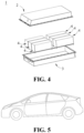
- Fig. 5 shows an apparatus as an example.
- the apparatus is an all-electric vehicle, a hybrid electric vehicle, a plug-in hybrid electric vehicle, or the like.
- a battery pack or a battery module may be used.
- Fig. 6 is a schematic view showing an alternate arrangement of a high compaction region and a low compaction region in a negative electrode plate in an embodiment of the present application, wherein the length directions of the high compaction region and the low compaction region are consistent with the length direction of the electrode plate.
- the lower part of Fig. 6 shows a schematic cross-sectional view of the electrode plate, wherein x 1 is the upper surface width of the low compaction region, x 2 is the lower surface width of the low compaction region, m i is the width of the high compaction region, and ⁇ 1 and ⁇ 2 are the included angles between the tangential directions on both sides of the low compaction region and the horizontal direction, respectively.
- Fig. 7 is a schematic view showing the directions of the regions with different densities and the direction of the tab in a negative electrode plate in an embodiment of the present application, wherein the directions of the regions with different densities are parallel, perpendicular and inclined to the direction of the tab, respectively.
- a nickel-cobalt-manganese (NCM) ternary material, a conductive agent carbon black, and a binder polyvinylidene fluoride (PVDF) in a weight ratio of 96.7: 1.7: 1.6 were stirred and mixed uniformly to obtain a positive electrode slurry; then the positive electrode slurry was uniformly coated on a positive electrode current collector, and then subjected to oven drying, cold pressing and slitting to obtain the positive electrode plate.
- NCM nickel-cobalt-manganese
- PVDF binder polyvinylidene fluoride
- an active substance artificial graphite, a conductive agent carbon black, a binder styrene butadiene rubber (SBR) and a thickener sodium hydroxymethyl cellulose (CMC) in a weight ratio of 96.8: 0.7: 1.3: 1.2 were dissolved in a solvent deionized water, mixed uniformly to prepare a negative electrode slurry, which was coated on a current collector.
- a solvent deionized water By regulating the water content in the slurry, negative electrode slurries with two viscosities were obtained, and by coating the slurries with different viscosities on the current collector, an electrode plate with alternating high and low coating weights were obtained.
- the density of high compaction region was 1.7g/cm 3
- the density of low compaction region was 1.3g/cm 3
- the number of the high compaction regions was the same as the number of the low compaction regions, and their average widths were also substantially the same.
- the upper and lower surface widths of the regions with different densities were measured by an off-line laser thickness gauge, and the density of each region was adjusted by the width of the coating region and the weight calculation. Subsequently, the negative electrode plate was obtained by oven drying, cold pressing and slitting.
- an organic solvent EC/EMC was mixed uniformly in a volume ratio of 3/7, and 12.5% of lithium salt LiPF 6 was added and dissolved in the organic solvent, and the mixture was stirred uniformly to obtain a corresponding electrolyte solution.
- An 8 ⁇ m PE porous film was used as the substrate, and a 2 ⁇ m thick ceramic coating was applied on both sides to serve as a separator.
- the positive electrode plate, the separator and the negative electrode plate prepared as described above were stacked in sequence, so that the separator was positioned between the positive electrode plate and the negative electrode plate and functioned to separate, and then a bare battery cell was obtained by winding, a tab was welded to the bare battery cell, the bare battery cell was put into an aluminum case, baked at 80 °C to remove water, and then the electrolyte solution was injected and sealed to obtain an uncharged battery. The uncharged battery was then subjected sequentially to standing, hot and cold pressing, chemical formation, shaping, capacity testing and other processes to obtain the lithium-ion secondary battery product of Example 1.
- Example 1 was repeated, except that the structure and density of the negative electrode active material layer of the negative electrode plate were as shown in Table 1 below (controlled by adjusting the coating amounts of the negative electrode slurries in different regions). As described above in each Example, the corresponding negative electrode plate and the corresponding lithium-ion secondary battery product were prepared.
- Example 1 was repeated, except that the negative electrode active material layer of the negative electrode plate did not have an alternating arrangement structure of high compaction region and low compaction region, instead had the same density.
- the densities were 1.6, 1.7, 1.8 and 1.9 g/cm 3 , respectively.
- the corresponding negative electrode plate and the corresponding lithium-ion secondary battery product were prepared.
- Measurement of the width of a specific region in the negative electrode active material layer of the negative electrode plate during the coating process, the thickness of the coated region was monitored in real time using an off-line laser thickness gauge, and the thickness was positively correlated to the coating weight, thus the width of the specific region was determined.
- the secondary battery comprising the negative electrode plate with an alternating arrangement structure of high compaction region and low compaction region in Examples of the present invention showed a significantly shorter charging time of 20-80% SOC, indicating a substantially improved charging performance. Additionally, as can be seen from the comparison between Examples of the present invention, the charging time of 20-80% SOC of the battery could be further improved by selecting the density difference between the high compaction region and the low compaction region as well as the difference between the upper surface width and the lower width of the low compaction region.
Landscapes
- Chemical & Material Sciences (AREA)
- Chemical Kinetics & Catalysis (AREA)
- Electrochemistry (AREA)
- General Chemical & Material Sciences (AREA)
- Engineering & Computer Science (AREA)
- Materials Engineering (AREA)
- Manufacturing & Machinery (AREA)
- Composite Materials (AREA)
- Inorganic Chemistry (AREA)
- Battery Electrode And Active Subsutance (AREA)
- Secondary Cells (AREA)
Abstract
Description
- The present application relates to a negative electrode plate comprising a negative electrode material layer having a structure in which a high compaction region and a low compaction region are continuously and alternately arranged, and the low compaction region has an upper surface width and a lower surface width with a width difference. The present application further relates to a preparation method of the negative electrode plate, a secondary battery comprising the negative electrode plate, a battery pack comprising the secondary battery and an electrical apparatus.
- Secondary batteries have become the most popular energy storage systems due to their low cost, long lifetime and good safety, and have been widely applied in all-electric vehicles, hybrid electric vehicles, smart grids and other fields. A secondary battery consists mainly of a positive electrode plate, a negative electrode plate, a separator and an electrolyte, wherein the negative electrode plate comprises a negative electrode current collector and a negative electrode material layer provided on at least one surface of the negative electrode current collector, and the negative electrode material layer comprises a negative electrode active substance. The negative electrode material layer needs to be infiltrated by an electrolyte solution, so that lithium intercalation can be achieved both on the surface and in the interior of the negative electrode material layer. To this end, in the prior art, the negative electrode material layer is generally made to contain a large number of pores to promote internal lithium intercalation, so that the electrolyte solution has a relatively high liquid transport rate inside the negative electrode material layer. In order to form internal pores, it is generally necessary to add a pore-forming agent to the mixture for preparing the negative electrode material layer. However, this increases the material costs, and moreover, these pore-forming agents need to be removed in the subsequent steps through cumbersome and expensive operations.
- Therefore, there is still a need to provide a new negative electrode plate, which can have an increased liquid transport rate and an improved charging performance, and can achieve pore formation without using any pore-forming agent, thereby reducing the production cost.
- The present application is made in view of the above topics, and an object thereof is to provide a negative electrode plate to solve the technical problems of insufficient liquid transport rate of the negative electrode plate and poor charging performance of the battery prepared therefrom.
- In order to achieve the above object, a first aspect of the present application is to provide a negative electrode plate comprising a negative electrode current collector and a negative electrode material layer provided on at least one surface of the negative electrode current collector, with the negative electrode material layer comprising a negative electrode active substance, wherein the negative electrode material layer has a structure in which a high compaction region and a low compaction region are continuously and alternately arranged, the high compaction region has a density of 1.6-1.9 g/cm3, the low compaction region has a density of 1.3-1.8 g/cm3, and the density difference between the high compaction region and the low compaction region is 0.1-0.6 g/cm3, optionally 0.2-0.4 g/cm3,
- Wherein the low compaction region has an upper surface width x1 and a lower surface width x2, and the difference between the upper surface width and the lower surface width is 0≤| x1- x2 |≤100mm.
- By comprising a negative electrode material layer with a specific structure in the negative electrode plate of the present application, it is possible to have different porosities in different regions within the material layer without using any pore-forming agent, thereby increasing the liquid transport rate of the electrolyte solution in the negative electrode plate, and in turn improving the charging performance.
- In any of embodiments, the difference between the upper surface width and the lower surface width of the low compaction region is 0≤|x1- x2 |≤120µm, optionally 60µm≤|x1- x2 |≤120µm, and further optionally 80µm≤|x1- x2 |≤120µm. By further adjusting the difference between the upper surface width and the lower surface width of the low compaction region, the shape of the low compaction region can be changed, thereby controlling the transport rate of the electrolyte solution in the negative electrode material layer.
- In any of embodiments, the width x of the low compaction region is 100µm-100mm, optionally 200µm-30mm. In any of embodiments, the width mi of the high compaction region is 10-100mm, optionally 20-60mm. The widths of the low compaction region and the high compaction region can be adjusted according to the length of the negative electrode plate to be prepared.
- In any of embodiments, the negative electrode plate satisfies the following formula: 0.1≤n*mi/L < 1, where n is the number of the low compaction region, mi is the width of the high compaction region, and L is the length of the electrode plate. In additional embodiments, the direction of the low compaction region is defined as Θ which satisfies Θ2≤Θ≤Θ1, wherein 0 < Θ1/ Θ2≤1, and Θ1 and Θ2 are the included angles between the tangential directions on both sides of the low compaction region and the horizontal direction, respectively.
- In any of embodiments, the cross-sectional structural shape of the low compaction region has a rectangular, trapezoidal or arc-shaped structure, or an irregular structure. In any of embodiments, the length directions of the low compaction region and the high compaction region are parallel to the direction of the negative electrode tab. In any of embodiments, the negative electrode current collector is a metal foil or a composite current collector, and the composite current collector comprises a high molecular material substrate layer and a metal layer formed on at least one surface of the high molecular material substrate layer. In additional embodiments, the negative electrode active substance is selected from one or more of graphite, soft carbon, hard carbon, mesocarbon microsphere, carbon fiber, carbon nanotube, elemental silicon, silicon-oxygen compound, silicon-carbon composite, and lithium titanate.
- In any of embodiments, the densities in the low compaction regions may be the same or different; and in the case of different densities, the density difference between each of the low compaction regions is ≤0.5 g/cm3.
- The present application further relates to a method for preparing the negative electrode plate of the first aspect of the present application, comprising the steps of:
- Forming regions with different negative electrode active substance contents by adjusting the viscosities and/or weights of the negative electrode active substance coated on the current collector in different regions thereof; and
- Cold pressing the negative electrode material layer so that it has the same thickness.
- A second aspect of the present application is to provide a secondary battery comprising a negative electrode plate selected from the first aspect of the present application.
- A third aspect of the present application is to provide a battery pack comprising a secondary battery selected from the second aspect of the present application.
- A fourth aspect of the present application is to provide an electrical apparatus comprising a secondary battery selected from the second aspect of the present application or a battery pack selected from the third aspect of the present application.
- In order to more clearly illustrate the technical solutions of the present application, the drawings to be used in Examples of the present application will be briefly introduced below. Apparently, the drawings described below are merely some Examples of the present application. For those of ordinary skills in the art, other drawings may also be obtained based on these drawings without making creative work.
-
Fig. 1 is a schematic view of a lithium-ion secondary battery in an embodiment of the present application. -
Fig. 2 is an exploded view of the lithium-ion secondary battery in an embodiment of the present application shown inFig. 1 . -
Fig. 3 is a schematic view of a battery pack in an embodiment of the present application. -
Fig. 4 is an exploded view of the battery pack in an embodiment of the present application shown inFig. 3 . -
Fig. 5 is a schematic view of an apparatus in which a battery pack in an embodiment of the present application is used as a power source. -
Fig. 6 is a schematic view showing an alternate arrangement of a high compaction region and a low compaction region in a negative electrode plate in an embodiment of the present application. -
Fig. 7 is a schematic view showing the directions of the regions with different densities and the direction of the tab in a negative electrode plate in an embodiment of the present application. -
- 1 Battery pack
- 2 Upper box body
- 3 Lower box body
- 4 Battery module
- 5. Lithium-ion secondary battery
- 51 Case
- 52 Electrode assembly
- 53 Cover plate
- For the sake of brevity, the present application specifically discloses some numerical ranges. However, any lower limit can be combined with any upper limit to form a range not explicitly recited; and any lower limit can be combined with another lower limit to form a range not explicitly recited, and likewise, any upper limit can be combined with any another upper limit to form a range not explicitly recited. Further, each individually disclosed point or single value itself may serve as a lower limit or an upper limit in combination with any other point or single value or with other lower limits or upper limits to form a range not explicitly recited.
- With the rapid popularization of electric vehicles such as electric automobiles, the market's demand for lithium-ion batteries with strong charging performance is becoming increasingly urgent. To improve the charging performance of lithium batteries, an effective way is to increase the infiltration rate of the electrolyte solution into the negative electrode plate, so that even the lithium intercalation capability of the negative electrode active substance inside the negative electrode plate can be effectively maintained. However, as the surface of the negative electrode plate is easily passivated after lithium intercalation, and the intercalated lithium ions easily block the pores on the surface of the electrode plate, it is difficult for the subsequent lithium ions to penetrate deeply into the interior of the negative electrode active material layer for lithium intercalation. A conventional method in the prior art is to add a pore-forming agent into the mixture for preparing the negative electrode active material layer, so that the porosity inside the formed negative electrode active material layer is significantly increased. However, due to the uniformity of the porosity in the negative electrode active material layer, it is still difficult for the electrolyte solution to penetrate deeply into the interior of the negative electrode active material layer, as the liquid transport kinetics is insufficient in the case of uniform porosity. Additionally, in the prior art, one or more pore-forming agents selected from calcium oxide, magnesium oxide, germanium oxide and tin oxide are generally used, and these pore-forming agents need to be removed in a subsequent step. This not only increases the material cost, but also makes the preparation of the negative electrode plate more complicated and cumbersome.
- Therefore, there is a need in the art to provide a new negative electrode plate, which has improved electrolyte solution transport rate and charging performance, and can be prepared without the use of pore-forming agents.
- Specifically, a first aspect of the present application is to provide a negative electrode plate comprising a negative electrode current collector and a negative electrode material layer provided on at least one surface of the negative electrode current collector, with the negative electrode material layer comprising a negative electrode active substance, wherein the negative electrode material layer has a structure in which a high compaction region and a low compaction region are continuously and alternately arranged, the high compaction region has a density of 1.6-1.9 g/cm3, the low compaction region has a density of 1.3-1.8 g/cm3, and the density difference between the high compaction region and the low compaction region is 0.1-0.6 g/cm3, optionally 0.2-0.4 g/cm3,
- Wherein the low compaction region has an upper surface width x1 and a lower surface width x2, and the difference between the upper surface width and the lower surface width is 0≤| x1- x2 |≤100mm.
- The inventors have found that the negative electrode plate of the present application can significantly improve the transport rate of the electrolyte solution by comprising a negative electrode material layer with a specific structure, thereby obtaining improved charging performance. Without being bound by any theory, the inventors believe that by coating negative electrode active substances with different weights when preparing the active material layer of the negative electrode plate and pressing the negative electrode material layer to the same thickness in the subsequent cold pressing stage, different regions of the material layer can have different densities. By different densities, it means different porosity in each region; a region with low density has a high porosity, while a region with high density has a low porosity. As the electrolyte solution is transported from one region to the adjacent region, the different porosities of the adjacent regions allow the transport kinetics of the electrolyte solution to be improved, and the transport rate is increased, thereby increasing its infiltration capability into the negative electrode plate. The factors affecting the transport rate include both the density difference between adjacent regions, but also the shape features of the low compaction region, that is, the width difference between the upper and lower surfaces. The inventors have found that, by controlling the density difference between the high compaction region and the low compaction region, and the difference between the upper surface width and the lower surface width of the low compaction region within a specific range, a negative electrode plate with significantly improved liquid transport rate and charging performance can be obtained.
- From a practical point of view, the respective densities of the high compaction region and the low compaction region of the negative electrode material layer of the negative electrode plate should be within a reasonable range, thus limiting the respective density ranges of the high compaction region and the low compaction region. The density of each region refers to the density of the negative electrode active substance contained therein. Additionally, one of the widths of the upper and lower surfaces of the low compaction region can be zero, i.e., including the case where the region intersects the surface at only one point. In particular, the negative electrode plate does not contain any pore-forming agent.
- In some embodiments, the difference between the upper surface width and the lower surface width of the low compaction region is 0≤|x1- x2 |≤120µm, optionally 60µm≤|x1- x2 |≤120µm, and further optionally 80µm≤|x1- x2 |≤120µm. By further adjusting the difference between the upper surface width and the lower surface width of the low compaction region, the shape of the low compaction region can be changed, thereby controlling the transport rate of the electrolyte solution in the negative electrode material layer.
- In some embodiments, the width x of the low compaction region is 100µm-100mm, optionally 200µm-30mm. In some embodiments, the width mi of the high compaction region is 10-100mm, optionally 20-60mm. The width x of the low compaction region and the width mi of the high compaction region are the average width of each region, respectively. The widths of the low compaction region and the high compaction region can be adjusted according to the length of the negative electrode plate to be prepared. If the length of each region is too long, the transport rate of the electrolyte solution in a single region will slow down, and the improvement effect brought by the difference of porosity between different regions is not obvious; and if the length of each region is too short, not only the processing will be difficult, but also the liquid transport rate will be unstable.
- In some embodiments, the negative electrode plate satisfies the following formula: 0.1≤n*mi/L < 1, where n is the number of the low compaction region, mi is the width of the high compaction region, and L is the length of the electrode plate. The inventors have found that when the negative electrode plate satisfies the requirements of the above formula, the charging performance thereof is further improved. The total width of the high compaction region in the length direction of the electrode plate should not be too low, otherwise the improvement effect brought by the difference of porosity is not obvious.
- In some other embodiments, the direction of the low compaction region is defined as Θ which satisfies Θ2≤Θ≤Θ1, wherein 0 < Θ1/ Θ2≤1, and Θ1 and Θ2 are the included angles between the tangential directions on both sides of the low compaction region and the horizontal direction, respectively. The above formula further defines the shape of the low compaction region on the transverse cross-section of the negative electrode plate, so that the transport rate of the electrolyte solution in the region can be adjusted by changing the shape of the region. In some embodiments, the cross-sectional structural shape of the low compaction region has a rectangular, trapezoidal or arc-shaped structure, or an irregular structure. In particular, the structural shape of the cross-section of the low compaction region is rectangular or trapezoidal, wherein in the case of trapezoid, the difference between the upper and lower widths of the cross-section of the low compaction region is ≤100µm.
- In some embodiments, the length directions of the low compaction region and the high compaction region are parallel to the direction of the negative electrode tab. The length directions of the low compaction region and the high compaction region are parallel to the length direction of the negative electrode plate. The inventors have found that, as compared with other directional arrangements, when the length directions of the low compaction region and the high compaction region are parallel to the direction of the negative electrode tab, the infiltration rate of the electrolyte solution in the active material layer of the negative electrode plate is the largest. The composition of the active material layer of the negative electrode plate is not particularly limited, and materials and structures conventionally used in the art can be used. For example, the negative electrode plate can comprise a negative electrode current collector and a negative electrode material layer provided on at least one surface of the negative electrode current collector. In some embodiments, the negative electrode current collector is a metal foil or a composite current collector comprising a high molecular material substrate layer and a metal layer formed on at least one surface of the high molecular material substrate. In some other embodiments, the negative electrode material layer comprises a negative electrode active substance, and the negative electrode active substance is selected from one or more of graphite, soft carbon, hard carbon, mesocarbon microsphere, carbon fiber, carbon nanotube, elemental silicon, silicon-oxygen compound, silicon-carbon composite, and lithium titanate.
- In some embodiments, the densities in the low compaction regions may be the same or different; and in the case of different densities, the density difference between each of the low compaction regions is ≤0.5 g/cm3. When the density difference between each of the low compaction regions is greater than 0.5 g/cm3, the concentration polarization in the active material layer is too large, so that the improvement of the infiltration rate of the electrolyte solution is not significant.
- The present application further relates to a method for preparing the negative electrode plate according to the first aspect of the present application, comprising the steps of:
- Forming regions with different negative electrode active substance contents by adjusting the viscosities and/or weights of the negative electrode active substance coated on the current collector in different regions thereof; and
- Cold pressing the negative electrode material layer so that it has the same thickness.
- The negative electrode plate of the present invention has no particular requirements for the current collector and the negative electrode active material, and thus various materials conventionally used in the field of batteries can be used. Specific materials can be found in the detailed description of the negative electrode plate below. For the preparation of the negative electrode plate, a conventional preparation method can also be used, for example, by formulating a negative electrode slurry comprising a negative electrode active substance, a conductive agent, a binder and a thickener, and coating the resulting slurry on different regions of the current collector at different weights, thus a negative electrode material layer having regions with different coating weights can be formed on the current collector. Subsequently, the negative electrode plate can be obtained by oven drying, cold pressing and slitting. During cold pressing, the thickness of the negative electrode material layer is pressed to a uniform thickness, so that the negative electrode material layer has a substantially flat surface. At this time, as the weight of the negative electrode slurry coated in each region of the negative electrode material layer is different, the density in each region is also different. With different densities, the porosities thereof are also different. Finally, a negative electrode plate having a plurality of alternately arranged regions with different porosities is obtained. In particular, the method for preparing the negative electrode plate described in the present application does not include the use of any pore-forming agent.
- A second aspect of the present application is to provide a secondary battery comprising a negative electrode plate selected from the first aspect of the present application.
- A third aspect of the present application is to provide a battery pack comprising a secondary battery selected from the second aspect of the present application.
- A fourth aspect of the present application is to provide an electrical apparatus comprising a secondary battery selected from the second aspect of the present application or a battery pack selected from the third aspect of the present application.
- The materials of the components of the secondary battery mentioned in the present application can be selected within a wide range. In some embodiments, the secondary battery is particularly a lithium-ion secondary battery. The battery cell of the lithium-ion secondary battery will be described in detail below.
- Generally, a lithium-ion secondary battery comprises a positive electrode plate, a negative electrode plate, a separator, and an electrolyte. During charging and discharging of the battery, active ions are intercalated and deintercalated back and forth between the positive electrode plate and the negative electrode plate. The separator is provided between the positive electrode plate and the negative electrode plate and functions to separate. The electrolyte serves to conduct ions between the positive electrode plate and the negative electrode plate.
- The electrolyte solution serves to conduct ions between the positive electrode plate and the negative electrode plate. The electrolyte solution comprises an electrolyte salt and a solvent.
- In the present application, the electrolyte salt may be an electrolyte salt commonly used in lithium-ion secondary batteries, such as a lithium salt, including the above-mentioned lithium salt as a highly heat-stable salt, a lithium salt as a low-impedance additive, or a lithium salt that inhibits aluminum foil corrosion. As an example, the electrolyte salt may be selected from one or more of lithium hexafluorophosphate (LiPF6), lithium tetrafluoroborate (LiBF4), lithium hexafluoroarsenate (LiAsF6), lithium bis(fluorosulfonyl)imide (LiFSI), lithium bis(trifluoromethanesulfonyl)imide (LiTFSI), lithium trifluoromethanesulfonate (LiTFS), lithium difluoro(oxalato)borate (LiDFOB), lithium difluorophosphate (LiPO2F2), lithium difluoro bis(oxalato)phosphate (LiDFOP), lithium fluorosulfonate (LiSO3F), difluorodioxalate (NDFOP), Li2F(SO2N)2SO2F, KFSI, CsFSI, Ba(FSI)2 and LiFSO2NSO2CH2CH2CF3.
- The type of the solvent is not particularly limited, and may be selected according to actual needs. In some embodiments, the solvent is a non-aqueous solvent. Optionally, the solvent may comprise one or more of a chain carbonate, a cyclic carbonate, and a carboxylate. In some embodiments, the solvent may be selected from one or more of ethylene carbonate (EC), propylene carbonate (PC), ethyl methyl carbonate (EMC), diethyl carbonate (DEC), dimethyl carbonate (DMC), dipropyl carbonate (DPC), methyl propyl carbonate (MPC), ethyl propyl carbonate (EPC), butylene carbonate (BC), fluoroethylene carbonate (FEC), methyl formate (MF), methyl acetate (MA), ethyl acetate (EA), propyl acetate (PA), methyl propionate (MP), ethyl propionate (EP), propyl propionate (PP), methyl butyrate (MB), ethyl butyrate (EB), 1,4-butyrolactone (GBL), tetrahydrofuran, sulfolane (SF), methylsulfonylmethane (MSM), methyl ethyl sulfone (EMS), and ethyl sulfonyl ethane (ESE).
- In some embodiments, the electrolyte solution optionally further comprises other additives. For example, the additives may include a negative electrode film-forming additive, or may include a positive electrode film-forming additive, or may further include an additive that can improve some performance of the battery, such as an additive that improves overcharge performance of the battery, an additive that improves high temperature performance of the battery, and an additive that improves low temperature performance of the battery. As an example, the additive is selected from at least one of a cyclic carbonate compound containing an unsaturated bond, a halogen-substituted cyclic carbonate compound, a sulfate compound, a sulfite compound, a sultone compound, a disulfonic acid compound, a nitrile compound, an aromatic compound, an isocyanate compound, a phosphazene compound, a cyclic anhydride compound, a phosphite compound, a phosphate compound, a borate compound, and a carboxylate compound.
- The positive electrode plate comprises a positive electrode current collector and a positive electrode active substance layer provided on at least one surface of the positive electrode current collector, and the positive electrode active substance layer comprises a positive electrode active material and a conductive agent.
- As an example, the positive electrode current collector has two opposite surfaces in its own thickness direction, and the positive electrode active substance layer is provided on either one or both of the two opposite surfaces of the positive electrode current collector.
- In the lithium-ion secondary battery of the present application, the positive electrode current collector can be a metal foil or a composite current collector. For example, an aluminum foil can be used as the metal foil. The composite current collector may comprise a high molecular material substrate layer and a metal layer formed on at least one surface of the high molecular material substrate layer. The composite current collector may be formed by forming a metal material (such as aluminium, aluminium alloy, nickel, nickel alloy, titanium, titanium alloy, silver and silver alloy, etc.) on a high molecular material substrate (substrates such as polypropylene (PP), polyethylene terephthalate (PET), polybutylene terephthalate (PBT), polystyrene (PS), polyethylene (PE), etc.).
- The positive electrode active substance layer provided on the surface of the positive electrode current collector comprises a positive electrode active material. The positive electrode active material used in the present application may be any conventional positive electrode active material used in secondary batteries. In some embodiments, the positive electrode active material may comprise one or more selected from lithium transition metal oxides, lithium-containing phosphates with olivine structure and their respective modified compounds. Examples of lithium transition metal oxides may include, but are not limited to, one or more of a lithium-cobalt oxide, a lithium-nickel oxide, a lithium-manganese oxide, a lithium-nickel-cobalt oxide, a lithium-manganese-cobalt oxide, a lithium-nickel-manganese oxide, a lithium-nickel-cobalt-manganese oxide, a lithium-nickel-cobalt-aluminum oxide, and modified compounds thereof. Examples of lithium-containing phosphate with olivine structure may include, but are not limited to, one or more of lithium iron phosphate, a composite of lithium iron phosphate and carbon, lithium manganese phosphate, a composite of lithium manganese phosphate and carbon, lithium manganese iron phosphate, a composite of lithium manganese iron phosphate and carbon, and modified compounds thereof. These materials are all commercially available. The surface of the positive electrode active material may be coated with carbon.
- The positive electrode active substance layer optionally comprises a conductive agent. However, the type of the conductive agent is not particularly limited, and those skilled in the art can make a selection according to actual needs. As an example, the conductive agent for the positive electrode material may be selected from one or more of superconducting carbon, acetylene black, carbon black, Ketjen black, carbon dot, carbon nanotube, graphene, and carbon nanofiber.
- The positive electrode active substance layer further comprises a binder. The binder is the binder composition described above. In addition to the binder composition described above, the binder may further contain other binders. As an example, the other binders may be one or more of styrene butadiene rubber (SBR), water-based acrylic resin, polyvinylidene fluoride (PVDF), polytetrafluoroethylene (PTFE), ethylene-vinyl acetate copolymer (EVA), polyacrylic acid (PAA), carboxymethyl cellulose (CMC), polyvinyl alcohol (PVA), and polyvinyl butyral (PVB).
- In the present application, the positive electrode plate can be prepared according to a method known in the art. As an example, a carbon-coated positive electrode active material, a conductive agent, and an aqueous binder can be dispersed in a solvent (such as water) to form a uniform positive electrode slurry; and the positive electrode slurry is coated on a positive electrode current collector, and the positive electrode plate is obtained after oven drying, cold pressing and other processes.
- The negative electrode plate comprises a negative electrode current collector and a negative electrode material layer provided on at least one surface of the negative electrode current collector, and the negative electrode material layer comprises a negative electrode active substance.
- As an example, the negative electrode current collector has two opposite surfaces in its own thickness direction, and the negative electrode material layer is provided on either one or both of the two opposite surfaces of the negative electrode current collector.
- In the lithium-ion secondary battery of the present application, the negative electrode current collector may be a metal foil or a composite current collector. For example, a copper foil can be used as the metal foil. The composite current collector may comprise a high molecular material substrate layer and a metal layer formed on at least one surface of the high molecular material substrate. The composite current collector may be formed by forming a metal material (such as copper, copper alloy, nickel, nickel alloy, titanium, titanium alloy, silver and silver alloy, etc.) on a high molecular material substrate (substrates such as polypropylene (PP), polyethylene terephthalate (PET), polybutylene terephthalate (PBT), polystyrene (PS), polyethylene (PE), etc.).
- In the lithium-ion secondary battery of the present application, the negative electrode material layer generally comprises a negative electrode active substance and an optional binder, an optional conductive agent, and other optional adjuvants, and is generally formed by coating a negative electrode slurry and drying. The negative electrode slurry is generally formed by dispersing the negative electrode active substance and the optional conductive agent and binder in a solvent, and stirring uniformly. The solvent may be N-methyl pyrrolidone (NMP) or deionized water.
- The specific type of the negative electrode active substance is not limited, an active substance known in the art that can be used for the negative electrode of lithium-ion secondary batteries can be used, and those skilled in the art can select according to actual needs. As an example, the negative electrode active substance may be selected from one or more of graphite, soft carbon, hard carbon, mesocarbon microsphere, carbon fiber, carbon nanotube, elemental silicon, silicon-oxygen compound, silicon-carbon composite, and lithium titanate.
- As an example, the conductive agent may be selected from one or more of superconducting carbon, acetylene black, carbon black, Ketjen black, carbon dot, carbon nanotube, graphene, and carbon nanofiber.
- The negative electrode active substance layer further comprises a binder. The binder is the binder composition described above. In addition to the binder composition described above, the binder may further contain other binders. As an example, the other binders may be selected from one or more of styrene butadiene rubber (SBR), polyacrylic acid (PAA), sodium polyacrylate (PAAS), polyacrylamide (PAM), polyvinyl alcohol (PVA), sodium alginate (SA), polymethacrylic acid (PMAA), and carboxymethyl chitosan (CMCS).
- The other optional adjuvants are for example a thickener (such as sodium carboxymethyl cellulose (CMC-Na)) and the like.
- The lithium-ion secondary battery using an electrolyte solution further comprises a separator. The separator is provided between the positive electrode plate and the negative electrode plate and functions to separate. The type of the separator is not particularly limited in the present application, and any well-known separator with a porous structure having good chemical stability and mechanical stability may be selected. In some embodiments, the material of the separator may be selected from one or more of glass fiber, non-woven cloth, polyethylene, polypropylene, and polyvinylidene fluoride. The separator may be a single-layer film or a multi-layer composite film, which is not particularly limited. When the separator is a multi-layer composite film, the material of each layer may be the same or different, which is not particularly limited.
- In some embodiments, the positive electrode plate, the negative electrode plate, and the separator can be made into an electrode assembly by a winding process or a stacking process.
- In some embodiments, the secondary battery may comprise an outer package. The outer package can be used to encapsulate the above-mentioned electrode assembly and electrolyte.
- In some embodiments, the outer package of the secondary battery may be a hard shell, e.g., a hard plastic shell, an aluminum shell, a steel shell, etc. The outer package of the secondary battery may also be a soft pack, such as a bag-type soft pack. The material of the soft pack may be plastic, and examples of the plastic include polypropylene (PP), polybutylene terephthalate (PBT), polybutylene succinate (PBS), and the like.
- The present application has no particular limitation on the shape of the secondary battery, which can be cylindrical, square or any other shape. For example,
Fig. 1 is a lithium-ionsecondary battery 5 with a square structure as an example. - In some embodiments, referring to
Fig. 2 , the outer package may comprise acase 51 and acover plate 53. Here, thecase 51 can comprise a bottom plate and a side plate connected to the bottom plate, with the bottom plate and the side plate enclosing to form an accommodating cavity. Thecase 51 has an opening that communicates with the accommodating cavity, and thecover plate 53 can cover the opening to close the accommodating cavity. The positive electrode plate, the negative electrode plate, and the separator may be formed into anelectrode assembly 52 by a winding process or a stacking process. Theelectrode assembly 52 is encapsulated within the accommodating cavity. The electrolyte solution impregnates theelectrode assembly 52. The number of theelectrode assemblies 52 contained in the lithium-ionsecondary battery 5 may be one or more, which can be selected by those skilled in the art according to specific actual needs. - In some embodiments, the lithium-ion secondary batteries may be assembled into a battery module 4, the number of the lithium-ion secondary batteries contained in the battery module 4 may be one or more, and the specific number may be selected by those skilled in the art according to the application and capacity of the battery module 4. In the battery module 4, the plurality of lithium-ion
secondary batteries 5 may be sequentially arranged along the length direction of the battery module. Of course, they can be arranged in any other way. The plurality of lithium-ionsecondary batteries 5 can be further fixed by fasteners. Optionally, the battery module 4 may further comprise a case having an accommodating space in which the plurality of lithium-ionsecondary batteries 5 are accommodated. - In some embodiments, the above-mentioned lithium-ion
secondary batteries 5 or battery modules 4 can be assembled into abattery pack 1, and the number of the lithium-ionsecondary batteries 5 or the battery modules 4 contained in thebattery pack 1 can be selected by those skilled in the art according to the application and capacity of thebattery pack 1. -
Figs. 3 and4 show abattery pack 1 as an example. Referring toFigs. 3 and4 , thebattery pack 1 may comprise a battery box and a plurality of battery cells provided in the battery box. The battery box comprises anupper box body 2 and alower box body 3, and theupper box body 2 can cover thelower box body 3 to form a closed space for accommodating the battery cells. - Additionally, the present application further provides an apparatus comprising the battery pack provided by the present application. The battery pack can be used as a power source of the apparatus, and can also be used as an energy storage unit of the apparatus. The apparatus may be, but is not limited to, a mobile device (e.g., a mobile phone and a laptop), an electric vehicle (e.g., an all-electric vehicle, a hybrid electric vehicle, a plug-in hybrid electric vehicle, an electric bicycle, an electric scooter, an electric golf cart, and an electric truck), an electric train, a ship and a satellite, an energy storage system, and the like. For the apparatus, a battery pack can be selected according to its use requirements.
-
Fig. 5 shows an apparatus as an example. The apparatus is an all-electric vehicle, a hybrid electric vehicle, a plug-in hybrid electric vehicle, or the like. In order to meet the requirements of the apparatus for high power and high energy density of lithium-ion secondary batteries, a battery pack or a battery module may be used. -
Fig. 6 is a schematic view showing an alternate arrangement of a high compaction region and a low compaction region in a negative electrode plate in an embodiment of the present application, wherein the length directions of the high compaction region and the low compaction region are consistent with the length direction of the electrode plate. The lower part ofFig. 6 shows a schematic cross-sectional view of the electrode plate, wherein x1 is the upper surface width of the low compaction region, x2 is the lower surface width of the low compaction region, mi is the width of the high compaction region, and Θ1 and Θ2 are the included angles between the tangential directions on both sides of the low compaction region and the horizontal direction, respectively. -
Fig. 7 is a schematic view showing the directions of the regions with different densities and the direction of the tab in a negative electrode plate in an embodiment of the present application, wherein the directions of the regions with different densities are parallel, perpendicular and inclined to the direction of the tab, respectively. - Examples of the present application will be described hereinafter. The Examples described below are exemplary and only used to explain the present application, and are not to be construed as limiting the present application. Where specific techniques or conditions were not specified in the Examples, the techniques or conditions described in the literatures in the art or the product specifications were followed. The reagents or instruments used, where the manufacturer was not indicated, are conventional products that are commercially available. If there was no special indication, all content ratios were weight ratios, and all experiments were carried out at normal temperature (25°C) and normal pressure.
- A nickel-cobalt-manganese (NCM) ternary material, a conductive agent carbon black, and a binder polyvinylidene fluoride (PVDF) in a weight ratio of 96.7: 1.7: 1.6 were stirred and mixed uniformly to obtain a positive electrode slurry; then the positive electrode slurry was uniformly coated on a positive electrode current collector, and then subjected to oven drying, cold pressing and slitting to obtain the positive electrode plate.
- Subsequently, an active substance artificial graphite, a conductive agent carbon black, a binder styrene butadiene rubber (SBR) and a thickener sodium hydroxymethyl cellulose (CMC) in a weight ratio of 96.8: 0.7: 1.3: 1.2 were dissolved in a solvent deionized water, mixed uniformly to prepare a negative electrode slurry, which was coated on a current collector. By regulating the water content in the slurry, negative electrode slurries with two viscosities were obtained, and by coating the slurries with different viscosities on the current collector, an electrode plate with alternating high and low coating weights were obtained. Here, the density of high compaction region was 1.7g/cm3, the density of low compaction region was 1.3g/cm3, the number of the high compaction regions was the same as the number of the low compaction regions, and their average widths were also substantially the same. Here, the upper and lower surface widths of the regions with different densities were measured by an off-line laser thickness gauge, and the density of each region was adjusted by the width of the coating region and the weight calculation. Subsequently, the negative electrode plate was obtained by oven drying, cold pressing and slitting.
- In an argon atmosphere glove box (H2O<0.1ppm, O2<0.1ppm), an organic solvent EC/EMC was mixed uniformly in a volume ratio of 3/7, and 12.5% of lithium salt LiPF6 was added and dissolved in the organic solvent, and the mixture was stirred uniformly to obtain a corresponding electrolyte solution.
- An 8µm PE porous film was used as the substrate, and a 2µm thick ceramic coating was applied on both sides to serve as a separator.
- The positive electrode plate, the separator and the negative electrode plate prepared as described above were stacked in sequence, so that the separator was positioned between the positive electrode plate and the negative electrode plate and functioned to separate, and then a bare battery cell was obtained by winding, a tab was welded to the bare battery cell, the bare battery cell was put into an aluminum case, baked at 80 °C to remove water, and then the electrolyte solution was injected and sealed to obtain an uncharged battery. The uncharged battery was then subjected sequentially to standing, hot and cold pressing, chemical formation, shaping, capacity testing and other processes to obtain the lithium-ion secondary battery product of Example 1.
- Example 1 was repeated, except that the structure and density of the negative electrode active material layer of the negative electrode plate were as shown in Table 1 below (controlled by adjusting the coating amounts of the negative electrode slurries in different regions). As described above in each Example, the corresponding negative electrode plate and the corresponding lithium-ion secondary battery product were prepared.
- Example 1 was repeated, except that the negative electrode active material layer of the negative electrode plate did not have an alternating arrangement structure of high compaction region and low compaction region, instead had the same density. For Comparative examples 1-4, the densities were 1.6, 1.7, 1.8 and 1.9 g/cm3, respectively. As described above in each Comparative example, the corresponding negative electrode plate and the corresponding lithium-ion secondary battery product were prepared.
- The negative electrode plates and the lithium-ion secondary batteries of Examples 1-10 and Comparative examples 1-4 were tested, and the results were shown in Table 1 below.
Table 1: No. Density of low compaction region /g/cm3 compacted density difference between high and low compaction regions /g/cm3 Density of high compaction region /g/cm3 |x1- x2| /µm Charging time of 20-80% SOC /minute Example 1 1.3 0.4 1.7 100 7.2 Example 2 1.3 0.3 1.6 100 6.0 Example 3 1.5 0.2 1.7 100 8.0 Example 4 1.5 0.1 1.6 100 12.0 Example 5 1.5 0.3 1.8 100 12.0 Example 6 1.5 0.3 1.8 60 14.0 Example 7 1.5 0.3 1.8 0 16.0 Example 8 1.7 0.1 1.8 100 19.0 Example 9 1.7 0.2 1.9 100 20.0 Example 10 1.8 0.1 1.9 100 22.0 Comparative example 1 / / 1.6 / 14.4 Comparative example 2 / / 1.7 / 18.0 Comparative example 3 / / 1.8 / 20.0 Comparative example 4 / / 1.9 / 24.0 - Measurement of the compacted density of a specific region in the active material layer of the negative electrode plate: during the coating process, the thickness of the coated region was monitored in real time using an off-line laser thickness gauge, and the thickness was positively correlated to the coating weight. An electrode plate in a specific region was taken and weighed, and the following formula was used to calculate the compacted density of the specific region:

- Measurement of the width of a specific region in the negative electrode active material layer of the negative electrode plate: during the coating process, the thickness of the coated region was monitored in real time using an off-line laser thickness gauge, and the thickness was positively correlated to the coating weight, thus the width of the specific region was determined.
- Measurement of the charging performance of lithium-ion secondary battery: the charging time of 20-80% SOC of the battery was measured by three-electrode test method.
- As can be seen from the measurement results in the above Table, compared with the negative electrode plate with uniform density in Comparative examples, the secondary battery comprising the negative electrode plate with an alternating arrangement structure of high compaction region and low compaction region in Examples of the present invention showed a significantly shorter charging time of 20-80% SOC, indicating a substantially improved charging performance. Additionally, as can be seen from the comparison between Examples of the present invention, the charging time of 20-80% SOC of the battery could be further improved by selecting the density difference between the high compaction region and the low compaction region as well as the difference between the upper surface width and the lower width of the low compaction region.
- While the present application has been described with reference to Examples, various modifications may be made and components therein may be replaced with equivalents without departing from the scope of the present application. In particular, the technical features mentioned in the various Examples can be combined in any manner as long as there is no structural conflict. The present application is not limited to the specific Examples disclosed herein, but rather includes all technical solutions falling within the scope of the claims.
Claims (16)
- A negative electrode plate, comprising a negative electrode current collector and a negative electrode material layer provided on at least one surface of the negative electrode current collector, with the negative electrode material layer comprising a negative electrode active substance, wherein the negative electrode material layer has a structure in which a high compaction region and a low compaction region are continuously and alternately arranged, the high compaction region has a density of 1.6-1.9 g/cm3, the low compaction region has a density of 1.3-1.8 g/cm3, and the density difference between the high compaction region and the low compaction region is 0.1-0.6 g/cm3, optionally 0.2-0.4 g/cm3,
Wherein the low compaction region has an upper surface width x1 and a lower surface width x2, and the difference between the upper surface width and the lower surface width is 0≤| x1- x2 |≤100mm. - The negative electrode plate according to claim 1, wherein the difference between the upper surface width and the lower surface width of the low compaction region is 0≤|x1- x2 |≤120µm, optionally 60µm≤|x1- x2 |≤120µm, and further optionally 80µm≤|x1- x2 |≤120µm.
- The negative electrode plate according to any one of claims 1 to 2, wherein the width x of the low compaction region is 100µm-100mm, and optionally 200µm-30mm.
- The negative electrode plate according to any one of claims 1 to 3, wherein the width mi of the high compaction region is 10-100mm, and optionally 20-60mm.
- The negative electrode plate according to claim 4, which satisfies the following formula: 0.1≤n*mi/L<1, where n is the number of the low compaction region, mi is the width of the high compaction region, and L is the length of the electrode plate.
- The negative electrode plate according to any one of claims 1 to 5, wherein the direction of the low compaction region is defined as Θ which satisfies Θ2≤Θ≤Θ1, wherein 0<Θ1/ Θ2≤1, and Θ1 and Θ2 are the included angles between the tangential directions on both sides of the low compaction region and the horizontal direction, respectively.
- The negative electrode plate according to any one of claims 1 to 6, wherein the cross-sectional structural shape of the low compaction region has a rectangular, trapezoidal or arc-shaped structure, or an irregular structure.
- The negative electrode plate according to any one of claims 1 to 7, wherein the length directions of the low compaction region and the high compaction region are parallel to the direction of the negative electrode tab.
- The negative electrode plate according to any one of claims 1 to 8, wherein the negative electrode current collector is a metal foil or a composite current collector comprising a high molecular material substrate layer and a metal layer formed on at least one surface of the high molecular material substrate.
- The negative electrode plate according to any one of claims 1 to 9, wherein the negative electrode active substance is selected from one or more of graphite, soft carbon, hard carbon, mesocarbon microsphere, carbon fiber, carbon nanotube, elemental silicon, silicon-oxygen compound, silicon-carbon composite, and lithium titanate.
- The negative electrode plate according to any one of claims 1 to 10, wherein the densities in the low compaction regions may be the same or different; and in the case of different densities, the density difference between each of the low compaction regions is less than 0.5 g/cm3.
- A method for preparing the negative electrode plate according to any one of claims 1 to 11, comprising the steps of:forming regions with different negative electrode active substance contents by adjusting the viscosities and/or weights of the negative electrode active substance coated on the current collector in different regions of the current collector; andcold pressing the negative electrode material layer so that it has the same thickness.
- The method according to claim 12, wherein no pore-forming agent is used.
- A secondary battery, comprising the negative electrode plate according to any one of claims 1 to 11.
- A battery pack, comprising the secondary battery according to claim 14.
- An electrical apparatus, comprising the secondary battery according to claim 14 or the battery pack according to claim 15.
Applications Claiming Priority (1)
| Application Number | Priority Date | Filing Date | Title |
|---|---|---|---|
| PCT/CN2022/122013 WO2024065250A1 (en) | 2022-09-28 | 2022-09-28 | Negative electrode sheet and battery manufactured therefrom |
Publications (2)
| Publication Number | Publication Date |
|---|---|
| EP4510209A1 true EP4510209A1 (en) | 2025-02-19 |
| EP4510209A4 EP4510209A4 (en) | 2026-01-21 |
Family
ID=90475272
Family Applications (2)
| Application Number | Title | Priority Date | Filing Date |
|---|---|---|---|
| EP22959898.2A Pending EP4510209A4 (en) | 2022-09-28 | 2022-09-28 | NEGATIVE ELECTRODE FILM AND BATTERY MADE FROM IT |
| EP23870595.8A Pending EP4510212A4 (en) | 2022-09-28 | 2023-09-21 | Negative electrode film and manufacturing method therefor, secondary battery, battery pack and electrical device |
Family Applications After (1)
| Application Number | Title | Priority Date | Filing Date |
|---|---|---|---|
| EP23870595.8A Pending EP4510212A4 (en) | 2022-09-28 | 2023-09-21 | Negative electrode film and manufacturing method therefor, secondary battery, battery pack and electrical device |
Country Status (4)
| Country | Link |
|---|---|
| US (2) | US20250174656A1 (en) |
| EP (2) | EP4510209A4 (en) |
| CN (1) | CN118541820A (en) |
| WO (2) | WO2024065250A1 (en) |
Families Citing this family (1)
| Publication number | Priority date | Publication date | Assignee | Title |
|---|---|---|---|---|
| US20250283946A1 (en) * | 2024-03-08 | 2025-09-11 | GM Global Technology Operations LLC | Reference electrode management for a battery cell |
Family Cites Families (16)
| Publication number | Priority date | Publication date | Assignee | Title |
|---|---|---|---|---|
| JP4649113B2 (en) * | 2004-01-20 | 2011-03-09 | 株式会社東芝 | Nonaqueous electrolyte secondary battery |
| JP2012048955A (en) * | 2010-08-26 | 2012-03-08 | Sanyo Electric Co Ltd | Negative electrode for lithium ion secondary battery, lithium ion secondary battery, and method for manufacturing negative electrode for lithium ion secondary battery |
| JP2016058247A (en) * | 2014-09-10 | 2016-04-21 | 凸版印刷株式会社 | Electrode for lithium ion secondary battery and lithium ion secondary battery |
| CN108336297B (en) * | 2017-12-29 | 2021-10-08 | 惠州市纬世新能源有限公司 | Preparation method of lithium ion battery pole piece |
| CN110943222B (en) * | 2019-04-15 | 2021-01-12 | 宁德时代新能源科技股份有限公司 | Electrode plate and electrochemical device |
| CN110112366A (en) * | 2019-06-18 | 2019-08-09 | 珠海冠宇电池有限公司 | A kind of electrodes of lithium-ion batteries and lithium ion battery |
| CN111180666B (en) * | 2019-06-28 | 2021-12-24 | 宁德时代新能源科技股份有限公司 | Electrode plate and electrochemical device |
| CN111180665A (en) * | 2019-06-28 | 2020-05-19 | 宁德时代新能源科技股份有限公司 | An electrode pole piece and electrochemical device |
| CN111180738B (en) * | 2019-06-28 | 2021-07-30 | 宁德时代新能源科技股份有限公司 | An electrode pole piece and electrochemical device |
| CN111180664B (en) * | 2019-06-28 | 2022-03-15 | 宁德时代新能源科技股份有限公司 | Electrode plate and electrochemical device |
| JP7569801B2 (en) * | 2019-11-29 | 2024-10-18 | 三洋電機株式会社 | Nonaqueous electrolyte secondary battery and method for manufacturing the same |
| US12597591B2 (en) * | 2019-12-25 | 2026-04-07 | Panasonic Energy Co., Ltd. | Electrode for secondary batteries, and secondary battery |
| CN111540910A (en) * | 2020-05-22 | 2020-08-14 | 江苏塔菲尔新能源科技股份有限公司 | Pole piece, battery core and battery |
| JP7334200B2 (en) * | 2021-03-01 | 2023-08-28 | プライムプラネットエナジー&ソリューションズ株式会社 | SECONDARY BATTERY ELECTRODE AND METHOD FOR MANUFACTURING SAME ELECTRODE |
| CN121282307A (en) * | 2021-10-14 | 2026-01-06 | 宁德时代新能源科技股份有限公司 | Pole piece, electrode assembly, battery monomer, battery and electric equipment |
| CN114300652A (en) * | 2022-01-06 | 2022-04-08 | 中化国际(控股)股份有限公司 | Electrode pole piece, its preparation method and application |
-
2022
- 2022-09-28 WO PCT/CN2022/122013 patent/WO2024065250A1/en not_active Ceased
- 2022-09-28 EP EP22959898.2A patent/EP4510209A4/en active Pending
-
2023
- 2023-09-21 WO PCT/CN2023/120503 patent/WO2024067363A1/en not_active Ceased
- 2023-09-21 CN CN202380016830.0A patent/CN118541820A/en active Pending
- 2023-09-21 EP EP23870595.8A patent/EP4510212A4/en active Pending
-
2024
- 2024-11-11 US US18/943,324 patent/US20250174656A1/en active Pending
- 2024-11-15 US US18/949,133 patent/US20250070145A1/en active Pending
Also Published As
| Publication number | Publication date |
|---|---|
| WO2024067363A1 (en) | 2024-04-04 |
| EP4510212A1 (en) | 2025-02-19 |
| US20250070145A1 (en) | 2025-02-27 |
| CN118541820A (en) | 2024-08-23 |
| EP4510209A4 (en) | 2026-01-21 |
| EP4510212A4 (en) | 2025-10-22 |
| WO2024065250A1 (en) | 2024-04-04 |
| US20250174656A1 (en) | 2025-05-29 |
Similar Documents
| Publication | Publication Date | Title |
|---|---|---|
| US11909000B2 (en) | Lithium-ion secondary battery, battery module, battery pack, and powered device | |
| JP7232357B2 (en) | rechargeable battery cell | |
| EP3675245B1 (en) | Negative electrode active material, battery and device | |
| EP4358215A1 (en) | Electrode pole piece and preparation method therefor, secondary battery, battery module, and battery pack | |
| US20240170652A1 (en) | Positive electrode active material, preparation method thereof, and lithium-ion battery, battery module, battery pack, and electric apparatus containing same | |
| US20240282920A1 (en) | Lithium-ion secondary battery, battery module, battery pack, and electrical device | |
| US20250046800A1 (en) | Negative electrode plate, method for preparing the same, secondary battery, battery module, battery pack and electrical device | |
| US20260018685A1 (en) | Electrode sheet, battery cell, battery, and electric device | |
| US20250286138A1 (en) | Nonaqueous electrolyte solution, lithium secondary battery containing same, and electrical device | |
| US20240339621A1 (en) | Secondary battery and method for preparing the same, and electrical apparatus | |
| EP4693686A1 (en) | Separator and preparation method therefor, battery, and electric device | |
| EP4231380A1 (en) | Negative pole piece and preparation method therefor, secondary battery, battery module, battery pack, and electric apparatus | |
| EP4641687A1 (en) | Positive electrode active material, positive electrode sheet, secondary battery, and electric device | |
| US20250174656A1 (en) | Negative electrode plate and battery prepared therefrom | |
| CN117438535A (en) | Negative electrode plates, secondary batteries and electrical equipment | |
| US20250357536A1 (en) | Secondary battery and preparation method therefor, and electric device | |
| KR102880137B1 (en) | Negative plates, secondary batteries, battery modules, battery packs, and electrical devices | |
| US20250015250A1 (en) | Negative electrode plate and method for preparing the same, secondary battery and electrical device | |
| US20250336983A1 (en) | Current collector and preparation method therefor, secondary battery, and electric device | |
| US20240332622A1 (en) | Secondary battery containing silicate ester and electric apparatus | |
| US20240194873A1 (en) | Secondary battery, method for preparing corresponding positive electrode active material, battery module, battery pack, and electrical apparatus | |
| EP4510358A1 (en) | Separator, secondary battery, and electrical apparatus | |
| EP4553919A1 (en) | Negative electrode sheet, secondary battery and electrical apparatus | |
| CN121885721A (en) | Battery monomer, preparation method thereof, battery device and electricity utilization device | |
| KR20240021293A (en) | Electrolyte, secondary batteries, battery modules, battery packs and electrical devices |
Legal Events
| Date | Code | Title | Description |
|---|---|---|---|
| STAA | Information on the status of an ep patent application or granted ep patent |
Free format text: STATUS: THE INTERNATIONAL PUBLICATION HAS BEEN MADE |
|
| PUAI | Public reference made under article 153(3) epc to a published international application that has entered the european phase |
Free format text: ORIGINAL CODE: 0009012 |
|
| STAA | Information on the status of an ep patent application or granted ep patent |
Free format text: STATUS: REQUEST FOR EXAMINATION WAS MADE |
|
| 17P | Request for examination filed |
Effective date: 20241113 |
|
| AK | Designated contracting states |
Kind code of ref document: A1 Designated state(s): AL AT BE BG CH CY CZ DE DK EE ES FI FR GB GR HR HU IE IS IT LI LT LU LV MC MK MT NL NO PL PT RO RS SE SI SK SM TR |
|
| DAV | Request for validation of the european patent (deleted) | ||
| DAX | Request for extension of the european patent (deleted) | ||
| A4 | Supplementary search report drawn up and despatched |
Effective date: 20260102 |
|
| RIC1 | Information provided on ipc code assigned before grant |
Ipc: H01M 4/13 20100101AFI20251218BHEP Ipc: H01M 4/133 20100101ALI20251218BHEP Ipc: H01M 10/0525 20100101ALI20251218BHEP Ipc: H01M 4/04 20060101ALI20251218BHEP Ipc: H01M 4/02 20060101ALN20251218BHEP |