EP4510161A1 - Switch system for a vacuum interrupter - Google Patents
Switch system for a vacuum interrupter Download PDFInfo
- Publication number
- EP4510161A1 EP4510161A1 EP23191890.5A EP23191890A EP4510161A1 EP 4510161 A1 EP4510161 A1 EP 4510161A1 EP 23191890 A EP23191890 A EP 23191890A EP 4510161 A1 EP4510161 A1 EP 4510161A1
- Authority
- EP
- European Patent Office
- Prior art keywords
- switch
- actuator
- shunt module
- transitions
- spring
- Prior art date
- Legal status (The legal status is an assumption and is not a legal conclusion. Google has not performed a legal analysis and makes no representation as to the accuracy of the status listed.)
- Pending
Links
Images












Classifications
-
- H—ELECTRICITY
- H01—ELECTRIC ELEMENTS
- H01H—ELECTRIC SWITCHES; RELAYS; SELECTORS; EMERGENCY PROTECTIVE DEVICES
- H01H33/00—High-tension or heavy-current switches with arc-extinguishing or arc-preventing means
- H01H33/02—Details
- H01H33/28—Power arrangements internal to the switch for operating the driving mechanism
- H01H33/40—Power arrangements internal to the switch for operating the driving mechanism using spring motor
-
- H—ELECTRICITY
- H01—ELECTRIC ELEMENTS
- H01H—ELECTRIC SWITCHES; RELAYS; SELECTORS; EMERGENCY PROTECTIVE DEVICES
- H01H33/00—High-tension or heavy-current switches with arc-extinguishing or arc-preventing means
- H01H33/60—Switches wherein the means for extinguishing or preventing the arc do not include separate means for obtaining or increasing flow of arc-extinguishing fluid
- H01H33/66—Vacuum switches
- H01H33/666—Operating arrangements
-
- H—ELECTRICITY
- H01—ELECTRIC ELEMENTS
- H01H—ELECTRIC SWITCHES; RELAYS; SELECTORS; EMERGENCY PROTECTIVE DEVICES
- H01H3/00—Mechanisms for operating contacts
- H01H3/22—Power arrangements internal to the switch for operating the driving mechanism
- H01H3/30—Power arrangements internal to the switch for operating the driving mechanism using spring motor
- H01H3/3047—Power arrangements internal to the switch for operating the driving mechanism using spring motor adapted for operation of a three-position switch, e.g. on-off-earth
-
- H—ELECTRICITY
- H01—ELECTRIC ELEMENTS
- H01H—ELECTRIC SWITCHES; RELAYS; SELECTORS; EMERGENCY PROTECTIVE DEVICES
- H01H3/00—Mechanisms for operating contacts
- H01H3/60—Mechanical arrangements for preventing or damping vibration or shock
- H01H3/605—Mechanical arrangements for preventing or damping vibration or shock making use of a fluid damper
Definitions
- the present invention relates to a switch system for a vacuum interrupter, a vacuum interrupter system, and a low, medium or high voltage switchgear.
- GIS Gas insulated switchgears
- Sulphur hexafluoride (SF6) used as the gases dielectric medium in GIS, is one of the most potent greenhouse gases, and thus it must be replaced by more sustainable alternative, for example dry air.
- LBS load break switches
- SVI shunt vacuum interrupter
- the respective electrical arc making of the switch SVI is not engaged. This is the requirement for two different speeds of LBS.
- the SVI needs enough time to assure that the arc extinction takes place in the SVI and thus, the opening operation must be slow.
- the closing operation needs to be carried out as fast as possible to reduce the duration of electrical arcing. Therefore, LBS with SVI must be actuated so that the opening operation is significantly slower than the closing operation.
- Standard LBS drives designed to release the same energy during closing and opening operations, and modifying such a drive to release significantly higher energy during closing than opening is very complex.
- a switch system for a vacuum interrupter comprising:
- the actuator is configured to transition the switch from a first position to a second position.
- the actuator is configured to transition the switch from the second position to the first position.
- the switch in transitioning from the first position to the second position is configured to open a vacuum interrupter.
- the shunt module is configured to apply a retarding force to the switch as the switch transitions from the first position to the second position.
- the shunt module is configured to apply a driving force to the switch as the switch transitions from the second position to the first position.
- the shunt module comprises a spring.
- the shunt module comprises at least one part configured to move as the switch transitions from the first position to the second position. As the at least one part of the shunt module moves as the switch transitions from the first position to the second position the shunt module is configured such that the spring is compressed.
- the at least one part of the shunt module is configured to move as the switch transitions from the second position to the first position. As the at least one part of the shunt module moves as the switch transitions from the second position to the first position the shunt module is configured such that the spring expands.
- the at least one part of the shunt module comprises a first arm or lever fixedly connected at one end to a shaft that rotates in a first direction as the actuator transitions the switch from the first position to the second position.
- a second end of the first arm or lever is rotationally connected to a first end of a second arm or lever at a rotation connection.
- a second end of the second arm or lever is coupled to the shunt module or actuator or switch at a coupling location.
- the spring is located between the rotation connection and the coupling location, and as the shaft rotates in the first direction a distance between the rotation connection and the coupling location is reduced.
- the at least one part of the shunt module comprises an arm or lever connected at one end at a rotation connection to a pin that moves through an arc in a first direction as the actuator transitions the switch from the first position to the second position.
- a second end of the arm or lever is coupled to the shunt module or actuator or switch at a coupling location.
- the spring is located between the rotation connection and the coupling location, and as the pin moves through the arc in the first direction a distance between the rotation connection and the coupling location is reduced.
- the pin moves through an arc in a second direction opposite to the first direction as the actuator transitions the switch from the second position to the first position the distance between the rotation connection and the coupling location is increased.
- the shunt module comprises a spring connected at one end to a pin that moves through an arc in a first direction as the actuator transitions the switch from the first position to the second position.
- a second end of the spring is connected to the shunt module or actuator or switch at a fixed location, and as the pin moves through the arc in the first direction the spring is put under tension.
- the shunt module comprises an air damper.
- the air damper comprises a plunger connected at one end to a pin that moves through an arc in a first direction as the actuator transitions the switch from the first position to the second position.
- the air damper comprises a cylinder within which the plunger can move, and the cylinder is connected to the shunt module or actuator or switch at a fixed location. As the pin moves through the arc in the first direction the plunger is configured to move within the cylinder in a first direction to compress a gas within the cylinder.
- the cylinder comprises a one way valve.
- the plunger As the pin moves through an arc in a second direction opposite to the first direction as the actuator transitions the switch from the second position to the first position the plunger is configured to move within the cylinder in a second direction opposite to the first direction.
- the one way valve As the plunger moves in the cylinder in the second direction the one way valve is configured to let at least some of the gas to pass through the valve.
- a vacuum interrupter system comprising:
- the actuator is configured to transition the switch from a first position to a second position.
- the actuator is configured to transition the switch from the second position to the first position.
- the switch in transitioning from the first position to the second position is configured to open the vacuum interrupter.
- the shunt module is configured to apply a retarding force to the switch as the switch transitions from the first position to the second position.
- a low or medium or high voltage switchgear comprising a switch system according to the first aspect and/or a vacuum interrupter system according to the second aspect.
- Figs. 1-28 relate to a switch system for a vacuum interrupter and a vacuum interrupter system, either or both of which can be utilized with a low, medium or high voltage switchgear.
- An exemplar switch system for a vacuum interrupter comprises:
- the actuator is configured to transition the switch from a first position to a second position.
- the actuator is configured to transition the switch from the second position to the first position.
- the switch in transitioning from the first position to the second position is configured to open a vacuum interrupter 40.
- the shunt module is configured to apply a retarding force to the switch as the switch transitions from the first position to the second position.
- FIG. 1 a gas insulated tank or compartment of a switch gear is shown.
- a switch or switching system 20 is inside the compartment and the switch 20 can have an associated one or more vacuum interrupters 40.
- An actuator 10 sits outside the compartment and at an interface between the actuator and switch, a shunt module 30 can be located.
- Examples of the new shunt module are configured to operate with two different types of actuator, and in effect is consistent with the interface as shown in Fig. 1 .
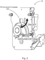
- Fig. 2 shows an example of a first type of actuator 10 that provides a first type of interface that is based on two pins. These pins follow a circular trajectory. One pin drives closing and opening operation and the second one switches between ground and off (opened) positions.
- the shunt vacuum interrupter or shunt module 30 is attached to the pin, which switches between opened and closed. This pin is labelled as pin 120 in the discussion below.
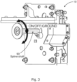
- Fig. 3 shows an example of a second type of actuator 10 that provides a second type of interface is based on a spline shaft.
- This shaft has three angular positions - on, off and ground or, in other terms, opened, closed and ground.
- the shunt vacuum interrupter module or shunt module 30 is placed on or attached to the spline shaft between the wall of the gas-insulated tank and the drive.
- This spline shaft is labelled as shaft 90 in the discussion below.
- a pin can be located to rotate in an arc.
- Such a pin can also be the pin 120 in the discussion below.
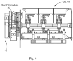
- Fig. 4 shows a schematic representation of an exemplar switch system having an actuator 10 as shown in Fig. 2 , where the shunt module 30 sits at the interface between the actuator 10 and the switch 20 that can be associated with one or more vacuum interrupters 40.
- the shunt module is coupled to the pin 120 of the actuator 10 as discussed above.
- Fig. 5 shows a schematic representation of an exemplar switch system having an actuator 10 as shown in Fig. 3 , where the shunt module 30 sits at the interface between the actuator 10 and the switch 20 that can be associated with one or more vacuum interrupters 40.
- the shunt module 30 can be coupled to the shaft 90 of the actuator 10 as discussed above. However, as discussed above as the shaft 90 rotates a pin 120 can be made to move in an arc, and the shunt module can be coupled to the pin 120.
- the shunt module 30 is configured to apply a driving force to the switch 20 as the switch transitions from the second position to the first position.
- a decelerating closing movement of the switch 20 can be provided and also an accelerating opening movement.
- the opening movement can be approximately 20% slower than the opening movement.
- the shunt module 30 comprises a spring 50.
- the shunt module comprises at least one part 60, 70, 80 configured to move as the switch 20 transitions from the first position to the second position. As the at least one part of the shunt module moves as the switch transitions from the first position to the second position the shunt module is configured such that the spring is compressed.
- the at least one part 60, 70, 80 of the shunt module 30 is configured to move as the switch 20 transitions from the second position to the first position. As the at least one part of the shunt module moves as the switch transitions from the second position to the first position the shunt module is configured such that the spring expands.
- the at least one part of the shunt module 30 comprises a first arm or lever 60 fixedly connected at one end to a shaft 90 that rotates in a first direction as the actuator 10 transitions the switch 20 from the first position to the second position.
- a second end of the first arm or lever is rotationally connected to a first end of a second arm or lever 70 at a rotation connection 100.
- a second end of the second arm or lever is coupled to the shunt module or actuator or switch at a coupling location 110.
- the spring 50 is located between the rotation connection and the coupling location, and as the shaft rotates in the first direction a distance between the rotation connection and the coupling location is reduced.
- the shaft rotates in a second direction opposite to the first direction as the actuator transitions the switch from the second position to the first position the distance between the rotation connection and the coupling location is increased.
- Figs. 6 and 7 show schematic representations of exemplar shunt modules 30 for operation with an actuator 10 as shown in Fig. 3 , that is consistent with this operation.
- the hole for the spline shaft indicates the location of the shaft 90 of the actuator.
- the compressing lever is the first arm or lever 60 described above.
- the spring guiding link is the second arm or lever 70 described above.
- the compression spring is the spring 50 described above.
- the rotational fixation is the coupling location 110 as described above, that is a fixed location and could be of the shunt module 30 or actuator 10 or switch 20, as long as it does not move. It could even be a part of the compartment of the switchgear.
- the second arm or lever has a slot within which the connection between the two arms or levers can slide or within which the coupling location can slide, and the spring 50 is located between these locations and is compressed as the actuator 10 operates to close the switch 20.
- the first arm or lever 60 could have the slot and the spring 50 could be located along the first arm or lever and also be compressed as the actuator 10 operates to close the switch 20. This compression of the spring 50 provides a retarding or decelerating force.
- Figs. 8 , 9 , and 10 then show schematic representations of an exemplar shunt module 20 for operation with such an actuator 10, with Fig. 8 showing a closed position for an associated switch, Fig. 9 showing an open position for an associated switch and Fig. 10 showing a ground position.
- the shunt VI module of shunt module 30 is utilizes a compression spring 50.
- This spring is being compressed during opening and thus the energy accumulates in the spring and thus the system is slowed down.
- the opposite scenario is applied during closing when the spring is being released and its energy accelerates the closing operation.
- the spline shaft or shaft 90 of the load break switch or actuator 10 can rotate around 90° for each operation, or other angles.
- the shunt module's 30 mechanism is designed to be independent of the angle.
- the system can be configured such that the opened position stays as depictured.
- the compressing lever of SVIM is connected to the drive shaft.
- the compressing pin is fixed to this lever and serves as an element that compresses the spring during opening or is pushed during closing.
- the spring guiding link guides the compression spring.
- the link is fixed by a rotational joint to the drive or switchgear housing.
- the spring end, which does not move, can rest against the rotational joint or against an edge made on the spring guiding link.
- the compression spring can be guided in many ways, as shown
- the at least one part of the shunt module 30 comprises an arm or lever 80 connected at one end at a rotation connection to a pin 120 that moves through an arc in a first direction as the actuator 10 transitions the switch 20 from the first position to the second position.
- a second end of the arm or lever is coupled to the shunt module or actuator or switch at a coupling location 130.
- the spring 50 is located between the rotation connection and the coupling location, and as the pin moves through the arc in the first direction a distance between the rotation connection and the coupling location is reduced.
- the pin moves through an arc in a second direction opposite to the first direction as the actuator transitions the switch from the second position to the first position the distance between the rotation connection and the coupling location is increased.
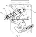
- Figs. 11 , 12 , and 13 show schematic representations of an exemplar shunt module 30 for operation with an actuator 10 as shown in Fig. 2 or 3 , that is consistent with this operation.
- Fig. 11 shows a closed position for an associated switch 20
- Fig. 12 shows an open position for an associated switch
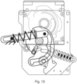
- Fig. 13 shows a ground position.
- the pin 120 can be the opening/closing pin described with respect to Fig. 2 , or could be a pin 120 off centre from the shaft as discussed with respect to Fig. 3 .
- the lever or arm 80 has a slot coupled to a coupling location 130 that is at a fixed position that can be of the actuator, the shunt module or the switch or even of the switchgear compartment, and in moving from closed to pen positions the spring is compressed.
- the shunt module 30 comprises a spring 50 connected at one end to a pin 120 that moves through an arc in a first direction as the actuator 10 transitions the switch 20 from the first position to the second position.
- a second end of the spring is connected to the shunt module or actuator or switch at a fixed location 140, and as the pin moves through the arc in the first direction the spring is put under tension.
- the pin moves through an arc in a second direction opposite to the first direction as the actuator transitions the switch from the second position to the first position the distance between the rotation connection and the spring contracts.
- Figs. 14 , 15 , and 16 show schematic representations of an exemplar shunt module 30 for operation with an actuator 10 as shown in Fig. 2 or 3 , that is consistent with this operation.
- Fig. 14 shows a closed position for an associated switch 20
- Fig. 15 shows an open position for the associated switch 20
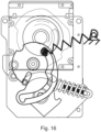
- Fig. 16 shows a ground position.
- the pin 120 can be the opening/closing pin described with respect to Fig. 2 , or could be a pin 120 off centre from the shaft as discussed with respect to Fig. 3 .
- the spring 50 is coupled to a coupling location 140 that is at a fixed position that can be of the actuator, the shunt module or the switch or even of the switchgear compartment, and in moving from closed to pen positions the spring is stretched or put under tension.
- the shunt module 30 comprises an air damper 150.
- the air damper comprises a plunger 160 connected at one end to a pin 120 that moves through an arc in a first direction as the actuator 10 transitions the switch 20 from the first position to the second position.
- the air damper comprises a cylinder 170 within which the plunger can move.
- the cylinder is connected to the shunt module or actuator or switch at a fixed location 180, and as the pin moves through the arc in the first direction the plunger is configured to move within the cylinder in a first direction to compress a gas within the cylinder.
- the cylinder comprises a one way valve 190 and as the pin moves through an arc in a second direction opposite to the first direction as the actuator transitions the switch from the second position to the first position the plunger is configured to move within the cylinder in a second direction opposite to the first direction. As the plunger moves in the cylinder in the second direction the one way valve is configured to let at least some of the gas to pass through the valve.
- Figs. 17 , 18 , and 19 show schematic representations of an exemplar shunt module 30 for operation with an actuator 10 as shown in Fig. 2 or 3 consistent with this example.
- Fig. 17 shows a closed position for an associated switch 20
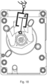
- Fig. 18 shows an open position for the associated switch
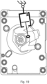
- Fig. 19 shows a ground position.
- the pin 120 can be the opening/closing pin described with respect to Fig. 2 , or could be a pin 120 off centre from the shaft as discussed with respect to Fig. 3 .
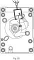
- Figs. 20 , 21 , and 22 show schematic representations of an exemplar shunt module 30 for operation with an actuator 10 as shown in Fig. 2 or 3 consistent with this example.
- Fig. 20 shows a closed position for an associated switch 20
- Fig. 21 shows an open position for the associated switch
- Fig. 22 shows a ground position.
- the pin 120 can be the opening/closing pin described with respect to Fig. 2 , or could be a pin 120 off centre from the shaft as discussed with respect to Fig. 3 .
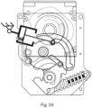
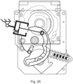
- Figs. 23 , 24 , and 25 show schematic representations of an exemplar shunt module 30 for operation with an actuator 10 as shown in Fig. 2 or 3 consistent with this example.
- Fig. 23 shows a closed position for an associated switch 20
- Fig. 24 shows an open position for the associated switch
- Fig. 25 shows a ground position.
- the pin 120 can be the opening/closing pin described with respect to Fig. 2 , or could be a pin 120 off centre from the shaft as discussed with respect to Fig. 3 .
- Figs. 26 , 27 , and 28 show schematic representations of an exemplar shunt module 30 for operation with an actuator 10 as shown in Fig. 2 or 3 consistent with this example.
- Fig. 26 shows a closed position for an associated switch 20
- Fig. 27 shows an open position for the associated switch
- Fig. 28 shows a ground position.
- the pin 120 can be the opening/closing pin described with respect to Fig. 2 , or could be a pin 120 off centre from the shaft as discussed with respect to Fig. 3 .
- the cylinder 170 can have a one way valve 190 that lets gas pass through it, such that in moving from the opened to the closed positions there is no retarding force.
- the plunger 160 that moves in the cylinder 170 can have a one way valve 190 that lets gas pass through it, such that in moving from the opened to the closed positions there is no retarding force.
- one end of the plunger is connected to a part of the actuator - pin 120 - that moves through an arc and the cylinder 170 is connected to a fixed location 180.
- An exemplar vacuum interrupter system comprises:
- the actuator is configured to transition the switch from a first position to a second position.
- the actuator is configured to transition the switch from the second position to the first position.
- the switch in transitioning from the first position to the second position is configured to open the vacuum interrupter.
- the shunt module is configured to apply a retarding force to the switch as the switch transitions from the first position to the second position.
- the shunt module is configured to apply a driving force to the switch as the switch transitions from the second position to the first position.
- the shunt module comprises a spring 50.
- the shunt module comprises at least one part 60, 70, 80 configured to move as the switch transitions from the first position to the second position. As the at least one part of the shunt module moves as the switch transitions from the first position to the second position the shunt module is configured such that the spring is compressed.
- the at least one part 60, 70, 80 of the shunt module is configured to move as the switch transitions from the second position to the first position. As the at least one part of the shunt module moves as the switch transitions from the second position to the first position the shunt module is configured such that the spring expands.
- the at least one part of the shunt module comprises a first arm or lever 60 fixedly connected at one end to a shaft 90 that rotates in a first direction as the actuator transitions the switch from the first position to the second position.
- a second end of a the first arm or lever is rotationally connected to a first end of a second arm or lever 70 at a rotation connection 100.
- a second end of the second arm or lever is coupled to the shunt module or actuator or switch at a coupling location 110.
- the spring is located between the rotation connection and the coupling location, and wherein as the shaft rotates in the first direction a distance between the rotation connection and the coupling location is reduced.
- the at least one part of the shunt module comprises an arm or lever 80 connected at one end at a rotation connection to a pin 120 that moves through an arc in a first direction as the actuator transitions the switch from the first position to the second position.
- a second end of the arm or lever is coupled to the shunt module or actuator or switch at a coupling location 130.
- the spring is located between the rotation connection and the coupling location, and as the pin moves through the arc in the first direction a distance between the rotation connection and the coupling location is reduced.
- the pin moves through an arc in a second direction opposite to the first direction as the actuator transitions the switch from the second position to the first position the distance between the rotation connection and the coupling location is increased.
- the shunt module comprises a spring 50 connected at one end to a pin 120 that moves through an arc in a first direction as the actuator transitions the switch from the first position to the second position.
- a second end of the spring is connected to the shunt module or actuator or switch at a fixed location 140, and as the pin moves through the arc in the first direction the spring is put under tension.
- the shunt module comprises an air damper 150.
- the air damper comprises a plunger 160 connected at one end to a pin 120 that moves through an arc in a first direction as the actuator transitions the switch from the first position to the second position.
- the air damper comprises a cylinder 170 within which the plunger can move.
- the cylinder is connected to the shunt module or actuator or switch at a fixed location 180. As the pin moves through the arc in the first direction the plunger is configured to move within the cylinder in a first direction to compress a gas within the cylinder.
- the cylinder comprises a one way valve 190, and as the pin moves through an arc in a second direction opposite to the first direction as the actuator transitions the switch from the second position to the first position the plunger is configured to move within the cylinder in a second direction opposite to the first direction.
- the one way valve is configured to let at least some of the gas to pass through the valve.
- a low or medium or high voltage switchgear can comprise a switch system as described above and/or can comprise a vacuum interrupter system as described above.
Landscapes
- Driving Mechanisms And Operating Circuits Of Arc-Extinguishing High-Tension Switches (AREA)
Abstract
- an actuator (10);
- a switch (20); and
- a shunt module (30);
wherein the actuator is configured to transition the switch from a first position to a second position;
wherein the actuator is configured to transition the switch from the second position to the first position;
wherein the switch in transitioning from the first position to the second position is configured to open a vacuum interrupter (40); and
wherein the shunt module is configured to apply a retarding force to the switch as the switch transitions from the first position to the second position.
Description
- The present invention relates to a switch system for a vacuum interrupter, a vacuum interrupter system, and a low, medium or high voltage switchgear.
- Gas insulated switchgears (GIS) are subject to sustainability requirements, meaning that the overall product needs to be changed towards incorporating sustainable products. Sulphur hexafluoride (SF6), used as the gases dielectric medium in GIS, is one of the most potent greenhouse gases, and thus it must be replaced by more sustainable alternative, for example dry air. However, this change poses challenges for load break switches (LBS), because the sustainable alternatives to SF6 have lower dielectric strength, which complicates the breaking of the electrical arc during the opening of the LBS.
- One solution breaking the electrical arc during the opening of LBS is the implementation of a shunt vacuum interrupter (SVI), which uses a smaller vacuum interrupter to extinguish the arc during opening of the vacuum interrupter. During closing of the vacuum interrupter, the respective electrical arc making of the switch SVI is not engaged. This is the requirement for two different speeds of LBS. During opening or breaking, the SVI needs enough time to assure that the arc extinction takes place in the SVI and thus, the opening operation must be slow. However, the closing operation needs to be carried out as fast as possible to reduce the duration of electrical arcing. Therefore, LBS with SVI must be actuated so that the opening operation is significantly slower than the closing operation.
- Standard LBS drives designed to release the same energy during closing and opening operations, and modifying such a drive to release significantly higher energy during closing than opening is very complex.
- There is a need to address these issues.
- Therefore, it would be advantageous to have an improved switch system for a vacuum interrupter.
- The object of the present invention is solved with the subject matter of the independent claims, wherein further embodiments are incorporated in the dependent claims.
- In a first aspect, there is provided a switch system for a vacuum interrupter, comprising:
- an actuator;
- a switch; and
- a shunt module
- The actuator is configured to transition the switch from a first position to a second position. The actuator is configured to transition the switch from the second position to the first position. The switch in transitioning from the first position to the second position is configured to open a vacuum interrupter. The shunt module is configured to apply a retarding force to the switch as the switch transitions from the first position to the second position.
- In an example, the shunt module is configured to apply a driving force to the switch as the switch transitions from the second position to the first position.
- In an example, the shunt module comprises a spring. The shunt module comprises at least one part configured to move as the switch transitions from the first position to the second position. As the at least one part of the shunt module moves as the switch transitions from the first position to the second position the shunt module is configured such that the spring is compressed.
- In an example, the at least one part of the shunt module is configured to move as the switch transitions from the second position to the first position. As the at least one part of the shunt module moves as the switch transitions from the second position to the first position the shunt module is configured such that the spring expands.
- In an example, the at least one part of the shunt module comprises a first arm or lever fixedly connected at one end to a shaft that rotates in a first direction as the actuator transitions the switch from the first position to the second position. A second end of the first arm or lever is rotationally connected to a first end of a second arm or lever at a rotation connection. A second end of the second arm or lever is coupled to the shunt module or actuator or switch at a coupling location. The spring is located between the rotation connection and the coupling location, and as the shaft rotates in the first direction a distance between the rotation connection and the coupling location is reduced.
- In an example, as the shaft rotates in a second direction opposite to the first direction as the actuator transitions the switch from the second position to the first position the distance between the rotation connection and the coupling location is increased.
- In an example, the at least one part of the shunt module comprises an arm or lever connected at one end at a rotation connection to a pin that moves through an arc in a first direction as the actuator transitions the switch from the first position to the second position. A second end of the arm or lever is coupled to the shunt module or actuator or switch at a coupling location. The spring is located between the rotation connection and the coupling location, and as the pin moves through the arc in the first direction a distance between the rotation connection and the coupling location is reduced.
- In an example, as the pin moves through an arc in a second direction opposite to the first direction as the actuator transitions the switch from the second position to the first position the distance between the rotation connection and the coupling location is increased.
- In an example, the shunt module comprises a spring connected at one end to a pin that moves through an arc in a first direction as the actuator transitions the switch from the first position to the second position. A second end of the spring is connected to the shunt module or actuator or switch at a fixed location, and as the pin moves through the arc in the first direction the spring is put under tension.
- In an example, as the pin moves through an arc in a second direction opposite to the first direction as the actuator transitions the switch from the second position to the first position the distance between the rotation connection and the spring contracts.
- In an example, the shunt module comprises an air damper.
- In an example, the air damper comprises a plunger connected at one end to a pin that moves through an arc in a first direction as the actuator transitions the switch from the first position to the second position. The air damper comprises a cylinder within which the plunger can move, and the cylinder is connected to the shunt module or actuator or switch at a fixed location. As the pin moves through the arc in the first direction the plunger is configured to move within the cylinder in a first direction to compress a gas within the cylinder.
- In an example, the cylinder comprises a one way valve. As the pin moves through an arc in a second direction opposite to the first direction as the actuator transitions the switch from the second position to the first position the plunger is configured to move within the cylinder in a second direction opposite to the first direction. As the plunger moves in the cylinder in the second direction the one way valve is configured to let at least some of the gas to pass through the valve.
- In second aspect, there is provided a vacuum interrupter system, comprising:
- an actuator;
- a switch;
- a shunt module; and
- a vacuum interrupter.
- The actuator is configured to transition the switch from a first position to a second position. The actuator is configured to transition the switch from the second position to the first position. The switch in transitioning from the first position to the second position is configured to open the vacuum interrupter. The shunt module is configured to apply a retarding force to the switch as the switch transitions from the first position to the second position.
- In a third aspect there is provided a low or medium or high voltage switchgear comprising a switch system according to the first aspect and/or a vacuum interrupter system according to the second aspect.
- The above aspects and examples will become apparent from and be elucidated with reference to the embodiments described hereinafter.
- Exemplary embodiments will be described in the following with reference to the following drawings:
-
Fig. 1 shows a schematic representation of an exemplar switch system; -
Fig. 2 shows a schematic representation of an exemplar actuator; -
Fig. 3 shows a schematic representation of an exemplar actuator; -
Fig. 4 shows a schematic representation of an exemplar switch system having an actuator as shown inFig. 2 ; -
Fig. 5 shows a schematic representation of an exemplar switch system having an actuator as shown inFig. 3 ; -
Fig. 6 shows a schematic representation of an exemplar shunt module for operation with an actuator as shown inFig. 3 ; -
Fig. 7 shows a schematic representation of an exemplar shunt module for operation with an actuator as shown inFig. 3 ; -
Figs. 8 ,9 , and10 show schematic representations of an exemplar shunt module for operation with an actuator as shown inFig. 3 , withFig. 8 showing a closed position for an associated switch,Fig. 9 showing an open position for an associated switch andFig. 10 showing a ground position; -
Figs. 11 ,12 , and13 show schematic representations of an exemplar shunt module for operation with an actuator as shown inFig. 2 or3 , withFig. 11 showing a closed position for an associated switch,Fig. 12 showing an open position for an associated switch andFig. 13 showing a ground position; -
Figs. 14 ,15 , and16 show schematic representations of an exemplar shunt module for operation with an actuator as shown inFig. 2 or3 , withFig. 14 showing a closed position for an associated switch,Fig. 15 showing an open position for an associated switch andFig. 16 showing a ground position; -
Figs. 17 ,18 , and19 show schematic representations of an exemplar shunt module for operation with an actuator as shown inFig. 2 or3 , withFig. 17 showing a closed position for an associated switch,Fig. 18 showing an open position for an associated switch andFig. 19 showing a ground position; -
Figs. 20 ,21 , and22 show schematic representations of an exemplar shunt module for operation with an actuator as shown inFig. 2 or3 , withFig. 20 showing a closed position for an associated switch,Fig. 21 showing an open position for an associated switch andFig. 22 showing a ground position; -
Figs. 23 ,24 , and25 show schematic representations of an exemplar shunt module for operation with an actuator as shown inFig. 2 or3 , withFig. 23 showing a closed position for an associated switch,Fig. 24 showing an open position for an associated switch andFig. 25 showing a ground position; and -
Figs. 26 ,27 , and28 show schematic representations of an exemplar shunt module for operation with an actuator as shown inFig. 2 or3 , withFig. 26 showing a closed position for an associated switch,Fig. 27 showing an open position for an associated switch andFig. 28 showing a ground position. -
Figs. 1-28 relate to a switch system for a vacuum interrupter and a vacuum interrupter system, either or both of which can be utilized with a low, medium or high voltage switchgear. - An exemplar switch system for a vacuum interrupter comprises:
- an
actuator 10; - a
switch 20; and - a
shunt module 30. - The actuator is configured to transition the switch from a first position to a second position. The actuator is configured to transition the switch from the second position to the first position. The switch in transitioning from the first position to the second position is configured to open a vacuum interrupter 40. The shunt module is configured to apply a retarding force to the switch as the switch transitions from the first position to the second position.
- Looking at
Fig. 1 a gas insulated tank or compartment of a switch gear is shown. A switch or switchingsystem 20 is inside the compartment and theswitch 20 can have an associated one or more vacuum interrupters 40. Anactuator 10 sits outside the compartment and at an interface between the actuator and switch, ashunt module 30 can be located. - Examples of the new shunt module are configured to operate with two different types of actuator, and in effect is consistent with the interface as shown in
Fig. 1 . - There are in effect two basic types of interfaces between the switching mechanism or switch 20 and the drive or
actuator 10. This interface is out of the gas-insulated tank. -
Fig. 2 shows an example of a first type ofactuator 10 that provides a first type of interface that is based on two pins. These pins follow a circular trajectory. One pin drives closing and opening operation and the second one switches between ground and off (opened) positions. The shunt vacuum interrupter orshunt module 30 is attached to the pin, which switches between opened and closed. This pin is labelled aspin 120 in the discussion below. -
Fig. 3 shows an example of a second type ofactuator 10 that provides a second type of interface is based on a spline shaft. This shaft has three angular positions - on, off and ground or, in other terms, opened, closed and ground. The shunt vacuum interrupter module orshunt module 30 is placed on or attached to the spline shaft between the wall of the gas-insulated tank and the drive. This spline shaft is labelled asshaft 90 in the discussion below. - Looking at
Fig. 3 it is clear that as the spline shaft rotates, other parts can be made to rotate in a arc about the spline shaft, and a pin can be located to rotate in an arc. Such a pin can also be thepin 120 in the discussion below. -
Fig. 4 shows a schematic representation of an exemplar switch system having an actuator 10 as shown inFig. 2 , where theshunt module 30 sits at the interface between the actuator 10 and theswitch 20 that can be associated with one or more vacuum interrupters 40. The shunt module is coupled to thepin 120 of theactuator 10 as discussed above. -
Fig. 5 shows a schematic representation of an exemplar switch system having an actuator 10 as shown inFig. 3 , where theshunt module 30 sits at the interface between the actuator 10 and theswitch 20 that can be associated with one or more vacuum interrupters 40. Theshunt module 30 can be coupled to theshaft 90 of theactuator 10 as discussed above. However, as discussed above as theshaft 90 rotates apin 120 can be made to move in an arc, and the shunt module can be coupled to thepin 120. - According to an example, the
shunt module 30 is configured to apply a driving force to theswitch 20 as the switch transitions from the second position to the first position. - Thus a decelerating closing movement of the
switch 20 can be provided and also an accelerating opening movement. For example, the opening movement can be approximately 20% slower than the opening movement. - According to an example, the
shunt module 30 comprises aspring 50. The shunt module comprises at least onepart switch 20 transitions from the first position to the second position. As the at least one part of the shunt module moves as the switch transitions from the first position to the second position the shunt module is configured such that the spring is compressed. - According to an example, the at least one
part shunt module 30 is configured to move as theswitch 20 transitions from the second position to the first position. As the at least one part of the shunt module moves as the switch transitions from the second position to the first position the shunt module is configured such that the spring expands. - According to an example, the at least one part of the
shunt module 30 comprises a first arm orlever 60 fixedly connected at one end to ashaft 90 that rotates in a first direction as the actuator 10 transitions theswitch 20 from the first position to the second position. A second end of the first arm or lever is rotationally connected to a first end of a second arm orlever 70 at arotation connection 100. A second end of the second arm or lever is coupled to the shunt module or actuator or switch at acoupling location 110. Thespring 50 is located between the rotation connection and the coupling location, and as the shaft rotates in the first direction a distance between the rotation connection and the coupling location is reduced. - According to an example, as the shaft rotates in a second direction opposite to the first direction as the actuator transitions the switch from the second position to the first position the distance between the rotation connection and the coupling location is increased.
-
Figs. 6 and7 show schematic representations ofexemplar shunt modules 30 for operation with anactuator 10 as shown inFig. 3 , that is consistent with this operation. The hole for the spline shaft indicates the location of theshaft 90 of the actuator. The compressing lever is the first arm orlever 60 described above. The spring guiding link is the second arm orlever 70 described above. The compression spring is thespring 50 described above. In both cases the first and second arms or levers are rotationally connected to each other. The rotational fixation is thecoupling location 110 as described above, that is a fixed location and could be of theshunt module 30 oractuator 10 orswitch 20, as long as it does not move. It could even be a part of the compartment of the switchgear. The second arm or lever has a slot within which the connection between the two arms or levers can slide or within which the coupling location can slide, and thespring 50 is located between these locations and is compressed as theactuator 10 operates to close theswitch 20. It is also clear that the first arm orlever 60 could have the slot and thespring 50 could be located along the first arm or lever and also be compressed as theactuator 10 operates to close theswitch 20. This compression of thespring 50 provides a retarding or decelerating force. -
Figs. 8 ,9 , and10 then show schematic representations of anexemplar shunt module 20 for operation with such anactuator 10, withFig. 8 showing a closed position for an associated switch,Fig. 9 showing an open position for an associated switch andFig. 10 showing a ground position. - Thus, the shunt VI module of
shunt module 30 is utilizes acompression spring 50. This spring is being compressed during opening and thus the energy accumulates in the spring and thus the system is slowed down. The opposite scenario is applied during closing when the spring is being released and its energy accelerates the closing operation. - The spline shaft or
shaft 90 of the load break switch oractuator 10 can rotate around 90° for each operation, or other angles. The shunt module's 30 mechanism is designed to be independent of the angle. The system can be configured such that the opened position stays as depictured. - The compressing lever of SVIM is connected to the drive shaft. The compressing pin is fixed to this lever and serves as an element that compresses the spring during opening or is pushed during closing. The spring guiding link guides the compression spring. The link is fixed by a rotational joint to the drive or switchgear housing. The spring end, which does not move, can rest against the rotational joint or against an edge made on the spring guiding link. The compression spring can be guided in many ways, as shown
According to an example, the at least one part of theshunt module 30 comprises an arm orlever 80 connected at one end at a rotation connection to apin 120 that moves through an arc in a first direction as the actuator 10 transitions theswitch 20 from the first position to the second position. A second end of the arm or lever is coupled to the shunt module or actuator or switch at acoupling location 130. Thespring 50 is located between the rotation connection and the coupling location, and as the pin moves through the arc in the first direction a distance between the rotation connection and the coupling location is reduced. - According to an example, as the pin moves through an arc in a second direction opposite to the first direction as the actuator transitions the switch from the second position to the first position the distance between the rotation connection and the coupling location is increased.
-
Figs. 11 ,12 , and13 show schematic representations of anexemplar shunt module 30 for operation with anactuator 10 as shown inFig. 2 or3 , that is consistent with this operation.Fig. 11 shows a closed position for an associatedswitch 20,Fig. 12 shows an open position for an associated switch andFig. 13 shows a ground position. Thepin 120 can be the opening/closing pin described with respect toFig. 2 , or could be apin 120 off centre from the shaft as discussed with respect toFig. 3 . the lever orarm 80 has a slot coupled to acoupling location 130 that is at a fixed position that can be of the actuator, the shunt module or the switch or even of the switchgear compartment, and in moving from closed to pen positions the spring is compressed. - According to an example, the
shunt module 30 comprises aspring 50 connected at one end to apin 120 that moves through an arc in a first direction as the actuator 10 transitions theswitch 20 from the first position to the second position. A second end of the spring is connected to the shunt module or actuator or switch at a fixedlocation 140, and as the pin moves through the arc in the first direction the spring is put under tension. - According to an example, as the pin moves through an arc in a second direction opposite to the first direction as the actuator transitions the switch from the second position to the first position the distance between the rotation connection and the spring contracts.
-
Figs. 14 ,15 , and16 show schematic representations of anexemplar shunt module 30 for operation with anactuator 10 as shown inFig. 2 or3 , that is consistent with this operation.Fig. 14 shows a closed position for an associatedswitch 20,Fig. 15 shows an open position for the associatedswitch 20 andFig. 16 shows a ground position. Thepin 120 can be the opening/closing pin described with respect toFig. 2 , or could be apin 120 off centre from the shaft as discussed with respect toFig. 3 . Thespring 50 is coupled to acoupling location 140 that is at a fixed position that can be of the actuator, the shunt module or the switch or even of the switchgear compartment, and in moving from closed to pen positions the spring is stretched or put under tension. - According to an example, the
shunt module 30 comprises anair damper 150. - According to an example, the air damper comprises a
plunger 160 connected at one end to apin 120 that moves through an arc in a first direction as the actuator 10 transitions theswitch 20 from the first position to the second position. The air damper comprises acylinder 170 within which the plunger can move. The cylinder is connected to the shunt module or actuator or switch at a fixedlocation 180, and as the pin moves through the arc in the first direction the plunger is configured to move within the cylinder in a first direction to compress a gas within the cylinder. - According to an example, the cylinder comprises a one
way valve 190 and as the pin moves through an arc in a second direction opposite to the first direction as the actuator transitions the switch from the second position to the first position the plunger is configured to move within the cylinder in a second direction opposite to the first direction. As the plunger moves in the cylinder in the second direction the one way valve is configured to let at least some of the gas to pass through the valve. -
Figs. 17 ,18 , and19 show schematic representations of anexemplar shunt module 30 for operation with anactuator 10 as shown inFig. 2 or3 consistent with this example.Fig. 17 shows a closed position for an associatedswitch 20,Fig. 18 shows an open position for the associated switch andFig. 19 shows a ground position. Thepin 120 can be the opening/closing pin described with respect toFig. 2 , or could be apin 120 off centre from the shaft as discussed with respect toFig. 3 . -
Figs. 20 ,21 , and22 show schematic representations of anexemplar shunt module 30 for operation with anactuator 10 as shown inFig. 2 or3 consistent with this example.Fig. 20 shows a closed position for an associatedswitch 20,Fig. 21 shows an open position for the associated switch andFig. 22 shows a ground position. Thepin 120 can be the opening/closing pin described with respect toFig. 2 , or could be apin 120 off centre from the shaft as discussed with respect toFig. 3 . -
Figs. 23 ,24 , and25 show schematic representations of anexemplar shunt module 30 for operation with anactuator 10 as shown inFig. 2 or3 consistent with this example.Fig. 23 shows a closed position for an associatedswitch 20,Fig. 24 shows an open position for the associated switch andFig. 25 shows a ground position. Thepin 120 can be the opening/closing pin described with respect toFig. 2 , or could be apin 120 off centre from the shaft as discussed with respect toFig. 3 . -
Figs. 26 ,27 , and28 show schematic representations of anexemplar shunt module 30 for operation with anactuator 10 as shown inFig. 2 or3 consistent with this example.Fig. 26 shows a closed position for an associatedswitch 20,Fig. 27 shows an open position for the associated switch andFig. 28 shows a ground position. Thepin 120 can be the opening/closing pin described with respect toFig. 2 , or could be apin 120 off centre from the shaft as discussed with respect toFig. 3 . - As shown in
Figs. 17-19 and23-25 , thecylinder 170 can have a oneway valve 190 that lets gas pass through it, such that in moving from the opened to the closed positions there is no retarding force. - As shown in
Figs. 20-22 and26-28 , theplunger 160 that moves in thecylinder 170 can have a oneway valve 190 that lets gas pass through it, such that in moving from the opened to the closed positions there is no retarding force. - In all cases, one end of the plunger is connected to a part of the actuator - pin 120 - that moves through an arc and the
cylinder 170 is connected to a fixedlocation 180. - An exemplar vacuum interrupter system comprises:
- an
actuator 10; - a
switch 20; - a
shunt module 30; and - a vacuum interrupter 40.
- The actuator is configured to transition the switch from a first position to a second position. The actuator is configured to transition the switch from the second position to the first position. The switch in transitioning from the first position to the second position is configured to open the vacuum interrupter. The shunt module is configured to apply a retarding force to the switch as the switch transitions from the first position to the second position.
- In an example, the shunt module is configured to apply a driving force to the switch as the switch transitions from the second position to the first position.
- In an example, the shunt module comprises a
spring 50. The shunt module comprises at least onepart - In an example, the at least one
part - In an example, the at least one part of the shunt module comprises a first arm or
lever 60 fixedly connected at one end to ashaft 90 that rotates in a first direction as the actuator transitions the switch from the first position to the second position. A second end of a the first arm or lever is rotationally connected to a first end of a second arm orlever 70 at arotation connection 100. A second end of the second arm or lever is coupled to the shunt module or actuator or switch at acoupling location 110. The spring is located between the rotation connection and the coupling location, and wherein as the shaft rotates in the first direction a distance between the rotation connection and the coupling location is reduced. - In an example, as the shaft rotates in a second direction opposite to the first direction as the actuator transitions the switch from the second position to the first position the distance between the rotation connection and the coupling location is increased.
- In an example, the at least one part of the shunt module comprises an arm or
lever 80 connected at one end at a rotation connection to apin 120 that moves through an arc in a first direction as the actuator transitions the switch from the first position to the second position. A second end of the arm or lever is coupled to the shunt module or actuator or switch at acoupling location 130. The spring is located between the rotation connection and the coupling location, and as the pin moves through the arc in the first direction a distance between the rotation connection and the coupling location is reduced. - In an example, as the pin moves through an arc in a second direction opposite to the first direction as the actuator transitions the switch from the second position to the first position the distance between the rotation connection and the coupling location is increased.
- In an example, the shunt module comprises a
spring 50 connected at one end to apin 120 that moves through an arc in a first direction as the actuator transitions the switch from the first position to the second position. A second end of the spring is connected to the shunt module or actuator or switch at a fixedlocation 140, and as the pin moves through the arc in the first direction the spring is put under tension. - In an example, as the pin moves through an arc in a second direction opposite to the first direction as the actuator transitions the switch from the second position to the first position the distance between the rotation connection and the spring contracts.
- In an example, the shunt module comprises an
air damper 150. - In an example, the air damper comprises a
plunger 160 connected at one end to apin 120 that moves through an arc in a first direction as the actuator transitions the switch from the first position to the second position. The air damper comprises acylinder 170 within which the plunger can move. The cylinder is connected to the shunt module or actuator or switch at a fixedlocation 180. As the pin moves through the arc in the first direction the plunger is configured to move within the cylinder in a first direction to compress a gas within the cylinder. - In an example, the cylinder comprises a one
way valve 190, and as the pin moves through an arc in a second direction opposite to the first direction as the actuator transitions the switch from the second position to the first position the plunger is configured to move within the cylinder in a second direction opposite to the first direction. When the plunger moves in the second direction the one way valve is configured to let at least some of the gas to pass through the valve. - A low or medium or high voltage switchgear can comprise a switch system as described above and/or can comprise a vacuum interrupter system as described above.
Claims (15)
- A switch system for a vacuum interrupter, comprising:- an actuator (10);- a switch (20); and- a shunt module (30);wherein the actuator is configured to transition the switch from a first position to a second position;wherein the actuator is configured to transition the switch from the second position to the first position;wherein the switch in transitioning from the first position to the second position is configured to open a vacuum interrupter (40); andwherein the shunt module is configured to apply a retarding force to the switch as the switch transitions from the first position to the second position.
- Switch system according to claim 1, wherein the shunt module is configured to apply a driving force to the switch as the switch transitions from the second position to the first position.
- Switch system according to any of claims 1-2, wherein the shunt module comprises a spring (50), wherein the shunt module comprises at least one part (60, 70, 80) configured to move as the switch transitions from the first position to the second position, and wherein as the at least one part of the shunt module moves as the switch transitions from the first position to the second position the shunt module is configured such that the spring is compressed.
- Switch system according to claim 3, wherein the at least one part (60, 70, 80) of the shunt module is configured to move as the switch transitions from the second position to the first position, and wherein as the at least one part of the shunt module moves as the switch transitions from the second position to the first position the shunt module is configured such that the spring expands.
- Switch system according to any of claims 3-4, wherein the at least one part of the shunt module comprises a first arm or lever (60) fixedly connected at one end to a shaft (90) that rotates in a first direction as the actuator transitions the switch from the first position to the second position, wherein a second end of the first arm or lever is rotationally connected to a first end of a second arm or lever (70) at a rotation connection (100), wherein a second end of the second arm or lever is coupled to the shunt module or actuator or switch at a coupling location (110), wherein the spring is located between the rotation connection and the coupling location, and wherein as the shaft rotates in the first direction a distance between the rotation connection and the coupling location is reduced.
- Switch system according to claim 5, wherein as the shaft rotates in a second direction opposite to the first direction as the actuator transitions the switch from the second position to the first position the distance between the rotation connection and the coupling location is increased.
- Switch system according to any of claims 3-4, wherein the at least one part of the shunt module comprises an arm or lever (80) connected at one end at a rotation connection to a pin (120) that moves through an arc in a first direction as the actuator transitions the switch from the first position to the second position, wherein a second end of the arm or lever is coupled to the shunt module or actuator or switch at a coupling location (130), wherein the spring is located between the rotation connection and the coupling location, and wherein as the pin moves through the arc in the first direction a distance between the rotation connection and the coupling location is reduced.
- Switch system according to claim 7, wherein as the pin moves through an arc in a second direction opposite to the first direction as the actuator transitions the switch from the second position to the first position the distance between the rotation connection and the coupling location is increased.
- Switch system according to any of claims 1-2, wherein the shunt module comprises a spring (50) connected at one end to a pin (120) that moves through an arc in a first direction as the actuator transitions the switch from the first position to the second position, wherein a second end of the spring is connected to the shunt module or actuator or switch at a fixed location (140), and wherein as the pin moves through the arc in the first direction the spring is put under tension.
- Switch system according to claim 9, wherein as the pin moves through an arc in a second direction opposite to the first direction as the actuator transitions the switch from the second position to the first position the distance between the rotation connection and the spring contracts.
- Switch system according to claim 1, wherein the shunt module comprises an air damper (150).
- Switch system according to claim 11, wherein the air damper comprises a plunger (160) connected at one end to a pin (120) that moves through an arc in a first direction as the actuator transitions the switch from the first position to the second position, wherein the air damper comprises a cylinder (170) within which the plunger can move, wherein the cylinder is connected to the shunt module or actuator or switch at a fixed location (180), and wherein as the pin moves through the arc in the first direction the plunger is configured to move within the cylinder in a first direction to compress a gas within the cylinder.
- Switch system according to claim 12, wherein the cylinder comprises a one way valve (190), and wherein as the pin moves through an arc in a second direction opposite to the first direction as the actuator transitions the switch from the second position to the first position the plunger is configured to move within the cylinder in a second direction opposite to the first direction, and wherein as the plunger moves in the cylinder in the second direction the one way valve is configured to let at least some of the gas to pass through the valve.
- A vacuum interrupter system, comprising:- an actuator (10);- a switch (20);- a shunt module (30); and- a vacuum interrupter (40);wherein the actuator is configured to transition the switch from a first position to a second position;wherein the actuator is configured to transition the switch from the second position to the first position;wherein the switch in transitioning from the first position to the second position is configured to open the vacuum interrupter; andwherein the shunt module is configured to apply a retarding force to the switch as the switch transitions from the first position to the second position.
- A low or medium or high voltage switchgear comprising a switch system according to any of claims 1-13 and/or a vacuum interrupter system according to claim 14.
Priority Applications (2)
| Application Number | Priority Date | Filing Date | Title |
|---|---|---|---|
| EP23191890.5A EP4510161A1 (en) | 2023-08-17 | 2023-08-17 | Switch system for a vacuum interrupter |
| CN202411128319.2A CN119495528A (en) | 2023-08-17 | 2024-08-16 | Switching systems for vacuum interrupters |
Applications Claiming Priority (1)
| Application Number | Priority Date | Filing Date | Title |
|---|---|---|---|
| EP23191890.5A EP4510161A1 (en) | 2023-08-17 | 2023-08-17 | Switch system for a vacuum interrupter |
Publications (1)
| Publication Number | Publication Date |
|---|---|
| EP4510161A1 true EP4510161A1 (en) | 2025-02-19 |
Family
ID=87695962
Family Applications (1)
| Application Number | Title | Priority Date | Filing Date |
|---|---|---|---|
| EP23191890.5A Pending EP4510161A1 (en) | 2023-08-17 | 2023-08-17 | Switch system for a vacuum interrupter |
Country Status (2)
| Country | Link |
|---|---|
| EP (1) | EP4510161A1 (en) |
| CN (1) | CN119495528A (en) |
Citations (4)
| Publication number | Priority date | Publication date | Assignee | Title |
|---|---|---|---|---|
| EP1367616A1 (en) * | 2002-05-29 | 2003-12-03 | Siemens Aktiengesellschaft | Electrical switching device |
| CN111477492A (en) * | 2020-05-18 | 2020-07-31 | 江苏洛凯电气有限公司 | Load switch three-station mechanism with brake separating tripping function |
| CN111540638A (en) * | 2020-06-04 | 2020-08-14 | 温州隆森电气有限公司 | an operating system |
| CN114203490A (en) * | 2021-12-23 | 2022-03-18 | 湖北德润达智能装备有限公司 | Atmospheric air type ring main unit |
-
2023
- 2023-08-17 EP EP23191890.5A patent/EP4510161A1/en active Pending
-
2024
- 2024-08-16 CN CN202411128319.2A patent/CN119495528A/en active Pending
Patent Citations (4)
| Publication number | Priority date | Publication date | Assignee | Title |
|---|---|---|---|---|
| EP1367616A1 (en) * | 2002-05-29 | 2003-12-03 | Siemens Aktiengesellschaft | Electrical switching device |
| CN111477492A (en) * | 2020-05-18 | 2020-07-31 | 江苏洛凯电气有限公司 | Load switch three-station mechanism with brake separating tripping function |
| CN111540638A (en) * | 2020-06-04 | 2020-08-14 | 温州隆森电气有限公司 | an operating system |
| CN114203490A (en) * | 2021-12-23 | 2022-03-18 | 湖北德润达智能装备有限公司 | Atmospheric air type ring main unit |
Also Published As
| Publication number | Publication date |
|---|---|
| CN119495528A (en) | 2025-02-21 |
Similar Documents
| Publication | Publication Date | Title |
|---|---|---|
| US5239150A (en) | Medium voltage circuit breaker with operating mechanism providing reduced operating energy | |
| US7705262B2 (en) | Alternator disconnector circuit-breaker by a servomotor | |
| CN113035636A (en) | Switchgear and distribution equipment | |
| CN104981887A (en) | Electrical apparatus with dual movement of contacts comprising a return device with two levers | |
| CN106683919A (en) | Operating mechanism and switching apparatus using same | |
| EP2707891A1 (en) | Double-motion gas insulated type circuit breaker | |
| US5859398A (en) | Sequential isolating circuit breaker and actuator | |
| EP3046128B1 (en) | Shunt breaking system | |
| EP4510161A1 (en) | Switch system for a vacuum interrupter | |
| KR101899308B1 (en) | Modular moc driver and interlock assembly for circuit breaker | |
| GB1290386A (en) | ||
| US4061896A (en) | Modular vault-type load break switch | |
| KR100618605B1 (en) | Switchgear of gas insulated breaker | |
| US4342889A (en) | Modular vault-type load break switch | |
| US12609258B2 (en) | Two-electric-pole circuit breaker actuated by a common pyrotechnic device | |
| US20250118510A1 (en) | Medium-voltage vacuum circuit breaker | |
| JP7362006B1 (en) | switchgear | |
| JP7362007B1 (en) | switchgear | |
| GB2643406A (en) | Switching device | |
| CN117393363B (en) | Double-acting high-voltage sulfur hexafluoride circuit breaker transmission device | |
| US20240312751A1 (en) | Electric switching device with improved actuation mechanism | |
| JP2653502B2 (en) | Gas circuit breaker | |
| JP2003217408A (en) | Circuit breaker | |
| CN105845494A (en) | Shunt breaking system | |
| KR20260043229A (en) | An actuator that controls the operation of a processing switch |
Legal Events
| Date | Code | Title | Description |
|---|---|---|---|
| PUAI | Public reference made under article 153(3) epc to a published international application that has entered the european phase |
Free format text: ORIGINAL CODE: 0009012 |
|
| STAA | Information on the status of an ep patent application or granted ep patent |
Free format text: STATUS: THE APPLICATION HAS BEEN PUBLISHED |
|
| AK | Designated contracting states |
Kind code of ref document: A1 Designated state(s): AL AT BE BG CH CY CZ DE DK EE ES FI FR GB GR HR HU IE IS IT LI LT LU LV MC ME MK MT NL NO PL PT RO RS SE SI SK SM TR |
|
| STAA | Information on the status of an ep patent application or granted ep patent |
Free format text: STATUS: REQUEST FOR EXAMINATION WAS MADE |
|
| 17P | Request for examination filed |
Effective date: 20250724 |
|
| GRAP | Despatch of communication of intention to grant a patent |
Free format text: ORIGINAL CODE: EPIDOSNIGR1 |
|
| STAA | Information on the status of an ep patent application or granted ep patent |
Free format text: STATUS: GRANT OF PATENT IS INTENDED |
|
| INTG | Intention to grant announced |
Effective date: 20260304 |
|
| GRAS | Grant fee paid |
Free format text: ORIGINAL CODE: EPIDOSNIGR3 |
|
| GRAA | (expected) grant |
Free format text: ORIGINAL CODE: 0009210 |
|
| STAA | Information on the status of an ep patent application or granted ep patent |
Free format text: STATUS: THE PATENT HAS BEEN GRANTED |