EP4510148A2 - System zur vorhersage der bewegungsanpassung - Google Patents
System zur vorhersage der bewegungsanpassung Download PDFInfo
- Publication number
- EP4510148A2 EP4510148A2 EP24215660.2A EP24215660A EP4510148A2 EP 4510148 A2 EP4510148 A2 EP 4510148A2 EP 24215660 A EP24215660 A EP 24215660A EP 4510148 A2 EP4510148 A2 EP 4510148A2
- Authority
- EP
- European Patent Office
- Prior art keywords
- adjustment
- dentition
- motion
- dental
- interference
- Prior art date
- Legal status (The legal status is an assumption and is not a legal conclusion. Google has not performed a legal analysis and makes no representation as to the accuracy of the status listed.)
- Pending
Links
Images


Classifications
-
- A—HUMAN NECESSITIES
- A61—MEDICAL OR VETERINARY SCIENCE; HYGIENE
- A61C—DENTISTRY; APPARATUS OR METHODS FOR ORAL OR DENTAL HYGIENE
- A61C9/00—Impression cups, i.e. impression trays; Impression methods
- A61C9/004—Means or methods for taking digitized impressions
- A61C9/0046—Data acquisition means or methods
-
- A—HUMAN NECESSITIES
- A61—MEDICAL OR VETERINARY SCIENCE; HYGIENE
- A61B—DIAGNOSIS; SURGERY; IDENTIFICATION
- A61B5/00—Measuring for diagnostic purposes; Identification of persons
- A61B5/103—Measuring devices for testing the shape, pattern, colour, size or movement of the body or parts thereof, for diagnostic purposes
- A61B5/11—Measuring movement of the entire body or parts thereof, e.g. head or hand tremor or mobility of a limb
- A61B5/1111—Detecting tooth mobility
-
- A—HUMAN NECESSITIES
- A61—MEDICAL OR VETERINARY SCIENCE; HYGIENE
- A61B—DIAGNOSIS; SURGERY; IDENTIFICATION
- A61B5/00—Measuring for diagnostic purposes; Identification of persons
- A61B5/103—Measuring devices for testing the shape, pattern, colour, size or movement of the body or parts thereof, for diagnostic purposes
- A61B5/11—Measuring movement of the entire body or parts thereof, e.g. head or hand tremor or mobility of a limb
- A61B5/1126—Measuring movement of the entire body or parts thereof, e.g. head or hand tremor or mobility of a limb using a particular sensing technique
- A61B5/1128—Measuring movement of the entire body or parts thereof, e.g. head or hand tremor or mobility of a limb using a particular sensing technique using image analysis
-
- A—HUMAN NECESSITIES
- A61—MEDICAL OR VETERINARY SCIENCE; HYGIENE
- A61C—DENTISTRY; APPARATUS OR METHODS FOR ORAL OR DENTAL HYGIENE
- A61C11/00—Dental articulators, i.e. for simulating movement of the temporo-mandibular joints; Articulation forms or mouldings
-
- A—HUMAN NECESSITIES
- A61—MEDICAL OR VETERINARY SCIENCE; HYGIENE
- A61C—DENTISTRY; APPARATUS OR METHODS FOR ORAL OR DENTAL HYGIENE
- A61C13/00—Dental prostheses; Making same
- A61C13/0003—Making bridge-work, inlays, implants or the like
- A61C13/0004—Computer-assisted sizing or machining of dental prostheses
-
- A—HUMAN NECESSITIES
- A61—MEDICAL OR VETERINARY SCIENCE; HYGIENE
- A61C—DENTISTRY; APPARATUS OR METHODS FOR ORAL OR DENTAL HYGIENE
- A61C19/00—Dental auxiliary appliances
- A61C19/04—Measuring instruments specially adapted for dentistry
- A61C19/045—Measuring instruments specially adapted for dentistry for recording mandibular movement, e.g. face bows
-
- A—HUMAN NECESSITIES
- A61—MEDICAL OR VETERINARY SCIENCE; HYGIENE
- A61C—DENTISTRY; APPARATUS OR METHODS FOR ORAL OR DENTAL HYGIENE
- A61C5/00—Filling or capping teeth
- A61C5/70—Tooth crowns; Making thereof
- A61C5/77—Methods or devices for making crowns
-
- A—HUMAN NECESSITIES
- A61—MEDICAL OR VETERINARY SCIENCE; HYGIENE
- A61C—DENTISTRY; APPARATUS OR METHODS FOR ORAL OR DENTAL HYGIENE
- A61C7/00—Orthodontics, i.e. obtaining or maintaining the desired position of teeth, e.g. by straightening, evening, regulating, separating, or by correcting malocclusions
- A61C7/002—Orthodontic computer assisted systems
-
- A—HUMAN NECESSITIES
- A61—MEDICAL OR VETERINARY SCIENCE; HYGIENE
- A61C—DENTISTRY; APPARATUS OR METHODS FOR ORAL OR DENTAL HYGIENE
- A61C9/00—Impression cups, i.e. impression trays; Impression methods
- A61C9/004—Means or methods for taking digitized impressions
- A61C9/0046—Data acquisition means or methods
- A61C9/0053—Optical means or methods, e.g. scanning the teeth by a laser or light beam
-
- G—PHYSICS
- G16—INFORMATION AND COMMUNICATION TECHNOLOGY [ICT] SPECIALLY ADAPTED FOR SPECIFIC APPLICATION FIELDS
- G16H—HEALTHCARE INFORMATICS, i.e. INFORMATION AND COMMUNICATION TECHNOLOGY [ICT] SPECIALLY ADAPTED FOR THE HANDLING OR PROCESSING OF MEDICAL OR HEALTHCARE DATA
- G16H30/00—ICT specially adapted for the handling or processing of medical images
- G16H30/40—ICT specially adapted for the handling or processing of medical images for processing medical images, e.g. editing
-
- G—PHYSICS
- G16—INFORMATION AND COMMUNICATION TECHNOLOGY [ICT] SPECIALLY ADAPTED FOR SPECIFIC APPLICATION FIELDS
- G16H—HEALTHCARE INFORMATICS, i.e. INFORMATION AND COMMUNICATION TECHNOLOGY [ICT] SPECIALLY ADAPTED FOR THE HANDLING OR PROCESSING OF MEDICAL OR HEALTHCARE DATA
- G16H50/00—ICT specially adapted for medical diagnosis, medical simulation or medical data mining; ICT specially adapted for detecting, monitoring or modelling epidemics or pandemics
- G16H50/20—ICT specially adapted for medical diagnosis, medical simulation or medical data mining; ICT specially adapted for detecting, monitoring or modelling epidemics or pandemics for computer-aided diagnosis, e.g. based on medical expert systems
-
- G—PHYSICS
- G16—INFORMATION AND COMMUNICATION TECHNOLOGY [ICT] SPECIALLY ADAPTED FOR SPECIFIC APPLICATION FIELDS
- G16H—HEALTHCARE INFORMATICS, i.e. INFORMATION AND COMMUNICATION TECHNOLOGY [ICT] SPECIALLY ADAPTED FOR THE HANDLING OR PROCESSING OF MEDICAL OR HEALTHCARE DATA
- G16H50/00—ICT specially adapted for medical diagnosis, medical simulation or medical data mining; ICT specially adapted for detecting, monitoring or modelling epidemics or pandemics
- G16H50/50—ICT specially adapted for medical diagnosis, medical simulation or medical data mining; ICT specially adapted for detecting, monitoring or modelling epidemics or pandemics for simulation or modelling of medical disorders
Definitions
- Dental procedures are often performed to make adjustments to a patient's dentition. Examples of common adjustments that are made include occlusal equilibration, orthodontic alignment of the teeth (such as using braces), installation of dental restorations (including dental implants and crowns) and surgical adjustments (such as implant-supported dentures or orthognathic surgery).
- this disclosure is directed to a motion adjustment prediction system.
- the motion adjustment prediction system is used to predict a motion adjustment of a jaw resulting from a dentition adjustment defined by a dental treatment plan.
- the predicted motion adjustment can be used to modify the dental treatment plan to accommodate the predicted motion adjustment.
- One aspect is a method of analyzing a dental treatment plan, the method comprising performing a scan of a dentition; performing a dentition motion assessment; determining a dental treatment plan with a dentition adjustment based on the scan and the dentition motion assessment; predicting a motion adjustment based on the dentition adjustment; and modifying the dental treatment plan based on the predicted motion adjustment.
- Another aspect is a system for analyzing a dental treatment plan, the system comprising a scanner configured to perform a scan of dentition; a motion capture station configured to perform a dentition motion assessment; and a treatment plan generation system configured to determine a dental treatment plan with a dentition adjustment based on the scan and the dentition motion assessment, predict a motion adjustment based on the dentition adjustment, and modify the dental treatment plan based on the predicted motion adjustment.
- a further aspect is a method of predicting a motion adjustment responsive to a restoration preparation, the method comprising: performing a scan of dentition; performing a dentition motion assessment; determining a restoration preparation and a restorative material based on the scan and the dentition motion assessment; predicting a motion adjustment based on the restoration preparation; determining whether the restorative material and the restoration preparation cause an interference based on the predicted motion adjustment; in response to a determination that the restorative material and the restoration preparation cause the interference, modifying one or more of the restorative material and the restoration preparation; and in response to a determination that the restorative material and the restoration preparation do not cause the interference, proceeding to perform the restoration preparation.
- a yet further aspect is a method of predicting a motion adjustment responsive to a dental alignment, the method comprising performing a scan of dentition; performing a dentition motion assessment; determining a dental alignment plan based on the scan and the dentition motion assessment; predicting a motion adjustment based on the dental alignment plan; identifying and analyzing interference based on the predicted motion adjustment; and modifying the dental alignment to reduce the interference.
- a patient's dentition consists of teeth of both upper and lower dental arches on the upper and lower jaw, respectively.
- Certain dental procedures performed by a dentist on the patient involve adjusting a tooth or teeth of one or both dental arches.
- the dental procedure can involve occlusal equilibration.
- the dental procedure can involve dental restorations, including dental implants, bridges, and/or crowns.
- the dental procedure can involve orthodontic alignment of the teeth, including use of braces.
- the dental procedure can involve surgical adjustments, including implant-supported denture surgeries and orthognathic surgeries.
- the dental procedure can involve a combination of occlusal equilibration, dental restorations, orthodontic alignment of teeth, and surgeries.
- the patient's dentition may already have some interference that has caused the patient's jaw motion to be restricted, such as a shape of the tooth or the way in which the tooth fits together with an opposing tooth that restricts the jaw to only move so far vertically, anteroposteriorly, and transversely (e.g., up and down, front and back, and side to side).
- the interference is removed as a result of the adjustment to the tooth, causing the jaw motion to adjust and have a less restricted, more extensible movement in one or more directions, which in turn causes the teeth to move relative to one another in different ways.
- a particular tooth can now move further vertically, anteroposteriorly, or transversely (e.g., further up or down, front or back, or side to side), which changes the way the tooth fits or interacts with teeth of the opposing dental arch, and can cause an interference that affects the patient's bite or chewing.
- a dentist when generating and performing a dental treatment plan that involves a dentition adjustment, a dentist only takes into account and proactively avoids interferences with opposing teeth directly created by the dentition adjustment, and does not consider subsequent jaw motion changes and corresponding effects. As a result, when the dentition is adjusted, a corresponding jaw motion adjustment can occur that was not accounted for in the dental treatment plan. Even if the dentist performs a scan post-procedure, this scan is static (e.g., comprised of multiple static bites) and may not capture interferences created from the jaw motion adjustment.
- the patient may leave the dentist office unaware, but as the patient more dynamically moves their jaw (e.g., when chewing food), the patient may then notice and experience discomfort or pain due to the interference requiring the patient to return to the dentist for a correction.
- the patient will need to spend additional time at the dentist office for the dentist to modify the preparation and/or materials used for the dental procedure, and may still need to come back for a later visit if the dentist needs to order new materials (e.g., a new crown) based on the changes caused by the interference.
- new materials e.g., a new crown
- the motion of the jaw may change slowly over time as a result of the dentition adjustment causing a new interference.
- additional visits to the dentist office will be required once effects of the new interference are noticed by the patient in order to identify and correct the new interference.
- embodiments described herein can be implemented to predict a motion adjustment responsive to a dental treatment plan including a dentition adjustment.
- the dental treatment plan can then be modified to accommodate the predicted motion adjustment prior to performance of the dentition adjustment.
- data collected to predict the motion adjustment such as scans of the patient's dentition, motion data from dentition motion assessments, and various digital models generated therefrom, and data associated with the predicted motion adjustment, such as interference boundaries, can be stored for use and/or reference in future dental procedures.
- FIG. 1 is a flow chart illustrating an example method 100 of analyzing a dental treatment plan.
- the method 100 can be implemented, for example, by the example patient evaluation system 120 described herein with reference to FIG. 2 through FIG. 4 below.
- the method 100 includes operations 102, 104, 106, 108, 110, and 112.
- a scan of a patient's dentition is performed at operation 102.
- the scan identifies a position and an orientation of each tooth in the upper and lower dental arches of the patient's dentition with respect to each other tooth.
- a dentition motion assessment is performed.
- the dentition motion assessment captures motion data representing the movement of the patient's dental arches relative to each other. For example, the dentition motion assessment captures how each tooth in the upper and lower dental arches move with respect to one another.
- a pre-treatment interference boundary can be determined utilizing the position and orientation of each tooth in the dental arches provided by the scan and the movement of each tooth in the dental arches provided by the motion data.
- the pre-treatment interference boundary is a boundary of function between teeth of opposing dental arches before a treatment plan has been implemented.
- the pre-treatment interference boundary is defined by the interface or interaction between the teeth on the opposing dental arches. For example, the pre-treatment interference boundary indicates how far any of the teeth can move vertically, anteroposteriorly, and transversely. If a tooth extends or crosses over the pre-treatment interference boundary in one or more planes, an interference with teeth of the opposing dental arch of the dentition is created.
- the pre-treatment interference boundary may be analogous to a functionally generated pathway (FGP) of occlusion.
- FGP is generated based on registered paths of movement of occlusal surfaces of the teeth of one dental arch, to the teeth or occlusion rims of the opposing dental arch that are recorded using a medium.
- An example technique for generating an FGP includes adapting a material over the occlusal surface of a tooth or teeth and having the patient occlude the teeth in the intercuspal position and move the lower jaw throughout all excursions. This allows the opposing teeth to three-dimensionally record border movements in each jaw position in the material to define a boundary of function between teeth of opposing dental arches.
- the pre-treatment interference boundary may be determined more quickly and accurately (and with less inconvenience to the patient) based on the position and orientation of each tooth in the dental arches provided by the scan and the movement of each tooth in the dental arches provided by the motion data.
- An interference boundary can be thought of as a surface that would be generated if a tray, containing a pliable material such as paste or gel, was mounted to one of the dental arches, and then the patient were to bite down into the material and move the opposing dentition around in all directions.
- the result would be a surface that records the furthest extent that the teeth can reach.
- a surface that records perimeters of a boundary defining a vertical, anteroposterior, and traversal reach of the teeth. This same or similar type of an interference boundary can be generated and stored digitally.
- a dental treatment plan with a dentition adjustment is determined based on the scan and the dentition motion assessment.
- the dentition adjustment can involve any kind of change in the structure or positions of the teeth.
- the dentition adjustment can include a removal, re-shaping, and/or re-alignment of a portion or entirety of a tooth or teeth on one or both dental arches of the patient's dentition.
- the adjustment to a tooth or teeth of one dental arch of the dentition is defined to avoid an interference with teeth of the opposing dental arch of the dentition.
- the scan performed at operation 102 and the motion data obtained from the dentition motion assessment performed at operation 104 are utilized to visualize a position and orientation of a tooth associated with the dentition adjustment and how the tooth can move vertically, anteroposteriorly, and transversely to ensure that the dentition adjustment does not move or adjust the tooth beyond the confines of the pre-treatment interference boundary (e.g., does not violate the pre-treatment interference boundary to avoid creating an interference).
- a determination of associated effects of the interference removal e.g., a determination of changes to the jaw motion
- the associated effects of the removal can cause a change to the pre-treatment interference boundary.
- a post-dentition adjustment interference boundary is predicted to represent the interference boundary following the dentition adjustment and removal of the interference.
- the dental treatment plan is modified based on the predicted motion adjustment. For example, if it is determined that the dentition adjustment proposed by the dental treatment plan will cause changes to the jaw motion, the dental treatment plan is modified to accommodate the predicted motion adjustment so that the dental treatment plan continues to avoid introducing any interference.
- a jaw motion change may result in a change to the pre-treatment interference boundary.
- the jaw may now be more or less extensible, and the boundary may change accordingly. Therefore, the dental treatment plan is modified to ensure that the dentition adjustment made does not go beyond the confines of or violate the predicted post-dentition adjustment interference boundary. Accordingly, the modified dental treatment plan proactively accounts for (e.g., in order to avoid) interferences caused by both the dentition adjustment and subsequent motion adjustment of the jaw.
- the operations 108 and 110 can be repeated one or more times until interference is eliminated, or until the interference is less than a predetermined amount.
- the predetermined amount is less than a predetermined overlap distance.
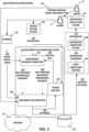
- FIG. 2 is a schematic block diagram illustrating an example patient evaluation system 120 for implementing the method 100 of analyzing a dental treatment plan described in FIG. 1 .
- the patient evaluation system 120 includes a scanner 122, a motion capture station 126, and a treatment plan generation system 130.
- a scan 124 of dentition of the patient P is captured by the scanner 122 to perform operation 102 and a dentition motion assessment 128 is performed on patient P by the motion capture station 126 to perform operation 104.
- the scan 124 and dentition motion assessment 128 are provided as input to the treatment plan generation system 130.
- the scan 124 provides a position and an orientation of each tooth in the upper and lower dental arches of the dentition with respect to each other tooth.
- the dentition motion assessment 128 comprises motion data providing the movement of the dental arches relative to each other, including how each tooth in the upper and lower dental arches move with respect to one another.
- the dentition motion assessment 128 also provides a pre-treatment interference boundary.
- the treatment plan generation system 130 determines the pre-treatment interference boundary from data associated with the scan 124 and the dentition motion assessment 128.
- the pre-treatment interference boundary is a boundary of function between teeth of opposing dental arches before a treatment plan has been implemented, and is defined by the interface or interaction between the teeth on the opposing dental arches.
- the pre-treatment interference boundary indicates how far each particular tooth can move vertically, anteroposteriorly, and transversely. If a tooth extends or crosses over the pre-treatment interference boundary in one or more planes, an interference with teeth of the opposing dental arch of the dentition is created.
- the treatment plan generation system 130 determines a dental treatment plan 132 that includes a dentition adjustment 134 to perform operation 106.
- the dentition adjustment 134 can involve any kind of change in the structure or positions of the teeth, such as a removal, re-shaping, and/or re-alignment of a portion or entirety of a tooth or teeth on one or both dental arches of the patient P's dentition, among other examples.
- the dentition adjustment 134 is defined to avoid an interference between a tooth or teeth associated with the dentition adjustment 134 and teeth of the opposing dental arch of the dentition.
- data from the scan 124 and the dentition motion assessment 128 are utilized to visualize a position and orientation of a tooth or teeth associated with the dentition adjustment 134 and how the tooth or teeth can move vertically, anteroposteriorly, and transversely to ensure that the dentition adjustment does not move or adjust the tooth or teeth beyond the confines of the pre-treatment interference boundary (e.g., does not violate the pre-treatment interference boundary to avoid introducing an interference).
- the treatment plan generation system 130 further determines a predicted motion adjustment 136 based the dentition adjustment 134 to perform operation 108. For example, a determination is made as to whether an interference will be removed after the dentition adjustment 134 and if so, a determination of associated effects of the removal of the interference (e.g., a determination of changes to the jaw motion) is made to determine the predicted motion adjustment 136.
- a post-dentition adjustment interference boundary is predicted to represent the interference boundary following the changes resulting from the removal of the interference.
- the treatment plan generation system 130 uses the predicted motion adjustment 136 to modify the dental treatment plan 132 to create a modified dental treatment plan 138 to perform operation 110. For example, if it is determined that the dentition adjustment 134 of the dental treatment plan 132 will cause changes to the jaw motion, the dental treatment plan 132 is modified to accommodate the predicted motion adjustment so that the dental treatment plan 132 continues to avoid introducing any interference. As one example, a jaw motion change may result in a change to the pre-treatment interference boundary. For example, the jaw may now be more or less extensible, and the boundary may change accordingly. Therefore, the dental treatment plan 132 is modified to the modified dental treatment plan 138 to accommodate the predicted motion adjustment 136. For example, the modified dental treatment plan 138 ensures that the dentition adjustment 134 made does not go beyond the confines of or violate the predicted post-dentition adjustment interference boundary.
- the treatment plan generation system 130 provides the modified dental treatment plan 138 as output to the dentist D such that the dentist D performs 140 the modified dental treatment plan 138 that proactively avoids introducing interferences potentially caused by both the dentition adjustment 134 and the predicted motion adjustment 136.
- FIG. 3 is another schematic block diagram illustrating another example of the patient evaluation system 120, shown in FIG. 2 , for implementing the method 100 of analyzing a dental treatment plan described in FIG. 1 .
- the example patient evaluation system 120 includes the scanner 122, the motion capture station 126, and the treatment plan generation system 130 as described in FIG. 2 .
- the treatment plan generation system 130 includes an interference boundary generator 148, a treatment plan generator 150, and a motion analyzer 152.
- the patient evaluation system 120 further comprises a rapid fabrication machine 164 and/or restoration fabrication station 168, and a restoration installation station 172.
- various components of the patient evaluation system 120 may be at least partially located within a physical dental office and/or a dental lab. Additionally, any of the computerized functions could be performed in the dental office, dental lab, or remotely by, or in cooperation with, one or more other computing devices (including client, server, or cloud computing devices), and any number of computing devices can be used to perform all or any part of the system.
- the patient evaluation system 120 may comprise a web-based service performing various functions of the system.
- the system and methods begin by scanning the dentition of the patient P to perform operation 102.
- scanner 122 performs the scan 124, from which a position and an orientation of each tooth in the upper and lower dental arches of the dentition is determined with respect to each other tooth.
- the scanner 122 can be an intraoral scanner, where example intraoral scanners include the Medit Intraoral Scanner, TRIOS Intra Oral Digital Scanner, the Lava Chairside Oral Scanner C.O.S., the Cadent iTero, the Cerec AC, the Cyrtina IntraOral Scanner, and the Lythos Digital Impression System from Ormco.
- the dentition of the patient P is captured using other imaging technologies, such as computed tomography (CT) or magnetic resonance imaging (MRI).
- CT computed tomography
- MRI magnetic resonance imaging
- the type of CT used is Dental Cone Beam CT (Dental CBCT).
- the scanner 122 is capable of creating a digital dental model 142, which is a three-dimensional digital representation of the dentition of the patient P from the scan 124.
- the scanner 122 comprises a laser scanner, a touch probe, or an industrial CT scanner, among other types of scanners capable of creating three-dimensional digital representations.
- the scanner 122 generates a point cloud, a polygonal mesh, a parametric model, or voxel data representing the dentition of the patient P.
- Some embodiments further include a segmentation tool that analyzes the digital dental model 142 generated from the scanner 122 and segments the model to separate each tooth from adjacent teeth, which is then saved into the digital dental model 142.
- the segmentation tool can be a part of the scanner 122, or can be a separate component.
- the segmentation tool can be one of a variety of tools provided by the treatment plan generator 150 described in detail in FIG. 4 .
- An example of the segmentation tool is an auto-segmentation software application. Auto-segmentation software and related techniques are described in Kumar Y, Janardan R, Larson B, Moon J. Improved segmentation of teeth in dental models.
- the dentition motion assessment 128 is performed on patient P using the motion capture station 126 to generate motion data 146 representing the movement of the dental arches relative to one another.
- the motion capture station 126 generates the motion data 146 from optical measurements of the dental arches that are captured while the dentition of the patient P is moved.
- the optical measurements are extracted from image or video data recorded while the dentition of the patient P is moved. Additionally, in some embodiments, the optical measurements are captured indirectly. For example, the optical measurements are extracted from images or video data of one or more devices that are secured to a portion of the dentition of the patient.
- still images are captured of the patient's dentition while the dentition of the patient is positioned in a plurality of bite locations.
- image processing techniques are used to determine the positions of the patient's upper and lower arches relative to each other (either directly or based on the positions of attached devices).
- the motion data 146 is generated by interpolating between the positions of the upper and lower arches determined from at least some of the captured images.
- the motion capture station 126 may comprise a patient assembly that includes a clutch to be worn by the patient P on a dentition of the patient P.
- the clutch includes a dentition coupling device to couple to the dentition of the patient P and a position indicating system rigidly connected to the dentition coupling device, where the position indicating system emits a plurality of light beams.
- the motion capture station 126 can also include an imaging system and a motion determining device, where the imaging system captures a plurality of image sets that each include at least one of a plurality of screens upon which the light beams project, and the motion determining device processes the captured image sets to determine the motion of the patient's dentition.
- the motion data 146 is generated using other processes. Further, in some embodiments, the motion data 146 includes transformation matrices that represent the position and orientation of the dental arches. Other embodiments of the motion data 146 are possible as well.
- the treatment plan generation system 130 receives the digital dental model 142 and the motion data 146 as input.
- the treatment plan generation system 130 includes one or more components and/or sub-systems including at least the interference boundary generator 148, the treatment plan generator 150, and the motion analyzer 152.
- the interference boundary generator 148 of the treatment plan generation system 130 determines a pre-treatment interference boundary 154 based on the position and orientation of each tooth provided by the digital dental model 142 and the movement of each tooth relative to one another provided by the motion data 146.
- the pre-treatment interference boundary 154 is a boundary of function between teeth of the dental arch on the upper jaw and teeth of the opposing dental arch on the lower jaw, and is defined by the interface or interaction between the teeth on the opposing dental arches before a treatment plan is implemented.
- the pre-treatment interference boundary 154 identifies for all possible positions of the dental arches, the boundary at which no teeth from the opposing arch will cross. If any teeth do cross over the pre-treatment interference boundary in one or more planes, an interference with teeth of the opposing dental arch of the dentition is created.
- the treatment plan generator 150 of the treatment plan generation system 130 determines the dental treatment plan 132.
- the dental treatment plan 132 includes at least one dentition adjustment 134 for the patient P.
- the dentition adjustment 134 involves any kind of change in the structure or positions of the teeth.
- the dentition adjustment 134 can be an occlusal equilibration, whereby a surface of a tooth on one or both dental arches is altered (e.g., by raising a surface of the tooth or grinding down the surface of the tooth) to allow the jaw joints to be in the proper anatomical location when the teeth on opposing arches come into contact.
- the dentition adjustment 134 can be a restoration preparation or a corresponding temporary or provisional restoration, such as the preparation for a crown or a bridge that involves cutting down and/or re-shaping a portion or entirety of a tooth or teeth, as described in further detail in FIG. 6 .
- the dentition adjustment 134 can be a dental alignment, such as an orthodontic alignment, as described in further detail in FIG. 7 .
- the dentition adjustment 134 involve a dental surgery that reshapes the jaw causing the change in the structure or positions of the teeth.
- the treatment plan generator 150 operates in cooperation with an operator user, such as the dentist D, to receive inputs to generate the dental treatment plan 132.
- the treatment plan generator 150 comprises at least one computing device including one or more user input devices through which input from the operator user is received.
- the treatment plan generator 150 in conjunction with the operator user, can define at least one dentition adjustment 134 of the dental treatment plan 132.
- the dentition adjustment 134 is defined to avoid an adjustment that will cause interference with teeth of the opposing dentition.
- the digital dental model 142, the motion data 146, and the pre-treatment interference boundary 154 are utilized to visualize a position and orientation of a tooth associated with the dentition adjustment 134 and how the tooth can move vertically, anteroposteriorly, and transversely to ensure that the dentition adjustment 134 does not move or adjust the tooth beyond the confines of the pre-treatment interference boundary 154 (e.g., does not violate the pre-treatment interference boundary 154 to avoid introducing an interference).
- the dental treatment plan 132 is generated as three-dimensional digital data that represents a dental treatment plan (DTP) model 156.
- DTP dental treatment plan
- the DTP model 156 comprises a three-dimensional representation of the dentition of the patient with the dentition adjustment 134.
- the treatment plan generator 150 includes computer-aided-design (CAD) software that generates a graphical display of the digital dental model 142 and, either automatically or in cooperation with the operator user generates the DTP model 156 that identifies the at least one dentition adjustment 134 from the original digital dental model 142.
- CAD computer-aided-design
- the operator user interacts with and manipulates the DTP model 156 to define the adjustments to be made, as discussed above.
- the treatment plan generator 150 comprises digital tools that mimic the tools used by laboratory technicians, as described in greater detail in FIG. 4 below. Additionally, in some embodiments, the treatment plan generator 150 comprises a computing device that partially or fully automates the generation of the DTP model 156.
- the DTP model 156 is generated to include the dentition adjustment 134 as a simulation of the dentition adjustment (e.g., without the dentition adjustment actually being performed).
- the dentition adjustment 134 can be performed according to the dental treatment plan 132, another scan of the dentition post-dentition adjustment is captured by the scanner 122, and the DTP model 156 is generated based on the post-dentition adjustment scan (e.g., the DTP model 156 is a three-dimensional representation of the patient's dentition after the dentition adjustment has been performed).
- the motion analyzer 152 of treatment plan generation system 130 predicts a motion adjustment based on the dentition adjustment 134. For example, the motion analyzer 152 analyzes the DTP model 156, along with the motion data 146, to predict what changes will occur in the patient's jaw motion as a result of the dentition adjustment 134, and then analyzes the DTP model 156 based on the predicted changes in the patient's jaw motion (e.g., to collect analysis data 158).
- a location of a screw axis of the patient's jaw is determined.
- the screw axis corresponds to the condyloid process of the temporomandibular joint of the patient P, and is an axis about which the lower jaw rotates and translates along an eminence of a condyle of the condyloid process when in function. Accordingly, the location of the screw axis imposes limitations on a range of motion of the jaw. Mathematical coordinates of the range of motion relative to the patient's dentition can be determined and used as parameters for simulating the motion of the jaw.
- j aw-related characteristics or parameters such as a flexibility or "sponginess" of the temporomandibular joint, can be determined and used as data input for simulating the motion of the jaw.
- the DTP model 156 that includes the dentition adjustment 134 can be used in conjunction with the screw axis location and other jaw-related parameters to simulate the motion of the jaw after the dentition adjustment 134, as described in greater detail in FIG. 4 , to predict the motion adjustment.
- a post-dentition adjustment interference boundary 160 is predicted based on the analysis data 158 to determine a change from the location of the pre-treatment interference boundary 154.
- the motion analyzer 152 can provide the analysis data 158 to the interference boundary generator 148, the analysis data 158 including the predicted motion adjustment 136 resulting from the dentition adjustment 134.
- the interference boundary generator 148 can generate a post-dentition adjustment interference boundary 160 based on the analysis data 158 and the DTP model 156, and provide the post-dentition adjustment interference boundary 160 to the treatment plan generator 150.
- the treatment plan generator 150 can then modify the dental treatment plan 132 as needed to create a modified dental treatment plan 138. For example, if it is determined that the dentition adjustment 134 of the dental treatment plan 132 will cause changes to the jaw motion, the dental treatment plan 132 is modified to accommodate the predicted motion adjustment so that the dental treatment plan 132 continues to avoid introducing any interference. As one example, if based on the change between the pre-treatment interference boundary 154 and the post-dentition adjustment interference boundary 160, it is determined that the dentition adjustment 134 proposed by the dental treatment plan 132 will cause an interference to be removed that subsequently will adjust a motion of the jaw, the treatment plan generator 150 modifies the dental treatment plan 132 to accommodate the predicted motion change in the modified dental treatment plan 138.
- the dentition adjustment 134 can be modified to ensure that a tooth associated with the dentition adjustment 134 does not go beyond the confines of or violate the predicted post-dentition adjustment interference boundary 160.
- the treatment plan generator 150 can then correspondingly adjust the DTP model 156 to generate a modified DTP model 162 based on the modified dental treatment plan 138.
- the treatment plan generation system 130 may store the patient's data including one or more of the scan 124, the digital dental model 142, the dentition motion assessment 128, the motion data 146, the pre-treatment interference boundary 154, the dental treatment plan 132 with dentition adjustment 134, the DTP model 156, the analysis data 158, the post-dentition adjustment interference boundary 160, the modified dental treatment plan 138, and the modified DTP model 162, among other patient data.
- the patient's data can be used to facilitate and inform future dental procedures.
- the patient's data may be stored in a database 176 associated with the treatment plan generation system 130 and/or patient evaluation system 120.
- the modified DTP model 162 includes a digital model of a restoration associated with the modified dental treatment plan 138 that can be optionally provided to a rapid fabrication machine 164.
- the rapid fabrication machine 164 comprises one or more three-dimensional printers, such as the ProJet line of printers from 3D Systems, Inc. of Rock Hill, South Carolina. Another example of the rapid fabrication machine 164 is stereolithography equipment. Yet another example of the rapid fabrication machine 164 is a milling device, such as a computer numerically controlled (CNC) milling device.
- the rapid fabrication machine 164 is configured to receive files in the STL format. Other embodiments of the rapid fabrication machine 164 are possible as well.
- the rapid fabrication machine 164 is configured to use the modified DTP model 162 to fabricate the dental restoration component 166.
- the dental restoration component 166 is a physical component that is configured to be used as part or all of the dental restoration 170.
- the dental restoration component 166 is milled from zirconium or another material that is used directly as a dental restoration 170.
- the dental restoration component 166 is a mold formed from wax or another material and is configured to be used indirectly (e.g., through a lost wax casting or ceramic pressing process) to fabricate the dental restoration 170.
- the dental restoration 170 is formed using traditional techniques (e.g., stacked porcelain or wax-up).
- underlayments and/or frameworks for the dental restoration component 166 can be printed.
- metal or ceramic underlayments and/or frameworks are printed.
- the restoration fabrication station 168 operates to fabricate the dental restoration 170 for the patient P.
- the restoration fabrication station 168 uses the modified DTP model 162 or the dental restoration component 166 produced by the rapid fabrication machine 164.
- the dental restoration 170 is a filling, partial crown, full crown, veneer, bridge, complete denture, partial denture, or implant framework. Other embodiments of the dental restoration 170 are possible as well.
- the dental restoration 170 is formed from an acrylic, ceramic, or metallic material.
- a model of the dentition of the patient P is generated by the rapid fabrication machine 164 using the scan 124 (and/or the digital dental model 142) captured by the scanner 122.
- the restoration fabrication station 168 comprises equipment and process to perform some or all of the techniques used in traditional dental laboratories to generate dental restorations. Other embodiments of the restoration fabrication station 168 are possible as well.
- the dental restoration 170 is a crown
- the crown is automatically fabricated based on the modified DTP model 162 to account for both dentition adjustment and jaw motion adjustment.
- an occlusal surface of the crown is fabricated to correspond with the predicted post-dentition adjustment interference boundary 160.
- a default crown structure is used as a starting template that is then adjusted and contoured based on the predicted post-dentition adjustment interference boundary 160.
- the predicted post-dentition adjustment interference boundary 160 is used to define contoured portions of the crown surface that interface with opposing and adjacent teeth to prevent post-dentition adjustment interference.
- one or more rules or parameters are generated to ensure that the post-dentition adjustment interference boundary 160 is not violated in any plane by the crown.
- the rules or parameters are associated with a slope of the sidewalls of the crown, in addition to a height and occlusal surface shape of the crown.
- the dentist D may seat the dental restoration 170 in the mouth of the patient P or perform another associated dental procedure in accordance with the modified dental treatment plan 138 at the restoration installation station 172. In some embodiments, the dentist D confirms that the dental restoration 170 properly corresponds to the dental preparation (e.g., the dentition adjustment 134) and the dental restoration 170 or other associated dental procedure accounts for any motion changes to the jaw caused by the dental preparation.
- the dental restoration 170 properly corresponds to the dental preparation (e.g., the dentition adjustment 134) and the dental restoration 170 or other associated dental procedure accounts for any motion changes to the jaw caused by the dental preparation.
- the network 174 is an electronic communication network that facilitates communication between the various systems and components of the patient evaluation system 120 spread across a dental office, a dental lab, and/or web-based platforms.
- An electronic communication network is a set of computing devices and links between the computing devices.
- the computing devices in the network 174 use the links to enable communication among the computing devices in the network 174.
- the network 174 can include routers, switches, mobile access points, bridges, hubs, intrusion detection devices, storage devices, standalone server devices, blade server devices, sensors, desktop computers, firewall devices, laptop computers, handheld computers, mobile telephones, and other types of computing devices.
- the network 174 includes various types of links.
- the network 174 can include one or both of wired and wireless links, including Bluetooth, ultra-wideband (UWB), 802.11, ZigBee, and other types of wireless links.
- the network 174 is implemented at various scales.
- the network 174 can be implemented as one or more local area networks (LANs), metropolitan area networks, subnets, wide area networks (such as the Internet), or can be implemented at another scale.
- LANs local area networks
- LANs local area networks
- subnets such as the Internet
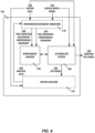
- FIG. 4 is a block diagram illustrating an example of the treatment plan generator 150 of the treatment plan generation system 130 described in FIG. 3 .
- the treatment plan generator 150 includes one or more components, including at least a three-dimensional (3D) modeling system 180 and an interference checker 182.
- treatment plan generator 150 may also include the interference boundary generator 148 and the motion analyzer 152.
- the interference boundary generator 148 and the motion analyzer 152 are separate components or sub-systems of the treatment plan generation system 130.
- the treatment plan generator 150 determines the dental treatment plan 132.
- the dental treatment plan 132 includes at least one dentition adjustment 134 for the patient P.
- the treatment plan generator 150 operates in cooperation with an operator user, such as the dentist D, to generate the dental treatment plan 132.
- the dental treatment plan 132 is three-dimensional digital data that represents a dental treatment plan (DTP) model 156.
- DTP dental treatment plan
- the 3D modeling system 180 of the treatment plan generator 150 includes computer-aided-design (CAD) software that generates a graphical display of a digital dental model 142 representing dentition of the patient P before the treatment and, either automatically or in cooperation with an operator user, such as the dentist D, generates the DTP model 156 that identifies at least one dentition adjustment 134 to be made from the original digital dental model 142.
- Example software that can be implemented by the 3D modeling system 180 include 3 Shape CAD/CAM software, Align technology iTero software, Orchestrate Orthodontic Technologies Orchestrate 3D Treatment Planning software, Forestadent Onyx software, and D4D Technologies E4D Dental System, uLab Systems dental aligner planning software, among other similar software.
- the operator interacts with and manipulates the DTP model 156 to define the dentition adjustment 134 to be made. Additionally, in other embodiments, the 3D modeling system 180 partially or fully automates the generation of the DTP model 156.
- the 3D modeling system 180 can include surgical software that is able to determine a new interference boundary (e.g., the post dentition adjustment interference boundary 160) based on changes to a horizontal and/or vertical position of one or both jaws (e.g., a realignment of the jaws) as a result of various types of surgeries.
- a new interference boundary e.g., the post dentition adjustment interference boundary 160
- changes to a horizontal and/or vertical position of one or both jaws e.g., a realignment of the jaws
- a new interference boundary based on the change in vertical dimension can be determined by the software and used to create provisional and/or permanent restorations to be attached to the surgical implant.
- the interference boundary can change as the dimensions of the jaw change. Therefore, multiple new interferences boundaries based on the various stages of change in dimension can be determined by the software (e.g., a boundary post-dental alignment and pre-surgery, a boundary post-surgery, and a boundary post-dental alignment).
- the 3D modeling system 180 comprises digital tools that mimic the tools used by laboratory technicians.
- Example tools include definition tools, movement tools, alignment tools, segmentation tools, measurement tools, and preparation tools, among other similar tools.
- these tools enable a user, such as the dentist D, to interact with and manipulate the digital dental model 142 in accordance with the motion data 146 to develop the dental treatment plan 132 and define the dentition adjustment 134 within the DTP model 156.
- the tools may be automated (e.g., do not require user interaction/manipulation).
- Definition tools can define the dentition adjustment 134 associated with the dental treatment plan 132.
- Movement tools can move the patient's dentition according to the motion data 146 (which may be similar to a physical articulator, for example).
- Alignment tools can be used to simulate an alignment of a tooth or teeth with adjacent and/or opposing teeth based on digital dental model 142. Segmentation tools segment the digital dental model 142 to separate each tooth from adjacent teeth, which is useful, for example, to allow individual teeth (or groups of teeth) within the digital dental model 142 to be moved relative to the other teeth.
- Measurement tools allow a user, such as dentist D, to perform measurements that may be needed to determine a shape, size, or type of materials that will be needed for a restoration and/or for determining the parameters for the restoration preparation (e.g., how much of and which portion of a tooth to grind, as well as how to shape).
- Preparation tools enable simulation of at least part of the dental procedure (e.g., a preparation for a restoration) on a tooth or teeth. For example, if the dental procedure is a crown restoration, a tooth may be cut down and shaped within the digital dental model 142 to simulate the crown preparation to be performed.
- the interference checker 182 is used by the 3D modeling system 180 to aid in the definition of the dentition adjustment 134 within the DTP model 156 to avoid an adjustment that will cause interference with teeth of the opposing dentition due to a tooth that projects past a pre-treatment interference boundary 154, for example.
- the pre-treatment interference boundary 154 is a boundary of function between teeth of the dental arch on the upper jaw and teeth of the opposing dental arch on the lower jaw, and is defined by the interface or interaction between the teeth on the opposing dental arches before a treatment plan is implemented.
- the interference boundary generator 148 uses the digital dental model 142 and the motion data 146 to determine and provide the pre-treatment interference boundary 154 to the interference checker 182.
- the interference checker 182 is then used in conjunction with the 3D modeling system 180 to ensure that the dentition adjustment 134 does not move or adjust the tooth or teeth beyond the confines of the pre-treatment interference boundary 154 (e.g., does not violate the pre-treatment interference boundary 154).
- the interference checker 182 identifies a violation of the pre-treatment interference boundary 154 as the 3D modeling system 180 and/or operator user are defining or manipulating the dentition adjustment 134 to generate the DTP model 156 from the original digital dental model 142, an alert may be provided within the graphical display of the digital dental model 142.
- the interference checker 182 is also configured to provide color coded indications of violations directly on the graphical display of the digital dental model 142 itself to visually show the operator user where the violations are occurring to help inform the operator how to further modify or manipulate the dentition adjustment 134 to avoid the interference.
- the motion analyzer 152 analyzes the DTP model 156, along with the motion data 146, to predict what changes will occur in the patient's jaw motion as a result of the dentition adjustment 134, and then analyzes the DTP model 156 based on the predicted changes in the patient's jaw motion to generate analysis data 158.
- a location of a screw axis of the patient's jaw is determined.
- the screw axis corresponds to the condyloid process of the temporomandibular joint of the patient, and is an axis about which the lower jaw rotates and translates along. Accordingly, the location of the screw axis imposes limitations on a range of motion of the jaw. Mathematical coordinates of the range of motion relative to the patient's dentition can be determined and used as parameters for simulating the motion of the jaw after the dentition adjustment 134 is made.
- jaw-related characteristics or parameters such as a flexibility or "sponginess" of the temporomandibular joint, can be determined and used as data input for simulating the motion of the jaw.
- the DTP model 156 that includes the dentition adjustment 134 can be used in conjunction with the screw axis location and other j aw-related parameters to simulate the motion of the jaw after the dentition adjustment 134.
- the motion adjustment prediction is determined via a simulation guided by manual inputs and manipulations of a user, such as the dentist D, to a digital articulator.
- the digital articulator can be displayed through a user interface of a computing device and the dentist D can interact with the digital articular using input devices of the computing device, such as a touch input device, a mouse, a keyboard, or a joystick, among other input devices.
- the digital articulator includes the DTP model 156 defining the dentition adjustment 134, and the user can use the input devices to manually shift the lower jaw of the DTP model 156 within the simulation.
- the lower jaw is manually shifted up and down, forward and back, and side to side to collect analysis data 158 within the range of motion permitted by the screw axis location and other jaw-related characteristics or parameters for determining whether an interference present in the pre-treatment dentition that restricted the motion of the jaw has been removed as a result of the dentition adjustment 134 defined in the DTP model 156.
- a post-dentition adjustment interference boundary 160 is determined by the interference boundary generator 148 based on analysis data 158 collected during the manual shifting, and can be compared to the pre-treatment interference boundary 154 to determine whether an interference has been removed.
- the motion adjustment prediction is determined via a simulation employing artificial intelligence to perform automated shifting of the lower jaw of the DTP model 156 within the digital articulator.
- the lower jaw within the above-described simulation is automatically shifted up and down, forward and back, and side to side within the range of motion permitted by the screw axis location and other jaw-related characteristics or parameters to collect analysis data 158 for determining whether an interference present in the pre-treatment dentition that restricted the motion of the jaw has been removed as a result of the dentition adjustment 134 defined in the DTP model 156.
- the post-dentition adjustment interference boundary 160 is determined by the interference boundary generator 148 based on analysis data 158 collected during the automatic shifting, and can be compared to the pre-treatment interference boundary 154 to determine whether an interference has been removed.
- data points are recorded at a plurality of different three dimensional points within an xyz space to determine one or more directions and a magnitude thereof that each tooth of the dentition moves as the lower jaw of the DTP model 156 is moved within the xyz space to predict the post-dentition adjustment interference boundary 160.
- a reference point may be selected within the jaw.
- the analysis data 158 comprises the recorded data points, which are utilized by the interference boundary generator 148 to determine the post-dentition adjustment interference boundary 160, which can be compared to the pre-treatment interference boundary 154 to determine whether an interference has been removed.
- the 3D modeling system 180 can then modify the dental treatment plan 132 as needed to accommodate for the predicted motion adjustment (e.g., to ensure that the dentition adjustment 134 made does not go beyond the confines of or violate the predicted post-dentition adjustment interference boundary 160).
- the 3D modeling system 180 can correspondingly adjust the DTP model 156 to generate a modified DTP model 162.
- the modified DTP model 162 is then provided as output of the treatment plan generator 150.
- FIG. 5 illustrates an exemplary architecture of a computing device 190 that can be used to implement aspects of the present disclosure, including any of the plurality of computing devices described herein, such as a computing device of the patient evaluation system 120, the scanner 122, the motion capture station 126, the treatment plan generation system 130, the interference boundary generator 148, the treatment plan generator 150, the 3D modeling system 180, the interference checker 182, the motion analyzer 152, the rapid fabrication machine 164, the restoration fabrication station 168, or any other computing devices that may be utilized in the various possible embodiments.
- a computing device of the patient evaluation system 120 the scanner 122, the motion capture station 126, the treatment plan generation system 130, the interference boundary generator 148, the treatment plan generator 150, the 3D modeling system 180, the interference checker 182, the motion analyzer 152, the rapid fabrication machine 164, the restoration fabrication station 168, or any other computing devices that may be utilized in the various possible embodiments.
- the computing device illustrated in FIG. 5 can be used to execute the operating system, application programs, and software modules (including the software engines) described herein.
- the computing device 190 includes, in some embodiments, at least one processing device 192, such as a central processing unit (CPU).
- processing device 192 such as a central processing unit (CPU).
- CPU central processing unit
- a variety of processing devices are available from a variety of manufacturers, for example, Intel or Advanced Micro Devices.
- the computing device 190 also includes a system memory 194, and a system bus 196 that couples various system components including the system memory 194 to the processing device 192.
- the system bus 196 is one of any number of types of bus structures including a memory bus, or memory controller; a peripheral bus; and a local bus using any of a variety of bus architectures.
- Examples of computing devices suitable for the computing device 190 include a desktop computer, a laptop computer, a tablet computer, a mobile computing device (such as a smart phone, an iPod ® or iPad ® mobile digital device, or other mobile devices), or other devices configured to process digital instructions.
- a desktop computer such as a laptop computer, a tablet computer
- a mobile computing device such as a smart phone, an iPod ® or iPad ® mobile digital device, or other mobile devices
- the system memory 194 includes read only memory 198 and random access memory 200.
- the computing device 190 also includes a secondary storage device 204 in some embodiments, such as a hard disk drive, for storing digital data.
- the secondary storage device 204 is connected to the system bus 196 by a secondary storage interface 206.
- the secondary storage device 204 and their associated computer readable media provide nonvolatile storage of computer readable instructions (including application programs and program modules), data structures, and other data for the computing device 190.
- exemplary environment described herein employs a hard disk drive as a secondary storage device
- other types of computer readable storage media are used in other embodiments. Examples of these other types of computer readable storage media include flash memory cards, digital video disks, compact disc read only memories, digital versatile disk read only memories, random access memories, or read only memories. Some embodiments include nontransitory media. Additionally, such computer readable storage media can include local storage or cloud-based storage.
- a number of program modules can be stored in secondary storage device 204 or system memory 194, including an operating system 208, one or more application programs 210, other program modules 212 (such as the software engines described herein), and program data 214.
- the computing device 190 can utilize any suitable operating system, such as Microsoft Windows TM , Google Chrome TM OS, Apple OS, Unix, or Linux and variants and any other operating system suitable for a computing device. Other examples can include Microsoft, Google, or Apple operating systems, or any other suitable operating system used in tablet computing devices.
- a user provides inputs to the computing device 190 through one or more input devices 216.
- input devices 216 include a keyboard 218, mouse 220, microphone 222, and touch sensor 224 (such as a touchpad or touch sensitive display).
- touch sensor 224 such as a touchpad or touch sensitive display
- Other embodiments include other input devices 216.
- the input devices are often connected to the processing device 192 through an input/output interface 226 that is coupled to the system bus 196. These input devices 216 can be connected by any number of input/output interfaces, such as a parallel port, serial port, game port, or a universal serial bus.
- Wireless communication between input devices and the input/output interface 226 is possible as well, and includes infrared, BLUETOOTH ® wireless technology, IEEE 802.11a/b/g/n, cellular, ultra-wideband (UWB), ZigBee, LoRa, or other radio frequency communication systems in some possible embodiments.
- the computing device 190 can include various other peripheral devices (not shown), such as speakers or a printer.
- the computing device 190 When used in a local area networking environment or a wide area networking environment (such as the Internet), the computing device 190 is typically connected to the network through a network interface 232, such as an Ethernet interface. Other possible embodiments use other communication devices. For example, some embodiments of the computing device 190 include a modem for communicating across the network.
- the computing device 190 typically includes at least some form of computer readable media.
- Computer readable media includes any available media that can be accessed by the computing device 190.
- Computer readable media include computer readable storage media and computer readable communication media.
- Computer readable storage media includes volatile and nonvolatile, removable and non-removable media implemented in any device configured to store information such as computer readable instructions, data structures, program modules or other data.
- Computer readable storage media includes, but is not limited to, random access memory, read only memory, electrically erasable programmable read only memory, flash memory or other memory technology, compact disc read only memory, digital versatile disks or other optical storage, magnetic cassettes, magnetic tape, magnetic disk storage or other magnetic storage devices, or any other medium that can be used to store the desired information and that can be accessed by the computing device 190.
- Computer readable communication media typically embodies computer readable instructions, data structures, program modules or other data in a modulated data signal such as a carrier wave or other transport mechanism and includes any information delivery media.
- modulated data signal refers to a signal that has one or more of its characteristics set or changed in such a manner as to encode information in the signal.
- computer readable communication media includes wired media such as a wired network or direct-wired connection, and wireless media such as acoustic, radio frequency, infrared, and other wireless media. Combinations of any of the above are also included within the scope of computer readable media.
- the computing device illustrated in FIG. 5 is also an example of programmable electronics, which may include one or more such computing devices, and when multiple computing devices are included, such computing devices can be coupled together with a suitable data communication network so as to collectively perform the various functions, methods, or operations disclosed herein.
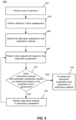
- FIG. 6 is a flow chart illustrating an example method 240 of predicting a motion adjustment responsive to a restoration preparation.
- the method 240 includes operations 242, 244, 246, 248, 250, 252, and 254.
- Example dental procedures involving dentition adjustments may include dental restorations and dental alignment. The first example is illustrated and described in more detail with reference to FIG. 6 , and the second example is illustrated and described in more detail with reference to FIG. 7 .
- dental restorations involve two steps: preparation of the tooth or teeth for placement of restorative materials (i.e., a restoration preparation) and the placement of the restorative materials.
- Example dental restorations include dental implants, bridges, and/or crowns, among other similar dental procedures.
- the example method 240 can be implemented by various components of the patient evaluation system 120 described above with reference to FIGS. 2 through 4 .
- a scan 124 of dentition is performed prior to the preparation and/or placement of the restorative materials. Based on the scan 124, a position and orientation of each tooth in the upper and lower dental arches of the dentition is determined with respect to each other tooth.
- a dentition motion assessment 128 is performed. The dentition motion assessment 128 captures a representation of the movement of the dental arches relative to each other. For example, the dentition motion assessment 128 captures how each tooth in the upper and lower dental arches move with respect to one another.
- An interference boundary prior to the restoration preparation (e.g., a pre-treatment interference boundary 154) can be determined from the scan 124 and the dentition motion assessment 128.
- the pre-treatment interference boundary 154 is a boundary of function between teeth of the dental arch on the upper jaw and teeth of the opposing dental arch on the lower jaw, and is defined by the interface or interaction between teeth on opposing dental arches.
- the pre-treatment interference boundary 154 indicates how far each particular tooth can vertically, anteroposteriorly, and transversely. If a tooth extends or crosses over the pre-treatment interference boundary in one or more planes, an interference with teeth of the opposing dental arch of the dentition is created.
- the restoration preparation can involve a removal and/or shaping of one or more portions of a tooth or teeth.
- the restoration preparation is a crown preparation that involves grinding off a top part of the tooth to replace with a crown.
- the restoration preparation is a bridge preparation that involves grinding off a top part of multiple teeth to replace with a bridge.
- the restoration preparation is a dental implant preparation that involves removal of the entire tooth to be replaced with an implant.
- the restoration preparation is determined using the scan 124, data from the dentition motion assessment 128, and the determined pre-treatment interference boundary 154. For example, a position and orientation of a tooth associated with the restoration is visualized using the scan 124 and motion data 146 to determine how the tooth associated with the restoration preparation can move vertically, anteroposteriorly, and transversely ensure that the how the tooth is prepared (e.g., what portions of the tooth are being removed or how the tooth is shaped) does not move or adjust the tooth beyond the confines of or violate the pre-treatment interference boundary 154 to avoid introducing an interference.
- the how the tooth is prepared e.g., what portions of the tooth are being removed or how the tooth is shaped
- the determination of the restorative material includes determining a type of material to use to replace or cover the one or more portions of the tooth or teeth removed and/or shaped in the restoration preparation. Based on a type of the restoration preparation, certain types of restorative material can be more advantageous to use due to the properties of the materials, such as a durability of the material or a malleability of the material. A size of the material, including a thickness of material, can also be determined.
- a motion adjustment based on the restoration preparation is predicted.
- the restoration preparation determined at operation 246 is a crown preparation that will require the cutting or grinding down of a tooth or set of teeth
- the additional space provided by the crown preparation may actually modify the patient's bite and jaw motion by removing an interference that had been previously restricting the motion of the jaw.
- This modification to the bite and jaw motion may result in the need to further modify the restoration preparation and/or restorative materials determined at operation 246 to avoid interferences resulting from the modifications.
- the jaw can now move more freely in one or more directions causing the teeth to move relative to one another in different ways (e.g., a particular tooth can now move further vertically, anteroposteriorly, or transversely). Accordingly, the motion adjustment can affect the pre-treatment interference boundary 154.
- the post-preparation interference boundary is defined by the interface or interaction between the teeth on the opposing dental arches after the restoration preparation is performed.
- the post-preparation interference boundary can be compared to the pre-treatment interference boundary 154 to measure a change that has occurred, where the change (e.g., a net reduction) between the two interference boundaries can be used to determine whether the dentition has been sufficiently prepared for the placement of the restorative material.
- a particular amount of reduction (e.g., cutting or grinding down of the tooth) is required so that a restorative material of a sufficient thickness (e.g., for stability) can be placed over the prepared tooth without causing interference.
- a restorative material of a sufficient thickness e.g., for stability
- dental restoration involves two steps: preparation of the tooth for placement of restorative materials (i.e., restoration preparation) and the placement of the restorative materials.
- Restoration preparation includes a change to a structure or shape of a tooth or teeth. For example, grinding down a tooth to a certain size and shape, so that it may be covered with restorative material (e.g. a crown) or extracting one or more teeth for installation of a dental implant or a bridge.
- the restoration preparation and restorative materials are determined based on the pre-treatment interference boundary 154 to avoid introducing interference.
- the restoration preparation and restorative materials are initially determined to meet a required clearance, which ensures a proper fit enabling the patient P to maintain a same or similar bite pre-treatment and post-dentition adjustment (e.g., a tooth and restorative material when placed over the tooth does not extend or cross over the pre-treatment interference boundary 154 in one or more planes to avoid introducing interference).
- any adjustments to the motion of the jaw resulting from the restoration preparation of the tooth e.g., due to a removal of an interference
- the required clearance could either increase or decrease in size due to a change in the pre-treatment interference boundary 154, and the restoration preparation and restorative materials may no longer avoid interference.
- a vertical height of the restorative material such as a crown, may now be too tall for the space causing a new interference with opposing teeth.
- the restoration preparation is performed and the restorative material is placed at operation 252.
- the portions of the tooth are removed and/or shaped according to the initial restoration preparation determined, and the portions removed can be replaced with the initial restorative materials determined.
- one or more of the restorative material and the restoration preparation are modified at operation 254.
- the restoration preparation and/or restorative material are modified to correspond to the predicted post-preparation interference boundary.
- a size or a thickness of the restorative material can be modified or a different type of restorative material can be used.
- the restoration preparation will remove an interference and cause a motion adjustment of the jaw that lowers a height of clearance for the restorative materials being placed (e.g., the motion adjustment brings upper and lower dentition closer together leaving less space for the restorative material), a size or thickness of the restorative material is reduced.
- properties of the restorative material cannot be reduced below a certain size or thickness and thus a new restorative material will be selected.
- the restoration preparation itself is adjusted. For example, a tooth being prepared can be ground or cut down to a different height or shape that will enable the restorative material to be placed.
- both the restorative material and the restoration preparation are modified.
- the crown when the restoration preparation includes a crown preparation and the restorative material is a crown, the crown can be automatically generated to account for the motion adjustment. For example, an occlusal surface of the crown may be generated digitally to correspond with the predicted post-preparation interference boundary.
- a default crown structure is used as a starting template that is then adjusted and contoured based on the predicted post-preparation interference boundary.
- the predicted post-preparation interference boundary is used to define contoured portions of the crown surface that interface with opposing and adjacent teeth to prevent introducing interference.
- one or more rules or parameters are generated to ensure that the boundary is not violated in any plane by the crown as it is being digitally generated.
- the rules or parameters may be associated with a slope of the sidewalls of the crown, in addition to a height and shape of the crown.
- the operations 248, 250, and 254 can be repeated one or more times until the restorative material and the restoration preparation do not cause an interference.
- the process can be iteratively repeated to modify the restorative material or restoration preparation, predict motion based on the modified restoration preparation, and further modify the restorative material or restoration reparation based on whether the restorative material and restoration preparation cause an interference based on the predicted motion.
- FIG. 7 is a flow chart illustrating an example method 260 of predicting a motion adjustment responsive to a dental alignment plan.
- the dental alignment plan involves adjustment of position and/or alignment of the teeth in three planes of space, which can be accomplished using braces, retainers, or other dental alignment tools.
- the example method 260 can be implemented by various components of the patient evaluation system 120 described above in FIGS. 2 through 4 .
- the method 260 includes operations 262, 264, 266, 268, 270, 272, and 274.
- a scan 124 of dentition is performed. Based on the scan 124, a position and orientation of each tooth in the upper and lower dental arches is determined with respect to each other tooth.
- a dentition motion assessment 128 is performed.
- the dentition motion assessment 128 captures a representation of the movement of the dental arches relative to each other. For example, the dentition motion assessment 128 captures how each tooth in the upper and lower dental arches move with respect to one another. The movement is captured as motion data 146.
- an interference boundary prior to the dental alignment (e.g., a pre-treatment interference boundary 154) can be determined.
- the pre-treatment interference boundary 154 is a boundary of function between teeth of the dental arch on the upper jaw and teeth of the opposing dental arch on the lower jaw, and is defined by the interface or interaction between teeth on opposing dental arches.
- the pre-treatment interference boundary 154 indicates how far a particular tooth can move vertically, anteroposteriorly, and transversely. If a tooth extends or crosses over the pre-treatment interference boundary 154 in one or more planes, an interference with teeth of the opposing dental arch of the dentition is created.
- a dental alignment plan is determined using the scan 124 of the dentition, motion data 146 from the dentition motion assessment 128, and the pre-treatment interference boundary 154. For example, utilizing the scan 124 and motion data 146, a position and orientation of a tooth associated with the alignment and how the tooth can move vertically, anteroposteriorly, and transversely can be visualized to ensure that how the tooth is aligned (e.g., a direction or orientation of the alignment) does not move or adjust the tooth beyond the confines of the pre-treatment interference boundary 154 to avoid introducing an interference.
- a motion adjustment based on the dental alignment plan is predicted.
- the new position and orientation of the straight tooth can cause the patient's bite and jaw motion to change.
- This change to the bite and jaw motion may result in the need to further modify the dental alignment plan determined at operation 246 to avoid interferences resulting from the changes.
- the motion of the jaw may be more restricted in one or more directions causing the teeth to move relative to one another in different ways.
- the tooth once straightened can no longer move as far vertically, anteroposteriorly, or transversely before interfacing with opposing teeth. Accordingly, the motion adjustment can affect the pre-treatment interference boundary 154.
- the post-alignment interference boundary is defined by the interface or interaction between the teeth on the opposing dental arches after the dental alignment.
- an interference is identified and analyzed based on the predicted motion adjustment. For example, in some embodiments, the interference is identified and analyzed by comparing the pre-treatment interference boundary 154 to the post-alignment interference boundary.
- the dental alignment is modified to reduce the interference.
- the dental alignment plan is modified and the modified dental alignment can be further analyzed to see if the interference has been removed. If not, the plan can be iteratively modified until the interference has been eliminated or is less than a predetermined threshold amount.
- the operations 268, 270, and 272 can be repeated one or more times to adjust the dental alignment, predict motion based on the adjusted dental alignment, identify and analyze interference based on the predicted motion, and further adjust the dental alignment based on identified interference until interference is eliminated, or until the interference is less than a predetermined amount. Once the interference is eliminated, or the interference is less than the predetermined amount, the dental alignment can be performed according to the adjusted dental alignment at operation 274.
Landscapes
- Health & Medical Sciences (AREA)
- Life Sciences & Earth Sciences (AREA)
- Public Health (AREA)
- General Health & Medical Sciences (AREA)
- Oral & Maxillofacial Surgery (AREA)
- Dentistry (AREA)
- Epidemiology (AREA)
- Engineering & Computer Science (AREA)
- Animal Behavior & Ethology (AREA)
- Veterinary Medicine (AREA)
- Medical Informatics (AREA)
- Biomedical Technology (AREA)
- Pathology (AREA)
- Physics & Mathematics (AREA)
- Biophysics (AREA)
- Primary Health Care (AREA)
- Surgery (AREA)
- Physiology (AREA)
- Heart & Thoracic Surgery (AREA)
- Molecular Biology (AREA)
- Radiology & Medical Imaging (AREA)
- Nuclear Medicine, Radiotherapy & Molecular Imaging (AREA)
- General Engineering & Computer Science (AREA)
- Data Mining & Analysis (AREA)
- Databases & Information Systems (AREA)
- Computer Vision & Pattern Recognition (AREA)
- Optics & Photonics (AREA)
- Dental Tools And Instruments Or Auxiliary Dental Instruments (AREA)
Applications Claiming Priority (4)
| Application Number | Priority Date | Filing Date | Title |
|---|---|---|---|
| US201962822044P | 2019-03-21 | 2019-03-21 | |
| US201962941355P | 2019-11-27 | 2019-11-27 | |
| EP20717532.4A EP3941386B1 (de) | 2019-03-21 | 2020-03-18 | Voraussagesystem für bewegungseinstellung |
| PCT/US2020/023295 WO2020191017A1 (en) | 2019-03-21 | 2020-03-18 | Motion adjustment prediction system |
Related Parent Applications (1)
| Application Number | Title | Priority Date | Filing Date |
|---|---|---|---|
| EP20717532.4A Division EP3941386B1 (de) | 2019-03-21 | 2020-03-18 | Voraussagesystem für bewegungseinstellung |
Publications (2)
| Publication Number | Publication Date |
|---|---|
| EP4510148A2 true EP4510148A2 (de) | 2025-02-19 |
| EP4510148A3 EP4510148A3 (de) | 2025-04-30 |
Family
ID=70190251
Family Applications (2)
| Application Number | Title | Priority Date | Filing Date |
|---|---|---|---|
| EP24215660.2A Pending EP4510148A3 (de) | 2019-03-21 | 2020-03-18 | System zur vorhersage der bewegungsanpassung |
| EP20717532.4A Active EP3941386B1 (de) | 2019-03-21 | 2020-03-18 | Voraussagesystem für bewegungseinstellung |
Family Applications After (1)
| Application Number | Title | Priority Date | Filing Date |
|---|---|---|---|
| EP20717532.4A Active EP3941386B1 (de) | 2019-03-21 | 2020-03-18 | Voraussagesystem für bewegungseinstellung |
Country Status (4)
| Country | Link |
|---|---|
| US (1) | US12295725B2 (de) |
| EP (2) | EP4510148A3 (de) |
| CA (1) | CA3134554A1 (de) |
| WO (1) | WO2020191017A1 (de) |
Families Citing this family (3)
| Publication number | Priority date | Publication date | Assignee | Title |
|---|---|---|---|---|
| WO2022125577A1 (en) * | 2020-12-10 | 2022-06-16 | Hultgren Dental Technologies, Llc | Motion adjustment prediction system |
| US11116606B1 (en) | 2021-01-06 | 2021-09-14 | Arkimos Ltd. | Systems and methods for determining a jaw curve |
| US20220401182A1 (en) * | 2021-06-16 | 2022-12-22 | Align Technology, Inc. | Systems and methods for dental treatment |
Citations (1)
| Publication number | Priority date | Publication date | Assignee | Title |
|---|---|---|---|---|
| US20170312065A1 (en) | 2016-04-28 | 2017-11-02 | VisionEx LLC | Determining jaw movement |
Family Cites Families (35)
| Publication number | Priority date | Publication date | Assignee | Title |
|---|---|---|---|---|
| US4169314A (en) * | 1977-09-27 | 1979-10-02 | Hay Louis E | Dental articulator for mounting casts without plaster |
| DE3636671A1 (de) * | 1986-09-11 | 1988-03-17 | Neumeyer Stefan | Verfahren zur dreidimensionalen bestimmung der relativbewegung zwischen zwei koerpern sowie messanordnung zur durchfuehrung dieses verfahrens |
| US6152731A (en) | 1997-09-22 | 2000-11-28 | 3M Innovative Properties Company | Methods for use in dental articulation |
| US6808659B2 (en) * | 1998-07-10 | 2004-10-26 | Jeneric/Pentron Incorporated | Solid free-form fabrication methods for the production of dental restorations |
| US7160110B2 (en) | 1999-11-30 | 2007-01-09 | Orametrix, Inc. | Three-dimensional occlusal and interproximal contact detection and display using virtual tooth models |
| US6915178B2 (en) * | 2000-09-06 | 2005-07-05 | O'brien Dental Lab, Inc. | Dental prosthesis manufacturing process, dental prosthesis pattern & dental prosthesis made thereby |
| NL1016420C2 (nl) | 2000-10-17 | 2002-04-18 | Tno | Werkwijze voor het bepalen van een computermodel voor een tandtechnisch object, zoals een kroon. |
| US20050042577A1 (en) * | 2003-08-19 | 2005-02-24 | Kvitrud James R. | Dental crown forms and methods |
| US7118375B2 (en) * | 2004-01-08 | 2006-10-10 | Duane Milford Durbin | Method and system for dental model occlusal determination using a replicate bite registration impression |
| US7824346B2 (en) * | 2004-03-11 | 2010-11-02 | Geodigm Corporation | Determining condyle displacement utilizing electronic models of dental impressions having a common coordinate system |
| US20090068617A1 (en) * | 2006-03-03 | 2009-03-12 | Lauren Mark D | Method Of Designing Dental Devices Using Four-Dimensional Data |
| BRPI0720906B8 (pt) * | 2007-01-10 | 2021-06-22 | Nobel Biocare Services Ag | método e sistema para planejar um procedimento restaurativo dental e sistema de computador para realizar o método |
| US20090148816A1 (en) * | 2007-01-11 | 2009-06-11 | Geodigm Corporation | Design of dental appliances |
| EP2109414A2 (de) * | 2007-01-11 | 2009-10-21 | Geodigm Corporation | Entwurf zahnärztlicher anwendungen |
| WO2009140582A2 (en) * | 2008-05-16 | 2009-11-19 | Geodigm Corporation | Method and apparatus for combining 3d dental scans with other 3d data sets |
| MX2012009824A (es) | 2010-02-25 | 2013-05-06 | 3Shape As | Articulador virtual dinamico. |
| US8753114B2 (en) * | 2010-02-26 | 2014-06-17 | William C. Vuillemot | Method for dental restoration and related kit |
| US8366445B2 (en) * | 2010-02-26 | 2013-02-05 | Vuillemot William C | Method for dental restoration and related kit |
| EP2389892A1 (de) * | 2010-05-27 | 2011-11-30 | 3M Innovative Properties Company | Verfahren zur Herstellung eines Zahnersatzes |
| US8769822B2 (en) * | 2010-11-19 | 2014-07-08 | Geodigm Corporation | Method for manufacturing a dental prosthesis |
| DE102011055356A1 (de) | 2011-11-15 | 2013-05-16 | Ludwig-Maximilians-Universität München | Abformvorrichtung und Verfahren zur dreidimensionalen Erfassung von intraoralen Strukturen sowie eine entsprechende Einscanvorrichtung |
| AU2013221673B2 (en) * | 2012-02-14 | 2017-10-19 | Jr. Ronald G. Presswood | Method and apparatus for dental articulation |
| AU2014284375B2 (en) * | 2013-07-01 | 2018-10-04 | R Joseph Magness | Dental appliance for treatment of bruxism |
| CA2864357C (en) * | 2013-09-18 | 2021-03-16 | Panthera Dental Inc. | Set of occlusal splints and method of making same |
| US10537406B2 (en) * | 2014-02-21 | 2020-01-21 | Align Technology, Inc. | Dental appliance with repositioning jaw elements |
| US10299894B2 (en) * | 2014-02-21 | 2019-05-28 | Align Technology, Inc. | Treatment plan specific bite adjustment structures |
| US9848964B2 (en) | 2014-04-24 | 2017-12-26 | Bruce Willard Hultgren | System and method for fabricating a dental restoration |
| US9861458B2 (en) | 2014-04-24 | 2018-01-09 | Bruce Willard Hultgren | System and method for fabricating a dental restoration |
| US11147652B2 (en) * | 2014-11-13 | 2021-10-19 | Align Technology, Inc. | Method for tracking, predicting, and proactively correcting malocclusion and related issues |
| US10588776B2 (en) * | 2015-01-13 | 2020-03-17 | Align Technology, Inc. | Systems, methods, and devices for applying distributed forces for mandibular advancement |
| US10213277B2 (en) | 2015-06-09 | 2019-02-26 | Align Technology, Inc. | Dental appliance binding structure |
| US10952821B2 (en) * | 2016-09-21 | 2021-03-23 | uLab Systems, Inc. | Combined orthodontic movement of teeth with temporomandibular joint therapy |
| WO2018057547A1 (en) * | 2016-09-21 | 2018-03-29 | Gardner William Graham | Dental appliance for use as an aligner and as a tool to reduce temporomandibular dysfunction |
| EP3585296A4 (de) | 2017-02-22 | 2021-03-17 | Cyberdontics (USA), Inc. | Automatisiertes zahnbehandlungssystem |
| EP3644891B1 (de) * | 2017-06-30 | 2022-02-16 | Align Technology, Inc. | Computerimplementiertes verfahren und system zum entwurf und/oder zur herstellung von kieferorthopädischen vorrichtungen zur behandlung oder prävention von kiefergelenkstörungen |
-
2020
- 2020-03-18 EP EP24215660.2A patent/EP4510148A3/de active Pending
- 2020-03-18 CA CA3134554A patent/CA3134554A1/en active Pending
- 2020-03-18 EP EP20717532.4A patent/EP3941386B1/de active Active
- 2020-03-18 WO PCT/US2020/023295 patent/WO2020191017A1/en not_active Ceased
- 2020-03-18 US US16/823,056 patent/US12295725B2/en active Active
Patent Citations (1)
| Publication number | Priority date | Publication date | Assignee | Title |
|---|---|---|---|---|
| US20170312065A1 (en) | 2016-04-28 | 2017-11-02 | VisionEx LLC | Determining jaw movement |
Non-Patent Citations (1)
| Title |
|---|
| KUMAR YJANARDAN RLARSON BMOON J: "Computer-Aided Design and Applications", vol. 8, 2011, CAD SOLUTIONS, LLC, article "Improved segmentation of teeth in dental models", pages: 211 - 224 |
Also Published As
| Publication number | Publication date |
|---|---|
| CA3134554A1 (en) | 2020-09-24 |
| US12295725B2 (en) | 2025-05-13 |
| WO2020191017A1 (en) | 2020-09-24 |
| EP4510148A3 (de) | 2025-04-30 |
| EP3941386B1 (de) | 2024-12-04 |
| EP3941386A1 (de) | 2022-01-26 |
| US20200297245A1 (en) | 2020-09-24 |
| EP3941386C0 (de) | 2024-12-04 |
Similar Documents
| Publication | Publication Date | Title |
|---|---|---|
| US10265150B2 (en) | System and method for fabricating a dental restoration | |
| RU2567604C2 (ru) | Динамический виртуальный артикулятор | |
| US20230139151A1 (en) | System and method for fabricating a dental restoration | |
| EP2026285B1 (de) | System zum Betrachten der Zähne | |
| JP2025115347A (ja) | 複数の歯科構造スキャンからのデータを組み合わせること | |
| EP3349680B1 (de) | Verfahren zur erzeugung eines flexiblen bogenmodells der zähne zur verwendung in der restaurativen zahnmedizin | |
| KR102146178B1 (ko) | 점진적 치아교정에 대한 잇몸 적응들의 가상 모델링 및 연관된 기구 제조 방법 | |
| US9694539B2 (en) | Endodontic treatment simulation system | |
| EP3831331A1 (de) | Systeme und verfahren zur bestimmung von kieferorthopädischen behandlungen | |
| RU2526270C2 (ru) | Стоматологические модели с использованием стереолитографии | |
| US12295725B2 (en) | Motion adjustment prediction system | |
| US20240299131A1 (en) | Motion adjustment prediction system | |
| US20250177091A1 (en) | System and method for fabricating a dental restoration | |
| KR20240085700A (ko) | 딥러닝에 기반한 치아 상태 판별 시스템 및 방법 | |
| US20250064564A1 (en) | Digital dental model with measurement features | |
| US20240398510A1 (en) | Remote orthodontic progress tracking using physical bite impressions | |
| WO2016210323A1 (en) | System and method for fabricating a dental restoration |
Legal Events
| Date | Code | Title | Description |
|---|---|---|---|
| PUAI | Public reference made under article 153(3) epc to a published international application that has entered the european phase |
Free format text: ORIGINAL CODE: 0009012 |
|
| STAA | Information on the status of an ep patent application or granted ep patent |
Free format text: STATUS: THE APPLICATION HAS BEEN PUBLISHED |
|
| AC | Divisional application: reference to earlier application |
Ref document number: 3941386 Country of ref document: EP Kind code of ref document: P |
|
| AK | Designated contracting states |
Kind code of ref document: A2 Designated state(s): AL AT BE BG CH CY CZ DE DK EE ES FI FR GB GR HR HU IE IS IT LI LT LU LV MC MK MT NL NO PL PT RO RS SE SI SK SM TR |
|
| REG | Reference to a national code |
Ref country code: DE Ref legal event code: R079 Free format text: PREVIOUS MAIN CLASS: G16H0050200000 Ipc: A61C0009000000 |
|
| PUAL | Search report despatched |
Free format text: ORIGINAL CODE: 0009013 |
|
| AK | Designated contracting states |
Kind code of ref document: A3 Designated state(s): AL AT BE BG CH CY CZ DE DK EE ES FI FR GB GR HR HU IE IS IT LI LT LU LV MC MK MT NL NO PL PT RO RS SE SI SK SM TR |
|
| RIC1 | Information provided on ipc code assigned before grant |
Ipc: G16H 50/20 20180101ALI20250325BHEP Ipc: A61C 19/045 20060101ALI20250325BHEP Ipc: A61C 13/00 20060101ALI20250325BHEP Ipc: A61C 7/00 20060101ALI20250325BHEP Ipc: A61C 9/00 20060101AFI20250325BHEP |
|
| STAA | Information on the status of an ep patent application or granted ep patent |
Free format text: STATUS: REQUEST FOR EXAMINATION WAS MADE |
|
| 17P | Request for examination filed |
Effective date: 20251029 |