EP4509842A1 - Conformal multi-function air-data probes - Google Patents
Conformal multi-function air-data probes Download PDFInfo
- Publication number
- EP4509842A1 EP4509842A1 EP24194673.0A EP24194673A EP4509842A1 EP 4509842 A1 EP4509842 A1 EP 4509842A1 EP 24194673 A EP24194673 A EP 24194673A EP 4509842 A1 EP4509842 A1 EP 4509842A1
- Authority
- EP
- European Patent Office
- Prior art keywords
- mandrel
- bulkhead
- fluid communication
- air
- data
- Prior art date
- Legal status (The legal status is an assumption and is not a legal conclusion. Google has not performed a legal analysis and makes no representation as to the accuracy of the status listed.)
- Pending
Links
Images
Classifications
-
- G—PHYSICS
- G01—MEASURING; TESTING
- G01P—MEASURING LINEAR OR ANGULAR SPEED, ACCELERATION, DECELERATION, OR SHOCK; INDICATING PRESENCE, ABSENCE, OR DIRECTION, OF MOVEMENT
- G01P5/00—Measuring speed of fluids, e.g. of air stream; Measuring speed of bodies relative to fluids, e.g. of ship, of aircraft
- G01P5/14—Measuring speed of fluids, e.g. of air stream; Measuring speed of bodies relative to fluids, e.g. of ship, of aircraft by measuring differences of pressure in the fluid
- G01P5/16—Measuring speed of fluids, e.g. of air stream; Measuring speed of bodies relative to fluids, e.g. of ship, of aircraft by measuring differences of pressure in the fluid using Pitot tubes, e.g. Machmeter
- G01P5/165—Arrangements or constructions of Pitot tubes
-
- B—PERFORMING OPERATIONS; TRANSPORTING
- B64—AIRCRAFT; AVIATION; COSMONAUTICS
- B64D—EQUIPMENT FOR FITTING IN OR TO AIRCRAFT; FLIGHT SUITS; PARACHUTES; ARRANGEMENT OR MOUNTING OF POWER PLANTS OR PROPULSION TRANSMISSIONS IN AIRCRAFT
- B64D43/00—Arrangements or adaptations of instruments
- B64D43/02—Arrangements or adaptations of instruments for indicating aircraft speed or stalling conditions
-
- G—PHYSICS
- G01—MEASURING; TESTING
- G01P—MEASURING LINEAR OR ANGULAR SPEED, ACCELERATION, DECELERATION, OR SHOCK; INDICATING PRESENCE, ABSENCE, OR DIRECTION, OF MOVEMENT
- G01P13/00—Indicating or recording presence, absence, or direction, of movement
- G01P13/02—Indicating direction only, e.g. by weather vane
- G01P13/025—Indicating direction only, e.g. by weather vane indicating air data, i.e. flight variables of an aircraft, e.g. angle of attack, side slip, shear, yaw
Definitions
- the present disclosure relates to air-data probes, and more particularly to multi-function air-data probes.
- Air-data probe devices are known in the art for aircraft flight control. Of such devices, many are directed to measuring pitot pressure, static pressure, local angle of attack pressures, and angle of sideslip pressures as parameters for calculating pressure altitude, altitude rate, airspeed, Mach number, angle of attack, and angle of sideslip. Air-data probes can also provide data for secondary purposes including engine control, artificial feel, cabin pressure differential, and more.
- air-data probes During atmospheric moisture conditions, it is possible for air-data probes to have pressure sensing measurement errors or spikes due to moisture being present within chambers and conduits of the air-data probe. Such moisture includes solid and liquid moisture. During ground operation and in flight, atmospheric moisture can accumulate around and in pressure measuring ports, conduits, and chambers, potentially causing menisci to develop which affect the accuracy of the sensed pressures, and therefore affect the accuracy of the determined air speed, altitude, or other measured fluid dynamic characteristic.
- An air-data probe component includes an additively manufactured inner member.
- the inner member includes integrally formed, monolithic structures including a mandrel bulkhead defining a plurality of pneumatic chambers therein in fluid communication with an outer surface of the mandrel bulkhead through respective pressure ports, and a plurality of pneumatic tubes extending aft of the mandrel bulkhead along a probe axis, each in fluid communication with a respective one of the plurality of pneumatic chambers.
- the outer surface of the mandrel bulkhead can include a channel defined therein configured to receive heater wire coils therein wrapped around the mandrel bulkhead.
- the plurality of pneumatic chambers can include:
- the pitot chamber can include a plurality of dams extending part way radially into the pitot chamber defining a labyrinthine path through the pitot chamber for ice and moisture damming.
- the plurality of dams can be integral and monolithic with the mandrel bulkhead.
- the plurality of pneumatic tubes can include a first pneumatic tube in fluid communication with the pitot chamber, a second pneumatic tube in fluid communication with the first chamber, a third pneumatic tube in fluid communication with the second chamber, a fourth pneumatic tube in fluid communication with the third chamber, and a fifth pneumatic tube in fluid communication with the fourth chamber.
- the first, second, third, fourth, and fifth pneumatic tubes can connect their respective chambers in fluid communication with one or more pressure transducers for generating multi-function air-data probe data.
- the first, second, third, fourth, and fifth pneumatic tubes can extend aft from the mandrel bulkhead along the probe axis through a necking section that is radially narrower than the mandrel bulkhead relative to the probe axis.
- a bracer can be integral and monolithic with the first, second, third, fourth, and fifth pneumatic tubes aft of the necking section.
- the bracer can be radially wider than the mandrel bulkhead and radially wider than the necking section relative to the probe axis.
- Aft of the bracer, the first, second, third, fourth, and fifth pneumatic tubes can diverge from one another and from the probe axis as they extend in an aft direction away from the mandrel bulkhead with respect to the probe axis.
- Aft of the bracer, aft ends of the first, second, third, fourth, and fifth pneumatic tubes can be configured to be connected in fluid communication with one or more pressure transducers for generating multi-function air-data probe data.
- An outer cover tip can be engaged about the mandrel bulkhead with a plurality of bores therethrough for fluid communication of outside air pressure into the plurality of pneumatic tubes through the outer cover tip.
- An inner surface of the outer cover tip and an outer surface of the mandrel bulkhead can conform to one another.
- a heater wire can be seated in a channel defined in the outer surface of the mandrel bulkhead. Coils of the heater wire can be enclosed between the mandrel bulkhead and the outer cover tip.
- An outer surface of the bracer can conform to and engages with an inner surface of the outer cover tip.
- the outer cover tip can include a forward surface and an aft surface aft of the forward surface along the probe axis.
- the forward surface can be configured to be flush, conformal, and continuous with an aerodynamic outer surface of an aircraft.
- the aft surface can be configured to extend inside the aerodynamic outer surface.
- the outer cover tip can include a temperature probe seated in a wall of the outer cover tip that separates from an external environment and an interior space inside the outer cover tip housing the mandrel bulkhead.
- a plurality of internal sensors can be in fluid communication with the plurality of pneumatic tubes for generating multi-function air-data.
- a data controller can be operatively connected to the plurality of internal sensors and configured to interface with an aircraft system to communicate multi-function air-data to the aircraft system.
- An aircraft includes an aircraft body defining an aerodynamic outer surface.
- An air-data probe includes an additively manufactured inner member as described above.
- An outer cover tip is engaged about the mandrel bulkhead with a plurality of bores therethrough for fluid communication of outside air pressure into the plurality of pneumatic tubes through the outer cover tip.
- the outer cover tip includes a forward surface and an aft surface aft of the forward surface along the probe axis, wherein the forward surface is flush, conformal, and continuous with the aerodynamic outer surface, and wherein the aft surface is configured to extend inside the aircraft outer surface.
- the aerodynamic outer surface and the outer cover tip are not integrally formed, monolithic structures with one another.
- the aerodynamic outer surface and the additively manufactured inner member are not integrally formed, monolithic structures with one another.
- the outer cover tip and the additively manufactured inner member are not integrally formed, monolithic structures with one another.
- FIG. 1 a partial view of an embodiment of an air-data probe component in accordance with the disclosure is shown in Fig. 1 and is designated generally by reference character 100.
- FIGs. 2-4 Other embodiments of systems in accordance with the disclosure, or aspects thereof, are provided in Figs. 2-4 , as will be described.
- the systems and methods described herein can be used to provide additively manufactured multi-function air-data probe components that are conformal/flush with the adjacent aircraft surface.
- An air-data probe component 100 includes an additively manufactured inner member 102.
- the inner member 102 includes integrally formed, monolithic structures including a mandrel bulkhead 104 defining a plurality of pneumatic chambers 106, 108, 110, 112, 114 (all labeled in Fig. 3 ) therein in fluid communication with an outer surface of the mandrel bulkhead 116 through respective pressure ports 118, 200, 201, 202, 204 (200 is not all shown, but see Fig. 4 , where 200 is indicated as opposite port 201).
- the integrally formed, monolithic structures of the inner member 102 include a plurality of pneumatic tubes 120, 122, 124 (labeled in Fig. 3 ), 126, 128 (labeled in Fig.
- the outer surface 116 of the mandrel bulkhead 104 includes one or more channels 130 defined therein configured to receive heater wire coils 132 therein wrapped around the mandrel bulkhead 104.
- the plurality of pneumatic chambers 106, 108, 110, 112, 114 includes a pitot chamber 106 in fluid communication with a forward facing one of the pressure ports 118, with respect to the probe axis A.
- the chambers 108, 110, 112, 114 can all be used in combination to derive angle of attack and sideslip data, or any other suitable air data, without departing from the scope of this disclosure.
- a first chamber 108 is in fluid communication with a first lateral facing one of the pressure ports 202 (labeled in Fig. 4 ) with respect to the probe axis A.
- the second chamber 112 is in fluid communication with a second lateral facing one of the pressure ports 204 (labeled in Fig.
- a third chamber 110 is in fluid communication with a third lateral facing one of the pressure ports 201 (labeled in Fig. 4 ) opening circumferentially spaced apart from the first and second lateral facing ones of the pressure ports 202 and 204 for chambers 108, 112 relative to the probe axis A.
- a fourth chamber 114 is in fluid communication with a fourth lateral facing one of the pressure ports 200 (indicated in Fig.
- the pitot chamber includes a plurality of dams 134, labeled in Figs. 1-2 , extending part way radially into the pitot chamber 106 to define a labyrinthine path through the pitot chamber for ice and moisture damming, wherein the plurality of dams 134 are integral and monolithic with the mandrel bulkhead 104.
- the plurality of pneumatic tubes 120, 122, 124 (labeled in Fig. 3 ), 126, 128 (labeled in Fig. 2 ) includes a first pneumatic tube 120 in fluid communication with the pitot chamber 106, a second pneumatic tube 122 in fluid communication with the first AOA chamber 108, a third pneumatic tube 126 in fluid communication with the second AOA chamber 112, a fourth pneumatic tube 124 in fluid communication with the third chamber 110, and a fifth pneumatic tube 128 in fluid communication with the second chamber 114.
- the pneumatic tubes 120, 122, 124, 126, 128 connect their respective chambers 106, 108, 110, 112, 114 in fluid communication with one or more air-data sensors 136 (labeled in Fig.
- the pneumatic tubes 120, 122, 124, 126, 128 extend aft from the mandrel bulkhead 104 along the probe axis A through a necking section 138 that is radially narrower than the mandrel bulkhead 104 relative to the probe axis A.
- a bracer 140 is integrally formed and monolithic with the pneumatic tubes 120, 122, 124, 126, 128 aft of the necking section 138. The bracer 140 is radially wider than the mandrel bulkhead 104 and radially wider than the necking section 138 relative to the probe axis A.
- the pneumatic tubes 120, 122, 124, 126, 128 diverge from one another and from the probe axis A as they extend in an aft direction away from the mandrel bulkhead 104 along the probe axis A.
- An outer cover tip 144 is engaged about the mandrel bulkhead 104 with a plurality of bores 146 (labeled in Figs. 1, 2 , and 4 ) therethrough for fluid communication of outside air pressure into the pneumatic tubes 120, 122, 124, 126, 128 through the outer cover tip 144.
- the outer cover tip 144 is not integrally formed with or monolithic with the inner member 102.
- An aft outer cover connector 148 outboard of the pneumatic tubes 120, 122, 124, 126, 128 is engaged to connect from the outer cover tip 144 to the aft manifold 142 to enclose the additively manufactured inner member 102 in an interior space bounded by the outer cover tip 144, the aft outer cover 148, and the manifold 142.
- An inner surface 150 of the outer cover tip 144 and the outer surface 116 of the mandrel bulkhead 104 conform to one another, enclosing coils of the heater wire 132 (labeled in Fig. 2 ) seated the channel 130 defined in the outer surface 116 of the mandrel bulkhead 104 between the mandrel bulkhead 104 and the outer cover tip 144.
- An outer surface 152 of the bracer 140 conforms to and engages with the inner surface 150 of the outer cover tip 144.
- the outer cover tip 144 includes a forward surface 154 and an aft surface 156 that is aft of the forward surface 154 along the probe axis A.
- the aft surface 156 is stepped radially inward relative to the forward surface 154.
- the forward surface 154 is configured to be flush, conformal, and continuous with an aerodynamic outer surface 158 of the body of an aircraft 160.
- the aerodynamic outer surface 158 and the outer cover tip 144 are not integrally formed, monolithic structures with one another.
- the aerodynamic outer surface 158 and the additively manufactured inner member 102 (labeled in Figs. 1-3 ) are not integrally formed, monolithic structures with one another.
- the outer cover tip 144 and the additively manufactured inner member 102 (labeled in Figs. 1-3 ) are not integrally formed, monolithic structures with one another.
- the aft surface 156 is configured to extend inside the aerodynamic outer surface 158 of the aircraft 158 (labeled in Fig. 4 ), for connecting the air-data probe component 100 internals, e.g., connecting the pressure transducers 136 of the air-data probe with aircraft systems for generating and communicating air-data, e.g., for use in control of the aircraft 158.
- a data controller 166 is operatively connected to the plurality of internal sensors 136 and is configured to interface with an aircraft system, such as avionics of the aircraft 158 shown in Fig. 4 , to communicate multi-function air-data to the aircraft system.
- the outer cover tip 144 includes a temperature probe 162 seated in the wall 164 of the outer cover tip 144 that separates from an external environment and an interior space inside the outer cover tip 144 housing the mandrel bulkhead 104.
- the temperature probe 162 is also connected to the controller 166 for generating air data.
- Systems and methods as disclosed herein provide potential benefits including the following. They can provide simplified production methods. They can also provide improved performance.
Landscapes
- Engineering & Computer Science (AREA)
- Aviation & Aerospace Engineering (AREA)
- Physics & Mathematics (AREA)
- General Physics & Mathematics (AREA)
- Measuring Fluid Pressure (AREA)
Abstract
An air-data probe component includes an additively manufactured inner member (102). The inner member includes integrally formed, monolithic structures including a mandrel bulkhead (104) defining a plurality of pneumatic chambers (106, 108, 110, 112, 114) therein in fluid communication with an outer surface (116) of the mandrel bulkhead through respective pressure ports, and a plurality of pneumatic tubes (120, 122, 124, 126, 128) extending aft of the mandrel bulkhead along a probe axis, each in fluid communication with a respective one of the plurality of pneumatic chambers. An outer cover tip (144) can be engaged about the mandrel bulkhead with a plurality of bores (146) therethrough for fluid communication of outside air pressure into the plurality of pneumatic tubes through the outer cover tip. A forward surface of the outer cover tip can be flush, conformal, and continuous with an aerodynamic outer surface of an aircraft.
Description
- The present disclosure relates to air-data probes, and more particularly to multi-function air-data probes.
- A variety of air-data probe devices are known in the art for aircraft flight control. Of such devices, many are directed to measuring pitot pressure, static pressure, local angle of attack pressures, and angle of sideslip pressures as parameters for calculating pressure altitude, altitude rate, airspeed, Mach number, angle of attack, and angle of sideslip. Air-data probes can also provide data for secondary purposes including engine control, artificial feel, cabin pressure differential, and more.
- During atmospheric moisture conditions, it is possible for air-data probes to have pressure sensing measurement errors or spikes due to moisture being present within chambers and conduits of the air-data probe. Such moisture includes solid and liquid moisture. During ground operation and in flight, atmospheric moisture can accumulate around and in pressure measuring ports, conduits, and chambers, potentially causing menisci to develop which affect the accuracy of the sensed pressures, and therefore affect the accuracy of the determined air speed, altitude, or other measured fluid dynamic characteristic.
- Such conventional methods and systems generally have been considered satisfactory for their intended purpose. However, there remains an ever present need to advance the state of the art for improving functionality and manufacturability of air-data probes. The present invention provides a solution for these needs.
- An air-data probe component includes an additively manufactured inner member. The inner member includes integrally formed, monolithic structures including a mandrel bulkhead defining a plurality of pneumatic chambers therein in fluid communication with an outer surface of the mandrel bulkhead through respective pressure ports, and a plurality of pneumatic tubes extending aft of the mandrel bulkhead along a probe axis, each in fluid communication with a respective one of the plurality of pneumatic chambers.
- The outer surface of the mandrel bulkhead can include a channel defined therein configured to receive heater wire coils therein wrapped around the mandrel bulkhead. The plurality of pneumatic chambers can include:
- a pitot chamber in fluid communication with a forward facing one of the pressure ports, with respect to the probe axis;
- a first chamber in fluid communication with a first lateral facing one of the pressure ports with respect to the probe axis;
- a second chamber in fluid communication with a second lateral facing one of the pressure ports with respect to the probe axis, wherein the second lateral facing one of the pressure ports is diametrically opposed to the first lateral facing one of the pressure ports across the probe axis;
- a third chamber in fluid communication with a third lateral facing one of the pressure ports opening circumferentially spaced apart from the first and second lateral facing ones of the pressure ports relative to the probe axis; and
- a fourth chamber in fluid communication with a fourth lateral facing one of the pressure ports opening diametrically opposed to the third lateral facing one of the pressure ports relative to the probe axis.
- The pitot chamber can include a plurality of dams extending part way radially into the pitot chamber defining a labyrinthine path through the pitot chamber for ice and moisture damming. The plurality of dams can be integral and monolithic with the mandrel bulkhead.
- The plurality of pneumatic tubes can include a first pneumatic tube in fluid communication with the pitot chamber, a second pneumatic tube in fluid communication with the first chamber, a third pneumatic tube in fluid communication with the second chamber, a fourth pneumatic tube in fluid communication with the third chamber, and a fifth pneumatic tube in fluid communication with the fourth chamber. The first, second, third, fourth, and fifth pneumatic tubes can connect their respective chambers in fluid communication with one or more pressure transducers for generating multi-function air-data probe data. The first, second, third, fourth, and fifth pneumatic tubes can extend aft from the mandrel bulkhead along the probe axis through a necking section that is radially narrower than the mandrel bulkhead relative to the probe axis. A bracer can be integral and monolithic with the first, second, third, fourth, and fifth pneumatic tubes aft of the necking section. The bracer can be radially wider than the mandrel bulkhead and radially wider than the necking section relative to the probe axis. Aft of the bracer, the first, second, third, fourth, and fifth pneumatic tubes can diverge from one another and from the probe axis as they extend in an aft direction away from the mandrel bulkhead with respect to the probe axis. Aft of the bracer, aft ends of the first, second, third, fourth, and fifth pneumatic tubes can be configured to be connected in fluid communication with one or more pressure transducers for generating multi-function air-data probe data.
- An outer cover tip can be engaged about the mandrel bulkhead with a plurality of bores therethrough for fluid communication of outside air pressure into the plurality of pneumatic tubes through the outer cover tip. An inner surface of the outer cover tip and an outer surface of the mandrel bulkhead can conform to one another. A heater wire can be seated in a channel defined in the outer surface of the mandrel bulkhead. Coils of the heater wire can be enclosed between the mandrel bulkhead and the outer cover tip. An outer surface of the bracer can conform to and engages with an inner surface of the outer cover tip.
- The outer cover tip can include a forward surface and an aft surface aft of the forward surface along the probe axis. The forward surface can be configured to be flush, conformal, and continuous with an aerodynamic outer surface of an aircraft. The aft surface can be configured to extend inside the aerodynamic outer surface. The outer cover tip can include a temperature probe seated in a wall of the outer cover tip that separates from an external environment and an interior space inside the outer cover tip housing the mandrel bulkhead.
- A plurality of internal sensors can be in fluid communication with the plurality of pneumatic tubes for generating multi-function air-data. A data controller can be operatively connected to the plurality of internal sensors and configured to interface with an aircraft system to communicate multi-function air-data to the aircraft system.
- An aircraft includes an aircraft body defining an aerodynamic outer surface. An air-data probe includes an additively manufactured inner member as described above. An outer cover tip is engaged about the mandrel bulkhead with a plurality of bores therethrough for fluid communication of outside air pressure into the plurality of pneumatic tubes through the outer cover tip. The outer cover tip includes a forward surface and an aft surface aft of the forward surface along the probe axis, wherein the forward surface is flush, conformal, and continuous with the aerodynamic outer surface, and wherein the aft surface is configured to extend inside the aircraft outer surface. The aerodynamic outer surface and the outer cover tip are not integrally formed, monolithic structures with one another. The aerodynamic outer surface and the additively manufactured inner member are not integrally formed, monolithic structures with one another. The outer cover tip and the additively manufactured inner member are not integrally formed, monolithic structures with one another.
- These and other features of the systems and methods of the subject disclosure will become more readily apparent to those skilled in the art from the following detailed description of the preferred embodiments taken in conjunction with the drawings.
- So that those skilled in the art to which the subject disclosure appertains will readily understand how to make and use the devices and methods of the subject disclosure without undue experimentation, preferred embodiments thereof will be described in detail herein below with reference to certain figures, wherein:
-
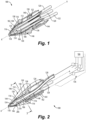
Fig. 1 is a cross-sectional perspective view of an embodiment of an air-data probe component constructed in accordance with the present disclosure, showing the additively manufactured inner member; -
Fig. 2 is a cross-sectional perspective view of the air-data probe component ofFig. 1 , showing the outer cover tip and temperature sensor; -
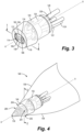
Fig. 3 is an axial end elevation cross-sectional perspective view of the air-data probe component ofFig. 1 , showing the pneumatic chambers; and -
Fig. 4 is a perspective view of the air-probe component ofFig. 1 , showing the flush, conformal, and continuous relationship of the outer cover tip with the aerodynamic outer surface of an aircraft. - Reference will now be made to the drawings wherein like reference numerals identify similar structural features or aspects of the subject disclosure. For purposes of explanation and illustration, and not limitation, a partial view of an embodiment of an air-data probe component in accordance with the disclosure is shown in
Fig. 1 and is designated generally byreference character 100. Other embodiments of systems in accordance with the disclosure, or aspects thereof, are provided inFigs. 2-4 , as will be described. The systems and methods described herein can be used to provide additively manufactured multi-function air-data probe components that are conformal/flush with the adjacent aircraft surface. - An air-
data probe component 100 includes an additively manufactured inner member 102. The inner member 102 includes integrally formed, monolithic structures including a mandrel bulkhead 104 defining a plurality ofpneumatic chambers Fig. 3 ) therein in fluid communication with an outer surface of themandrel bulkhead 116 throughrespective pressure ports Fig. 4 , where 200 is indicated as opposite port 201). The integrally formed, monolithic structures of the inner member 102 include a plurality ofpneumatic tubes Fig. 3 ), 126, 128 (labeled inFig. 2 ) extending aft of the mandrel bulkhead 104 along a probe axis A, each in fluid communication with a respective one of the plurality ofpneumatic chambers Fig. 2 , theouter surface 116 of the mandrel bulkhead 104 includes one ormore channels 130 defined therein configured to receive heater wire coils 132 therein wrapped around the mandrel bulkhead 104. - The plurality of
pneumatic chambers pitot chamber 106 in fluid communication with a forward facing one of thepressure ports 118, with respect to the probe axis A. Thechambers first chamber 108 is in fluid communication with a first lateral facing one of the pressure ports 202 (labeled inFig. 4 ) with respect to the probe axis A. Thesecond chamber 112 is in fluid communication with a second lateral facing one of the pressure ports 204 (labeled inFig. 4 ) with respect to the probe axis A, wherein the second lateral facing one of thepressure ports 204 is diametrically opposed to the first lateral facing one of thepressure ports 202 ofchamber 108 across the probe axis A. Athird chamber 110 is in fluid communication with a third lateral facing one of the pressure ports 201 (labeled inFig. 4 ) opening circumferentially spaced apart from the first and second lateral facing ones of thepressure ports chambers fourth chamber 114 is in fluid communication with a fourth lateral facing one of the pressure ports 200 (indicated inFig. 4 ) opening diametrically opposed to the third lateral facing one of thepressure ports 201 ofchamber 110 relative to the probe axis A. The pitot chamber includes a plurality ofdams 134, labeled inFigs. 1-2 , extending part way radially into thepitot chamber 106 to define a labyrinthine path through the pitot chamber for ice and moisture damming, wherein the plurality ofdams 134 are integral and monolithic with the mandrel bulkhead 104. There is also amoisture management port 206 labeled inFig. 2 for egress of moisture from thechamber 106. - The plurality of
pneumatic tubes Fig. 3 ), 126, 128 (labeled inFig. 2 ) includes a firstpneumatic tube 120 in fluid communication with thepitot chamber 106, a secondpneumatic tube 122 in fluid communication with thefirst AOA chamber 108, a thirdpneumatic tube 126 in fluid communication with thesecond AOA chamber 112, a fourthpneumatic tube 124 in fluid communication with thethird chamber 110, and a fifthpneumatic tube 128 in fluid communication with thesecond chamber 114. Thepneumatic tubes respective chambers Fig. 2 ) such as absolute or differential pressure transducers, for generating multi-function air-data probe data. Thepneumatic tubes necking section 138 that is radially narrower than the mandrel bulkhead 104 relative to the probe axis A. Abracer 140 is integrally formed and monolithic with thepneumatic tubes necking section 138. Thebracer 140 is radially wider than the mandrel bulkhead 104 and radially wider than thenecking section 138 relative to the probe axis A. Aft of thebracer 140, thepneumatic tubes - An
outer cover tip 144 is engaged about the mandrel bulkhead 104 with a plurality of bores 146 (labeled inFigs. 1, 2 , and4 ) therethrough for fluid communication of outside air pressure into thepneumatic tubes outer cover tip 144. Theouter cover tip 144 is not integrally formed with or monolithic with the inner member 102. An aft outer cover connector 148 outboard of thepneumatic tubes outer cover tip 144 to the aft manifold 142 to enclose the additively manufactured inner member 102 in an interior space bounded by theouter cover tip 144, the aft outer cover 148, and the manifold 142. - An
inner surface 150 of theouter cover tip 144 and theouter surface 116 of the mandrel bulkhead 104 conform to one another, enclosing coils of the heater wire 132 (labeled inFig. 2 ) seated thechannel 130 defined in theouter surface 116 of the mandrel bulkhead 104 between the mandrel bulkhead 104 and theouter cover tip 144. Anouter surface 152 of thebracer 140 conforms to and engages with theinner surface 150 of theouter cover tip 144. - Referring now to
Fig. 4 , theouter cover tip 144 includes a forward surface 154 and anaft surface 156 that is aft of the forward surface 154 along the probe axis A. Theaft surface 156 is stepped radially inward relative to the forward surface 154. The forward surface 154 is configured to be flush, conformal, and continuous with an aerodynamicouter surface 158 of the body of anaircraft 160. The aerodynamicouter surface 158 and theouter cover tip 144 are not integrally formed, monolithic structures with one another. The aerodynamicouter surface 158 and the additively manufactured inner member 102 (labeled inFigs. 1-3 ) are not integrally formed, monolithic structures with one another. Theouter cover tip 144 and the additively manufactured inner member 102 (labeled inFigs. 1-3 ) are not integrally formed, monolithic structures with one another. - Referring again to
Fig. 2 , theaft surface 156 is configured to extend inside the aerodynamicouter surface 158 of the aircraft 158 (labeled inFig. 4 ), for connecting the air-data probe component 100 internals, e.g., connecting thepressure transducers 136 of the air-data probe with aircraft systems for generating and communicating air-data, e.g., for use in control of theaircraft 158. Adata controller 166 is operatively connected to the plurality ofinternal sensors 136 and is configured to interface with an aircraft system, such as avionics of theaircraft 158 shown inFig. 4 , to communicate multi-function air-data to the aircraft system. Theouter cover tip 144 includes atemperature probe 162 seated in thewall 164 of theouter cover tip 144 that separates from an external environment and an interior space inside theouter cover tip 144 housing the mandrel bulkhead 104. Thetemperature probe 162 is also connected to thecontroller 166 for generating air data. - Systems and methods as disclosed herein provide potential benefits including the following. They can provide simplified production methods. They can also provide improved performance.
- The methods and systems of the present disclosure, as described above and shown in the drawings, provide for additively manufactured multi-function air-data probe components that are conformal/flush with the adjacent aircraft surface. While the apparatus and methods of the subject disclosure have been shown and described with reference to preferred embodiments, those skilled in the art will readily appreciate that changes and/or modifications may be made thereto without departing from the scope of the invention as defined by the claims.
Claims (15)
- An air-data probe component comprising:
an additively manufactured inner member (102) including integrally formed, monolithic structures including:a mandrel bulkhead (104) defining a plurality of pneumatic chambers (106, 108, 110, 112, 114) therein in fluid communication with an outer surface (116) of the mandrel bulkhead through respective pressure ports; anda plurality of pneumatic tubes (120, 122, 124, 126, 128) extending aft of the mandrel bulkhead along a probe axis, each in fluid communication with a respective one of the plurality of pneumatic chambers. - The air-data probe component as recited in claim 1, wherein the outer surface (116) of the mandrel bulkhead includes a channel (130) defined therein configured to receive heater wire coils (132) therein wrapped around the mandrel bulkhead.
- The air-data probe component as recited in claim 1 or 2, wherein the plurality of pneumatic chambers includes:a pitot chamber (106) in fluid communication with a forward facing one of the pressure ports, with respect to the probe axis;a first chamber (108) in fluid communication with a first lateral facing one of the pressure ports with respect to the probe axis;a second chamber (112) in fluid communication with a second lateral facing one of the pressure ports with respect to the probe axis, wherein the second lateral facing one of the pressure ports is diametrically opposed to the first lateral facing one of the pressure ports across the probe axis;a third chamber (110) in fluid communication with a third lateral facing one of the pressure ports opening circumferentially spaced apart from the first and second lateral facing ones of the pressure ports relative to the probe axis; anda fourth chamber (114) in fluid communication with a fourth lateral facing one of the pressure ports opening diametrically opposed to the third lateral facing one of the pressure ports relative to the probe axis, and optionally wherein the pitot chamber includes a plurality of dams extending part way radially into the pitot chamber defining a labyrinthine path through the pitot chamber for ice and moisture damming, wherein the plurality of dams are integral and monolithic with the mandrel bulkhead.
- The air-data probe component as recited in claim 3, wherein the plurality of pneumatic tubes includes:a first pneumatic tube (120) in fluid communication with the pitot chamber;a second pneumatic tube (122) in fluid communication with the first chamber;a third pneumatic tube (126) in fluid communication with the second chamber;a fourth pneumatic tube (124) in fluid communication with the third chamber; anda fifth pneumatic tube (128) in fluid communication with the fourth chamber; and optionally wherein the first, second, third, fourth, and fifth pneumatic tubes connect their respective chambers in fluid communication with one or more pressure transducers for generating multi-function air-data probe data.
- The air-data probe component as recited in claim 4, wherein the first, second, third, fourth, and fifth pneumatic tubes extend aft from the mandrel bulkhead along the probe axis through a necking section that is radially narrower than the mandrel bulkhead relative to the probe axis.
- The air-data probe component as recited in claim 5, further comprising a bracer (140) integral and monolithic with the first, second, third, fourth, and fifth pneumatic tubes aft of the necking section, wherein the bracer is radially wider than the mandrel bulkhead and radially wider than the necking section relative to the probe axis.
- The air-data probe component as recited in claim 6, wherein aft of the bracer, the first, second, third, fourth, and fifth pneumatic tubes diverge from one another and from the probe axis as they extend in an aft direction away from the mandrel bulkhead with respect to the probe axis and/or wherein aft of the bracer, aft ends of the first, second, third, fourth, and fifth pneumatic tubes are configured to be connected in fluid communication with one or more pressure transducers for generating multi-function air-data probe data.
- The air-data probe component as recited in claim 1, further comprising an outer cover tip (144) engaged about the mandrel bulkhead with a plurality of bores therethrough for fluid communication of outside air pressure into the plurality of pneumatic tubes through the outer cover tip, and optionally wherein an inner surface of the outer cover tip and an outer surface of the mandrel bulkhead conform to one another.
- The air-data probe component as recited in claim 8, further comprising a heater wire (132) seated in a channel (130) defined in the outer surface of the mandrel bulkhead, wherein coils of the heater wire are enclosed between the mandrel bulkhead and the outer cover tip.
- The air-data probe component as recited in claim 9, wherein the additively manufactured inner member includes a bracer (140) integrally formed and monolithic therewith, wherein the bracer extends outward from the plurality of pneumatic tubes relative to the probe axis, wherein an outer surface of the bracer conforms to and engages with an inner surface of the outer cover tip.
- The air-data probe component as recited in claim 8, wherein the outer cover tip includes a forward surface (154) (156) aft of the forward surface along the probe axis, wherein the forward surface is configured to be flush, conformal, and continuous with an aerodynamic outer surface of an aircraft, and wherein the aft surface is configured to extend inside the aerodynamic outer surface.
- The air-data probe component as recited in any of claims 8 to 11, wherein the outer cover tip includes a temperature probe (162) seated a in wall (164) of the outer cover tip that separates from an external environment and an interior space inside the outer cover tip housing the mandrel bulkhead.
- The air-data probe component as recited in any preceding claim, further comprising a plurality of internal sensors (136) in fluid communication with the plurality of pneumatic tubes for generating multi-function air-data, and optionally further comprising a data controller (166) operatively connected to the plurality of internal sensors and configured to interface with an aircraft system to communicate multi-function air-data to the aircraft system.
- An aircraft comprising:an aircraft body defining an aerodynamic outer surface; andan air-data probe including:
an additively manufactured inner member (102) including integrally formed, monolithic structures including:a mandrel bulkhead (104) defining a plurality of pneumatic chambers (106, 108, 110, 112, 114) therein in fluid communication with an outer surface (116) of the mandrel bulkhead through respective pressure ports;a plurality of pneumatic tubes (120, 122, 124, 126, 128) extending aft of the mandrel bulkhead along a probe axis, each in fluid communication with a respective one of the plurality of pneumatic chambers; andan outer cover tip (144) engaged about the mandrel bulkhead with a plurality of bores (146) therethrough for fluid communication of outside air pressure into the plurality of pneumatic tubes through the outer cover tip, wherein the outer cover tip includes a forward surface and an aft surface aft of the forward surface along the probe axis, wherein the forward surface is flush, conformal, and continuous with the aerodynamic outer surface, and wherein the aft surface is configured to extend inside the aircraft outer surface,wherein the aerodynamic outer surface and the outer cover tip are not integrally formed, monolithic structures with one another,wherein the aerodynamic outer surface and the additively manufactured inner member are not integrally formed, monolithic structures with one another, andwherein the outer cover tip and the additively manufactured inner member are not integrally formed, monolithic structures with one another. - The aircraft as recited in claim 14, wherein the plurality of pneumatic tubes connect their respective chambers in fluid communication with one or more pressure transducers (136) for generating multi-function air-data probe data.
Applications Claiming Priority (1)
| Application Number | Priority Date | Filing Date | Title |
|---|---|---|---|
| US18/235,188 US12455295B2 (en) | 2023-08-17 | 2023-08-17 | Conformal multi-function air-data probes |
Publications (1)
| Publication Number | Publication Date |
|---|---|
| EP4509842A1 true EP4509842A1 (en) | 2025-02-19 |
Family
ID=92424394
Family Applications (1)
| Application Number | Title | Priority Date | Filing Date |
|---|---|---|---|
| EP24194673.0A Pending EP4509842A1 (en) | 2023-08-17 | 2024-08-14 | Conformal multi-function air-data probes |
Country Status (2)
| Country | Link |
|---|---|
| US (1) | US12455295B2 (en) |
| EP (1) | EP4509842A1 (en) |
Citations (4)
| Publication number | Priority date | Publication date | Assignee | Title |
|---|---|---|---|---|
| US4836019A (en) * | 1987-08-27 | 1989-06-06 | Rosemount Inc. | Compact air data sensor |
| US20120118075A1 (en) * | 2010-11-15 | 2012-05-17 | Rosemount Aerospace Inc. | Static port apparatus |
| US20160280391A1 (en) * | 2015-03-23 | 2016-09-29 | Rosemount Aerospace Inc. | Air data probes |
| US20170052046A1 (en) * | 2015-08-20 | 2017-02-23 | Honeywell International Inc. | Systems and methods for additive manufacturing for air data probes |
Family Cites Families (18)
| Publication number | Priority date | Publication date | Assignee | Title |
|---|---|---|---|---|
| US5046360A (en) * | 1989-12-15 | 1991-09-10 | Rosemount Inc. | Aerodynamic probe internal constructions |
| US5601254A (en) | 1994-10-28 | 1997-02-11 | Rosemount Aerospace Inc. | Single sided backbone strut for air data sensor |
| US6609421B2 (en) | 2001-05-08 | 2003-08-26 | Rosemount Aerospace Inc. | Sideslip correction for a multi-function three probe air data system |
| US6604029B2 (en) | 2001-05-08 | 2003-08-05 | Rosemount Aerospace Inc. | Multi-function air data probes using neural network for sideslip compensation |
| US7379839B2 (en) | 2002-12-23 | 2008-05-27 | Rosemount Aerospace, Inc. | Multi-function air data probes employing neural networks for determining local air data parameters |
| US8680098B2 (en) | 2010-03-05 | 2014-03-25 | Janssen Pharmaceutica, Nv | Substituted aza-bicyclic imidazole derivatives useful as TRPM8 receptor modulators |
| US9279684B2 (en) | 2013-04-02 | 2016-03-08 | Rosemount Aerospace Inc. | Air data probe sense port repair |
| US20160304210A1 (en) | 2014-10-15 | 2016-10-20 | Rosemount Aerospace Inc. | One-piece air data probe |
| US10281303B2 (en) | 2015-03-23 | 2019-05-07 | Rosemount Aerospace, Inc. | Air data probe with improved performance at angle of attack operation |
| CA2919341C (en) | 2015-04-02 | 2022-11-15 | Rosemount Aerospace, Inc. | Corrosion-resistant heated air data probe |
| US9606137B2 (en) | 2015-06-17 | 2017-03-28 | Rosemount Aerospace Inc. | Enhancements for differential-pressure-driven fluid flows |
| CA3067810C (en) * | 2017-06-26 | 2022-07-26 | Dwyer Instruments, Inc. | Pitot tube instrument |
| CN109877314B (en) | 2018-12-05 | 2021-11-23 | 太原航空仪表有限公司 | Multifunctional atmospheric data probe and additive manufacturing method |
| US10884014B2 (en) | 2019-03-25 | 2021-01-05 | Rosemount Aerospace Inc. | Air data probe with fully-encapsulated heater |
| US11428707B2 (en) | 2019-06-14 | 2022-08-30 | Rosemount Aerospace Inc. | Air data probe with weld sealed insert |
| US11662235B2 (en) | 2021-10-01 | 2023-05-30 | Rosemount Aerospace Inc. | Air data probe with enhanced conduction integrated heater bore and features |
| US11624637B1 (en) | 2021-10-01 | 2023-04-11 | Rosemount Aerospace Inc | Air data probe with integrated heater bore and features |
| US12535499B2 (en) * | 2023-05-24 | 2026-01-27 | Rosemount Aerospace Inc. | Bulkheads and water dams for air data probes |
-
2023
- 2023-08-17 US US18/235,188 patent/US12455295B2/en active Active
-
2024
- 2024-08-14 EP EP24194673.0A patent/EP4509842A1/en active Pending
Patent Citations (4)
| Publication number | Priority date | Publication date | Assignee | Title |
|---|---|---|---|---|
| US4836019A (en) * | 1987-08-27 | 1989-06-06 | Rosemount Inc. | Compact air data sensor |
| US20120118075A1 (en) * | 2010-11-15 | 2012-05-17 | Rosemount Aerospace Inc. | Static port apparatus |
| US20160280391A1 (en) * | 2015-03-23 | 2016-09-29 | Rosemount Aerospace Inc. | Air data probes |
| US20170052046A1 (en) * | 2015-08-20 | 2017-02-23 | Honeywell International Inc. | Systems and methods for additive manufacturing for air data probes |
Also Published As
| Publication number | Publication date |
|---|---|
| US20250060389A1 (en) | 2025-02-20 |
| US12455295B2 (en) | 2025-10-28 |
Similar Documents
| Publication | Publication Date | Title |
|---|---|---|
| US11731782B2 (en) | Bulkheads for air data probes | |
| EP0073809B1 (en) | Pressure sensor for determining airspeed, altitude and angle of attack | |
| US4096744A (en) | Pressure sensor for determining airspeed, altitude and angle of attack | |
| EP0082874B1 (en) | Strut mounted multiple static tube | |
| US10018648B2 (en) | Systems, methods, and devices for fluid data sensing | |
| JP4100515B2 (en) | High-speed, wide-range flight speed vector measurement probe and measurement system | |
| KR100550882B1 (en) | Improvements to Multifunction Aircraft Probes | |
| CA2069110A1 (en) | Aerodynamic probe internal constructions | |
| US10564173B2 (en) | Pitot-static probe with pneumatic angle-of-attack sensor | |
| US12455295B2 (en) | Conformal multi-function air-data probes | |
| US10585109B2 (en) | Systems, methods, and devices for fluid data sensing | |
| US8433460B1 (en) | Onboard sensor suite for determining projectile velocity | |
| JP4241328B2 (en) | Air pressure barometric altimeter and its error correction method | |
| EP4575514A1 (en) | Bulkhead for air data probe | |
| CN115420256B (en) | Height measuring device, aircraft and height measuring system | |
| EP2527847A1 (en) | Aircraft wing and sensor | |
| EP2527846A1 (en) | Aircraft wing blister | |
| HK1035772B (en) | Improvements to multifunction aircraft probes |
Legal Events
| Date | Code | Title | Description |
|---|---|---|---|
| PUAI | Public reference made under article 153(3) epc to a published international application that has entered the european phase |
Free format text: ORIGINAL CODE: 0009012 |
|
| STAA | Information on the status of an ep patent application or granted ep patent |
Free format text: STATUS: THE APPLICATION HAS BEEN PUBLISHED |
|
| AK | Designated contracting states |
Kind code of ref document: A1 Designated state(s): AL AT BE BG CH CY CZ DE DK EE ES FI FR GB GR HR HU IE IS IT LI LT LU LV MC ME MK MT NL NO PL PT RO RS SE SI SK SM TR |
|
| STAA | Information on the status of an ep patent application or granted ep patent |
Free format text: STATUS: REQUEST FOR EXAMINATION WAS MADE |
|
| 17P | Request for examination filed |
Effective date: 20250819 |