EP4509791A1 - Plate heat exchanger - Google Patents
Plate heat exchanger Download PDFInfo
- Publication number
- EP4509791A1 EP4509791A1 EP24192741.7A EP24192741A EP4509791A1 EP 4509791 A1 EP4509791 A1 EP 4509791A1 EP 24192741 A EP24192741 A EP 24192741A EP 4509791 A1 EP4509791 A1 EP 4509791A1
- Authority
- EP
- European Patent Office
- Prior art keywords
- fluid
- heat exchanger
- fluid channel
- heat transfer
- plate
- Prior art date
- Legal status (The legal status is an assumption and is not a legal conclusion. Google has not performed a legal analysis and makes no representation as to the accuracy of the status listed.)
- Granted
Links
Images




Classifications
-
- F—MECHANICAL ENGINEERING; LIGHTING; HEATING; WEAPONS; BLASTING
- F28—HEAT EXCHANGE IN GENERAL
- F28D—HEAT-EXCHANGE APPARATUS, NOT PROVIDED FOR IN ANOTHER SUBCLASS, IN WHICH THE HEAT-EXCHANGE MEDIA DO NOT COME INTO DIRECT CONTACT
- F28D9/00—Heat-exchange apparatus having stationary plate-like or laminated conduit assemblies for both heat-exchange media, the media being in contact with different sides of a conduit wall
- F28D9/0093—Multi-circuit heat-exchangers, e.g. integrating different heat exchange sections in the same unit or heat-exchangers for more than two fluids
-
- F—MECHANICAL ENGINEERING; LIGHTING; HEATING; WEAPONS; BLASTING
- F28—HEAT EXCHANGE IN GENERAL
- F28F—DETAILS OF HEAT-EXCHANGE AND HEAT-TRANSFER APPARATUS, OF GENERAL APPLICATION
- F28F3/00—Plate-like or laminated elements; Assemblies of plate-like or laminated elements
- F28F3/08—Elements constructed for building-up into stacks, e.g. capable of being taken apart for cleaning
- F28F3/086—Elements constructed for building-up into stacks, e.g. capable of being taken apart for cleaning having one or more openings therein forming tubular heat-exchange passages
-
- F—MECHANICAL ENGINEERING; LIGHTING; HEATING; WEAPONS; BLASTING
- F28—HEAT EXCHANGE IN GENERAL
- F28D—HEAT-EXCHANGE APPARATUS, NOT PROVIDED FOR IN ANOTHER SUBCLASS, IN WHICH THE HEAT-EXCHANGE MEDIA DO NOT COME INTO DIRECT CONTACT
- F28D9/00—Heat-exchange apparatus having stationary plate-like or laminated conduit assemblies for both heat-exchange media, the media being in contact with different sides of a conduit wall
- F28D9/0031—Heat-exchange apparatus having stationary plate-like or laminated conduit assemblies for both heat-exchange media, the media being in contact with different sides of a conduit wall the conduits for one heat-exchange medium being formed by paired plates touching each other
- F28D9/0043—Heat-exchange apparatus having stationary plate-like or laminated conduit assemblies for both heat-exchange media, the media being in contact with different sides of a conduit wall the conduits for one heat-exchange medium being formed by paired plates touching each other the plates having openings therein for circulation of at least one heat-exchange medium from one conduit to another
- F28D9/005—Heat-exchange apparatus having stationary plate-like or laminated conduit assemblies for both heat-exchange media, the media being in contact with different sides of a conduit wall the conduits for one heat-exchange medium being formed by paired plates touching each other the plates having openings therein for circulation of at least one heat-exchange medium from one conduit to another the plates having openings therein for both heat-exchange media
-
- F—MECHANICAL ENGINEERING; LIGHTING; HEATING; WEAPONS; BLASTING
- F28—HEAT EXCHANGE IN GENERAL
- F28F—DETAILS OF HEAT-EXCHANGE AND HEAT-TRANSFER APPARATUS, OF GENERAL APPLICATION
- F28F13/00—Arrangements for modifying heat-transfer, e.g. increasing, decreasing
- F28F13/06—Arrangements for modifying heat-transfer, e.g. increasing, decreasing by affecting the pattern of flow of the heat-exchange media
- F28F13/08—Arrangements for modifying heat-transfer, e.g. increasing, decreasing by affecting the pattern of flow of the heat-exchange media by varying the cross-section of the flow channels
-
- F—MECHANICAL ENGINEERING; LIGHTING; HEATING; WEAPONS; BLASTING
- F28—HEAT EXCHANGE IN GENERAL
- F28F—DETAILS OF HEAT-EXCHANGE AND HEAT-TRANSFER APPARATUS, OF GENERAL APPLICATION
- F28F3/00—Plate-like or laminated elements; Assemblies of plate-like or laminated elements
- F28F3/08—Elements constructed for building-up into stacks, e.g. capable of being taken apart for cleaning
- F28F3/10—Arrangements for sealing the margins
-
- F—MECHANICAL ENGINEERING; LIGHTING; HEATING; WEAPONS; BLASTING
- F28—HEAT EXCHANGE IN GENERAL
- F28F—DETAILS OF HEAT-EXCHANGE AND HEAT-TRANSFER APPARATUS, OF GENERAL APPLICATION
- F28F2230/00—Sealing means
-
- F—MECHANICAL ENGINEERING; LIGHTING; HEATING; WEAPONS; BLASTING
- F28—HEAT EXCHANGE IN GENERAL
- F28F—DETAILS OF HEAT-EXCHANGE AND HEAT-TRANSFER APPARATUS, OF GENERAL APPLICATION
- F28F2270/00—Thermal insulation; Thermal decoupling
Definitions
- the present invention relates to a plate heat exchanger.
- a traditional plate heat exchanger comprises a plurality of heat transfer plates. Fluid channels used for two or more fluids are formed between adjacent heat transfer plates to conduct heat exchange between two or more fluids.
- a purpose of the embodiments of the present invention is to provide a plate heat exchanger, thereby such as improving the performance of the plate heat exchanger.
- An embodiment of the present invention provides a plate heat exchanger comprising: a plurality of heat transfer plates stacked in a first direction; first and second fluid channels formed between adjacent heat transfer plates and fluidly isolated from each other; and fluid barrier structure, which forms an isolation area in the first fluid channel so that the isolation area of the first fluid channel is fluidly isolated from the remaining areas of the first fluid channel.
- the fluid barrier structure is configured to surround the isolation area in the first fluid channel, or surround the isolation area in the first fluid channel together with an edge of the first fluid channel.
- the first fluid channel is configured to have two edge areas opposite to each other in a second direction perpendicular to the first direction
- the plate heat exchanger further comprises: two first ports formed in the heat transfer plate on two opposite sides of the heat transfer plate in the second direction, respectively, and fluidly communicated to the first fluid channel; and two first annular sealing portions formed on the heat transfer plate around the two first ports, and an outer periphery of each of the two first annular sealing portions is configured to have an outer peripheral portion proximate to in the second direction a middle of the heat transfer plate in the second direction
- the fluid barrier structure comprises a first fluid barrier structure that is disposed in the first fluid channel on a side of the outer peripheral portion of the outer periphery of one of the two first annular sealing portions far away from the other one of the two first annular sealing portions in the second direction so that a corresponding one of the two edge areas is formed as an isolation area.
- the second direction is a vertical direction and the corresponding one of the two edge areas of the first fluid channel is a bottom or top area of the first fluid channel in a state where the plate heat exchanger is being used.
- the fluid barrier structure further comprises a second fluid barrier structure that is disposed in the first fluid channel on a side of the outer peripheral portion of the outer periphery of the other one of the two first annular sealing portions far away from the one of the two first annular sealing portions in the second direction so that the corresponding other one of the two edge areas is formed as an isolation area.
- the second direction is a vertical direction
- the two edge areas of the first fluid channel are the bottom area and the top area of the first fluid channel, respectively, in a state where the plate heat exchanger is being used.
- the fluid barrier structure comprises a banded fluid barrier.
- the first fluid barrier structure comprises a banded fluid barrier.
- the fluid barrier comprises a barrier strip disposed between two adjacent heat transfer plates in the first fluid channel.
- the fluid barrier comprises two strip-shaped protrusions that protrude towards each other from two adjacent heat transfer plates defining the first fluid channel, respectively, and that are connected to each other.
- the fluid barrier comprises two strip-shaped protrusions that protrude towards each other from two adjacent heat transfer plates defining the first fluid channel, respectively; and a barrier strip disposed between the two strip-shaped protrusions of the two adjacent heat transfer plates in the first fluid channel.
- a width of a top of the strip-shaped protrusion is in a range from 0.5 to 50 mm.
- a width of a top of the strip-shaped protrusion is in a range from 0.5 to 50 mm.
- At least one portion of the fluid barrier is configured to have a linear shape.
- the at least one portion of the fluid barrier is at an angle of 80-90 degrees relative to the second direction.
- the strip-shaped protrusion is configured to have a cross section of a circle, triangle, or trapezoid.
- the strip-shaped protrusion is configured to have a cross section of a circle, triangle, or trapezoid.
- a top of the strip-shaped protrusion is configured to have a recess.
- a top of the strip-shaped protrusion is configured to have a recess.
- the fluid barrier comprises a portion partially surrounding the one of the two first annular sealing portions.
- the plate heat exchanger is positioned such that the second direction is the vertical direction, and an upper edge of the first fluid barrier structure is lower than a bottom outer peripheral portion of the outer periphery of the one of the two first annular sealing portions, or the upper edge of the first fluid barrier structure is aligned with the bottom outer peripheral portion of the outer periphery of the one of the two first annular sealing portions in the second direction in a state where the plate heat exchanger is being used.
- the plate heat exchanger is positioned such that the second direction is the vertical direction
- the fluid barrier comprises a portion partially surrounding the one of the two first annular sealing portions and a portion with an upper edge higher than the bottom outer peripheral portion of the outer periphery of the one of the two first annular sealing portions in a state where the plate heat exchanger is being used.
- the plate heat exchanger further comprises: a third fluid channel formed between the adjacent heat transfer plates and fluidly isolated from the first and second fluid channels; two second ports formed in the heat transfer plate on two opposite sides of the heat transfer plate in the second direction, respectively, and fluidly communicated to the second fluid channel; and two third ports formed in the heat transfer plate on two opposite sides of the heat transfer plate in the second direction, respectively, and fluidly communicated to the third fluid channel.
- the plate heat exchanger further comprises: a third fluid channel formed between the adjacent heat transfer plates and fluidly isolated from the first and second fluid channels; two second ports formed in the heat transfer plate on two opposite sides of the heat transfer plate in the second direction, respectively, and fluidly communicated to the second fluid channel; two second annular sealing portions formed on the heat transfer plate around the two second ports, respectively; two third ports formed in the heat transfer plate on two opposite sides of the heat transfer plate in the second direction, respectively, and fluidly communicated to the third fluid channel; and two third annular sealing portions formed on the heat transfer plate around the two third ports, respectively; wherein the plate heat exchanger is positioned such that the second direction is the vertical direction, and the fluid barrier comprises a portion partially surrounding the one of the two first annular sealing portions, a portion partially surrounding a corresponding one of the two second annular sealing portions, a portion partially surrounding a corresponding one of the two third annular sealing portions, and a portion with an upper edge higher than a bottom outer peripheral portion of the outer peripher
- the plate heat exchanger further comprises: a discharge hole formed in the heat transfer plate in the second direction on the side of the fluid barrier away from the other one of the two first annular sealing portions and being in fluid communication with the first fluid channel and fluid isolation from the second fluid channel.
- the plate heat exchanger further comprises: a third fluid channel formed between the adjacent heat transfer plates and fluidly isolated from the first and second fluid channels; two second ports formed in the heat transfer plate on two opposite sides of the heat transfer plate in the second direction, respectively, and fluidly communicated to the second fluid channel; two third ports formed in the heat transfer plate on two opposite sides of the heat transfer plate in the second direction, respectively, and fluidly communicated to the third fluid channel; and a discharge hole formed in the heat transfer plate in the second direction on the side of the fluid barrier away from the other one of the two first annular sealing portions and being in fluid communication with the first fluid channel and fluid isolation from the second and third fluid channels.
- the fluid barrier structure comprises a filling material.
- the plate heat exchanger further comprises: two strip-shaped recesses that are recessed in a direction away from each other from two adjacent heat transfer plates defining the second fluid channel, respectively, and wherein the strip-shaped recesses of two adjacent heat transfer plates form a guiding channel.
- the plate heat exchanger further comprises: a strip-shaped recess formed by the strip-shaped protrusion of the heat transfer plate in the second fluid channel, and wherein the strip-shaped recesses of two adjacent heat transfer plates form a guiding channel.
- the plate heat exchanger further comprises: a strip-shaped recess formed by the strip-shaped protrusion of the heat transfer plate in the second fluid channel, and wherein the strip-shaped recesses of two adjacent heat transfer plates form a guiding channel.
- At least one portion of the guiding channel is configured to have a linear shape.
- the at least one portion of the guiding channel is at an angle of 80-90 degrees relative to the second direction.
- the guiding channel comprises a plurality of guiding channels arranged in the second direction.
- the strip-shaped recess is configured to have a plurality of portions with different widths.
- the performance of the plate heat exchanger may be improved, for example, the anti-freezing performance of the plate heat exchanger may be enhanced.
- a plate heat exchanger 100 comprises: a plurality of heat transfer plates 2 stacked in a first direction D1; first and second fluid channels 11, 12 formed between adjacent heat transfer plates 2 and fluidly isolated from each other; and a fluid barrier structure 4, which forms an isolation area in a first fluid channel 11 so that the isolation area of the first fluid channel 11 is fluidly isolated from the remaining areas of the first fluid channel 11.
- the fluid barrier structure 4 is configured to surround the isolation area in the first fluid channel 11, or surround the isolation area in the first fluid channel 11 together with an edge of the first fluid channel 11.
- the fluid barrier structure 4 may comprise a filling material 48.
- the first fluid channel 11 is configured to have two edge areas or end areas 110 opposite to each other in a second direction D2 perpendicular to the first direction D 1.
- the plate heat exchanger 100 further comprises: two first ports 31, which are formed in the heat transfer plate 2 on opposite sides of the heat transfer plate 2 in the second direction D2, and are fluidly communicated to the first fluid channel 11; and two first annular sealing portions 310 formed on the heat transfer plate 2 around the two first ports 31 respectively, and an outer periphery 311 of each of the two first annular sealing portions 310 is configured to have an outer peripheral portion 312 proximate to a middle of the heat transfer plate 2 in the second direction D2.
- the fluid barrier structure 4 comprises a first fluid barrier structure 4, which is disposed in the first fluid channel 11 on a side of the outer peripheral portion 312 of the outer periphery 311 of one of the two first annular sealing portions 310 far away from the other one of the two first annular sealing portions 310 in the second direction D2 so that a corresponding one of the two edge areas 110 is formed as an isolation area.
- the plate heat exchanger 100 further comprises: a third fluid channel 13 formed between adjacent heat transfer plates 2 and fluidly isolated from the first and second fluid channels 11, 12; two second ports 32 formed in the heat transfer plate 2 on two opposite sides of the heat transfer plate 2 in the second direction D2, respectively, and fluidly communicated to the second fluid channel 12; two second annular sealing portions formed on the heat transfer plate 2 around the two second ports 32, respectively; two third ports 33 formed in the heat transfer plate 2 on two opposite sides of the heat transfer plate 2 in the second direction D2, respectively, and fluidly communicated to the third fluid channel 13; and two third annular sealing portions formed on the heat transfer plate 2 around the two third ports 33, respectively.
- the first annular sealing portion 310 formed on the heat transfer plate 2 around the first port 31 fluidly isolates the second fluid channel 12 and the third fluid channel 13 from the first port 31, thereby the first port 31 is only fluidly communicated to the first fluid channel 11.
- the second annular sealing portion formed on the heat transfer plate 2 around the second port 32 fluidly isolates the first fluid channel 11 and the third fluid channel 13 from the second port 32, thereby the second port 32 is only fluidly communicated to the second fluid channel 12.
- the third annular sealing portion formed on the heat transfer plate 2 around the third port 33 fluidly isolates the second fluid channel 12 and the third fluid channel 13 from the third port 33, thus the third port 33 is only fluidly communicated to the third fluid channel 13.
- the first fluid channel 11 is used for a first heat exchange medium
- the second fluid channel 12 is used for a second heat exchange medium
- the third fluid channel 13 is used for a third heat exchange medium.
- the first heat exchange medium may be liquids such as water, ethylene glycol, propylene glycol, etc.
- the second and third heat exchange media may be refrigerant.
- the first heat exchange medium may also be refrigerant.
- Plate heat exchanger 100 may be a soft brazed plate heat exchanger, a hard brazed plate heat exchanger, a gasket plate heat exchanger, or any other types of plate heat exchangers.
- the plate heat exchanger 100 may also comprise a cover plate 71 and a bottom plate 72, and the plurality of heat transfer plates 2 are disposed between the cover plate 71 and the bottom plate 72.
- the plate heat exchanger 100 may be the heat exchanger shown in FIGS.1 , 8-14 , or the heat exchanger shown in FIG.15 , or other types of plate heat exchangers.
- Plate heat exchanger 100 may also be a double-wall heat exchanger.
- the second direction D2 is a vertical direction and the corresponding one of the two edge areas 110 of the first fluid channel 11, which is formed as the isolation area, is a bottom or top area of the first fluid channel 11 in a state where the plate heat exchanger 100 is being used.
- the fluid barrier structure 4 further comprises a second fluid barrier structure 4, which is disposed in the first fluid channel 11 on a side of the outer peripheral portion 312 of the outer periphery 311 of the other one of the two first annular sealing portions 310 far away from the one of the two first annular sealing portions 310 in the second direction D2 so that the corresponding other one of the two edge areas 110 is formed as an isolation area.
- the second fluid barrier structure 4 and the first fluid barrier structure 4 may be the same fluid barrier structure.
- the second direction D2 is a vertical direction, and the two edge areas 110 of the first fluid channel 11 are the bottom area and the top area of the first fluid channel 11, respectively, in a state where the plate heat exchanger 100 is being used.
- the fluid barrier structure 4 or the first fluid barrier structure 4 comprises a banded fluid barrier 47.
- the fluid barrier 47 comprises a barrier strip 41 disposed between two adjacent heat transfer plates 2 in the first fluid channel 11.
- the fluid barrier 47 comprises two strip-shaped protrusions 42 that protrude towards each other from two adjacent heat transfer plates 2 defining the first fluid channel 11, respectively, and that are connected to each other. Referring to FIG.
- the fluid barrier 47 comprises two strip-shaped protrusions 42 that protrude towards each other from two adjacent heat transfer plates 2 defining the first fluid channel 11, respectively; and a barrier strip 41 disposed between the two strip-shaped protrusions 42 of the two adjacent heat transfer plates 2 in the first fluid channel 11.
- a width Tp of a top 420 of the strip-shaped protrusion 42 may be in the range from 0.5 to 50 mm, 0.5 to 10 mm, or 1 to 3 mm, or other suitable dimensions.
- a width of the barrier strip 41 may be greater than, less than, or equal to the width Tp of the top 420 of the strip-shaped protrusion 42.
- the width of the top 420 of the strip-shaped protrusion 42 may vary along a length of the strip-shaped protrusion 42, such as being wider and/or narrower in some portions of the length of the strip-shaped protrusion 42, as long as it may block the fluid in the first fluid channel 11.
- a material of the barrier strip 41 may be the same as or different from that of the heat transfer plate 2.
- the strip-shaped protrusion 42 may have a cross section of a circle, triangle, or trapezoid, or any other suitable shapes, as long as it may block the fluid in the first fluid channel 11.
- the top 420 of the strip-shaped protrusion 42 may have a recess 421. As a result, a solder may be kept in the recess 421.
- the fluid barrier 47 comprises the strip-shaped protrusion 42 and the barrier strip 41
- the fluid barrier 47 may only comprise the barrier strip 41.
- At least one portion of the fluid barrier 47 is configured to have a linear shape.
- the at least one portion of the fluid barrier 47 is at an angle of 80-90 degrees relative to the second direction D2.
- the fluid barrier 47 may have a linear shape, and the fluid barrier 47 may at an angle of 80-90 degrees relative to the second direction D2.
- the fluid barrier 47 may have a wavy shape, a broken line shape, or other suitable shapes in length, in addition to the linear shape.
- the plate heat exchanger 100 is positioned such that the second direction D2 is the vertical direction, and an upper edge 40 of the first fluid barrier structure 4 is lower than a bottom outer peripheral portion 313 of the outer periphery 311 of the one of the two first annular sealing portions 310, or the upper edge 40 of the first fluid barrier structure 4 is aligned with the bottom outer peripheral portion 313 of the outer periphery 311 of the one of the two first annular sealing portions 310 in the second direction D2 in a state where the plate heat exchanger 100 is being used.
- the fluid barrier 47 may be horizontal or inclined. Referring to FIG.
- a lower edge of the first fluid barrier structure 4 may be aligned with a top outer peripheral portion 314 of the outer periphery 311 of the other one of the two first annular sealing portions 310 in the second direction D2.
- the lower edge of the first fluid barrier structure 4 may be higher or lower than the top outer peripheral portion 314.
- the plate heat exchanger 100 further comprises two strip-shaped recesses 49 that are recessed in a direction away from each other from two adjacent heat transfer plates defining the second fluid channel 12 or each of the second fluid channel 12 and the third fluid channel 13, respectively, and the strip-shaped recesses 49 of the two adjacent heat transfer plates 2 form a guiding channel 6.
- the plate heat exchanger 100 also comprises a strip-shaped recess 49 formed by the strip-shaped protrusion 42 of the heat transfer plate 2 in the second fluid channel 12 or in each of the second fluid channel 12 and the third fluid channel 13, and the strip-shaped recesses 49 of two adjacent heat transfer plates 2 form a guiding channel 6.
- At least one portion of guiding channel 6 may have a linear shape.
- the at least one portion of the guiding channel 6 may be at an angle of 80-90 degrees relative to the second direction. Therefore, the heat exchange medium (such as refrigerant) in the second fluid channel 12 or in each of the second fluid channel 12 and the third fluid channel 13 may flow in the guiding channel 6.
- the width of the top 420 of the strip-shaped protrusion 42 may vary along the length of the strip-shaped protrusion 42, such as being wider and/or narrower in some portions of the length of the strip-shaped protrusion 42. That is, the strip-shaped recess 49 has a plurality of portions with different widths.
- the guiding channel 6 comprises a plurality of guiding channels 6 arranged in the second direction D2, such as two, three, or more guiding channels 6.
- the cross sections of the plurality of guiding channels 6 may be the same or different.
- the fluid barrier 47 comprises a portion 43 partially surrounding the one of the two first annular sealing portions 310.
- the plate heat exchanger 100 is positioned such that the second direction D2 is the vertical direction, and the fluid barrier 47 comprises a portion 43 partially surrounding the one of the two first annular sealing portions 310 and a portion 44 with an upper edge 40 higher than the bottom outer peripheral portion 313 of the outer periphery 311 of the one of the two first annular sealing portions 310 in a state where the plate heat exchanger 100 is being used.
- the fluid barrier 47 comprises a portion 43 partially surrounding the one of the two first annular sealing portions 310, a portion 45 partially surrounding a corresponding one of the two second annular sealing portions, a portion 46 partially surrounding a corresponding one of the two third annular sealing portions, and a portion 44 with an upper edge 40 higher than the bottom outer peripheral portion 313 of the outer periphery 311 of the one of the two first annular sealing portions 310.
- the plate heat exchanger 100 further comprises a discharge hole 5 formed in the heat transfer plate 2 on the side of the fluid barrier 47 away from the other one of the two first annular sealing portions 310 in the second direction D2, which is in fluid communication with the first fluid channel 11 and fluid isolation from the second fluid channel 12.
- a discharge hole 5 formed in the heat transfer plate 2 on the side of the fluid barrier 47 away from the other one of the two first annular sealing portions 310 in the second direction D2, which is in fluid communication with the first fluid channel 11 and fluid isolation from the second fluid channel 12.
- the plate heat exchanger 100 may comprise one or more discharge holes 5, which may be used for leak detection in production lines or applications. In the production process, if the fluid barrier fails, the heat exchange medium may flow into the edge area, causing freezing problems during use. Therefore, the fault may be checked through the discharge hole, which may be connected to an application pipeline system or covered with an insulation material during application.
- the fluid barrier structure 4 is disposed in the first fluid channel 11, the fluid barrier structure 4 may also be disposed in at least one of the second fluid channel 12 and the third fluid channel 13, or disposed in each of the first fluid channel 11, second fluid channel 12, and third fluid channel 13.
- the area and size of the fluid barrier structure 4 in each of the fluid channels may be the same or different. For example, in some fluid channels, the fluid barrier is narrower, while in other fluid channels, the fluid barrier is wider.
- the first fluid barrier structure 4 comprises a filling material 48.
- the filling material 48 comprises solid material or liquid material that is then cured.
- an adhesive is filled in the edge area 110 (top and/or bottom area) of at least one of the first fluid channel 11, second fluid channel 12, and third fluid channel 13 to provide a blocking effect.
- the adhesive may be epoxy resin.
- the filling material 48 may also be low melting point metal or alloy, oil, wax, plastic, or any type of liquid.
- the fluid barrier structure 4 is disposed in the bottom area of the first fluid channel 11, when the heat exchange medium (such as water) is discharged from the first fluid channel 11 in case of the plate heat exchanger 100 being not used (such as in winter or at low ambient temperatures), there is less heat exchange medium remained in the bottom area of the first fluid channel 11, or there is no heat exchange medium remained in the bottom area of the first fluid channel 11, thereby avoiding freezing or static freezing at low temperatures.
- the heat exchange medium such as water
- the heat transfer medium such as refrigerant
- the heat transfer medium is more uniformly distributed, especially for plate heat exchangers with larger widths (the dimensions in a third direction perpendicular to the first and second directions).
- the fluid barrier structure 4 is disposed in the first fluid channel 11, which may avoid dynamic freezing during the heat transfer.
- setting the fluid barrier structure 4 in the edge area 110 (bottom and/or top area) of the first fluid channel 11 does not have a negative impact on a heat transfer efficiency, but may reduce an amount of the heat transfer medium (such as refrigerant) filled therein.
- the formation of the isolation area in fluid channels through the fluid barrier structure may reduce the amount of the heat transfer medium (such as refrigerant) filled therein.
- the fluid barrier structure is disposed in the heat transfer plate without any additional cost or process, which is easy to be implemented on a product.
- the strip-shaped protrusion 42 of the fluid barrier structure is disposed in the first fluid channel 11 and the guiding channel 6 is formed in the second fluid channel 12, thereby improving the heat transfer efficiency and compensating for a decrease in a heat transfer area.
- the fluid barrier structure has no impact on the user.
Landscapes
- Engineering & Computer Science (AREA)
- Physics & Mathematics (AREA)
- Thermal Sciences (AREA)
- Mechanical Engineering (AREA)
- General Engineering & Computer Science (AREA)
- Heat-Exchange Devices With Radiators And Conduit Assemblies (AREA)
Abstract
Description
- This application claims the priority of Chinese Patent Applications No.
CN 202311042633.4 CN202322218673.1 filed on August 17, 2023 - The present invention relates to a plate heat exchanger.
- A traditional plate heat exchanger comprises a plurality of heat transfer plates. Fluid channels used for two or more fluids are formed between adjacent heat transfer plates to conduct heat exchange between two or more fluids.
- A purpose of the embodiments of the present invention is to provide a plate heat exchanger, thereby such as improving the performance of the plate heat exchanger.
- An embodiment of the present invention provides a plate heat exchanger comprising: a plurality of heat transfer plates stacked in a first direction; first and second fluid channels formed between adjacent heat transfer plates and fluidly isolated from each other; and fluid barrier structure, which forms an isolation area in the first fluid channel so that the isolation area of the first fluid channel is fluidly isolated from the remaining areas of the first fluid channel.
- According to an embodiment of the present invention, the fluid barrier structure is configured to surround the isolation area in the first fluid channel, or surround the isolation area in the first fluid channel together with an edge of the first fluid channel.
- According to an embodiment of the present invention, the first fluid channel is configured to have two edge areas opposite to each other in a second direction perpendicular to the first direction, the plate heat exchanger further comprises: two first ports formed in the heat transfer plate on two opposite sides of the heat transfer plate in the second direction, respectively, and fluidly communicated to the first fluid channel; and two first annular sealing portions formed on the heat transfer plate around the two first ports, and an outer periphery of each of the two first annular sealing portions is configured to have an outer peripheral portion proximate to in the second direction a middle of the heat transfer plate in the second direction, and wherein the fluid barrier structure comprises a first fluid barrier structure that is disposed in the first fluid channel on a side of the outer peripheral portion of the outer periphery of one of the two first annular sealing portions far away from the other one of the two first annular sealing portions in the second direction so that a corresponding one of the two edge areas is formed as an isolation area.
- According to an embodiment of the present invention, the second direction is a vertical direction and the corresponding one of the two edge areas of the first fluid channel is a bottom or top area of the first fluid channel in a state where the plate heat exchanger is being used.
- According to an embodiment of the present invention, the fluid barrier structure further comprises a second fluid barrier structure that is disposed in the first fluid channel on a side of the outer peripheral portion of the outer periphery of the other one of the two first annular sealing portions far away from the one of the two first annular sealing portions in the second direction so that the corresponding other one of the two edge areas is formed as an isolation area.
- According to an embodiment of the present invention, the second direction is a vertical direction, and the two edge areas of the first fluid channel are the bottom area and the top area of the first fluid channel, respectively, in a state where the plate heat exchanger is being used.
- According to an embodiment of the present invention, the fluid barrier structure comprises a banded fluid barrier.
- According to an embodiment of the present invention, the first fluid barrier structure comprises a banded fluid barrier.
- According to an embodiment of the present invention, the fluid barrier comprises a barrier strip disposed between two adjacent heat transfer plates in the first fluid channel.
- According to an embodiment of the present invention, the fluid barrier comprises two strip-shaped protrusions that protrude towards each other from two adjacent heat transfer plates defining the first fluid channel, respectively, and that are connected to each other.
- According to an embodiment of the present invention, the fluid barrier comprises two strip-shaped protrusions that protrude towards each other from two adjacent heat transfer plates defining the first fluid channel, respectively; and a barrier strip disposed between the two strip-shaped protrusions of the two adjacent heat transfer plates in the first fluid channel.
- According to an embodiment of the present invention, a width of a top of the strip-shaped protrusion is in a range from 0.5 to 50 mm.
- According to an embodiment of the present invention, a width of a top of the strip-shaped protrusion is in a range from 0.5 to 50 mm.
- According to an embodiment of the present invention, at least one portion of the fluid barrier is configured to have a linear shape.
- According to an embodiment of the present invention, the at least one portion of the fluid barrier is at an angle of 80-90 degrees relative to the second direction.
- According to an embodiment of the present invention, the strip-shaped protrusion is configured to have a cross section of a circle, triangle, or trapezoid.
- According to an embodiment of the present invention, the strip-shaped protrusion is configured to have a cross section of a circle, triangle, or trapezoid.
- According to an embodiment of the present invention, a top of the strip-shaped protrusion is configured to have a recess.
- According to an embodiment of the present invention, a top of the strip-shaped protrusion is configured to have a recess.
- According to an embodiment of the present invention, the fluid barrier comprises a portion partially surrounding the one of the two first annular sealing portions.
- According to an embodiment of the present invention, the plate heat exchanger is positioned such that the second direction is the vertical direction, and an upper edge of the first fluid barrier structure is lower than a bottom outer peripheral portion of the outer periphery of the one of the two first annular sealing portions, or the upper edge of the first fluid barrier structure is aligned with the bottom outer peripheral portion of the outer periphery of the one of the two first annular sealing portions in the second direction in a state where the plate heat exchanger is being used.
- According to an embodiment of the present invention, the plate heat exchanger is positioned such that the second direction is the vertical direction, and the fluid barrier comprises a portion partially surrounding the one of the two first annular sealing portions and a portion with an upper edge higher than the bottom outer peripheral portion of the outer periphery of the one of the two first annular sealing portions in a state where the plate heat exchanger is being used.
- According to an embodiment of the present invention, the plate heat exchanger further comprises: a third fluid channel formed between the adjacent heat transfer plates and fluidly isolated from the first and second fluid channels; two second ports formed in the heat transfer plate on two opposite sides of the heat transfer plate in the second direction, respectively, and fluidly communicated to the second fluid channel; and two third ports formed in the heat transfer plate on two opposite sides of the heat transfer plate in the second direction, respectively, and fluidly communicated to the third fluid channel.
- According to an embodiment of the present invention, the plate heat exchanger further comprises: a third fluid channel formed between the adjacent heat transfer plates and fluidly isolated from the first and second fluid channels; two second ports formed in the heat transfer plate on two opposite sides of the heat transfer plate in the second direction, respectively, and fluidly communicated to the second fluid channel; two second annular sealing portions formed on the heat transfer plate around the two second ports, respectively; two third ports formed in the heat transfer plate on two opposite sides of the heat transfer plate in the second direction, respectively, and fluidly communicated to the third fluid channel; and two third annular sealing portions formed on the heat transfer plate around the two third ports, respectively; wherein the plate heat exchanger is positioned such that the second direction is the vertical direction, and the fluid barrier comprises a portion partially surrounding the one of the two first annular sealing portions, a portion partially surrounding a corresponding one of the two second annular sealing portions, a portion partially surrounding a corresponding one of the two third annular sealing portions, and a portion with an upper edge higher than a bottom outer peripheral portion of the outer periphery of the one of the two first annular sealing portions in a state where the plate heat exchanger is being used.
- According to an embodiment of the present invention, the plate heat exchanger further comprises: a discharge hole formed in the heat transfer plate in the second direction on the side of the fluid barrier away from the other one of the two first annular sealing portions and being in fluid communication with the first fluid channel and fluid isolation from the second fluid channel.
- According to an embodiment of the present invention, the plate heat exchanger further comprises: a third fluid channel formed between the adjacent heat transfer plates and fluidly isolated from the first and second fluid channels; two second ports formed in the heat transfer plate on two opposite sides of the heat transfer plate in the second direction, respectively, and fluidly communicated to the second fluid channel; two third ports formed in the heat transfer plate on two opposite sides of the heat transfer plate in the second direction, respectively, and fluidly communicated to the third fluid channel; and a discharge hole formed in the heat transfer plate in the second direction on the side of the fluid barrier away from the other one of the two first annular sealing portions and being in fluid communication with the first fluid channel and fluid isolation from the second and third fluid channels.
- According to an embodiment of the present invention, the fluid barrier structure comprises a filling material.
- According to an embodiment of the present invention, the plate heat exchanger further comprises: two strip-shaped recesses that are recessed in a direction away from each other from two adjacent heat transfer plates defining the second fluid channel, respectively, and wherein the strip-shaped recesses of two adjacent heat transfer plates form a guiding channel.
- According to an embodiment of the present invention, the plate heat exchanger further comprises: a strip-shaped recess formed by the strip-shaped protrusion of the heat transfer plate in the second fluid channel, and wherein the strip-shaped recesses of two adjacent heat transfer plates form a guiding channel.
- According to an embodiment of the present invention, the plate heat exchanger further comprises: a strip-shaped recess formed by the strip-shaped protrusion of the heat transfer plate in the second fluid channel, and wherein the strip-shaped recesses of two adjacent heat transfer plates form a guiding channel.
- According to an embodiment of the present invention, at least one portion of the guiding channel is configured to have a linear shape.
- According to an embodiment of the present invention, the at least one portion of the guiding channel is at an angle of 80-90 degrees relative to the second direction.
- According to an embodiment of the present invention, the guiding channel comprises a plurality of guiding channels arranged in the second direction.
- According to an embodiment of the present invention, the strip-shaped recess is configured to have a plurality of portions with different widths.
- By adopting the plate heat exchanger according to an embodiment of the present invention, the performance of the plate heat exchanger may be improved, for example, the anti-freezing performance of the plate heat exchanger may be enhanced.
-
-
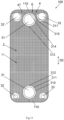
FIG. 1 is a schematic front view of a plate heat exchanger according to an embodiment of the present invention. -
FIGS. 2 to 5 shows various schematic cross-sectional views of the strip-shaped protrusions of a heat transfer plate of a plate heat exchanger. -
FIG. 6 is a schematic partial enlarged cross-sectional view of a plate heat exchanger according to an embodiment of the present invention. -
FIG. 7 is a schematic partial enlarged cross-sectional view of a plate heat exchanger according to an embodiment of the present invention. -
FIG. 8 is a schematic front view of a plate heat exchanger according to an embodiment of the present invention. -
FIG. 9 is a schematic front view of a plate heat exchanger according to an embodiment of the present invention. -
FIG. 10 is a schematic front view of a plate heat exchanger according to an embodiment of the present invention. -
FIG. 11 is a schematic front view of a plate heat exchanger according to an embodiment of the present invention. -
FIG. 12 is a schematic front view of a plate heat exchanger according to an embodiment of the present invention. -
FIG. 13 is a schematic front view of a plate heat exchanger according to an embodiment of the present invention. -
FIG. 14 is a schematic front view of a plate heat exchanger according to an embodiment of the present invention. -
FIG. 15 is a schematic front view of a plate heat exchanger according to an embodiment of the present invention. -
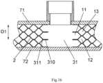
FIG. 16 is a schematic cross-sectional view of a plate heat exchanger according to an embodiment of the present invention. - The present invention will be described below in further detail in conjunction with the drawings and specific embodiments.
- Referring to
FIGS. 1 to 16 , aplate heat exchanger 100 according to an embodiment of the present invention comprises: a plurality ofheat transfer plates 2 stacked in a first direction D1; first andsecond fluid channels heat transfer plates 2 and fluidly isolated from each other; and afluid barrier structure 4, which forms an isolation area in afirst fluid channel 11 so that the isolation area of thefirst fluid channel 11 is fluidly isolated from the remaining areas of thefirst fluid channel 11. For example, thefluid barrier structure 4 is configured to surround the isolation area in thefirst fluid channel 11, or surround the isolation area in thefirst fluid channel 11 together with an edge of thefirst fluid channel 11. Thefluid barrier structure 4 may comprise a fillingmaterial 48. - Referring to
FIGS. 1 to 16 , in an embodiment according to the present invention, thefirst fluid channel 11 is configured to have two edge areas or endareas 110 opposite to each other in a second direction D2 perpendicular to the first direction D 1. Theplate heat exchanger 100 further comprises: twofirst ports 31, which are formed in theheat transfer plate 2 on opposite sides of theheat transfer plate 2 in the second direction D2, and are fluidly communicated to thefirst fluid channel 11; and two firstannular sealing portions 310 formed on theheat transfer plate 2 around the twofirst ports 31 respectively, and anouter periphery 311 of each of the two firstannular sealing portions 310 is configured to have an outerperipheral portion 312 proximate to a middle of theheat transfer plate 2 in the second direction D2. Thefluid barrier structure 4 comprises a firstfluid barrier structure 4, which is disposed in thefirst fluid channel 11 on a side of the outerperipheral portion 312 of theouter periphery 311 of one of the two firstannular sealing portions 310 far away from the other one of the two firstannular sealing portions 310 in the second direction D2 so that a corresponding one of the twoedge areas 110 is formed as an isolation area. - Referring to
FIGS. 1 ,8-14 , in an embodiment of the present invention, theplate heat exchanger 100 further comprises: a thirdfluid channel 13 formed between adjacentheat transfer plates 2 and fluidly isolated from the first and secondfluid channels second ports 32 formed in theheat transfer plate 2 on two opposite sides of theheat transfer plate 2 in the second direction D2, respectively, and fluidly communicated to thesecond fluid channel 12; two second annular sealing portions formed on theheat transfer plate 2 around the twosecond ports 32, respectively; twothird ports 33 formed in theheat transfer plate 2 on two opposite sides of theheat transfer plate 2 in the second direction D2, respectively, and fluidly communicated to the thirdfluid channel 13; and two third annular sealing portions formed on theheat transfer plate 2 around the twothird ports 33, respectively. - According to an embodiment of the present invention, as shown in
FIG. 16 , the firstannular sealing portion 310 formed on theheat transfer plate 2 around thefirst port 31 fluidly isolates thesecond fluid channel 12 and the thirdfluid channel 13 from thefirst port 31, thereby thefirst port 31 is only fluidly communicated to thefirst fluid channel 11. The second annular sealing portion formed on theheat transfer plate 2 around thesecond port 32 fluidly isolates thefirst fluid channel 11 and the thirdfluid channel 13 from thesecond port 32, thereby thesecond port 32 is only fluidly communicated to thesecond fluid channel 12. The third annular sealing portion formed on theheat transfer plate 2 around thethird port 33 fluidly isolates thesecond fluid channel 12 and the thirdfluid channel 13 from thethird port 33, thus thethird port 33 is only fluidly communicated to the thirdfluid channel 13. - According to the embodiment of the present invention, the
first fluid channel 11 is used for a first heat exchange medium, thesecond fluid channel 12 is used for a second heat exchange medium, and the thirdfluid channel 13 is used for a third heat exchange medium. The first heat exchange medium may be liquids such as water, ethylene glycol, propylene glycol, etc., while the second and third heat exchange media may be refrigerant. According to the embodiment of the present invention, the first heat exchange medium may also be refrigerant. -
Plate heat exchanger 100 may be a soft brazed plate heat exchanger, a hard brazed plate heat exchanger, a gasket plate heat exchanger, or any other types of plate heat exchangers. Theplate heat exchanger 100 may also comprise acover plate 71 and abottom plate 72, and the plurality ofheat transfer plates 2 are disposed between thecover plate 71 and thebottom plate 72. Theplate heat exchanger 100 may be the heat exchanger shown inFIGS.1 ,8-14 , or the heat exchanger shown inFIG.15 , or other types of plate heat exchangers.Plate heat exchanger 100 may also be a double-wall heat exchanger. - Referring to
FIGS. 1 ,8-15 , the second direction D2 is a vertical direction and the corresponding one of the twoedge areas 110 of thefirst fluid channel 11, which is formed as the isolation area, is a bottom or top area of thefirst fluid channel 11 in a state where theplate heat exchanger 100 is being used. - Referring to
FIG. 12 , in an embodiment of the present invention, thefluid barrier structure 4 further comprises a secondfluid barrier structure 4, which is disposed in thefirst fluid channel 11 on a side of the outerperipheral portion 312 of theouter periphery 311 of the other one of the two firstannular sealing portions 310 far away from the one of the two firstannular sealing portions 310 in the second direction D2 so that the corresponding other one of the twoedge areas 110 is formed as an isolation area. The secondfluid barrier structure 4 and the firstfluid barrier structure 4 may be the same fluid barrier structure. The second direction D2 is a vertical direction, and the twoedge areas 110 of thefirst fluid channel 11 are the bottom area and the top area of thefirst fluid channel 11, respectively, in a state where theplate heat exchanger 100 is being used. - Referring to
FIGS. 1-13 and15 , in an embodiment of the present invention, thefluid barrier structure 4 or the firstfluid barrier structure 4 comprises a bandedfluid barrier 47. Referring toFIG. 7 , according to an embodiment of the present invention, thefluid barrier 47 comprises abarrier strip 41 disposed between two adjacentheat transfer plates 2 in thefirst fluid channel 11. Referring toFIG. 6 , according to another embodiment of the present invention, thefluid barrier 47 comprises two strip-shapedprotrusions 42 that protrude towards each other from two adjacentheat transfer plates 2 defining thefirst fluid channel 11, respectively, and that are connected to each other. Referring toFIG. 7 , according to another embodiment of the present invention, thefluid barrier 47 comprises two strip-shapedprotrusions 42 that protrude towards each other from two adjacentheat transfer plates 2 defining thefirst fluid channel 11, respectively; and abarrier strip 41 disposed between the two strip-shapedprotrusions 42 of the two adjacentheat transfer plates 2 in thefirst fluid channel 11. Referring toFIG. 2 , a width Tp of a top 420 of the strip-shapedprotrusion 42 may be in the range from 0.5 to 50 mm, 0.5 to 10 mm, or 1 to 3 mm, or other suitable dimensions. A width of thebarrier strip 41 may be greater than, less than, or equal to the width Tp of the top 420 of the strip-shapedprotrusion 42. Referring toFIG. 8 , the width of the top 420 of the strip-shapedprotrusion 42 may vary along a length of the strip-shapedprotrusion 42, such as being wider and/or narrower in some portions of the length of the strip-shapedprotrusion 42, as long as it may block the fluid in thefirst fluid channel 11. A material of thebarrier strip 41 may be the same as or different from that of theheat transfer plate 2. Referring toFIGS. 2-5 , the strip-shapedprotrusion 42 may have a cross section of a circle, triangle, or trapezoid, or any other suitable shapes, as long as it may block the fluid in thefirst fluid channel 11. Referring toFIG. 5 , the top 420 of the strip-shapedprotrusion 42 may have arecess 421. As a result, a solder may be kept in therecess 421. Although it is shown inFIG. 7 that thefluid barrier 47 comprises the strip-shapedprotrusion 42 and thebarrier strip 41, thefluid barrier 47 may only comprise thebarrier strip 41. - Referring to
FIGS. 1 ,8-13 , and15 , in an embodiment of the present invention, at least one portion of thefluid barrier 47 is configured to have a linear shape. The at least one portion of thefluid barrier 47 is at an angle of 80-90 degrees relative to the second direction D2. Thefluid barrier 47 may have a linear shape, and thefluid barrier 47 may at an angle of 80-90 degrees relative to the second direction D2. In addition, thefluid barrier 47 may have a wavy shape, a broken line shape, or other suitable shapes in length, in addition to the linear shape. Theplate heat exchanger 100 is positioned such that the second direction D2 is the vertical direction, and anupper edge 40 of the firstfluid barrier structure 4 is lower than a bottom outerperipheral portion 313 of theouter periphery 311 of the one of the two firstannular sealing portions 310, or theupper edge 40 of the firstfluid barrier structure 4 is aligned with the bottom outerperipheral portion 313 of theouter periphery 311 of the one of the two firstannular sealing portions 310 in the second direction D2 in a state where theplate heat exchanger 100 is being used. In addition, thefluid barrier 47 may be horizontal or inclined. Referring toFIG. 11 , a lower edge of the firstfluid barrier structure 4 may be aligned with a top outerperipheral portion 314 of theouter periphery 311 of the other one of the two firstannular sealing portions 310 in the second direction D2. The lower edge of the firstfluid barrier structure 4 may be higher or lower than the top outerperipheral portion 314. - Referring to
FIGS. 6 and 7 , in an embodiment of the present invention, theplate heat exchanger 100 further comprises two strip-shapedrecesses 49 that are recessed in a direction away from each other from two adjacent heat transfer plates defining thesecond fluid channel 12 or each of thesecond fluid channel 12 and the thirdfluid channel 13, respectively, and the strip-shapedrecesses 49 of the two adjacentheat transfer plates 2 form a guidingchannel 6. Alternatively, theplate heat exchanger 100 also comprises a strip-shapedrecess 49 formed by the strip-shapedprotrusion 42 of theheat transfer plate 2 in thesecond fluid channel 12 or in each of thesecond fluid channel 12 and the thirdfluid channel 13, and the strip-shapedrecesses 49 of two adjacentheat transfer plates 2 form a guidingchannel 6. At least one portion of guidingchannel 6 may have a linear shape. The at least one portion of the guidingchannel 6 may be at an angle of 80-90 degrees relative to the second direction. Therefore, the heat exchange medium (such as refrigerant) in thesecond fluid channel 12 or in each of thesecond fluid channel 12 and the thirdfluid channel 13 may flow in the guidingchannel 6. Referring toFIG. 8 , the width of the top 420 of the strip-shapedprotrusion 42 may vary along the length of the strip-shapedprotrusion 42, such as being wider and/or narrower in some portions of the length of the strip-shapedprotrusion 42. That is, the strip-shapedrecess 49 has a plurality of portions with different widths. Thus, flow characteristics and heat transfer characteristics of the heat transfer medium flowing in the guidingchannel 6 may be improved. Referring toFIG. 9 , in an embodiment of the present invention, the guidingchannel 6 comprises a plurality of guidingchannels 6 arranged in the second direction D2, such as two, three, ormore guiding channels 6. The cross sections of the plurality of guidingchannels 6 may be the same or different. - Referring to
FIG. 10 , in an embodiment of the present invention, thefluid barrier 47 comprises aportion 43 partially surrounding the one of the two firstannular sealing portions 310. According to an embodiment of the present invention, theplate heat exchanger 100 is positioned such that the second direction D2 is the vertical direction, and thefluid barrier 47 comprises aportion 43 partially surrounding the one of the two firstannular sealing portions 310 and aportion 44 with anupper edge 40 higher than the bottom outerperipheral portion 313 of theouter periphery 311 of the one of the two firstannular sealing portions 310 in a state where theplate heat exchanger 100 is being used. For example, thefluid barrier 47 comprises aportion 43 partially surrounding the one of the two firstannular sealing portions 310, aportion 45 partially surrounding a corresponding one of the two second annular sealing portions, aportion 46 partially surrounding a corresponding one of the two third annular sealing portions, and aportion 44 with anupper edge 40 higher than the bottom outerperipheral portion 313 of theouter periphery 311 of the one of the two firstannular sealing portions 310. According to the embodiment of the present invention, it is possible to prevent or reduce the accumulation of the first fluid in the area between thesecond port 32 located in a lower part of the heat exchange plate and the left edge of the heat exchange plate, and to prevent or reduce the accumulation of the first fluid in the area between thethird port 33 located in the lower part of the heat exchange plate and the right edge of the heat exchange plate. Referring toFIG. 13 , in an embodiment of the present invention, theplate heat exchanger 100 further comprises adischarge hole 5 formed in theheat transfer plate 2 on the side of thefluid barrier 47 away from the other one of the two firstannular sealing portions 310 in the second direction D2, which is in fluid communication with thefirst fluid channel 11 and fluid isolation from thesecond fluid channel 12. In the example shown inFIG. 13 , thedischarge hole 5 is fluidly communicated to thefirst fluid channel 11 and fluidly isolated from thesecond fluid channel 12 and the thirdfluid channel 13. Theplate heat exchanger 100 may comprise one or more discharge holes 5, which may be used for leak detection in production lines or applications. In the production process, if the fluid barrier fails, the heat exchange medium may flow into the edge area, causing freezing problems during use. Therefore, the fault may be checked through the discharge hole, which may be connected to an application pipeline system or covered with an insulation material during application. - Although the above embodiments describe the
fluid barrier structure 4 is disposed in thefirst fluid channel 11, thefluid barrier structure 4 may also be disposed in at least one of thesecond fluid channel 12 and the thirdfluid channel 13, or disposed in each of thefirst fluid channel 11,second fluid channel 12, and thirdfluid channel 13. In addition, the area and size of thefluid barrier structure 4 in each of the fluid channels may be the same or different. For example, in some fluid channels, the fluid barrier is narrower, while in other fluid channels, the fluid barrier is wider. - Referring to
FIG. 14 , in an embodiment of the present invention, the firstfluid barrier structure 4 comprises a fillingmaterial 48. The fillingmaterial 48 comprises solid material or liquid material that is then cured. For example, after completing the brazing of theplate heat exchanger 100, an adhesive is filled in the edge area 110 (top and/or bottom area) of at least one of thefirst fluid channel 11,second fluid channel 12, and thirdfluid channel 13 to provide a blocking effect. The adhesive may be epoxy resin. The fillingmaterial 48 may also be low melting point metal or alloy, oil, wax, plastic, or any type of liquid. - According to an embodiment of the present invention, due to the fact the
fluid barrier structure 4 is disposed in the bottom area of thefirst fluid channel 11, when the heat exchange medium (such as water) is discharged from thefirst fluid channel 11 in case of theplate heat exchanger 100 being not used (such as in winter or at low ambient temperatures), there is less heat exchange medium remained in the bottom area of thefirst fluid channel 11, or there is no heat exchange medium remained in the bottom area of thefirst fluid channel 11, thereby avoiding freezing or static freezing at low temperatures. There is no or very little heat exchange at the bottom of thesecond fluid channel 12 or the bottoms of thesecond fluid channel 12 and the thirdfluid channel 13 since thefluid barrier structure 4 is disposed in the bottom area of thefirst fluid channel 11. Therefore, a large amount of vaporized gas after heat exchange will not be generated, which may promote a distribution of the second fluid in thesecond fluid channel 12 or distributions of the second fluid in thesecond fluid channel 12 and the third fluid in the thirdfluid channel 13. In addition, due to the formation of a guidingchannel 6 in thesecond fluid channel 12 or in thesecond fluid channel 12 and the thirdfluid channel 13, the heat transfer medium (such as refrigerant) in thesecond fluid channel 12 or in thesecond fluid channel 12 and the thirdfluid channel 13 is more uniformly distributed, especially for plate heat exchangers with larger widths (the dimensions in a third direction perpendicular to the first and second directions). Furthermore, there will be little or no heat transfer in the edge area 110 (bottom and/or top area) since thefluid barrier structure 4 is disposed in thefirst fluid channel 11, which may avoid dynamic freezing during the heat transfer. In addition, for certain applications, setting thefluid barrier structure 4 in the edge area 110 (bottom and/or top area) of thefirst fluid channel 11 does not have a negative impact on a heat transfer efficiency, but may reduce an amount of the heat transfer medium (such as refrigerant) filled therein. In addition, the formation of the isolation area in fluid channels through the fluid barrier structure may reduce the amount of the heat transfer medium (such as refrigerant) filled therein. - According to an embodiment of the present invention, the fluid barrier structure is disposed in the heat transfer plate without any additional cost or process, which is easy to be implemented on a product. In addition, the strip-shaped
protrusion 42 of the fluid barrier structure is disposed in thefirst fluid channel 11 and the guidingchannel 6 is formed in thesecond fluid channel 12, thereby improving the heat transfer efficiency and compensating for a decrease in a heat transfer area. Furthermore, the fluid barrier structure has no impact on the user. - Although the present invention has been described in conjunction with embodiments, it is not limited to the aforementioned embodiments. For example, some embodiments and some technical features in all embodiments may be combined to form new embodiments.
Claims (15)
- A plate heat exchanger comprising:a plurality of heat transfer plates stacked in a first direction;first and second fluid channels formed between adjacent heat transfer plates and fluidly isolated from each other; andfluid barrier structure, which forms an isolation area in the first fluid channel so that the isolation area of the first fluid channel is fluidly isolated from the remaining areas of the first fluid channel.
- The plate heat exchanger according to claim 1, wherein the fluid barrier structure is configured to surround the isolation area in the first fluid channel, or surround the isolation area in the first fluid channel together with an edge of the first fluid channel.
- The plate heat exchanger according to claim 1, wherein the first fluid channel is configured to have two edge areas opposite to each other in a second direction perpendicular to the first direction,the plate heat exchanger further comprises:two first ports formed in the heat transfer plate on two opposite sides of the heat transfer plate in the second direction, respectively, and fluidly communicated to the first fluid channel; andtwo first annular sealing portions formed on the heat transfer plate around the two first ports, and an outer periphery of each of the two first annular sealing portions is configured to have an outer peripheral portion proximate to in the second direction a middle of the heat transfer plate in the second direction, andwherein the fluid barrier structure comprises a first fluid barrier structure that is disposed in the first fluid channel on a side of the outer peripheral portion of the outer periphery of one of the two first annular sealing portions far away from the other one of the two first annular sealing portions in the second direction so that a corresponding one of the two edge areas is formed as an isolation area.
- The plate heat exchanger according to claim 3, wherein the second direction is a vertical direction and the corresponding one of the two edge areas of the first fluid channel is a bottom or top area of the first fluid channel in a state where the plate heat exchanger is being used.
- The plate heat exchanger according to claim 1 wherein the fluid barrier comprises a barrier strip disposed between two adjacent heat transfer plates in the first fluid channel, or
the fluid barrier comprises two strip-shaped protrusions that protrude towards each other from two adjacent heat transfer plates defining the first fluid channel, respectively, and that are connected to each other. - The plate heat exchanger according to claim 5, wherein a top of the strip-shaped protrusion is configured to have a recess.
- The plate heat exchanger according to claim 1, wherein the fluid barrier comprises a portion partially surrounding the one of the two first annular sealing portions.
- The plate heat exchanger according to any one of claims 3 to 4, wherein the plate heat exchanger is positioned such that the second direction is the vertical direction, and an upper edge of the first fluid barrier structure is lower than a bottom outer peripheral portion of the outer periphery of the one of the two first annular sealing portions, or the upper edge of the first fluid barrier structure is aligned with the bottom outer peripheral portion of the outer periphery of the one of the two first annular sealing portions in the second direction in a state where the plate heat exchanger is being used.
- The plate heat exchanger according to claim 1, wherein the plate heat exchanger is positioned such that the second direction is the vertical direction, and the fluid barrier comprises a portion partially surrounding the one of the two first annular sealing portions and a portion with an upper edge higher than the bottom outer peripheral portion of the outer periphery of the one of the two first annular sealing portions in a state where the plate heat exchanger is being used.
- The plate heat exchanger according to claim 1, further comprising:a third fluid channel formed between the adjacent heat transfer plates and fluidly isolated from the first and second fluid channels;two second ports formed in the heat transfer plate on two opposite sides of the heat transfer plate in the second direction, respectively, and fluidly communicated to the second fluid channel;two second annular sealing portions formed on the heat transfer plate around the two second ports, respectively;two third ports formed in the heat transfer plate on two opposite sides of the heat transfer plate in the second direction, respectively, and fluidly communicated to the third fluid channel; andtwo third annular sealing portions formed on the heat transfer plate around the two third ports, respectively;wherein the plate heat exchanger is positioned such that the second direction is the vertical direction, and the fluid barrier comprises a portion partially surrounding the one of the two first annular sealing portions, a portion partially surrounding a corresponding one of the two second annular sealing portions, a portion partially surrounding a corresponding one of the two third annular sealing portions, and a portion with an upper edge higher than a bottom outer peripheral portion of the outer periphery of the one of the two first annular sealing portions in a state where the plate heat exchanger is being used.
- The plate heat exchanger according to claim 1, further comprising:
a discharge hole formed in the heat transfer plate in the second direction on the side of the fluid barrier away from the other one of the two first annular sealing portions and being in fluid communication with the first fluid channel and fluid isolation from the second fluid channel. - The plate heat exchanger according to any one of claims 1 to 4, wherein the fluid barrier structure comprises a filling material.
- The plate heat exchanger according to claim 1, further comprising:
two strip-shaped recesses that are recessed in a direction away from each other from two adjacent heat transfer plates defining the second fluid channel, respectively, and wherein the strip-shaped recesses of two adjacent heat transfer plates form a guiding channel. - The plate heat exchanger according to claim 5, further comprising:
a strip-shaped recess formed by the strip-shaped protrusion of the heat transfer plate in the second fluid channel, and wherein the strip-shaped recesses of two adjacent heat transfer plates form a guiding channel. - The plate heat exchanger according to any one of claims 13 to 14, wherein the strip-shaped recess is configured to have a plurality of portions with different widths.
Applications Claiming Priority (2)
| Application Number | Priority Date | Filing Date | Title |
|---|---|---|---|
| CN202322218673.1U CN221425445U (en) | 2023-08-17 | 2023-08-17 | Plate heat exchanger |
| CN202311042633.4A CN119509223A (en) | 2023-08-17 | 2023-08-17 | Plate heat exchanger |
Publications (3)
| Publication Number | Publication Date |
|---|---|
| EP4509791A1 true EP4509791A1 (en) | 2025-02-19 |
| EP4509791B1 EP4509791B1 (en) | 2026-05-27 |
| EP4509791C0 EP4509791C0 (en) | 2026-05-27 |
Family
ID=92212877
Family Applications (1)
| Application Number | Title | Priority Date | Filing Date |
|---|---|---|---|
| EP24192741.7A Active EP4509791B1 (en) | 2023-08-17 | 2024-08-02 | Plate heat exchanger |
Country Status (3)
| Country | Link |
|---|---|
| US (1) | US20250060172A1 (en) |
| EP (1) | EP4509791B1 (en) |
| MX (1) | MX2024008679A (en) |
Citations (5)
| Publication number | Priority date | Publication date | Assignee | Title |
|---|---|---|---|---|
| CN105066729A (en) * | 2015-08-27 | 2015-11-18 | 广东工业大学 | Plate-type condenser with liquid separation function |
| US10605534B2 (en) * | 2012-12-10 | 2020-03-31 | Danfoss Micro Channel Heat Exchanger (Jiaxing) Co., Ltd. | Plate heat exchanger |
| US20200173695A1 (en) * | 2017-05-22 | 2020-06-04 | Swep International Ab | Refrigeration system |
| US11300366B2 (en) * | 2017-05-22 | 2022-04-12 | Swep International Ab | Heat exchanger having an integrated suction gas heat exchanger |
| US20230037668A1 (en) * | 2020-01-30 | 2023-02-09 | Swep International Ab | A plate heat exchanger |
Family Cites Families (19)
| Publication number | Priority date | Publication date | Assignee | Title |
|---|---|---|---|---|
| AT380739B (en) * | 1984-03-14 | 1986-06-25 | Helmut Ing Fischer | DISASSEMBLABLE PLATE HEAT EXCHANGER AND PRESS TOOL FOR THE PRODUCTION OF HEAT EXCHANGE PLATES OF THIS HEAT EXCHANGER |
| JP3605089B2 (en) * | 2002-04-22 | 2004-12-22 | 東京ブレイズ株式会社 | Method for producing titanium plate heat exchanger |
| CA2383649C (en) * | 2002-04-24 | 2009-08-18 | Long Manufacturing Ltd. | Inverted lid sealing plate for heat exchanger |
| JP4818044B2 (en) * | 2006-09-28 | 2011-11-16 | 三洋電機株式会社 | Manufacturing method of heat exchanger |
| SE532524C2 (en) * | 2008-06-13 | 2010-02-16 | Alfa Laval Corp Ab | Heat exchanger plate and heat exchanger assembly include four plates |
| JP5943619B2 (en) * | 2012-01-31 | 2016-07-05 | 株式会社神戸製鋼所 | Laminated heat exchanger and heat exchange system |
| JP5747879B2 (en) * | 2012-08-01 | 2015-07-15 | カルソニックカンセイ株式会社 | Heat exchanger |
| US20160211193A1 (en) * | 2013-08-30 | 2016-07-21 | Denso Corporation | Stacked cooler |
| CN103759474B (en) * | 2014-01-28 | 2018-01-02 | 丹佛斯微通道换热器(嘉兴)有限公司 | Plate heat exchanger |
| DE102016101677B4 (en) * | 2016-01-29 | 2022-02-17 | TTZ GmbH & Co. KG | Plate heat transfer device and device for utilizing waste heat |
| JP6645579B2 (en) * | 2016-06-07 | 2020-02-14 | 株式会社デンソー | Stacked heat exchanger |
| KR102417894B1 (en) * | 2017-06-14 | 2022-07-07 | 현대자동차주식회사 | Plate heat exchanger |
| EP3489604B1 (en) * | 2017-11-24 | 2020-12-23 | TitanX Holding AB | Vehicle condenser |
| DK180145B1 (en) * | 2018-11-27 | 2020-06-25 | Danfoss As Intellectual Property | Plate heat exchanger |
| CN112304131A (en) * | 2019-08-02 | 2021-02-02 | 浙江三花智能控制股份有限公司 | Plate Heat Exchanger |
| SE545748C2 (en) * | 2020-01-30 | 2023-12-27 | Swep Int Ab | A heat exchanger and refrigeration system and method |
| CN115836186A (en) * | 2020-07-10 | 2023-03-21 | 翰昂汽车零部件有限公司 | heat exchanger |
| KR102833390B1 (en) * | 2021-02-22 | 2025-07-11 | 한온시스템 주식회사 | Heat exchanger |
| JP7707621B2 (en) * | 2021-04-08 | 2025-07-15 | 株式会社デンソー | heat exchanger |
-
2024
- 2024-07-11 MX MX2024008679A patent/MX2024008679A/en unknown
- 2024-08-02 EP EP24192741.7A patent/EP4509791B1/en active Active
- 2024-08-08 US US18/798,041 patent/US20250060172A1/en active Pending
Patent Citations (5)
| Publication number | Priority date | Publication date | Assignee | Title |
|---|---|---|---|---|
| US10605534B2 (en) * | 2012-12-10 | 2020-03-31 | Danfoss Micro Channel Heat Exchanger (Jiaxing) Co., Ltd. | Plate heat exchanger |
| CN105066729A (en) * | 2015-08-27 | 2015-11-18 | 广东工业大学 | Plate-type condenser with liquid separation function |
| US20200173695A1 (en) * | 2017-05-22 | 2020-06-04 | Swep International Ab | Refrigeration system |
| US11300366B2 (en) * | 2017-05-22 | 2022-04-12 | Swep International Ab | Heat exchanger having an integrated suction gas heat exchanger |
| US20230037668A1 (en) * | 2020-01-30 | 2023-02-09 | Swep International Ab | A plate heat exchanger |
Also Published As
| Publication number | Publication date |
|---|---|
| EP4509791B1 (en) | 2026-05-27 |
| EP4509791C0 (en) | 2026-05-27 |
| MX2024008679A (en) | 2025-03-07 |
| US20250060172A1 (en) | 2025-02-20 |
Similar Documents
| Publication | Publication Date | Title |
|---|---|---|
| EP3816556B1 (en) | Heat exchanger | |
| US5392849A (en) | Layer-built heat exchanger | |
| CN106918165B (en) | Heat exchanger | |
| CN101983310B (en) | A plate heat exchanger | |
| CN102016480B (en) | A plate heat exchanger | |
| JP5882179B2 (en) | Internal heat exchanger with external manifold | |
| JP2004518101A (en) | Stacked heat exchanger | |
| EP2942593B1 (en) | Multi-plate-stack-type heat exchanger, and core plate therefor | |
| KR102567473B1 (en) | Heat exchanger for cooling multiple fluids | |
| KR20200025848A (en) | Plate type heat exchanger | |
| US20250060172A1 (en) | Plate heat exchanger | |
| EP2370771B1 (en) | Brazed heat exchanger | |
| JP5264792B2 (en) | Plate heat exchanger | |
| KR101401987B1 (en) | Plate Type Heat Exchanger | |
| CN221425445U (en) | Plate heat exchanger | |
| JP5085723B2 (en) | Plate heat exchanger | |
| CN108413789A (en) | A kind of novel soldering formula rectangular channel sheet heat exchanger | |
| EP4357716B1 (en) | Plate heat exchanger with improved connection strength | |
| CN218723391U (en) | Plate heat exchanger | |
| JP6578980B2 (en) | Laminate heat exchanger | |
| CN119509223A (en) | Plate heat exchanger | |
| KR101897927B1 (en) | The plate heat exchanger of welding type for high pressure condition | |
| KR101987599B1 (en) | The plate heat exchanger of welding type | |
| WO2026007578A1 (en) | Plate heat exchanger | |
| CN214842695U (en) | Heat radiator |
Legal Events
| Date | Code | Title | Description |
|---|---|---|---|
| PUAI | Public reference made under article 153(3) epc to a published international application that has entered the european phase |
Free format text: ORIGINAL CODE: 0009012 |
|
| STAA | Information on the status of an ep patent application or granted ep patent |
Free format text: STATUS: THE APPLICATION HAS BEEN PUBLISHED |
|
| AK | Designated contracting states |
Kind code of ref document: A1 Designated state(s): AL AT BE BG CH CY CZ DE DK EE ES FI FR GB GR HR HU IE IS IT LI LT LU LV MC ME MK MT NL NO PL PT RO RS SE SI SK SM TR |
|
| STAA | Information on the status of an ep patent application or granted ep patent |
Free format text: STATUS: REQUEST FOR EXAMINATION WAS MADE |
|
| 17P | Request for examination filed |
Effective date: 20250728 |
|
| STAA | Information on the status of an ep patent application or granted ep patent |
Free format text: STATUS: EXAMINATION IS IN PROGRESS |
|
| 17Q | First examination report despatched |
Effective date: 20251015 |
|
| GRAP | Despatch of communication of intention to grant a patent |
Free format text: ORIGINAL CODE: EPIDOSNIGR1 |
|
| STAA | Information on the status of an ep patent application or granted ep patent |
Free format text: STATUS: GRANT OF PATENT IS INTENDED |
|
| GRAS | Grant fee paid |
Free format text: ORIGINAL CODE: EPIDOSNIGR3 |
|
| GRAA | (expected) grant |
Free format text: ORIGINAL CODE: 0009210 |
|
| STAA | Information on the status of an ep patent application or granted ep patent |
Free format text: STATUS: THE PATENT HAS BEEN GRANTED |
|
| INTG | Intention to grant announced |
Effective date: 20260325 |
|
| AK | Designated contracting states |
Kind code of ref document: B1 Designated state(s): AL AT BE BG CH CY CZ DE DK EE ES FI FR GB GR HR HU IE IS IT LI LT LU LV MC ME MK MT NL NO PL PT RO RS SE SI SK SM TR |
|
| REG | Reference to a national code |
Ref country code: CH Ref legal event code: F10 Free format text: ST27 STATUS EVENT CODE: U-0-0-F10-F00 (AS PROVIDED BY THE NATIONAL OFFICE) Effective date: 20260527 Ref country code: GB Ref legal event code: FG4D |
|
| REG | Reference to a national code |
Ref country code: DE Ref legal event code: R096 Ref document number: 602024005076 Country of ref document: DE |
|
| U01 | Request for unitary effect filed |
Effective date: 20260622 |
|
| U07 | Unitary effect registered |
Designated state(s): AT BE BG DE DK EE FI FR IT LT LU LV MT NL PT RO SE SI Effective date: 20260626 |
|
| U20 | Renewal fee for the european patent with unitary effect paid |
Year of fee payment: 3 Effective date: 20260709 |