EP4509765A1 - Air conditioner having an auxiliary flap provided on the sub flap - Google Patents
Air conditioner having an auxiliary flap provided on the sub flap Download PDFInfo
- Publication number
- EP4509765A1 EP4509765A1 EP23191895.4A EP23191895A EP4509765A1 EP 4509765 A1 EP4509765 A1 EP 4509765A1 EP 23191895 A EP23191895 A EP 23191895A EP 4509765 A1 EP4509765 A1 EP 4509765A1
- Authority
- EP
- European Patent Office
- Prior art keywords
- flap
- auxiliary
- horizontal
- air conditioner
- air
- Prior art date
- Legal status (The legal status is an assumption and is not a legal conclusion. Google has not performed a legal analysis and makes no representation as to the accuracy of the status listed.)
- Pending
Links
Images

Classifications
-
- F—MECHANICAL ENGINEERING; LIGHTING; HEATING; WEAPONS; BLASTING
- F24—HEATING; RANGES; VENTILATING
- F24F—AIR-CONDITIONING; AIR-HUMIDIFICATION; VENTILATION; USE OF AIR CURRENTS FOR SCREENING
- F24F1/00—Room units for air-conditioning, e.g. separate or self-contained units or units receiving primary air from a central station
- F24F1/0007—Indoor units, e.g. fan coil units
- F24F1/0011—Indoor units, e.g. fan coil units characterised by air outlets
-
- F—MECHANICAL ENGINEERING; LIGHTING; HEATING; WEAPONS; BLASTING
- F24—HEATING; RANGES; VENTILATING
- F24F—AIR-CONDITIONING; AIR-HUMIDIFICATION; VENTILATION; USE OF AIR CURRENTS FOR SCREENING
- F24F1/00—Room units for air-conditioning, e.g. separate or self-contained units or units receiving primary air from a central station
- F24F1/0007—Indoor units, e.g. fan coil units
- F24F1/0043—Indoor units, e.g. fan coil units characterised by mounting arrangements
- F24F1/0057—Indoor units, e.g. fan coil units characterised by mounting arrangements mounted in or on a wall
-
- F—MECHANICAL ENGINEERING; LIGHTING; HEATING; WEAPONS; BLASTING
- F24—HEATING; RANGES; VENTILATING
- F24F—AIR-CONDITIONING; AIR-HUMIDIFICATION; VENTILATION; USE OF AIR CURRENTS FOR SCREENING
- F24F13/00—Details common to, or for air-conditioning, air-humidification, ventilation or use of air currents for screening
- F24F13/08—Air-flow control members, e.g. louvres, grilles, flaps or guide plates
- F24F13/10—Air-flow control members, e.g. louvres, grilles, flaps or guide plates movable, e.g. dampers
- F24F13/14—Air-flow control members, e.g. louvres, grilles, flaps or guide plates movable, e.g. dampers built up of tilting members, e.g. louvre
- F24F13/1413—Air-flow control members, e.g. louvres, grilles, flaps or guide plates movable, e.g. dampers built up of tilting members, e.g. louvre using more than one tilting member, e.g. with several pivoting blades
Definitions
- the present invention relates to an air conditioner. More particularly, the present invention relates to such air conditioner having an auxiliary flap provided on the sub flap.
- a conventional air conditioner in particular a wall-mounted indoor unit, in general includes an indoor heat exchanger, an indoor fan that circulates air, which has undergone heat exchange in the indoor heat exchanger, indoors; an indoor outlet that blows out the air, which has undergone heat exchange in the indoor heat exchanger, indoors; a main horizontal deflector (main flap) that is arranged in the indoor outlet to change an air direction in a vertical direction and a sub horizontal deflector (sub flap), and the like.
- main flap main horizontal deflector
- main flap As the air that flows around the main horizontal deflector (main flap) has high velocity, based on Bernoulli's equation, there is a pressure drop at the two edges of the main horizontal deflector. Due to the greater pressure drop, ambient moister air is sucked in from the side. This side airflow brings moisture and because of this, more sweat is produced on the edges of the main horizontal deflector. Depending on the angle of the main horizontal deflector, this effect is weaker or stronger. In addition, if for example, the vertical deflectors are turned to the left to direct the airflow to the left, there will be less airflow around the right edge of the horizontal deflectors, particularly the main horizontal deflector, increasing the formation of condensation (sweat).
- the fan guard provided to protect fingers from the rotating fan reduces the airflow and therefore increases the risk of condensation forming on the edges (corners) of the main horizontal deflector. Therefore, in order to avoid or reduce the generation/formation of condensation (sweat), it is necessary to reduce the working area (angle) of the main horizontal deflector and the sub horizontal deflector, especially in relation to each other.
- setting the combination of flap angles to match the movement so that generation of condensation (sweat) is avoided or at least reduced has the disadvantage that the maximum airflow of the air conditioner cannot be achieved, resulting in a decrease in capacity and efficiency.
- an air conditioner in particular an indoor unit, more particularly an indoor unit of a separate type air conditioner, having a fan inside and being configured to blow, from an outlet, air sucked by the fan from an inlet
- the air conditioner including: a first horizontal flap (horizontal deflector; sub flap) having a first surface and a second surface that guide the blowout air, which is provided rotatably at the outlet, a second horizontal flap (horizontal deflector; main flap) placed above the first horizontal flap and on the downstream side of the airflow in an installation situation of the air conditioner, and an auxiliary flap provided on the first surface of the first horizontal flap, wherein the auxiliary flap has a third surface facing the first surface of the first horizontal flap, the third surface of the auxiliary flap having a shape that at least partially approximates a first arc, so that the blowout air flowing along the third surface is guided or deflected towards the lower surface of the second horizontal
- an air conditioner capable of increasing capacity and efficiency of the air conditioner by maintaining the maximum airflow of the air conditioner, independent of ambient air temperature and humidity, while avoiding or at least reducing generation of sweat at the main flap, in particular on the two opposite edges of the main flap.
- the term or feature "at least partially approximates a first arc" refers to any type of shape that in approximation replicates the shape of an arc. Accordingly, the third surface of the auxiliary flap can also be formed by for example three (at least three) straight portions or increments that replicate an arc.
- the term "guided" with respect to the auxiliary flap, in particular the third surface refers to altering or changing the flow direction of the blowout air towards a desired direction or point, in case of the third surface of auxiliary flap 8 towards the lower surface of the second horizontal flap.
- the first arc of the third surface of the auxiliary flap is formed in a plane parallel to the blow-out direction of the air and perpendicular to a pivot axis X1 about which the first horizontal flap is pivoted, wherein a centre of the first arc preferably lies on the side of the auxiliary flap facing the second horizontal flap.
- the third surface of the auxiliary flap is formed convex towards the first surface of the first horizontal flap.
- the auxiliary flap has a fourth surface facing the lower surface of the second horizontal flap having a shape that at least partially approximates a second arc, so that the blowout air flowing along the fourth surface is guided or deflected towards the lower surface of the second horizontal flap.
- the second arc of the fourth surface of the auxiliary flap is formed in a/the plane parallel to the blow-out direction of the air and perpendicular to a/the pivot axis X1 about which the first horizontal flap is pivoted, wherein a centre of the second arc preferably lies on the side of the auxiliary flap facing the second horizontal flap.
- the fourth surface of the auxiliary flap is formed concave towards the lower surface of the second horizontal flap.
- the radius of the first arc is smaller than the radius of the second arc.
- the auxiliary flap is placed on the airflow upstream side of the first surface of the horizontal flap.
- auxiliary flap when viewed in a cross-section parallel to the blow-out direction of the air and perpendicular to a/the pivot axis X1 about which the first horizontal flap is pivoted, thickness of the auxiliary flap on the downstream side of the airflow is bigger than the thickness of it on the upstream side of the airflow.
- a first distance D 1 between a first end of the airflow downstream side of the auxiliary flap and the first surface is bigger than a second distance D 2 between a second end of the airflow upstream side of the auxiliary flap and the first surface.
- a third distance D 3 between the third surface of the auxiliary flap and the first surface of the first horizontal flap gradually increases from the airflow upstream side towards the airflow downstream side of the auxiliary flap.
- the third surface of the auxiliary flap is formed convex towards the first surface of the first horizontal flap, the auxiliary flap is arranged and orientated in such way that the closest point of the auxiliary flap to the first horizontal flap lies on the most airflow upstream point of the auxiliary flap. Accordingly, the third distance D 3 increases from the value of the second distance D 2 to the value of the first distance D 1 .
- the first horizontal flap has a support part that is preferably formed integral with the first horizontal flap and supports the auxiliary flap, in particular in a direction perpendicular to the first surface of the first horizontal flap.
- the auxiliary flap when viewed in a cross-section parallel to the blow-out direction of the air and perpendicular to a/the pivot axis X1 about which the first horizontal flap is pivoted, includes a first section, which is arranged on the airflow downstream side of the auxiliary flap outside the radius of the first arc, thereby increasing the thickness of the auxiliary flap at the airflow downstream side, wherein preferably the thickness of the first section gradually increases towards the airflow downstream side of the auxiliary flap.
- the Coanda effect of the auxiliary flap By improving the Coanda effect, the formation/generation of condensation (sweat) on the lower surface of the second horizontal flap (main flap) and the third surface (lower surface) of the auxiliary flap can be reduced.
- the auxiliary flap when viewed in a cross-section parallel to the blow-out direction of the air and perpendicular to a/the pivot axis X1 about which the first horizontal flap is pivoted, includes a second section, which is arranged on the airflow downstream side of the auxiliary flap inside the radius of the second arc, thereby increasing the thickness of the auxiliary flap at the airflow downstream side, wherein preferably the thickness of the second section gradually increases towards the airflow downstream side of the auxiliary flap. In this way it is possible to build a countermeasure for the main flap (second horizontal flap).
- the angle/curvature of the auxiliary flap can be increased on the downstream side of the airflow towards the second horizontal flap (main flap), thus providing more flexibility with respect to the working angle range of the main and sub flaps. More specifically, by adding the second section to the auxiliary flap, the deflection of the airflow at the sub flap can be increased, making it unnecessary to change the angle of the sub flap too much upwards, thereby ensuring maximum airflow.
- two auxiliary flaps are provided on the first surface of the first horizontal flap on opposite sides of the first horizontal flap, in a direction parallel to the pivot axis X1, both auxiliary flaps extending a predetermined length from the respective end of the first horizontal flap towards each other.
- the first arc and/or the second arc are formed such way that the blowout air flowing along the auxiliary flap is guided or deflected towards a predetermined area on the airflow downstream side of the lower surface of the second horizontal flap.
- example implementations of the present invention relate to an air conditioner.
- the air conditioner in accordance with the present embodiment includes a wall-mounted indoor unit 1 shown in Figure 1 and an outdoor unit 20 (refer to Figure 2 ) and performs heat-pump type cooling and heating operations.
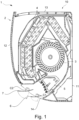
- the wall-mounted indoor unit 10 is entirely elongated in one direction and mounted on a wall surface of a room so that its longitudinal direction is horizontal. As shown in Fig. 1 , the wall-mounted indoor unit 10 includes a casing 2, an indoor fan 3 accommodated in the casing 2, an indoor heat exchanger 4, sideward deflectors 5, a first horizontal deflector 6 (first horizontal flap; sub flap), a second horizontal deflector 7 (second horizontal flap; main flap), and the like.
- the casing 2 includes a substantially box-shaped casing base 11 and a front panel 12.
- the casing base 11 is open at the front, and the front panel 12 covers the open front portion of the casing base 11.
- the casing base 11 includes an upper surface, in which an indoor inlet 13 is formed, and a lower surface, in which an indoor outlet 14 is formed.
- the indoor inlet 13 is a grid-like opening elongated in a sideward direction
- the indoor outlet 14 is a rectangular opening elongated in the sideward direction.
- the indoor fan 3 which is arranged in an airflow path from the indoor inlet 13 to the indoor outlet 14, is driven to draw in air through the indoor inlet 13 so that the air performs heat exchange (i.e., becomes heated or cooled) in the indoor heat exchanger 4 and is then blown out of the indoor outlet 14 into the room.
- heat exchange i.e., becomes heated or cooled
- the sideward deflectors 5 are arranged at an inner side of the indoor outlet 14 to adjust an air direction of the air blown out of the indoor outlet 14 in the sideward direction.
- the first horizontal deflector 6 adjusts the air direction of the air blown out of the indoor outlet 14 in a vertical direction.
- the first horizontal deflector 6 includes a pivot centre C1 at an intermediate position of the indoor outlet 14 in the vertical direction.
- the first horizontal deflector 6 indicated by the solid lines in Fig. 1 is located at the uppermost position in a blow-out direction adjustment range of the first horizontal deflector 6. Further, the first horizontal deflector 6 indicated by the double-dashed lines in Fig. 1 is located at the lowermost position in the blow-out direction adjustment range of the first horizontal deflector 6.
- the uppermost position in the blow-out direction adjustment range corresponds to a position at which the first horizontal deflector 6 is practically horizontal in the same manner as a typical wall-mounted indoor unit.
- the first horizontal deflector 6 is configured to be swung by a drive motor (not shown) between the solid line position and the double-dashed line position and held at any position between the solid line position and the double-dashed line position.
- the second horizontal deflector 7 (main flap) is arranged along an upper structural portion of the indoor outlet 14 to prevent water from collecting on the inner surface of the first horizontal deflector 6 during a cooling operation.
- the second horizontal deflector 7 is configured to adjust the air direction of the blown-out air between a solid line position and a double-dashed line position in Fig. 1 about a pivot center C2.
- the second horizontal deflector 7 is automatically controlled to be held at an optimal position in cooperation with the position of the first horizontal deflector 6 in the blow-out direction adjustment range during a cooling operation. However, during a heating operation, the second horizontal deflector 7 is held at the uppermost position (solid line in Fig. 1 ) in a blow-out direction adjustment range.
- the first horizontal deflector 6 and the second horizontal deflector 7 are each configured to be pivoted to a position located further upward from the uppermost position in the corresponding blow-out direction adjustment range so that the first horizontal deflector 6 and the second horizontal deflector 7 are in contact with the upper structural portion of the indoor outlet 14 (that is, closed positions) to close the indoor outlet 14.
- the first horizontal deflector 6 and the second horizontal deflector 7 also serve as cover members of the indoor outlet 14.
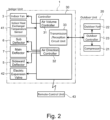
- FIG. 2 shows a functional block diagram of the air conditioner 1 in accordance with one embodiment of the present invention.
- the wall-mounted indoor unit 10 incorporates a controller 30 that entirely controls the operation of the air conditioner.
- the controller 30 is configured by a memory that stores predetermined control programs, a processor that runs on the control programs to perform various controls, and the like.
- the controller 30 includes an air volume controller 31 and an air direction controller 32.
- the air volume controller 31 restricts the air volume produced by the indoor fan 3 at the start of a heating operation.
- the air direction controller 32 controls the vertical air direction with the first horizontal deflector 6 and the second horizontal deflector 7.
- the controller 30 further includes a transmission/reception circuit unit 33, which performs communication with the outdoor unit 20, and the like.
- the controller 30 may comprise one or more processing units or modules (e.g., a central processing unit (CPU) such as a microprocessor, or a suitably programmed field programmable gate array (FPGA) or application-specific integrated circuit (ASIC)). Additionally, or alternatively, the controller 30 may be provided with any memory sections (not shown) necessary to perform its function of controlling operation of the air conditioner 1. Such memory sections may be provided as part of (comprised in) the controller 30 (e.g., integrally formed or provided on the same chip) or provided separately, but electrically connected to the controller 30. By way of example, the memory sections may comprise both volatile and non-volatile memory resources, including, for example, a working memory (e.g., a random access memory).
- a working memory e.g., a random access memory
- the memory sections may include an instruction store (e.g., a ROM in the form of an electrically-erasable programmable read-only memory (EEPROM) or flash memory) storing a computer program comprising computer-readable instructions which, when executed by the controller 30, cause the controller 30 to perform various functions described herein.
- an instruction store e.g., a ROM in the form of an electrically-erasable programmable read-only memory (EEPROM) or flash memory
- EEPROM electrically-erasable programmable read-only memory
- flash memory storing a computer program comprising computer-readable instructions which, when executed by the controller 30, cause the controller 30 to perform various functions described herein.
- the computer program comprising the computer-readable instructions which, when executed by the controller 30, cause the controller 30 to perform various functions described herein may, for example, be a software or a firmware program.
- the control device 30 is connected to the indoor fan 3 and an indoor heat-exchanger temperature sensor 41.
- the indoor fan 3 is an indoor circulation fan that circulates the air, which has undergone heat exchange in the indoor heat exchanger 4, indoors.
- the indoor fan 3 includes a drive motor, of which rotational speed is controlled based on an instruction from the air volume controller 31 for control of the air volume.
- the indoor heat-exchanger temperature sensor 41 is attached to the indoor heat exchanger 4 at a position that allows for detection of an average temperature of the indoor heat exchanger 4 as an indoor heat exchanger temperature Tr.
- the indoor heat exchanger temperature Tr detected by the indoor heat-exchanger temperature sensor 41 is transmitted to the controller 30 and used as reference data for the air volume control of the indoor fan 3 by the air volume controller 31 and the air direction control of the first horizontal deflector 6 and the second horizontal deflector 7 by the air direction controller 32.
- controller 30 is connected to drive units of the first horizontal deflector 6, the second horizontal deflector 7, and the sideward deflector 5 so that the deflectors are controlled by the air direction controller 32.
- control device 30 is connected to an electric expansion valve 42 that controls a refrigerant to the indoor heat exchanger 4. An opening degree of the electric expansion valve 42 is controlled by an instruction from the controller 30.
- the wall-mounted indoor unit 10 includes a remote-control unit 43 as an accessory.
- the remote-control unit 43 functions as an operation unit of the air conditioner 1 and includes an operation switch, an operation mode selection portion, a setting portion, an air volume setting portion, a means of feedback (e.g., a display), and the like.
- the operation switch starts and ends operation of the air conditioner 1.
- the setting portion sets a set temperature for the indoor air.
- the air volume setting portion sets the air volume of the indoor fan during a normal heating operation.
- the display shows the indoor temperature or the air volume of the indoor fan.
- the remote-control unit 43 is configured to transmit operating information, which is selected or set, to the controller 30 through wireless communication.
- the outdoor unit 20 includes a compressor 21, an outdoor fan 22, as well as an outdoor controller 23 that controls these devices. Further, the outdoor unit 20 includes a four-way switching valve (not shown) that switches a refrigerant circuit between a cooling cycle and a heating cycle. The switching of the four-way switching valve is controlled by the outdoor controller 23. Also, the controller 30 of the wall-mounted indoor unit 10 is electrically connected to the outdoor controller 23 via the transmit/receive circuit unit 33, and operating information from the remote-control unit 43 received by the controller 30 is also transmitted to the outdoor controller 23.
- the outdoor unit further comprises an outdoor air temperature sensor (not shown) for monitoring the outdoor air temperature.
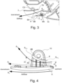
- Figure 3 shows a partial view of the cross-sectional view of the wall-mounted indoor unit 1 of Figure 1 , showing in more detail the first horizontal flap 6 (sub flap) and the second horizontal flap 7 (main flap).
- the first horizontal flap 6 has a first surface 6A and a second surface 6B which are used to guide the blowout air in a desired direction.
- the first surface 6A faces upwards, towards the second horizontal flap 7, in particular towards the lower surface 7A of the second horizontal flap 7.
- an auxiliary flap 8 is provided having a third surface 8A facing the first surface 6A of the first horizontal flap 6.
- the third surface 8A of the auxiliary flap 8 faces downward.
- the auxiliary flap 8 has a shape and orientation, in particular an arcuate shape, such that the auxiliary flap 8 extends from an airflow upstream side to an airflow downstream side of the flap 8 towards the second horizontal flap 7 (main flap), in particular in an open position of the two flaps 6 and 7.
- the auxiliary flap 8 has an arcuate shape, in particular the third surface 8A of the auxiliary flap 8 has a shape that at least partially approximates a first arc, the blowout air flowing along the third surface is deflected towards the lower surface 7A of the second horizontal flap 7 facing the first surface 6A of the first horizontal flap 6.
- Figure 4 shows a schematic cross-sectional side view of a first horizontal flap with an auxiliary flap in accordance with one embodiment of the present invention.
- the first horizontal flap 6 is provided with an auxiliary flap 8, which is provided on the first surface 6A of the first horizontal flap 6.
- the term "provided on the first surface” is to be understood such that the auxiliary flap 8 is provided with the first horizontal flap 6, in particular on a side of the first surface 6A, but not necessarily directly on the first surface 6A.
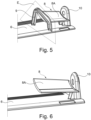
- the auxiliary flap 8 is provided at some distance from the first surface 6A and is supported or fixed by some supporting means, such as the support part 9 shown in Figure 5 .
- the auxiliary flap 8 is only supported by a mounting part 10 of the first auxiliary flap 8, which is used to fix the first auxiliary flap 8 to its rotational drive shaft (not shown).
- Figure 4 also shows that the auxiliary flap 8 has a fourth surface 8B facing the lower surface 7A of the second horizontal flap 7 (shown in Figure 3 ) having a shape that at least partially approximates a second arc, so that the blowout air flowing along the fourth surface 8B is deflected towards the lower surface 7A of the second horizontal flap 7 (main flap).
- the airflow direction is from the right to the left. Without the auxiliary flap 8 being provided on the first horizontal flap 6, the airflow would flow in general along the side surfaces 6A and 6B of the flap 6, as indicated by the arrows A G .
- auxiliary flap 8 on the first horizontal flap 6, the air flowing along the first surface 6A of the flap 6 is deflected upwards, namely towards the second horizontal flap 7 as indicated by the arrow A D .
- auxiliary flap on the airflow upstream side of the horizontal flap 6.
- a first distance D 1 defined between a first end 8End 1 of the airflow downstream side of the auxiliary flap 8 and the first surface 6A, is bigger than a second distance D 2 , defined between a second end 8End 2 of the airflow upstream side of the auxiliary flap 8 and the first surface 6A.
- a third distance D 3 defined between the third surface 8A of the auxiliary flap 8 and the first surface 6A of the first horizontal flap 6, gradually increases from the airflow upstream side towards the airflow downstream side of the auxiliary flap 8.
- the auxiliary flap 8 is supported not only by the mounting part 10, but also by the support part 9.
- the support part 9 is formed integral with the first horizontal flap 6, in particular in a direction perpendicular to the first surface 6A of the first horizontal flap 6.
- the support part 9 may also be formed as a separate part which is fixed to the first horizontal flap 6 by a fixing means such as a screw.
- Figure 6 shows a schematic spatial view of the first horizontal flap with an auxiliary flap in accordance with an alternative embodiment, third embodiment of the present invention, in which the auxiliary flap 8 is not supported by a support part 9. Instead, the auxiliary flap 8 is formed as part of the mounting part 10, extending longitudinally towards the centre of the first horizontal flap 6.
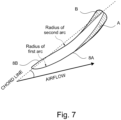
- FIG. 7 shows a schematic cross-sectional view of the auxiliary flap 8 in accordance with the present invention.
- the first arc of the third surface 8A of the auxiliary flap 8 is formed in a plane E (shown in Fig. 5 ) parallel to the blow-out direction of the air (airflow) and perpendicular to a pivot axis X1 about which the first horizontal flap 6 is pivoted (shown in Fig. 3 ), wherein a centre of the first arc lies on the side of the auxiliary flap 8 facing the second horizontal flap 7.
- the third surface 8A of the auxiliary flap 8 is formed convex towards the first surface 6A of the first horizontal flap 6.
- the second arc of the fourth surface 8B of the auxiliary flap 8 is formed in the plane E parallel to the blow-out direction of the air and perpendicular to a/the pivot axis X1 of the first horizontal flap 6, wherein a centre of the second arc lies on the side of the auxiliary flap 8 facing the second horizontal flap 7.
- the fourth surface 8B of the auxiliary flap 8 is formed concave towards the lower surface 7A of the second horizontal flap 7.
- the radius of the first arc is smaller than the radius of the second arc.
- Figure 7 further shows that a thickness of the auxiliary flap 8 on the downstream side of the airflow is greater than its thickness on the upstream side of the airflow.
- the curvature of the fourth surface 8B of the auxiliary flap increases towards its downstream end.
- the auxiliary flap 8 can be provided with a first section A, which lies on the airflow downstream side of the auxiliary flap 8 outside (radially outward) the radius of the first arc. In this way, it is possible to increase the thickness of the auxiliary flap 8 at the airflow downstream side, wherein the thickness of the first section A gradually increases towards the airflow downstream side of the auxiliary flap 8.
- auxiliary flap 8 with a second section B, which lies on the airflow downstream side of the auxiliary flap 8 inside (radially inward) the radius of the second arc. In this way, it is possible to further increase the thickness of the auxiliary flap 8 at the airflow downstream side, wherein preferably the thickness of the second section B gradually increases towards the airflow downstream side of the auxiliary flap 8. In this way, it is additionally possible to increase the curvature of the fourth surface 8B of the auxiliary flap 9 towards its downstream end.
- Figure 8 shows an airflow simulation of conventional horizontal flaps (main flap and sub flap) without the installation of an auxiliary flap.
- the sub flap cannot sufficiently support the main flap. In other words, the sub flap cannot generate sufficient upward airflow to push the air flowing along the main flap upwards, closer to the lower surface 7A of the main flap (second horizontal flap).
- the airflow along the main flap does not fully conform to the shape of the main flap, particularly at the end of the main flap (as seen in the direction of airflow).
- the airflow breaks away from the surface of the main flap, leaving an area of slow flowing air (having low velocity) on the downstream side of the lower surface 7A of the main flap (second horizontal flap).
- the airflow velocity near the lower surface 7A, in particular at its end is low, condensation occurs in the area of low velocity, resulting in the formation of undesired water droplets.
- Figure 9 shows an airflow simulation of an arrangement of horizontal flaps according to the present invention, namely using a sub flap having an auxiliary flap.
- the sub flap first horizontal flap 6
- the auxiliary flap 8 the high velocity air flowing along the first surface (upper surface) 6A of the sub flap 6 is guided upwards towards the lower surface 7A of the main flap (second horizontal flap).
- the air normally flowing along the main flap and breaking away from the surface of the main flap is pushed upwards closer to the surface of the main flap. This avoids an area of slow flowing air (with low velocity) on the downstream side of the lower surface 7A of the main flap (second horizontal flap) .
Landscapes
- Engineering & Computer Science (AREA)
- Chemical & Material Sciences (AREA)
- Combustion & Propulsion (AREA)
- Mechanical Engineering (AREA)
- General Engineering & Computer Science (AREA)
- Air-Flow Control Members (AREA)
Abstract
The present invention relates to an air conditioner 1, in particular an indoor unit, having a fan 3 inside and being configured to blow, from an outlet 14, air sucked by the fan from an inlet 13, the air conditioner includes: a first horizontal flap 6 having a first surface 6A and a second surface 6B that guide the blowout air, which is provided rotatably at the outlet 14, a second horizontal flap 7 placed above the first horizontal flap 6 and on the downstream side of the airflow in an installation situation of the air conditioner 1, and an auxiliary flap 8 provided on the first surface 6A of the first horizontal flap 6, wherein the auxiliary flap 8 has a third surface 8A facing the first surface 6A, the third surface 8A of the auxiliary flap 8 having a shape that at least partially approximates a first arc, so that the blowout air flowing along the third surface 8A is guided towards the lower surface 7A of the second horizontal flap 7 facing the first surface 6A of the first horizontal flap 6.
Description
- The present invention relates to an air conditioner. More particularly, the present invention relates to such air conditioner having an auxiliary flap provided on the sub flap.
- A conventional air conditioner, in particular a wall-mounted indoor unit, in general includes an indoor heat exchanger, an indoor fan that circulates air, which has undergone heat exchange in the indoor heat exchanger, indoors; an indoor outlet that blows out the air, which has undergone heat exchange in the indoor heat exchanger, indoors; a main horizontal deflector (main flap) that is arranged in the indoor outlet to change an air direction in a vertical direction and a sub horizontal deflector (sub flap), and the like.
- As the air that flows around the main horizontal deflector (main flap) has high velocity, based on Bernoulli's equation, there is a pressure drop at the two edges of the main horizontal deflector. Due to the greater pressure drop, ambient moister air is sucked in from the side. This side airflow brings moisture and because of this, more sweat is produced on the edges of the main horizontal deflector. Depending on the angle of the main horizontal deflector, this effect is weaker or stronger. In addition, if for example, the vertical deflectors are turned to the left to direct the airflow to the left, there will be less airflow around the right edge of the horizontal deflectors, particularly the main horizontal deflector, increasing the formation of condensation (sweat). In addition, the fan guard provided to protect fingers from the rotating fan reduces the airflow and therefore increases the risk of condensation forming on the edges (corners) of the main horizontal deflector. Therefore, in order to avoid or reduce the generation/formation of condensation (sweat), it is necessary to reduce the working area (angle) of the main horizontal deflector and the sub horizontal deflector, especially in relation to each other. However, setting the combination of flap angles to match the movement so that generation of condensation (sweat) is avoided or at least reduced, has the disadvantage that the maximum airflow of the air conditioner cannot be achieved, resulting in a decrease in capacity and efficiency.
- In view of the above, there is the desire to provide an air conditioner that is capable of maintaining the maximum airflow of the air conditioner independent of ambient air temperature and humidity, thereby increasing capacity and efficiency, while avoiding generation of sweat at the main flap, in particular on the two opposite edges of the main flap. This aim may be achieved by an air conditioner as defined in
claim 1. Embodiments may be found in the dependent claims, the following description and the accompanying drawings. - In particular, in view of the limitations discussed above, the present inventors have devised, in accordance with a first aspect herein, an air conditioner, in particular an indoor unit, more particularly an indoor unit of a separate type air conditioner, having a fan inside and being configured to blow, from an outlet, air sucked by the fan from an inlet, the air conditioner including: a first horizontal flap (horizontal deflector; sub flap) having a first surface and a second surface that guide the blowout air, which is provided rotatably at the outlet, a second horizontal flap (horizontal deflector; main flap) placed above the first horizontal flap and on the downstream side of the airflow in an installation situation of the air conditioner, and an auxiliary flap provided on the first surface of the first horizontal flap, wherein the auxiliary flap has a third surface facing the first surface of the first horizontal flap, the third surface of the auxiliary flap having a shape that at least partially approximates a first arc, so that the blowout air flowing along the third surface is guided or deflected towards the lower surface of the second horizontal flap facing the first surface of the first horizontal flap.
- Hence, an air conditioner is provided, capable of increasing capacity and efficiency of the air conditioner by maintaining the maximum airflow of the air conditioner, independent of ambient air temperature and humidity, while avoiding or at least reducing generation of sweat at the main flap, in particular on the two opposite edges of the main flap.
- As used herein, the term or feature "at least partially approximates a first arc" refers to any type of shape that in approximation replicates the shape of an arc. Accordingly, the third surface of the auxiliary flap can also be formed by for example three (at least three) straight portions or increments that replicate an arc.
- Furthermore, as used herein, the term "guided" with respect to the auxiliary flap, in particular the third surface, refers to altering or changing the flow direction of the blowout air towards a desired direction or point, in case of the third surface of
auxiliary flap 8 towards the lower surface of the second horizontal flap. - According to a further aspect of the present invention, the first arc of the third surface of the auxiliary flap is formed in a plane parallel to the blow-out direction of the air and perpendicular to a pivot axis X1 about which the first horizontal flap is pivoted, wherein a centre of the first arc preferably lies on the side of the auxiliary flap facing the second horizontal flap. In other words, the third surface of the auxiliary flap is formed convex towards the first surface of the first horizontal flap.
- Furthermore, in some aspects of the present invention, the auxiliary flap has a fourth surface facing the lower surface of the second horizontal flap having a shape that at least partially approximates a second arc, so that the blowout air flowing along the fourth surface is guided or deflected towards the lower surface of the second horizontal flap.
- Moreover, in some aspects of the present invention, the second arc of the fourth surface of the auxiliary flap is formed in a/the plane parallel to the blow-out direction of the air and perpendicular to a/the pivot axis X1 about which the first horizontal flap is pivoted, wherein a centre of the second arc preferably lies on the side of the auxiliary flap facing the second horizontal flap. In other words, the fourth surface of the auxiliary flap is formed concave towards the lower surface of the second horizontal flap.
- In some aspects, the radius of the first arc is smaller than the radius of the second arc.
- According to a further aspect of the present invention, the auxiliary flap is placed on the airflow upstream side of the first surface of the horizontal flap.
- Moreover, in some aspects the auxiliary flap when viewed in a cross-section parallel to the blow-out direction of the air and perpendicular to a/the pivot axis X1 about which the first horizontal flap is pivoted, thickness of the auxiliary flap on the downstream side of the airflow is bigger than the thickness of it on the upstream side of the airflow.
- In some aspects of the present invention, a first distance D1 between a first end of the airflow downstream side of the auxiliary flap and the first surface is bigger than a second distance D2 between a second end of the airflow upstream side of the auxiliary flap and the first surface.
- According to a further aspect of the air conditioner of the present invention, a third distance D3 between the third surface of the auxiliary flap and the first surface of the first horizontal flap gradually increases from the airflow upstream side towards the airflow downstream side of the auxiliary flap. In other words, although the third surface of the auxiliary flap is formed convex towards the first surface of the first horizontal flap, the auxiliary flap is arranged and orientated in such way that the closest point of the auxiliary flap to the first horizontal flap lies on the most airflow upstream point of the auxiliary flap. Accordingly, the third distance D3 increases from the value of the second distance D2 to the value of the first distance D1.
- Moreover, in some aspects the first horizontal flap has a support part that is preferably formed integral with the first horizontal flap and supports the auxiliary flap, in particular in a direction perpendicular to the first surface of the first horizontal flap.
- According to a further aspect of the present invention, the auxiliary flap, when viewed in a cross-section parallel to the blow-out direction of the air and perpendicular to a/the pivot axis X1 about which the first horizontal flap is pivoted, includes a first section, which is arranged on the airflow downstream side of the auxiliary flap outside the radius of the first arc, thereby increasing the thickness of the auxiliary flap at the airflow downstream side, wherein preferably the thickness of the first section gradually increases towards the airflow downstream side of the auxiliary flap. In this way it is possible to improve the Coanda effect of the auxiliary flap. By improving the Coanda effect, the formation/generation of condensation (sweat) on the lower surface of the second horizontal flap (main flap) and the third surface (lower surface) of the auxiliary flap can be reduced.
- In some aspects of the present invention, the auxiliary flap, when viewed in a cross-section parallel to the blow-out direction of the air and perpendicular to a/the pivot axis X1 about which the first horizontal flap is pivoted, includes a second section, which is arranged on the airflow downstream side of the auxiliary flap inside the radius of the second arc, thereby increasing the thickness of the auxiliary flap at the airflow downstream side, wherein preferably the thickness of the second section gradually increases towards the airflow downstream side of the auxiliary flap. In this way it is possible to build a countermeasure for the main flap (second horizontal flap). In other words, by adding the second section to the auxiliary flap, the angle/curvature of the auxiliary flap can be increased on the downstream side of the airflow towards the second horizontal flap (main flap), thus providing more flexibility with respect to the working angle range of the main and sub flaps. More specifically, by adding the second section to the auxiliary flap, the deflection of the airflow at the sub flap can be increased, making it unnecessary to change the angle of the sub flap too much upwards, thereby ensuring maximum airflow.
- Furthermore, in some aspects, two auxiliary flaps are provided on the first surface of the first horizontal flap on opposite sides of the first horizontal flap, in a direction parallel to the pivot axis X1, both auxiliary flaps extending a predetermined length from the respective end of the first horizontal flap towards each other.
- According to a further aspect of the present invention, the first arc and/or the second arc are formed such way that the blowout air flowing along the auxiliary flap is guided or deflected towards a predetermined area on the airflow downstream side of the lower surface of the second horizontal flap.
- A more complete appreciation of the present invention and many of the attendant advantages thereof will be readily obtained as the same becomes better understood by reference to the following detailed description when considered in connection with the accompanying drawings, in which:
- Fig. 1
- shows a schematic cross-sectional view of a wall-mounted indoor unit of an air conditioner in accordance with one embodiment of the present invention;
- Fig. 2
- shows a functional block diagram of the air conditioner in accordance with one embodiment of the present invention;
- Fig. 3
- shows a partial view of the cross-sectional view of the wall-mounted indoor unit of
Fig. 1 , - Fig. 4
- shows a schematic cross-sectional side view of a first horizontal flap with an auxiliary flap in accordance with one embodiment of the present invention,
- Fig. 5
- shows a schematic spatial view of the first horizontal flap with an auxiliary flap in accordance with a second embodiment of the present invention,
- Fig. 6
- shows a schematic spatial view of the first horizontal flap with an auxiliary flap in accordance with a third embodiment of the present invention,
- Fig. 7
- shows a schematic cross-sectional view of the auxiliary flap in accordance with the present invention,
- Fig. 8
- shows an airflow simulation of a conventional arrangement of horizontal flaps without an auxiliary flap, and
- Fig. 9
- shows an airflow simulation of an arrangement of horizontal flaps according to the present invention using a sub flap having an auxiliary flap.
- Embodiments of the present disclosure will now be explained with reference to the drawings. It will be apparent to those skilled in the field of air conditioning devices from this disclosure that the following description of the embodiments is provided for illustration only and not for the purpose of limiting the disclosure as defined by the appended claims. Features of the embodiments described below can also be used to further characterize the devices and method defined in the claims.
- Modifications of features can be combined to form further embodiments. Features described in individual embodiments can be provided in a single embodiment if they are not incompatible. Likewise, features described in a single embodiment can be provided in several embodiments individually or in any suitable sub-combination. As used in the specification and the appended claims, the singular forms "a", "an", "the" and the like include plural referents unless the context clearly dictates otherwise.
- The same reference numerals listed in different drawings refer to identical, corresponding or functionally similar elements. Moreover, where technical features in the drawings, detailed description or any claims are followed by reference signs, the reference signs have been included for the sole purpose of increasing the intelligibility of the drawings, detailed description, and claims. Accordingly, neither the reference signs nor their absence has any limiting effect on the scope of any claim elements.
- As described hereinafter, example implementations of the present invention relate to an air conditioner.
- The air conditioner in accordance with the present embodiment includes a wall-mounted
indoor unit 1 shown inFigure 1 and an outdoor unit 20 (refer toFigure 2 ) and performs heat-pump type cooling and heating operations. - The wall-mounted
indoor unit 10 is entirely elongated in one direction and mounted on a wall surface of a room so that its longitudinal direction is horizontal. As shown inFig. 1 , the wall-mountedindoor unit 10 includes acasing 2, anindoor fan 3 accommodated in thecasing 2, anindoor heat exchanger 4,sideward deflectors 5, a first horizontal deflector 6 (first horizontal flap; sub flap), a second horizontal deflector 7 (second horizontal flap; main flap), and the like. - The
casing 2 includes a substantially box-shapedcasing base 11 and afront panel 12. Thecasing base 11 is open at the front, and thefront panel 12 covers the open front portion of thecasing base 11. Thecasing base 11 includes an upper surface, in which anindoor inlet 13 is formed, and a lower surface, in which anindoor outlet 14 is formed. Theindoor inlet 13 is a grid-like opening elongated in a sideward direction, and theindoor outlet 14 is a rectangular opening elongated in the sideward direction. When performing an air conditioning operation (cooling operation or heating operation), theindoor fan 3, which is arranged in an airflow path from theindoor inlet 13 to theindoor outlet 14, is driven to draw in air through theindoor inlet 13 so that the air performs heat exchange (i.e., becomes heated or cooled) in theindoor heat exchanger 4 and is then blown out of theindoor outlet 14 into the room. - The
sideward deflectors 5 are arranged at an inner side of theindoor outlet 14 to adjust an air direction of the air blown out of theindoor outlet 14 in the sideward direction. - The first
horizontal deflector 6 adjusts the air direction of the air blown out of theindoor outlet 14 in a vertical direction. The firsthorizontal deflector 6 includes a pivot centre C1 at an intermediate position of theindoor outlet 14 in the vertical direction. The firsthorizontal deflector 6 indicated by the solid lines inFig. 1 is located at the uppermost position in a blow-out direction adjustment range of the firsthorizontal deflector 6. Further, the firsthorizontal deflector 6 indicated by the double-dashed lines inFig. 1 is located at the lowermost position in the blow-out direction adjustment range of the firsthorizontal deflector 6. The uppermost position in the blow-out direction adjustment range corresponds to a position at which the firsthorizontal deflector 6 is practically horizontal in the same manner as a typical wall-mounted indoor unit. Further, in response to an operation instruction of a user during a cooling operation or a heating operation, the firsthorizontal deflector 6 is configured to be swung by a drive motor (not shown) between the solid line position and the double-dashed line position and held at any position between the solid line position and the double-dashed line position. - The second horizontal deflector 7 (main flap) is arranged along an upper structural portion of the
indoor outlet 14 to prevent water from collecting on the inner surface of the firsthorizontal deflector 6 during a cooling operation. The secondhorizontal deflector 7 is configured to adjust the air direction of the blown-out air between a solid line position and a double-dashed line position inFig. 1 about a pivot center C2. The secondhorizontal deflector 7 is automatically controlled to be held at an optimal position in cooperation with the position of the firsthorizontal deflector 6 in the blow-out direction adjustment range during a cooling operation. However, during a heating operation, the secondhorizontal deflector 7 is held at the uppermost position (solid line inFig. 1 ) in a blow-out direction adjustment range. - Further, when a cooling operation and a heating operation are stopped, the first
horizontal deflector 6 and the secondhorizontal deflector 7 are each configured to be pivoted to a position located further upward from the uppermost position in the corresponding blow-out direction adjustment range so that the firsthorizontal deflector 6 and the secondhorizontal deflector 7 are in contact with the upper structural portion of the indoor outlet 14 (that is, closed positions) to close theindoor outlet 14. In this manner, the firsthorizontal deflector 6 and the secondhorizontal deflector 7 also serve as cover members of theindoor outlet 14. -
Figure 2 shows a functional block diagram of theair conditioner 1 in accordance with one embodiment of the present invention. As shown inFigure 2 , the wall-mountedindoor unit 10 incorporates acontroller 30 that entirely controls the operation of the air conditioner. Thecontroller 30 is configured by a memory that stores predetermined control programs, a processor that runs on the control programs to perform various controls, and the like. Further, thecontroller 30 includes anair volume controller 31 and anair direction controller 32. Theair volume controller 31 restricts the air volume produced by theindoor fan 3 at the start of a heating operation. Theair direction controller 32 controls the vertical air direction with the firsthorizontal deflector 6 and the secondhorizontal deflector 7. Thecontroller 30 further includes a transmission/reception circuit unit 33, which performs communication with theoutdoor unit 20, and the like. - The
controller 30 may comprise one or more processing units or modules (e.g., a central processing unit (CPU) such as a microprocessor, or a suitably programmed field programmable gate array (FPGA) or application-specific integrated circuit (ASIC)). Additionally, or alternatively, thecontroller 30 may be provided with any memory sections (not shown) necessary to perform its function of controlling operation of theair conditioner 1. Such memory sections may be provided as part of (comprised in) the controller 30 (e.g., integrally formed or provided on the same chip) or provided separately, but electrically connected to thecontroller 30. By way of example, the memory sections may comprise both volatile and non-volatile memory resources, including, for example, a working memory (e.g., a random access memory). In addition, the memory sections may include an instruction store (e.g., a ROM in the form of an electrically-erasable programmable read-only memory (EEPROM) or flash memory) storing a computer program comprising computer-readable instructions which, when executed by thecontroller 30, cause thecontroller 30 to perform various functions described herein. - The computer program comprising the computer-readable instructions which, when executed by the
controller 30, cause thecontroller 30 to perform various functions described herein may, for example, be a software or a firmware program. - The
control device 30 is connected to theindoor fan 3 and an indoor heat-exchanger temperature sensor 41. Theindoor fan 3 is an indoor circulation fan that circulates the air, which has undergone heat exchange in theindoor heat exchanger 4, indoors. Theindoor fan 3 includes a drive motor, of which rotational speed is controlled based on an instruction from theair volume controller 31 for control of the air volume. - The indoor heat-
exchanger temperature sensor 41 is attached to theindoor heat exchanger 4 at a position that allows for detection of an average temperature of theindoor heat exchanger 4 as an indoor heat exchanger temperature Tr. The indoor heat exchanger temperature Tr detected by the indoor heat-exchanger temperature sensor 41 is transmitted to thecontroller 30 and used as reference data for the air volume control of theindoor fan 3 by theair volume controller 31 and the air direction control of the firsthorizontal deflector 6 and the secondhorizontal deflector 7 by theair direction controller 32. - Further, the
controller 30 is connected to drive units of the firsthorizontal deflector 6, the secondhorizontal deflector 7, and thesideward deflector 5 so that the deflectors are controlled by theair direction controller 32. In addition, thecontrol device 30 is connected to anelectric expansion valve 42 that controls a refrigerant to theindoor heat exchanger 4. An opening degree of theelectric expansion valve 42 is controlled by an instruction from thecontroller 30. - Also, the wall-mounted
indoor unit 10 includes a remote-control unit 43 as an accessory. The remote-control unit 43 functions as an operation unit of theair conditioner 1 and includes an operation switch, an operation mode selection portion, a setting portion, an air volume setting portion, a means of feedback (e.g., a display), and the like. The operation switch starts and ends operation of theair conditioner 1. The setting portion sets a set temperature for the indoor air. The air volume setting portion sets the air volume of the indoor fan during a normal heating operation. The display shows the indoor temperature or the air volume of the indoor fan. The remote-control unit 43 is configured to transmit operating information, which is selected or set, to thecontroller 30 through wireless communication. - The
outdoor unit 20 includes acompressor 21, anoutdoor fan 22, as well as anoutdoor controller 23 that controls these devices. Further, theoutdoor unit 20 includes a four-way switching valve (not shown) that switches a refrigerant circuit between a cooling cycle and a heating cycle. The switching of the four-way switching valve is controlled by theoutdoor controller 23. Also, thecontroller 30 of the wall-mountedindoor unit 10 is electrically connected to theoutdoor controller 23 via the transmit/receivecircuit unit 33, and operating information from the remote-control unit 43 received by thecontroller 30 is also transmitted to theoutdoor controller 23. The outdoor unit further comprises an outdoor air temperature sensor (not shown) for monitoring the outdoor air temperature. -
Figure 3 shows a partial view of the cross-sectional view of the wall-mountedindoor unit 1 ofFigure 1 , showing in more detail the first horizontal flap 6 (sub flap) and the second horizontal flap 7 (main flap). As can be seen fromFigure 3 , the firsthorizontal flap 6 has afirst surface 6A and asecond surface 6B which are used to guide the blowout air in a desired direction. Thefirst surface 6A faces upwards, towards the secondhorizontal flap 7, in particular towards thelower surface 7A of the secondhorizontal flap 7. On thefirst surface 6A of the firsthorizontal flap 6, anauxiliary flap 8 is provided having athird surface 8A facing thefirst surface 6A of the firsthorizontal flap 6. In other words, inFigure 3 , thethird surface 8A of theauxiliary flap 8 faces downward. As can also be seen inFigure 3 , theauxiliary flap 8 has a shape and orientation, in particular an arcuate shape, such that theauxiliary flap 8 extends from an airflow upstream side to an airflow downstream side of theflap 8 towards the second horizontal flap 7 (main flap), in particular in an open position of the twoflaps auxiliary flap 8 has an arcuate shape, in particular thethird surface 8A of theauxiliary flap 8 has a shape that at least partially approximates a first arc, the blowout air flowing along the third surface is deflected towards thelower surface 7A of the secondhorizontal flap 7 facing thefirst surface 6A of the firsthorizontal flap 6. -
Figure 4 shows a schematic cross-sectional side view of a first horizontal flap with an auxiliary flap in accordance with one embodiment of the present invention. As described above with respect toFigure 3 , the firsthorizontal flap 6 is provided with anauxiliary flap 8, which is provided on thefirst surface 6A of the firsthorizontal flap 6. AsFigure 4 shows, in the context of the present invention, the term "provided on the first surface" is to be understood such that theauxiliary flap 8 is provided with the firsthorizontal flap 6, in particular on a side of thefirst surface 6A, but not necessarily directly on thefirst surface 6A. In other words, as is particularly apparent fromFigures 5 and 6 , theauxiliary flap 8 is provided at some distance from thefirst surface 6A and is supported or fixed by some supporting means, such as thesupport part 9 shown inFigure 5 . In the embodiment shown inFigures 4 and6 , theauxiliary flap 8 is only supported by a mountingpart 10 of the firstauxiliary flap 8, which is used to fix the firstauxiliary flap 8 to its rotational drive shaft (not shown). -
Figure 4 also shows that theauxiliary flap 8 has afourth surface 8B facing thelower surface 7A of the second horizontal flap 7 (shown inFigure 3 ) having a shape that at least partially approximates a second arc, so that the blowout air flowing along thefourth surface 8B is deflected towards thelower surface 7A of the second horizontal flap 7 (main flap). In theFigure 4 the airflow direction is from the right to the left. Without theauxiliary flap 8 being provided on the firsthorizontal flap 6, the airflow would flow in general along the side surfaces 6A and 6B of theflap 6, as indicated by the arrows AG. However, by providing theauxiliary flap 8 on the firsthorizontal flap 6, the air flowing along thefirst surface 6A of theflap 6 is deflected upwards, namely towards the secondhorizontal flap 7 as indicated by the arrow AD. AsFigure 4 also shows, it is preferable to provide the auxiliary flap on the airflow upstream side of thehorizontal flap 6. In addition, as shown inFigure 4 , a first distance D1, defined between a first end 8End1 of the airflow downstream side of theauxiliary flap 8 and thefirst surface 6A, is bigger than a second distance D2, defined between a second end 8End2 of the airflow upstream side of theauxiliary flap 8 and thefirst surface 6A. - More preferably, as shown in
Figure 4 , a third distance D3, defined between thethird surface 8A of theauxiliary flap 8 and thefirst surface 6A of the firsthorizontal flap 6, gradually increases from the airflow upstream side towards the airflow downstream side of theauxiliary flap 8. - As briefly described above, in the embodiment shown in
Figure 5 , which shows a schematic spatial view of the first horizontal flap with an auxiliary flap, theauxiliary flap 8 is supported not only by the mountingpart 10, but also by thesupport part 9. In the present embodiment, thesupport part 9 is formed integral with the firsthorizontal flap 6, in particular in a direction perpendicular to thefirst surface 6A of the firsthorizontal flap 6. However, thesupport part 9 may also be formed as a separate part which is fixed to the firsthorizontal flap 6 by a fixing means such as a screw. -
Figure 6 shows a schematic spatial view of the first horizontal flap with an auxiliary flap in accordance with an alternative embodiment, third embodiment of the present invention, in which theauxiliary flap 8 is not supported by asupport part 9. Instead, theauxiliary flap 8 is formed as part of the mountingpart 10, extending longitudinally towards the centre of the firsthorizontal flap 6. -
Figure 7 shows a schematic cross-sectional view of theauxiliary flap 8 in accordance with the present invention. As can be seen inFigure 7 , the first arc of thethird surface 8A of theauxiliary flap 8 is formed in a plane E (shown inFig. 5 ) parallel to the blow-out direction of the air (airflow) and perpendicular to a pivot axis X1 about which the firsthorizontal flap 6 is pivoted (shown inFig. 3 ), wherein a centre of the first arc lies on the side of theauxiliary flap 8 facing the secondhorizontal flap 7. In other words, thethird surface 8A of theauxiliary flap 8 is formed convex towards thefirst surface 6A of the firsthorizontal flap 6. - As
Figure 7 also shows, the second arc of thefourth surface 8B of theauxiliary flap 8 is formed in the plane E parallel to the blow-out direction of the air and perpendicular to a/the pivot axis X1 of the firsthorizontal flap 6, wherein a centre of the second arc lies on the side of theauxiliary flap 8 facing the secondhorizontal flap 7. In other words, thefourth surface 8B of theauxiliary flap 8 is formed concave towards thelower surface 7A of the secondhorizontal flap 7. As can also be seen inFigure 7 , the radius of the first arc is smaller than the radius of the second arc. -
Figure 7 further shows that a thickness of theauxiliary flap 8 on the downstream side of the airflow is greater than its thickness on the upstream side of the airflow. In other words, the curvature of thefourth surface 8B of the auxiliary flap increases towards its downstream end. In addition, as shown inFigure 7 , theauxiliary flap 8 can be provided with a first section A, which lies on the airflow downstream side of theauxiliary flap 8 outside (radially outward) the radius of the first arc. In this way, it is possible to increase the thickness of theauxiliary flap 8 at the airflow downstream side, wherein the thickness of the first section A gradually increases towards the airflow downstream side of theauxiliary flap 8. - In addition, as also shown in
Figure 7 , it is possible to provide theauxiliary flap 8 with a second section B, which lies on the airflow downstream side of theauxiliary flap 8 inside (radially inward) the radius of the second arc. In this way, it is possible to further increase the thickness of theauxiliary flap 8 at the airflow downstream side, wherein preferably the thickness of the second section B gradually increases towards the airflow downstream side of theauxiliary flap 8. In this way, it is additionally possible to increase the curvature of thefourth surface 8B of theauxiliary flap 9 towards its downstream end. - In the following, the advantages and effects achieved by the air conditioner according to the present invention in comparison with conventional air conditioners will be further explained referring to
Figures 8 and 9. Figure 8 shows an airflow simulation of conventional horizontal flaps (main flap and sub flap) without the installation of an auxiliary flap. As can be seen inFigure 8 , since the opening angle between the main flap (second horizontal flap) and the sub flap (first horizontal flap) must have a certain size to allow the maximum airflow of the air conditioner in order to maintain the capacity and efficiency of the air conditioner, the sub flap cannot sufficiently support the main flap. In other words, the sub flap cannot generate sufficient upward airflow to push the air flowing along the main flap upwards, closer to thelower surface 7A of the main flap (second horizontal flap). Consequently, as shown inFigure 9 , the airflow along the main flap does not fully conform to the shape of the main flap, particularly at the end of the main flap (as seen in the direction of airflow). The airflow breaks away from the surface of the main flap, leaving an area of slow flowing air (having low velocity) on the downstream side of thelower surface 7A of the main flap (second horizontal flap). As the airflow velocity near thelower surface 7A, in particular at its end, is low, condensation occurs in the area of low velocity, resulting in the formation of undesired water droplets. -
Figure 9 shows an airflow simulation of an arrangement of horizontal flaps according to the present invention, namely using a sub flap having an auxiliary flap. As can be seen inFigure 9 , since the sub flap (first horizontal flap 6) is provided with anauxiliary flap 8, the high velocity air flowing along the first surface (upper surface) 6A of thesub flap 6 is guided upwards towards thelower surface 7A of the main flap (second horizontal flap). As part of the airflow of the sub flap is guided upwards towards the main flap, the air normally flowing along the main flap and breaking away from the surface of the main flap is pushed upwards closer to the surface of the main flap. This avoids an area of slow flowing air (with low velocity) on the downstream side of thelower surface 7A of the main flap (second horizontal flap) . Since the air flows closer to thelower surface 7A of the main flap, i.e. the airflow along the main flap conforms to the shape (follows the shape) of the main flap, condensation on thelower surface 7A of the main flap, in particular on its downstream side can be avoided. Thus, the formation of water droplets can be suppressed. In addition, since the velocity of the air flowing along thelower surface 7A of the main flap can be increased, the lateral "humid" air behind the main flap (as seen in the direction of airflow), can be prevented from contacting the main flap, thereby suppressing condensation. The combination of these two effects results in a maximum suppression of condensation on the main flap. - From the above description, the person skilled in the art will recognize that various modifications and variations of the apparatus of the invention can be made without departing from the scope of the invention. Moreover, the invention has been described in relation to particular embodiments, which however are intended solely for better understanding the invention defined by the independent claims, not for limiting the invention. The person skilled in the art will also immediately recognize that many different combinations of elements can be used to carry out the present invention.
- Even if the above-described embodiments state a particular number of components, a different number of these components can be used according to further embodiments.
-
- 1
- Air conditioner
- 2
- Casing
- 3
- Indoor fan
- 4
- Indoor heat exchanger
- 5
- Sideward Deflector
- 6
- First Horizontal Deflector (sub flap)
- 7
- Second Horizontal Deflector (main flap)
- 8
- Auxiliary flap
- 9
- Support part (Auxiliary flap)
- 10
- Indoor unit
- 11
- Casing base
- 12
- Front panel
- 13
- Indoor inlet (Air)
- 14
- Indoor outlet (Air)
- C1
- Pivot center C1
- C2
- Pivot center C2
- 20
- Outdoor unit
- 21
- Compressor
- 22
- Outdoor fan
- 23
- Outdoor controller
- 30
- Controller (Indoor controller)
- 31
- Air volume controller
- 32
- Air direction controller
- 33
- Transmission/Reception circuit unit
- 34
- Remote-Control unit
Claims (14)
- An air conditioner (1), in particular an indoor unit, having a fan (3) inside and being configured to blow, from an outlet (14), air sucked by the fan from an inlet (13), the air conditioner comprising:a first horizontal flap (6) having a first surface (6A) and a second surface (6B) that guide the blowout air, which is provided rotatably at the outlet (14),a second horizontal flap (7) placed above the first horizontal flap (6) and on the downstream side of the airflow in an installation situation of the air conditioner, andan auxiliary flap (8) provided on the first surface (6A) of the first horizontal flap (6),wherein the auxiliary flap (8) has a third surface (8A) facing the first surface (6A), the third surface (8A) of the auxiliary flap (8) having a shape that at least partially approximates a first arc, so that the blowout air flowing along the third surface (8A) is guided towards the lower surface (7A) of the second horizontal flap (7).
- The air conditioner (1) according to claim 1,wherein the first arc of the third surface (8A) of the auxiliary flap (8) is formed in a plane (E) parallel to the blow-out direction of the air and perpendicular to a pivot axis X1 about which the first horizontal flap (6) is pivoted,wherein a centre of the first arc preferably lies on the side of the auxiliary flap (8) facing the second horizontal flap (7).
- The air conditioner (1) according to claim 1 or 2,
wherein the auxiliary flap (8) has a fourth surface (8B) facing the lower surface (7A) of the second horizontal flap (7) having a shape that at least partially approximates a second arc, so that the blowout air flowing along the fourth surface (8B) is guided towards the lower surface (7A) of the second horizontal flap (7). - The air conditioner (1) according to claim 3, wherein the second arc of the fourth surface (8B) of the auxiliary flap (8) is formed in a/the plane (E) parallel to the blow-out direction of the air and perpendicular to a/the pivot axis X1 about which the first horizontal flap (6) is pivoted,
wherein a centre of the second arc preferably lies on the side of the auxiliary flap (8) facing the second horizontal flap (7). - The air conditioner (1) according to claim 3 or 4, wherein the radius of the first arc is smaller than the radius of the second arc.
- The air conditioner (1) according to any one of the preceding claims, wherein the auxiliary flap (8) is placed on the airflow upstream side of the first surface (6A) of the horizontal flap (6).
- The air conditioner (1) according to any one of the preceding claims, wherein the auxiliary flap (8) when viewed in a cross-section parallel to the blow-out direction of the air and perpendicular to a/the pivot axis X1 about which the first horizontal flap (6) is pivoted, thickness of the auxiliary flap (8) on the downstream side of the airflow is bigger than the thickness of it on the upstream side of the airflow.
- The air conditioner (1) according to any one of the preceding claims, wherein a first distance (D1) between a first end (8End1) of the airflow downstream side of the auxiliary flap (8) and the first surface (6A) is bigger than a second distance (D2) between a second end (8End2) of the airflow upstream side of the auxiliary flap (8) and the first surface (6A).
- The air conditioner (1) according to any one of the preceding claims, wherein a third distance (D3) between the third surface (8A) of the auxiliary flap (8) and the first surface (6A) of the first horizontal flap (6) gradually increases from the airflow upstream side towards the airflow downstream side of the auxiliary flap (8).
- The air conditioner (1) according to any one of the preceding claims, wherein the first horizontal flap (6) has a support part (9) that is preferably formed integral with the first horizontal flap (6) and supports the auxiliary flap (8), in particular in a direction perpendicular to the first surface (6A) of the first horizontal flap (6).
- The air conditioner (1) according to any one of the preceding claims, wherein the auxiliary flap (8) when viewed in a cross-section parallel to the blow-out direction of the air and perpendicular to a/the pivot axis X1 about which the first horizontal flap (6) is pivoted comprises a first section (A), which is arranged on the airflow downstream side of the auxiliary flap (8) outside the radius of the first arc, thereby increasing the thickness of the auxiliary flap (8) at the airflow downstream side, wherein preferably the thickness of the first section (A) gradually increases towards the airflow downstream side of the auxiliary flap (8).
- The air conditioner (1) according to any one of claims 4 to 11 and claim 3, wherein the auxiliary flap (8) when viewed in a cross-section parallel to the blow-out direction of the air and perpendicular to a/the pivot axis X1 about which the first horizontal flap (6) is pivoted comprises a second section (B), which is arranged on the airflow downstream side of the auxiliary flap (8) inside the radius of the second arc, thereby increasing the thickness of the auxiliary flap (8) at the airflow downstream side, wherein preferably the thickness of the second section (B) gradually increases towards the airflow downstream side of the auxiliary flap (8).
- The air conditioner (1) according to any one of the preceding claims, wherein two auxiliary flaps (8) are provided on the first surface (8A) of the first horizontal flap (6) on opposite sides of the first horizontal flap (8) to the pivot axis X1], both auxiliary flaps (8) extending a predetermined length from the respective end of the first horizontal flap (6) towards each other.
- The air conditioner (1) according to any one of the preceding claims, wherein the first arc and/or the second arc are formed such way that the blowout air flowing along the auxiliary flap (8) is guided towards a predetermined area (P) on the airflow downstream side of the lower surface (7A) of the second horizontal flap (7).
Priority Applications (3)
| Application Number | Priority Date | Filing Date | Title |
|---|---|---|---|
| EP23191895.4A EP4509765A1 (en) | 2023-08-17 | 2023-08-17 | Air conditioner having an auxiliary flap provided on the sub flap |
| PCT/EP2024/072923 WO2025036940A1 (en) | 2023-08-17 | 2024-08-14 | Air conditioner having an auxiliary flap provided on the sub flap |
| CN202480052552.9A CN121729596A (en) | 2023-08-17 | 2024-08-14 | Air conditioner with auxiliary air deflector arranged on auxiliary air deflector |
Applications Claiming Priority (1)
| Application Number | Priority Date | Filing Date | Title |
|---|---|---|---|
| EP23191895.4A EP4509765A1 (en) | 2023-08-17 | 2023-08-17 | Air conditioner having an auxiliary flap provided on the sub flap |
Publications (1)
| Publication Number | Publication Date |
|---|---|
| EP4509765A1 true EP4509765A1 (en) | 2025-02-19 |
Family
ID=87696028
Family Applications (1)
| Application Number | Title | Priority Date | Filing Date |
|---|---|---|---|
| EP23191895.4A Pending EP4509765A1 (en) | 2023-08-17 | 2023-08-17 | Air conditioner having an auxiliary flap provided on the sub flap |
Country Status (3)
| Country | Link |
|---|---|
| EP (1) | EP4509765A1 (en) |
| CN (1) | CN121729596A (en) |
| WO (1) | WO2025036940A1 (en) |
Citations (4)
| Publication number | Priority date | Publication date | Assignee | Title |
|---|---|---|---|---|
| CN108105859B (en) * | 2017-12-11 | 2020-05-22 | 芜湖美智空调设备有限公司 | Air conditioner indoor unit and control method thereof |
| CN111351130A (en) * | 2020-03-26 | 2020-06-30 | 青岛海尔空调器有限总公司 | Air conditioner indoor unit |
| WO2022068952A1 (en) * | 2021-04-02 | 2022-04-07 | 青岛海尔空调器有限总公司 | Air guide device of air conditioner, and air conditioner |
| EP3982052A1 (en) * | 2020-10-09 | 2022-04-13 | Panasonic Intellectual Property Management Co., Ltd. | Air conditioner |
-
2023
- 2023-08-17 EP EP23191895.4A patent/EP4509765A1/en active Pending
-
2024
- 2024-08-14 WO PCT/EP2024/072923 patent/WO2025036940A1/en not_active Ceased
- 2024-08-14 CN CN202480052552.9A patent/CN121729596A/en active Pending
Patent Citations (4)
| Publication number | Priority date | Publication date | Assignee | Title |
|---|---|---|---|---|
| CN108105859B (en) * | 2017-12-11 | 2020-05-22 | 芜湖美智空调设备有限公司 | Air conditioner indoor unit and control method thereof |
| CN111351130A (en) * | 2020-03-26 | 2020-06-30 | 青岛海尔空调器有限总公司 | Air conditioner indoor unit |
| EP3982052A1 (en) * | 2020-10-09 | 2022-04-13 | Panasonic Intellectual Property Management Co., Ltd. | Air conditioner |
| WO2022068952A1 (en) * | 2021-04-02 | 2022-04-07 | 青岛海尔空调器有限总公司 | Air guide device of air conditioner, and air conditioner |
Also Published As
| Publication number | Publication date |
|---|---|
| WO2025036940A1 (en) | 2025-02-20 |
| CN121729596A (en) | 2026-03-24 |
Similar Documents
| Publication | Publication Date | Title |
|---|---|---|
| JP5611694B2 (en) | Air conditioner | |
| CN111919064A (en) | Indoor unit of air conditioner | |
| CN102472520A (en) | Air flow direction changing device for air adjusting device | |
| US11493231B2 (en) | Indoor unit for air conditioner | |
| JP4749352B2 (en) | Air conditioner | |
| JP6776531B2 (en) | Indoor unit of air conditioner | |
| JP6668552B2 (en) | Air conditioner indoor unit | |
| KR102336631B1 (en) | Air-conditioner | |
| US20220186976A1 (en) | Indoor unit of air conditioner | |
| JPH109659A (en) | Air conditioner | |
| EP3412983B1 (en) | Indoor unit for air conditioners | |
| WO2025036940A1 (en) | Air conditioner having an auxiliary flap provided on the sub flap | |
| JP7436842B2 (en) | floor-standing air conditioner | |
| JP4090315B2 (en) | Air conditioner | |
| EP4202314B1 (en) | Floor-standing air conditioner | |
| CN111902679A (en) | Indoor unit of air conditioner | |
| JPH0599445A (en) | Air conditioner | |
| US12422149B2 (en) | Air conditioner | |
| JP7244773B2 (en) | Wall-mounted air conditioning indoor units and air conditioners | |
| JP4183321B2 (en) | Air conditioner | |
| JP2004316969A (en) | Air conditioner | |
| CN114811723A (en) | Air conditioner indoor unit and air conditioner | |
| JP6344375B2 (en) | Indoor unit of air conditioner | |
| WO2021085459A1 (en) | Indoor unit for air conditioner | |
| JP2019173995A (en) | Air conditioning device |
Legal Events
| Date | Code | Title | Description |
|---|---|---|---|
| PUAI | Public reference made under article 153(3) epc to a published international application that has entered the european phase |
Free format text: ORIGINAL CODE: 0009012 |
|
| STAA | Information on the status of an ep patent application or granted ep patent |
Free format text: STATUS: REQUEST FOR EXAMINATION WAS MADE |
|
| 17P | Request for examination filed |
Effective date: 20240621 |
|
| AK | Designated contracting states |
Kind code of ref document: A1 Designated state(s): AL AT BE BG CH CY CZ DE DK EE ES FI FR GB GR HR HU IE IS IT LI LT LU LV MC ME MK MT NL NO PL PT RO RS SE SI SK SM TR |
|
| STAA | Information on the status of an ep patent application or granted ep patent |
Free format text: STATUS: EXAMINATION IS IN PROGRESS |
|
| 17Q | First examination report despatched |
Effective date: 20251103 |