EP4509752A1 - Vehicle camera bracket device - Google Patents
Vehicle camera bracket device Download PDFInfo
- Publication number
- EP4509752A1 EP4509752A1 EP24184491.9A EP24184491A EP4509752A1 EP 4509752 A1 EP4509752 A1 EP 4509752A1 EP 24184491 A EP24184491 A EP 24184491A EP 4509752 A1 EP4509752 A1 EP 4509752A1
- Authority
- EP
- European Patent Office
- Prior art keywords
- component
- clamping
- suction
- fixed
- suction cup
- Prior art date
- Legal status (The legal status is an assumption and is not a legal conclusion. Google has not performed a legal analysis and makes no representation as to the accuracy of the status listed.)
- Pending
Links
Images



Classifications
-
- B—PERFORMING OPERATIONS; TRANSPORTING
- B60—VEHICLES IN GENERAL
- B60R—VEHICLES, VEHICLE FITTINGS, OR VEHICLE PARTS, NOT OTHERWISE PROVIDED FOR
- B60R11/00—Arrangements for holding or mounting articles, not otherwise provided for
- B60R11/04—Mounting of cameras operative during drive; Arrangement of controls thereof relative to the vehicle
-
- F—MECHANICAL ENGINEERING; LIGHTING; HEATING; WEAPONS; BLASTING
- F16—ENGINEERING ELEMENTS AND UNITS; GENERAL MEASURES FOR PRODUCING AND MAINTAINING EFFECTIVE FUNCTIONING OF MACHINES OR INSTALLATIONS; THERMAL INSULATION IN GENERAL
- F16M—FRAMES, CASINGS OR BEDS OF ENGINES, MACHINES OR APPARATUS, NOT SPECIFIC TO ENGINES, MACHINES OR APPARATUS PROVIDED FOR ELSEWHERE; STANDS; SUPPORTS
- F16M13/00—Other supports for positioning apparatus or articles; Means for steadying hand-held apparatus or articles
- F16M13/02—Other supports for positioning apparatus or articles; Means for steadying hand-held apparatus or articles for supporting on, or attaching to, an object, e.g. tree, gate, window-frame, cycle
- F16M13/022—Other supports for positioning apparatus or articles; Means for steadying hand-held apparatus or articles for supporting on, or attaching to, an object, e.g. tree, gate, window-frame, cycle repositionable
-
- B—PERFORMING OPERATIONS; TRANSPORTING
- B60—VEHICLES IN GENERAL
- B60R—VEHICLES, VEHICLE FITTINGS, OR VEHICLE PARTS, NOT OTHERWISE PROVIDED FOR
- B60R11/00—Arrangements for holding or mounting articles, not otherwise provided for
- B60R11/02—Arrangements for holding or mounting articles, not otherwise provided for for radio sets, television sets, telephones, or the like; Arrangement of controls thereof
-
- F—MECHANICAL ENGINEERING; LIGHTING; HEATING; WEAPONS; BLASTING
- F16—ENGINEERING ELEMENTS AND UNITS; GENERAL MEASURES FOR PRODUCING AND MAINTAINING EFFECTIVE FUNCTIONING OF MACHINES OR INSTALLATIONS; THERMAL INSULATION IN GENERAL
- F16M—FRAMES, CASINGS OR BEDS OF ENGINES, MACHINES OR APPARATUS, NOT SPECIFIC TO ENGINES, MACHINES OR APPARATUS PROVIDED FOR ELSEWHERE; STANDS; SUPPORTS
- F16M11/00—Stands or trestles as supports for apparatus or articles placed thereon ; Stands for scientific apparatus such as gravitational force meters
- F16M11/02—Heads
- F16M11/04—Means for attachment of apparatus; Means allowing adjustment of the apparatus relatively to the stand
- F16M11/041—Allowing quick release of the apparatus
-
- F—MECHANICAL ENGINEERING; LIGHTING; HEATING; WEAPONS; BLASTING
- F16—ENGINEERING ELEMENTS AND UNITS; GENERAL MEASURES FOR PRODUCING AND MAINTAINING EFFECTIVE FUNCTIONING OF MACHINES OR INSTALLATIONS; THERMAL INSULATION IN GENERAL
- F16M—FRAMES, CASINGS OR BEDS OF ENGINES, MACHINES OR APPARATUS, NOT SPECIFIC TO ENGINES, MACHINES OR APPARATUS PROVIDED FOR ELSEWHERE; STANDS; SUPPORTS
- F16M11/00—Stands or trestles as supports for apparatus or articles placed thereon ; Stands for scientific apparatus such as gravitational force meters
- F16M11/02—Heads
- F16M11/04—Means for attachment of apparatus; Means allowing adjustment of the apparatus relatively to the stand
- F16M11/06—Means for attachment of apparatus; Means allowing adjustment of the apparatus relatively to the stand allowing pivoting
-
- F—MECHANICAL ENGINEERING; LIGHTING; HEATING; WEAPONS; BLASTING
- F16—ENGINEERING ELEMENTS AND UNITS; GENERAL MEASURES FOR PRODUCING AND MAINTAINING EFFECTIVE FUNCTIONING OF MACHINES OR INSTALLATIONS; THERMAL INSULATION IN GENERAL
- F16M—FRAMES, CASINGS OR BEDS OF ENGINES, MACHINES OR APPARATUS, NOT SPECIFIC TO ENGINES, MACHINES OR APPARATUS PROVIDED FOR ELSEWHERE; STANDS; SUPPORTS
- F16M11/00—Stands or trestles as supports for apparatus or articles placed thereon ; Stands for scientific apparatus such as gravitational force meters
- F16M11/20—Undercarriages with or without wheels
- F16M11/2085—Undercarriages with or without wheels comprising means allowing sideward adjustment, i.e. left-right translation of the head relatively to the undercarriage
-
- F—MECHANICAL ENGINEERING; LIGHTING; HEATING; WEAPONS; BLASTING
- F16—ENGINEERING ELEMENTS AND UNITS; GENERAL MEASURES FOR PRODUCING AND MAINTAINING EFFECTIVE FUNCTIONING OF MACHINES OR INSTALLATIONS; THERMAL INSULATION IN GENERAL
- F16M—FRAMES, CASINGS OR BEDS OF ENGINES, MACHINES OR APPARATUS, NOT SPECIFIC TO ENGINES, MACHINES OR APPARATUS PROVIDED FOR ELSEWHERE; STANDS; SUPPORTS
- F16M11/00—Stands or trestles as supports for apparatus or articles placed thereon ; Stands for scientific apparatus such as gravitational force meters
- F16M11/20—Undercarriages with or without wheels
- F16M11/2092—Undercarriages with or without wheels comprising means allowing depth adjustment, i.e. forward-backward translation of the head relatively to the undercarriage
-
- F—MECHANICAL ENGINEERING; LIGHTING; HEATING; WEAPONS; BLASTING
- F16—ENGINEERING ELEMENTS AND UNITS; GENERAL MEASURES FOR PRODUCING AND MAINTAINING EFFECTIVE FUNCTIONING OF MACHINES OR INSTALLATIONS; THERMAL INSULATION IN GENERAL
- F16M—FRAMES, CASINGS OR BEDS OF ENGINES, MACHINES OR APPARATUS, NOT SPECIFIC TO ENGINES, MACHINES OR APPARATUS PROVIDED FOR ELSEWHERE; STANDS; SUPPORTS
- F16M11/00—Stands or trestles as supports for apparatus or articles placed thereon ; Stands for scientific apparatus such as gravitational force meters
- F16M11/20—Undercarriages with or without wheels
- F16M11/24—Undercarriages with or without wheels changeable in height or length of legs, also for transport only, e.g. by means of tubes screwed into each other
- F16M11/26—Undercarriages with or without wheels changeable in height or length of legs, also for transport only, e.g. by means of tubes screwed into each other by telescoping, with or without folding
- F16M11/28—Undercarriages for supports with one single telescoping pillar
-
- G—PHYSICS
- G03—PHOTOGRAPHY; CINEMATOGRAPHY; ANALOGOUS TECHNIQUES USING WAVES OTHER THAN OPTICAL WAVES; ELECTROGRAPHY; HOLOGRAPHY
- G03B—APPARATUS OR ARRANGEMENTS FOR TAKING PHOTOGRAPHS OR FOR PROJECTING OR VIEWING THEM; APPARATUS OR ARRANGEMENTS EMPLOYING ANALOGOUS TECHNIQUES USING WAVES OTHER THAN OPTICAL WAVES; ACCESSORIES THEREFOR
- G03B17/00—Details of cameras or camera bodies; Accessories therefor
- G03B17/56—Accessories
- G03B17/561—Support related camera accessories
-
- B—PERFORMING OPERATIONS; TRANSPORTING
- B60—VEHICLES IN GENERAL
- B60R—VEHICLES, VEHICLE FITTINGS, OR VEHICLE PARTS, NOT OTHERWISE PROVIDED FOR
- B60R11/00—Arrangements for holding or mounting articles, not otherwise provided for
- B60R2011/0001—Arrangements for holding or mounting articles, not otherwise provided for characterised by position
- B60R2011/004—Arrangements for holding or mounting articles, not otherwise provided for characterised by position outside the vehicle
-
- B—PERFORMING OPERATIONS; TRANSPORTING
- B60—VEHICLES IN GENERAL
- B60R—VEHICLES, VEHICLE FITTINGS, OR VEHICLE PARTS, NOT OTHERWISE PROVIDED FOR
- B60R11/00—Arrangements for holding or mounting articles, not otherwise provided for
- B60R2011/0042—Arrangements for holding or mounting articles, not otherwise provided for characterised by mounting means
- B60R2011/0049—Arrangements for holding or mounting articles, not otherwise provided for characterised by mounting means for non integrated articles
- B60R2011/005—Connection with the vehicle part
- B60R2011/0056—Connection with the vehicle part using suction cups
-
- B—PERFORMING OPERATIONS; TRANSPORTING
- B60—VEHICLES IN GENERAL
- B60R—VEHICLES, VEHICLE FITTINGS, OR VEHICLE PARTS, NOT OTHERWISE PROVIDED FOR
- B60R11/00—Arrangements for holding or mounting articles, not otherwise provided for
- B60R2011/0042—Arrangements for holding or mounting articles, not otherwise provided for characterised by mounting means
- B60R2011/008—Adjustable or movable supports
- B60R2011/0084—Adjustable or movable supports with adjustment by linear movement in their operational position
-
- F—MECHANICAL ENGINEERING; LIGHTING; HEATING; WEAPONS; BLASTING
- F16—ENGINEERING ELEMENTS AND UNITS; GENERAL MEASURES FOR PRODUCING AND MAINTAINING EFFECTIVE FUNCTIONING OF MACHINES OR INSTALLATIONS; THERMAL INSULATION IN GENERAL
- F16B—DEVICES FOR FASTENING OR SECURING CONSTRUCTIONAL ELEMENTS OR MACHINE PARTS TOGETHER, e.g. NAILS, BOLTS, CIRCLIPS, CLAMPS, CLIPS OR WEDGES; JOINTS OR JOINTING
- F16B47/00—Suction cups for attaching purposes; Equivalent means using adhesives
-
- F—MECHANICAL ENGINEERING; LIGHTING; HEATING; WEAPONS; BLASTING
- F16—ENGINEERING ELEMENTS AND UNITS; GENERAL MEASURES FOR PRODUCING AND MAINTAINING EFFECTIVE FUNCTIONING OF MACHINES OR INSTALLATIONS; THERMAL INSULATION IN GENERAL
- F16M—FRAMES, CASINGS OR BEDS OF ENGINES, MACHINES OR APPARATUS, NOT SPECIFIC TO ENGINES, MACHINES OR APPARATUS PROVIDED FOR ELSEWHERE; STANDS; SUPPORTS
- F16M11/00—Stands or trestles as supports for apparatus or articles placed thereon ; Stands for scientific apparatus such as gravitational force meters
- F16M11/20—Undercarriages with or without wheels
- F16M11/24—Undercarriages with or without wheels changeable in height or length of legs, also for transport only, e.g. by means of tubes screwed into each other
- F16M11/38—Undercarriages with or without wheels changeable in height or length of legs, also for transport only, e.g. by means of tubes screwed into each other by folding, e.g. pivoting or scissors tong mechanisms
-
- F—MECHANICAL ENGINEERING; LIGHTING; HEATING; WEAPONS; BLASTING
- F16—ENGINEERING ELEMENTS AND UNITS; GENERAL MEASURES FOR PRODUCING AND MAINTAINING EFFECTIVE FUNCTIONING OF MACHINES OR INSTALLATIONS; THERMAL INSULATION IN GENERAL
- F16M—FRAMES, CASINGS OR BEDS OF ENGINES, MACHINES OR APPARATUS, NOT SPECIFIC TO ENGINES, MACHINES OR APPARATUS PROVIDED FOR ELSEWHERE; STANDS; SUPPORTS
- F16M2200/00—Details of stands or supports
- F16M2200/02—Locking means
- F16M2200/025—Locking means for translational movement
- F16M2200/027—Locking means for translational movement by friction
Definitions
- the present disclosure belongs to the field of suction cups, in particular to a vehicle camera bracket device with suction cups.
- aspects of the present disclosure provide a vehicle camera bracket device that offers stable support during use, as set out in the appended claims.
- a vehicle camera bracket device comprising:
- the photographic equipment is mounted on the fixed component, supported by the supporting component, and mounted through the first suction component and the second suction component, allowing the photographic equipment to be stably supported on a vehicle or other carrying objects.
- the first suction component comprises a plurality of components, and two of the first suction components are rotatably set at two ends of the fixed component.
- the device further includes an interface component; the interface component is located between the two first suction components, with one end installed at the installation position of the fixed component and the other end used to connect the photographic equipment, thereby fixing the photographic equipment to the installation position of the fixed component.
- the first suction component comprises a first locking part, a first clamping part, a first suction cup, and a first fixed clamp.
- the first fixed clamp is connected at one end with the fixed component, and the other end is movably connected to the first clamping part, which clamps the first suction cup; the first locking part is movably set on the first clamping part. When the first locking part rotates relative to the first clamping part, it loosens or locks the first suction cup.
- the second suction component comprises a second suction cup, a second locking part, and a second clamping part.
- One end of the second clamping part is movably connected to the supporting component, and the other end clamps the second suction cup.
- the second locking part is movably set on the second clamping part, and when the second locking part rotates relative to the second clamping part, it loosens or locks the second suction cup.
- both the first suction cup and the second suction cup include a suction cup integrated module and a connector.
- One side of the connector is connected to the suction cup integrated module, and the other side is equipped with a slider.
- Both the first clamping part and the second clamping part have clamping grooves, and the slider is movably set in the clamping grooves.
- the interface component comprises a second fixed clamp and a locking clamp.
- the second fixed clamp is clamped to the fixed component and has a clamping groove on the side for carrying the photographic equipment.
- the locking clamp is fixed to the groove wall of the clamping groove to clamp the photographic equipment.
- the locking clamp comprises a first clamping block and a second clamping block.
- One end of the first clamping block is fixed to one end of the second clamping block.
- the other end of the first clamping block is detachably connected to the other end of the second clamping block, forming a motion gap.
- Both the first clamping block and the second clamping block are connected to the groove wall, and the detachable connection between the first clamping block and the second clamping block forms a clamping gap with the groove wall.
- the interface component includes a clamping locking piece.
- the clamping locking piece successively moves through the other end of the first clamping block and the other end of the second clamping block to adjust the size of the movable gap.
- the supporting component comprises a telescopic rod and a supporting part.
- the supporting position is set on the telescopic rod, and the supporting part is movably connected to the supporting position of the telescopic rod.
- One end of the telescopic rod, away from the supporting part, is movably connected to the second suction component, and the supporting part is used to support the photographic equipment.
- the photographic equipment is mounted on the fixed component, supported by the supporting component, and mounted through the first suction component and the second suction component, allowing the photographic equipment to be stably supported on a vehicle or other carrying objects.
- a vehicle camera bracket device as depicted in this embodiment, comprises a fixed component 1 and a supporting component 3.
- the fixed component 1 is outfitted with a first suction component (e.g., two suction components 4), designed for secure attachment to the vehicle. With a designated installation position 11, the fixed component 1 facilitates the mounting of photographic equipment 101.
- the supporting component 3 On one end (a first end), the supporting component 3 is equipped with a supporting position 31, linking to an external carrying component 5.
- the opposing end (a second end) of the supporting component 3, distanced from the external carrying component 5, is flexibly (e.g., movably and/or pivotably) connected to a second suction component 6, providing support for the photographic equipment 101 affixed to the external carrying component 5.
- the external carrying component 5 accommodating the photographic equipment 101, can be affixed to the installation position 11 of the fixed component 1.
- the first suction component 4 ensures the stable attachment of the fixed component 1 to the vehicle, enabling secure mounting of the photographic equipment 101. Additionally, the selective (e.g., adjustable) positioning of the second suction component 6 enhances adherence.
- the supporting component 3 is then inclined and linked to the external carrying component 5, delivering support and stability to the photographic equipment 101. This setup guarantees the steadfast installation of photographic equipment 101, minimizing the likelihood of camera shake, and rendering it suitable for diverse vehicular recording scenarios, including crosswind conditions and uneven road surfaces.
- the aforementioned external carrying component 5 can be a rod designed for action cameras.
- one end (a first end) of the interface component 2 establishes a connection with the installation position 11 of the fixed component 1, while the opposite end (a second end) is designated for the installation of the external carrying component 5, which serves the purpose of carrying the photographic equipment 101, thereby ensuring its secure fixation to the installation position 11 of the fixed component 1.
- first suction components 4 there are multiple first suction components 4.
- two first suction components 4 are detachably affixed to the respective ends of the fixed component 1, with the interface component 2 interposed between the two first suction components.
- Both first suction components 4 situated at the respective ends of the fixed component 1 can be rotatable (in one or more directions) for angle adjustment.
- This design enables the vehicle camera bracket device to adhere firmly to the vehicle surface through the second suction component 6 and the two first suction components 4, forming a stable triangular configuration to further enhance bracket stability for installation.
- the first suction component 4 includes a first locking part 42, a first clamping part 43, a first suction cup 41, and a first fixed clamp 45.
- One end of the first fixed clamp 45 is connected with the end of the fixed component 1, and its other end is flexibly connected to the first clamping part 43. Rotation of the first fixed clamp 45 relative to the first clamping part 43 facilitates the adjustment of the angle of the first suction cup 41.
- the first clamping part 43 can securely grasp the first suction cup 41, and the first locking part 42, positioned movably on the first clamping part 43, either releases or secures the first suction cup 41 based on its rotational movement relative to the first clamping part 43.
- the second suction component 6 includes a second suction cup 61, a second locking part 63, and a second clamping part 62.
- the movable connection of one end (a first end) of the second clamping part 62 to the supporting component 3 allows for the adjustment of the angle of the second suction cup 61, which is clamped by the other end (a second end) by rotating the second clamping part 62 relative to the supporting component 3.
- the second locking part 63 movably situated on the second clamping part 62, serves to release or secure the second suction cup 61 based on rotational adjustments relative to the second clamping part 62.
- the interconnection dynamics among the second suction cup 61, the second locking part 63, and the second clamping part 62 mirror those of the first locking part 42, the first clamping part 43, and the first suction cup 41.
- the disassembly process for the first suction cup 41 or the second suction cup 61 is characterized by its simplicity, convenience, and expediency.
- Both the first suction cup 41 and the second suction cup 61 incorporate a suction cup integrated module 411 and a connector 412.
- One end (a first end) of the connector 412 is linked to the suction cup integrated module 411, while the opposite side (a second end) features a slider 413.
- the first clamping part 43 and the second clamping part 62 are each equipped with clamping grooves 431, within which the slider 413 can move (e.g., sliding).
- the locking part 42 exhibits movable characteristics relative to the clamping part 43, securing the connector 412 within the clamping grooves 431.
- the vehicle camera bracket device can integrate multiple limiting components 44, for example, with two such components elastically (or retractably) attached to both ends of the slider 413.
- These limiting components 44 extend from the surface of the slider 413, serving to restrict the movement of the clamping part 43. This preventive measure ensures that the clamping part 43 remains secured to the slider 413, preventing unintended detachment when the locking part 42 is not engaged.
- the limiting components 44 adopt an elastic (or retractable) design, allowing compression into the slider 413 upon application of external force and subsequently springing back into a limiting position in the absence of force (e.g., force applied on the limiting component 44 forcing it into a retracted position).
- the interface component 2 features a second fixed clamp 21 and a locking clamp 22.
- the second fixed clamp 21 securely fastens to the installation position 11 of the fixed component 1, demonstrating adaptability to various fixed component 1 models. Incorporating a clamping groove 221 on its side surface, the second fixed clamp 21 provides support for the end of the external carrying component 5.
- the locking clamp 22 is affixed to the groove wall 2211 of the clamping groove 221, facilitating the secure clamping of photographic equipment 101.
- the locking clamp 22 comprises a first clamping block 222 and a second clamping block 223, fixed or hinged at one end each.
- the opposite ends of the first clamping block 222 and the second clamping block 223 are detachably connected, creating a motion gap 224.
- Both the first clamping block 222 and the second clamping block 223 are affixed to the groove wall 2211, establishing a clamping gap 225 between the detachable connection location of these two clamping blocks and the groove wall 2211.
- This design provides the locking clamp 22 with a degree of deformation, ensuring a secure grip on the external carrying component 5 and thereby maintaining the stability of the vehicle camera bracket device during shooting.
- the interface component 2 can be equipped with a clamping locking device 23.
- the clamping locking device 23 sequentially passes through the opposite ends of the first clamping block 222 and the second clamping block 223, adjusting the size of the motion gap 224 by twisting (or rotating) the clamping locking device 23.
- This mechanism facilitates adaptation to external carrying components 5 of varying thicknesses by securing the carrying component within the clamping groove 221 using the first clamping block 222 and the second clamping block 223.
- the clamping locking device 23 adopts a conventional hand-twist structure.
- both ends of the supporting component 3 can be flexibly (e.g., pivotably, rotatably) connected to the external carrying component 5 and the second suction component 6, respectively.
- the supporting component 3 takes the form of rod (e.g., a telescopic rod).
- rod e.g., a telescopic rod
- the rod can be extended or retracted.
- the rod can be then rotated relative to the fixed clamp of the camera, enabling the second suction component 6 to reattach to the appropriate position.
- the supporting component 3 comprises a telescopic rod 33 and a supporting part 32, with the supporting position 31 situated on the telescopic rod 33.
- the supporting part 32 is flexibly (e.g., rotatably, pivotably, etc.) connected to the supporting position 31 of the telescopic rod 33.
- the end of the telescopic rod 33, distanced from the supporting part 32, can be movably (e.g., rotatably, pivotably, etc.) connected to the second suction component 6.
- the supporting part 32 can serve the purpose of supporting the photographic equipment 101 (not shown) on the external carrying component 5.
- the telescopic rod 33 can be extended or retracted. The rod is then rotated relative to the supporting part 32, enabling the second suction component 6 to reattach to the appropriate position.
Landscapes
- Engineering & Computer Science (AREA)
- General Engineering & Computer Science (AREA)
- Mechanical Engineering (AREA)
- Physics & Mathematics (AREA)
- General Physics & Mathematics (AREA)
- Accessories Of Cameras (AREA)
- Fittings On The Vehicle Exterior For Carrying Loads, And Devices For Holding Or Mounting Articles (AREA)
- Hooks, Suction Cups, And Attachment By Adhesive Means (AREA)
Abstract
Description
- The present disclosure belongs to the field of suction cups, in particular to a vehicle camera bracket device with suction cups.
- When there is a need to capture videos from a vehicle, it is common to utilize a suction cup to mount a camera on the vehicle. Presently, most devices on the market feature a mount for action cameras or a mount for a selfie stick with an action camera interface on top of the suction cup. However, during vehicle movement under the influence of road conditions, especially on bumpy roads or in crosswind conditions, the stability of the camera bracket device and/or camera may be compromised, leading to interruptions or premature termination of video recording.
- To address these issues, aspects of the present disclosure provide a vehicle camera bracket device that offers stable support during use, as set out in the appended claims.
- To achieve the above purpose, the technical solution of the present disclosure is as follows:
A vehicle camera bracket device, comprising: - a fixed component, equipped with an installation position for mounting photographic equipment, further comprising a first suction component;
- a supporting component, with one end set up to support the photographic equipment and the other end hosting a second suction component.
- In this vehicle camera bracket device, the photographic equipment is mounted on the fixed component, supported by the supporting component, and mounted through the first suction component and the second suction component, allowing the photographic equipment to be stably supported on a vehicle or other carrying objects.
- Furthermore, the first suction component comprises a plurality of components, and two of the first suction components are rotatably set at two ends of the fixed component.
- Furthermore, the device further includes an interface component; the interface component is located between the two first suction components, with one end installed at the installation position of the fixed component and the other end used to connect the photographic equipment, thereby fixing the photographic equipment to the installation position of the fixed component.
- Furthermore, the first suction component comprises a first locking part, a first clamping part, a first suction cup, and a first fixed clamp. The first fixed clamp is connected at one end with the fixed component, and the other end is movably connected to the first clamping part, which clamps the first suction cup; the first locking part is movably set on the first clamping part. When the first locking part rotates relative to the first clamping part, it loosens or locks the first suction cup.
- Furthermore, the second suction component comprises a second suction cup, a second locking part, and a second clamping part. One end of the second clamping part is movably connected to the supporting component, and the other end clamps the second suction cup. The second locking part is movably set on the second clamping part, and when the second locking part rotates relative to the second clamping part, it loosens or locks the second suction cup.
- Furthermore, both the first suction cup and the second suction cup include a suction cup integrated module and a connector. One side of the connector is connected to the suction cup integrated module, and the other side is equipped with a slider. Both the first clamping part and the second clamping part have clamping grooves, and the slider is movably set in the clamping grooves.
- Furthermore, the interface component comprises a second fixed clamp and a locking clamp. The second fixed clamp is clamped to the fixed component and has a clamping groove on the side for carrying the photographic equipment. The locking clamp is fixed to the groove wall of the clamping groove to clamp the photographic equipment.
- Furthermore, the locking clamp comprises a first clamping block and a second clamping block. One end of the first clamping block is fixed to one end of the second clamping block. The other end of the first clamping block is detachably connected to the other end of the second clamping block, forming a motion gap. Both the first clamping block and the second clamping block are connected to the groove wall, and the detachable connection between the first clamping block and the second clamping block forms a clamping gap with the groove wall.
- Furthermore, the interface component includes a clamping locking piece. The clamping locking piece successively moves through the other end of the first clamping block and the other end of the second clamping block to adjust the size of the movable gap.
- Furthermore, the supporting component comprises a telescopic rod and a supporting part. The supporting position is set on the telescopic rod, and the supporting part is movably connected to the supporting position of the telescopic rod. One end of the telescopic rod, away from the supporting part, is movably connected to the second suction component, and the supporting part is used to support the photographic equipment.
- The benefit of the present disclosure lies in that in this vehicle camera bracket device, the photographic equipment is mounted on the fixed component, supported by the supporting component, and mounted through the first suction component and the second suction component, allowing the photographic equipment to be stably supported on a vehicle or other carrying objects.
-
-
FIG .1 is a schematic diagram of a vehicle camera bracket device installed with a photographic equipment. -
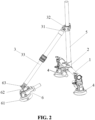
FIG. 2 is a schematic diagram of a vehicle camera bracket device according to some aspects of the present disclosure. -
FIG. 3 is a schematic diagram of a fixed component, an interface component, and a first suction component of the vehicle camera bracket device according to some aspects of the present disclosure. -
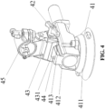
FIG. 4 is a schematic diagram of the first suction component according to some aspects of the present disclosure. -
FIG. 5 is a schematic diagram of the interface component according to some aspects of the present disclosure. -
- 101 - Photographic equipment ;
- 1 - Fixed component;
- 11 - Installation position;
- 2 - Interface component;
- 21 - Second fixed clamp;
- 22 - Locking clamp;
- 221 - Clamping groove;
- 2211 - Groove wall;
- 222 - First clamping block;
- 223 - Second clamping block;
- 224 - Motion gap;
- 225 - Clamping gap;
- 23 - Clamping locking piece;
- 3 - Supporting component;
- 31 - Supporting position;
- 32 - Supporting part;
- 33 - Telescopic rod;
- 4 - First suction component;
- 41 - First suction cup;
- 411 - Suction cup integrated module;
- 412 - Connector;
- 413 - Slider;
- 42 - Locking part;
- 43 - First clamping part;
- 431 - Clamping groove;
- 44 - Limiting device;
- 45 - First fixed clamp;
- 5 - External carrying component;
- 6 - Second suction component;
- 61 - Second suction cup;
- 62 - Second locking part;
- 63 - Second clamping part.
- To elucidate the purpose, technical solution, and aspects of the present disclosure, a detailed description is presented in conjunction with the accompanying drawings and embodiments. It is important to note that the specific embodiments outlined herein are intended solely for explanatory purposes and do not serve to limit the scope of the present disclosure.
- Referring to
FIGs. 1-4 , a vehicle camera bracket device, as depicted in this embodiment, comprises a fixedcomponent 1 and a supportingcomponent 3. The fixedcomponent 1 is outfitted with a first suction component (e.g., two suction components 4), designed for secure attachment to the vehicle. With a designatedinstallation position 11, the fixedcomponent 1 facilitates the mounting ofphotographic equipment 101. On one end (a first end), the supportingcomponent 3 is equipped with a supportingposition 31, linking to anexternal carrying component 5. The opposing end (a second end) of the supportingcomponent 3, distanced from theexternal carrying component 5, is flexibly (e.g., movably and/or pivotably) connected to asecond suction component 6, providing support for thephotographic equipment 101 affixed to theexternal carrying component 5. - During usage, the
external carrying component 5, accommodating thephotographic equipment 101, can be affixed to theinstallation position 11 of the fixedcomponent 1. Thefirst suction component 4 ensures the stable attachment of the fixedcomponent 1 to the vehicle, enabling secure mounting of thephotographic equipment 101. Additionally, the selective (e.g., adjustable) positioning of thesecond suction component 6 enhances adherence. The supportingcomponent 3 is then inclined and linked to theexternal carrying component 5, delivering support and stability to thephotographic equipment 101. This setup guarantees the steadfast installation ofphotographic equipment 101, minimizing the likelihood of camera shake, and rendering it suitable for diverse vehicular recording scenarios, including crosswind conditions and uneven road surfaces. In some aspects, the aforementionedexternal carrying component 5 can be a rod designed for action cameras. - In this embodiment, one end (a first end) of the
interface component 2 establishes a connection with theinstallation position 11 of the fixedcomponent 1, while the opposite end (a second end) is designated for the installation of theexternal carrying component 5, which serves the purpose of carrying thephotographic equipment 101, thereby ensuring its secure fixation to theinstallation position 11 of the fixedcomponent 1. - In some examples, there are multiple
first suction components 4. In this embodiment, twofirst suction components 4 are detachably affixed to the respective ends of the fixedcomponent 1, with theinterface component 2 interposed between the two first suction components. Bothfirst suction components 4 situated at the respective ends of the fixedcomponent 1 can be rotatable (in one or more directions) for angle adjustment. This design enables the vehicle camera bracket device to adhere firmly to the vehicle surface through thesecond suction component 6 and the twofirst suction components 4, forming a stable triangular configuration to further enhance bracket stability for installation. - The
first suction component 4 includes afirst locking part 42, afirst clamping part 43, afirst suction cup 41, and a firstfixed clamp 45. One end of the firstfixed clamp 45 is connected with the end of the fixedcomponent 1, and its other end is flexibly connected to thefirst clamping part 43. Rotation of the firstfixed clamp 45 relative to thefirst clamping part 43 facilitates the adjustment of the angle of thefirst suction cup 41. Thefirst clamping part 43 can securely grasp thefirst suction cup 41, and the first lockingpart 42, positioned movably on thefirst clamping part 43, either releases or secures thefirst suction cup 41 based on its rotational movement relative to thefirst clamping part 43. - Similarly, the
second suction component 6 includes asecond suction cup 61, asecond locking part 63, and asecond clamping part 62. The movable connection of one end (a first end) of thesecond clamping part 62 to the supportingcomponent 3 allows for the adjustment of the angle of thesecond suction cup 61, which is clamped by the other end (a second end) by rotating thesecond clamping part 62 relative to the supportingcomponent 3. Thesecond locking part 63, movably situated on thesecond clamping part 62, serves to release or secure thesecond suction cup 61 based on rotational adjustments relative to thesecond clamping part 62. The interconnection dynamics among thesecond suction cup 61, thesecond locking part 63, and thesecond clamping part 62 mirror those of the first lockingpart 42, thefirst clamping part 43, and thefirst suction cup 41. - Regarding this application, in the event of a need to replace the
first suction cup 41 or thesecond suction cup 61 within thefirst suction component 4 or thesecond suction component 6, respectively, loosening the first lockingpart 42 or thesecond locking part 63 facilitates the swift removal of the suction cups for replacement. In summary, the disassembly process for thefirst suction cup 41 or thesecond suction cup 61 is characterized by its simplicity, convenience, and expediency. - Both the
first suction cup 41 and thesecond suction cup 61 incorporate a suction cup integratedmodule 411 and aconnector 412. One end (a first end) of theconnector 412 is linked to the suction cup integratedmodule 411, while the opposite side (a second end) features aslider 413. Thefirst clamping part 43 and thesecond clamping part 62 are each equipped with clampinggrooves 431, within which theslider 413 can move (e.g., sliding). The lockingpart 42 exhibits movable characteristics relative to the clampingpart 43, securing theconnector 412 within the clampinggrooves 431. - In some aspects, the vehicle camera bracket device can integrate multiple limiting
components 44, for example, with two such components elastically (or retractably) attached to both ends of theslider 413. These limitingcomponents 44 extend from the surface of theslider 413, serving to restrict the movement of the clampingpart 43. This preventive measure ensures that the clampingpart 43 remains secured to theslider 413, preventing unintended detachment when the lockingpart 42 is not engaged. The limitingcomponents 44 adopt an elastic (or retractable) design, allowing compression into theslider 413 upon application of external force and subsequently springing back into a limiting position in the absence of force (e.g., force applied on the limitingcomponent 44 forcing it into a retracted position). - In some aspects, the
interface component 2 features a secondfixed clamp 21 and a lockingclamp 22. The secondfixed clamp 21 securely fastens to theinstallation position 11 of the fixedcomponent 1, demonstrating adaptability to various fixedcomponent 1 models. Incorporating a clampinggroove 221 on its side surface, the secondfixed clamp 21 provides support for the end of theexternal carrying component 5. The lockingclamp 22 is affixed to thegroove wall 2211 of the clampinggroove 221, facilitating the secure clamping ofphotographic equipment 101. - The locking
clamp 22 comprises afirst clamping block 222 and asecond clamping block 223, fixed or hinged at one end each. The opposite ends of thefirst clamping block 222 and thesecond clamping block 223 are detachably connected, creating amotion gap 224. Both thefirst clamping block 222 and thesecond clamping block 223 are affixed to thegroove wall 2211, establishing aclamping gap 225 between the detachable connection location of these two clamping blocks and thegroove wall 2211. - This design provides the locking
clamp 22 with a degree of deformation, ensuring a secure grip on theexternal carrying component 5 and thereby maintaining the stability of the vehicle camera bracket device during shooting. - In some aspects, the
interface component 2 can be equipped with aclamping locking device 23. Theclamping locking device 23 sequentially passes through the opposite ends of thefirst clamping block 222 and thesecond clamping block 223, adjusting the size of themotion gap 224 by twisting (or rotating) theclamping locking device 23. This mechanism facilitates adaptation toexternal carrying components 5 of varying thicknesses by securing the carrying component within the clampinggroove 221 using thefirst clamping block 222 and thesecond clamping block 223. - In one example, the
clamping locking device 23 adopts a conventional hand-twist structure. - Furthermore, for ease of direction adjustment during shooting or modification of the suction position of the
second suction component 6, both ends of the supportingcomponent 3 can be flexibly (e.g., pivotably, rotatably) connected to theexternal carrying component 5 and thesecond suction component 6, respectively. - In some aspects, the supporting
component 3 takes the form of rod (e.g., a telescopic rod). For instance, when it is necessary to maintain the position of theexternal carrying component 5 unchanged but alter the position of thesecond suction component 6, the rod can be extended or retracted. For example, the rod can be then rotated relative to the fixed clamp of the camera, enabling thesecond suction component 6 to reattach to the appropriate position. - In some aspects, the supporting
component 3 comprises atelescopic rod 33 and a supportingpart 32, with the supportingposition 31 situated on thetelescopic rod 33. The supportingpart 32 is flexibly (e.g., rotatably, pivotably, etc.) connected to the supportingposition 31 of thetelescopic rod 33. The end of thetelescopic rod 33, distanced from the supportingpart 32, can be movably (e.g., rotatably, pivotably, etc.) connected to thesecond suction component 6. The supportingpart 32 can serve the purpose of supporting the photographic equipment 101 (not shown) on theexternal carrying component 5. - Specifically, when the objective is to maintain the position of the
external carrying component 5 unaltered while adjusting the position of thesecond suction component 6, thetelescopic rod 33 can be extended or retracted. The rod is then rotated relative to the supportingpart 32, enabling thesecond suction component 6 to reattach to the appropriate position. - The foregoing represents only an exemplary embodiment of the present disclosure and is not intended to restrict its scope. Any modifications, equivalent replacements, and enhancements made within the spirit and principles of the present disclosure should be encompassed within the protective scope of the present disclosure.
Claims (10)
- A vehicle camera bracket device, comprising:a fixed component, equipped with an installation position for mounting photographic equipment, and comprising a first suction component; anda supporting component, with a first end, incorporation with the fixed component, set up to support the photographic equipment, and a second end hosting a second suction component.
- A vehicle camera bracket device according to claim 1, wherein the first suction component comprises two first suction components that are rotatably set at respective ends of the fixed component.
- A vehicle camera bracket device according to any preceding claim, wherein the first suction component comprises a first locking part, a first clamping part, a first suction cup, and a first fixed clamp;a first end of the first fixed clamp is connected with the fixed component, and a second end of the first fixed clamp is movably connected to the first clamping part, which clamps the first suction cup;the first locking part is movably set on the first clamping part; andthe first locking part is configured to relax or lock the first suction cup by rotating relative to the first clamping part.
- A vehicle camera bracket device according to any preceding claim, wherein the second suction component comprises a second suction cup, a second locking part, and a second clamping part;a first end of the second clamping part is movably connected to the supporting component, and a second end of the second clamping part clamps to the second suction cup;the second locking part is movably set on the second clamping part; and the second locking part is configured to relax or lock the second suction cup by rotating relative to the second clamping part.
- A vehicle camera bracket device according to claim 4 when dependent on claim 3, wherein each of the first suction cup and the second suction cup comprises a suction cup integrated module and a connector;a first side of the connector is connected to the suction cup integrated module, and a second side of the connector is equipped with a slider; andeach of the first clamping part and the second clamping part comprises a clamping groove, and the slider is movably set in the clamping groove.
- A vehicle camera bracket device according to claim 2 or according to claims 3-5 when dependent on claim 2, further comprising an interface component,
wherein the interface component is located between the two first suction components, a first end of the interface component installed at the installation position of the fixed component and a second end of the interface component adapted to connect the photographic equipment to fix the photographic equipment to the installation position of the fixed component. - A vehicle camera bracket device according to claim 6, wherein the interface component comprises a second fixed clamp and a locking clamp;the second fixed clamp is clamped to the fixed component and comprises a clamping groove on a side for carrying the photographic equipment; andthe locking clamp is fixed to a groove wall of the clamping groove to clamp the photographic equipment.
- A vehicle camera bracket device according to claim 7, wherein the locking clamp comprises a first clamping block and a second clamping block;a first end of the first clamping block is fixed to a first end of the second clamping block;a second end of the first clamping block is detachably connected to a second end of the second clamping block, forming a motion gap; andthe first clamping block and the second clamping block are both connected to the groove wall, and the detachable connection between the first clamping block and the second clamping block forms a clamping gap with the groove wall.
- A vehicle camera bracket device according to claim 8, wherein the interface component comprises a clamping locking piece;
the clamping locking piece successively moves through the second end of the first clamping block and the second end of the second clamping block, and is configured to adjust the size of the motion gap. - A vehicle camera bracket device according to any preceding claim, the supporting component comprises a telescopic rod and a supporting part, a supporting position is set on the telescopic rod, and the supporting part is movably connected to the supporting position of the telescopic rod, an end of the telescopic rod, away from the supporting part, is movably connected to the second suction component, and the supporting part is used to support the photographic equipment.
Applications Claiming Priority (1)
| Application Number | Priority Date | Filing Date | Title |
|---|---|---|---|
| CN202322226815.9U CN220842395U (en) | 2023-08-17 | 2023-08-17 | A car photography bracket device |
Publications (1)
| Publication Number | Publication Date |
|---|---|
| EP4509752A1 true EP4509752A1 (en) | 2025-02-19 |
Family
ID=90788057
Family Applications (1)
| Application Number | Title | Priority Date | Filing Date |
|---|---|---|---|
| EP24184491.9A Pending EP4509752A1 (en) | 2023-08-17 | 2024-06-25 | Vehicle camera bracket device |
Country Status (3)
| Country | Link |
|---|---|
| US (1) | US20250058723A1 (en) |
| EP (1) | EP4509752A1 (en) |
| CN (1) | CN220842395U (en) |
Families Citing this family (3)
| Publication number | Priority date | Publication date | Assignee | Title |
|---|---|---|---|---|
| CN220842394U (en) * | 2023-08-17 | 2024-04-26 | 深圳市铁头科技有限公司 | A kind of adsorption structure that is easy to disassemble and assemble |
| USD1099205S1 (en) * | 2023-09-26 | 2025-10-21 | Tilta Inc. | Camera mount kit |
| USD1104121S1 (en) * | 2024-03-29 | 2025-12-02 | Shenzhen Leqi Innovation Co., Ltd. | Support device for camera |
Citations (4)
| Publication number | Priority date | Publication date | Assignee | Title |
|---|---|---|---|---|
| US7320450B2 (en) * | 2003-10-31 | 2008-01-22 | Carnevali Jeffrey D | Configurable mounting apparatus |
| US20120018599A1 (en) * | 2010-07-26 | 2012-01-26 | Wen-Feng Tsai | Multi-vacuum mount type support device |
| CN205905910U (en) * | 2016-08-09 | 2017-01-25 | 南宁胜贤影视科技有限公司 | On -vehicle sucking disc tripod |
| CN108562316A (en) * | 2018-01-10 | 2018-09-21 | 中国矿业大学 | A kind of adaptive six degree of freedom sensor fixed platform of pneumatic type and its control method |
Family Cites Families (4)
| Publication number | Priority date | Publication date | Assignee | Title |
|---|---|---|---|---|
| US9958759B2 (en) * | 2012-03-08 | 2018-05-01 | Really Right Stuff, Llc | Adaptable camera support |
| KR20150075342A (en) * | 2014-02-28 | 2015-07-03 | 주식회사 세나테크놀로지 | Fixing apparatus for camera |
| US10479288B2 (en) * | 2016-08-05 | 2019-11-19 | MotoCrane, LLC | Releasable vehicular camera mount |
| US11162632B2 (en) * | 2017-06-02 | 2021-11-02 | James Harrison Elias | Tripod stabilizing base |
-
2023
- 2023-08-17 CN CN202322226815.9U patent/CN220842395U/en active Active
-
2024
- 2024-03-13 US US18/604,256 patent/US20250058723A1/en active Pending
- 2024-06-25 EP EP24184491.9A patent/EP4509752A1/en active Pending
Patent Citations (4)
| Publication number | Priority date | Publication date | Assignee | Title |
|---|---|---|---|---|
| US7320450B2 (en) * | 2003-10-31 | 2008-01-22 | Carnevali Jeffrey D | Configurable mounting apparatus |
| US20120018599A1 (en) * | 2010-07-26 | 2012-01-26 | Wen-Feng Tsai | Multi-vacuum mount type support device |
| CN205905910U (en) * | 2016-08-09 | 2017-01-25 | 南宁胜贤影视科技有限公司 | On -vehicle sucking disc tripod |
| CN108562316A (en) * | 2018-01-10 | 2018-09-21 | 中国矿业大学 | A kind of adaptive six degree of freedom sensor fixed platform of pneumatic type and its control method |
Also Published As
| Publication number | Publication date |
|---|---|
| CN220842395U (en) | 2024-04-26 |
| US20250058723A1 (en) | 2025-02-20 |
Similar Documents
| Publication | Publication Date | Title |
|---|---|---|
| US20250058723A1 (en) | Vehicle camera bracket device | |
| US10865934B2 (en) | Mobile device mount | |
| US20130233986A1 (en) | Apparatus for supporting mobile phones, electronic tablets and cameras | |
| US20200169650A1 (en) | Apparatus for mounting of a camera or other components | |
| US5322255A (en) | Mounting bracket | |
| CN222334936U (en) | Bowl mouth cradle head converter and car is clapped and is put up | |
| CN212617321U (en) | Angle adjusting bracket | |
| CN210219149U (en) | Universal tripod head for intelligent camera support | |
| CN113048189B (en) | Shock attenuation head, on-vehicle shock attenuation arm and on-vehicle shooting equipment | |
| CN210135396U (en) | Multi-angle automatic regulating apparatus for camera | |
| CN201439855U (en) | Steadicam balancing pole device | |
| CN218762194U (en) | Locking structure and shooting device | |
| CN207897016U (en) | A kind of handset bracket for shooting micro- sem observation image | |
| CN212156385U (en) | Cloud platform with folding and horizontal rotation function | |
| CN206696575U (en) | a photographic component | |
| US11913596B2 (en) | Binocular/tripod adapter system | |
| CN221127348U (en) | A mobile phone camera holding device for microscope | |
| CN111412357A (en) | A pan-tilt with folding and horizontal rotation functions | |
| CN219453382U (en) | High-speed camera's installation cloud platform | |
| CN208935712U (en) | An external protection device for a PTZ camera | |
| CN224174940U (en) | Adjustable surveillance camera mounting bracket | |
| CN216243096U (en) | Support capable of keeping terminal stably clamped | |
| CN221068312U (en) | Patrol equipment support suitable for electric bicycle handlebar | |
| CN215155227U (en) | A bicycle seat cushion extension bracket | |
| CN221974948U (en) | A display camera bracket |
Legal Events
| Date | Code | Title | Description |
|---|---|---|---|
| PUAI | Public reference made under article 153(3) epc to a published international application that has entered the european phase |
Free format text: ORIGINAL CODE: 0009012 |
|
| STAA | Information on the status of an ep patent application or granted ep patent |
Free format text: STATUS: THE APPLICATION HAS BEEN PUBLISHED |
|
| AK | Designated contracting states |
Kind code of ref document: A1 Designated state(s): AL AT BE BG CH CY CZ DE DK EE ES FI FR GB GR HR HU IE IS IT LI LT LU LV MC ME MK MT NL NO PL PT RO RS SE SI SK SM TR |
|
| STAA | Information on the status of an ep patent application or granted ep patent |
Free format text: STATUS: REQUEST FOR EXAMINATION WAS MADE |
|
| 17P | Request for examination filed |
Effective date: 20250806 |
|
| STAA | Information on the status of an ep patent application or granted ep patent |
Free format text: STATUS: EXAMINATION IS IN PROGRESS |
|
| 17Q | First examination report despatched |
Effective date: 20260408 |