EP4509742A2 - Multi-port valve, water-side component, thermal management integrated system, and vehicle - Google Patents
Multi-port valve, water-side component, thermal management integrated system, and vehicle Download PDFInfo
- Publication number
- EP4509742A2 EP4509742A2 EP24193236.7A EP24193236A EP4509742A2 EP 4509742 A2 EP4509742 A2 EP 4509742A2 EP 24193236 A EP24193236 A EP 24193236A EP 4509742 A2 EP4509742 A2 EP 4509742A2
- Authority
- EP
- European Patent Office
- Prior art keywords
- port
- interface
- valve
- core
- water
- Prior art date
- Legal status (The legal status is an assumption and is not a legal conclusion. Google has not performed a legal analysis and makes no representation as to the accuracy of the status listed.)
- Pending
Links
Images







Classifications
-
- F—MECHANICAL ENGINEERING; LIGHTING; HEATING; WEAPONS; BLASTING
- F16—ENGINEERING ELEMENTS AND UNITS; GENERAL MEASURES FOR PRODUCING AND MAINTAINING EFFECTIVE FUNCTIONING OF MACHINES OR INSTALLATIONS; THERMAL INSULATION IN GENERAL
- F16K—VALVES; TAPS; COCKS; ACTUATING-FLOATS; DEVICES FOR VENTING OR AERATING
- F16K11/00—Multiple-way valves, e.g. mixing valves; Pipe fittings incorporating such valves
- F16K11/02—Multiple-way valves, e.g. mixing valves; Pipe fittings incorporating such valves with all movable sealing faces moving as one unit
- F16K11/08—Multiple-way valves, e.g. mixing valves; Pipe fittings incorporating such valves with all movable sealing faces moving as one unit comprising only taps or cocks
- F16K11/085—Multiple-way valves, e.g. mixing valves; Pipe fittings incorporating such valves with all movable sealing faces moving as one unit comprising only taps or cocks with cylindrical plug
- F16K11/0856—Multiple-way valves, e.g. mixing valves; Pipe fittings incorporating such valves with all movable sealing faces moving as one unit comprising only taps or cocks with cylindrical plug having all the connecting conduits situated in more than one plane perpendicular to the axis of the plug
-
- B—PERFORMING OPERATIONS; TRANSPORTING
- B60—VEHICLES IN GENERAL
- B60H—ARRANGEMENTS OF HEATING, COOLING, VENTILATING OR OTHER AIR-TREATING DEVICES SPECIALLY ADAPTED FOR PASSENGER OR GOODS SPACES OF VEHICLES
- B60H1/00—Heating, cooling or ventilating devices
- B60H1/00485—Valves for air-conditioning devices, e.g. thermostatic valves
-
- B—PERFORMING OPERATIONS; TRANSPORTING
- B60—VEHICLES IN GENERAL
- B60H—ARRANGEMENTS OF HEATING, COOLING, VENTILATING OR OTHER AIR-TREATING DEVICES SPECIALLY ADAPTED FOR PASSENGER OR GOODS SPACES OF VEHICLES
- B60H1/00—Heating, cooling or ventilating devices
- B60H1/32—Cooling devices
- B60H1/3204—Cooling devices using compression
- B60H1/3228—Cooling devices using compression characterised by refrigerant circuit configurations
- B60H1/32284—Cooling devices using compression characterised by refrigerant circuit configurations comprising two or more secondary circuits, e.g. at evaporator and condenser side
-
- B—PERFORMING OPERATIONS; TRANSPORTING
- B60—VEHICLES IN GENERAL
- B60K—ARRANGEMENT OR MOUNTING OF PROPULSION UNITS OR OF TRANSMISSIONS IN VEHICLES; ARRANGEMENT OR MOUNTING OF PLURAL DIVERSE PRIME-MOVERS IN VEHICLES; AUXILIARY DRIVES FOR VEHICLES; INSTRUMENTATION OR DASHBOARDS FOR VEHICLES; ARRANGEMENTS IN CONNECTION WITH COOLING, AIR INTAKE, GAS EXHAUST OR FUEL SUPPLY OF PROPULSION UNITS IN VEHICLES
- B60K11/00—Arrangement in connection with cooling of propulsion units
- B60K11/02—Arrangement in connection with cooling of propulsion units with liquid cooling
-
- F—MECHANICAL ENGINEERING; LIGHTING; HEATING; WEAPONS; BLASTING
- F16—ENGINEERING ELEMENTS AND UNITS; GENERAL MEASURES FOR PRODUCING AND MAINTAINING EFFECTIVE FUNCTIONING OF MACHINES OR INSTALLATIONS; THERMAL INSULATION IN GENERAL
- F16K—VALVES; TAPS; COCKS; ACTUATING-FLOATS; DEVICES FOR VENTING OR AERATING
- F16K27/00—Construction of housing; Use of materials therefor
- F16K27/06—Construction of housing; Use of materials therefor of taps or cocks
- F16K27/065—Construction of housing; Use of materials therefor of taps or cocks with cylindrical plugs
-
- B—PERFORMING OPERATIONS; TRANSPORTING
- B60—VEHICLES IN GENERAL
- B60K—ARRANGEMENT OR MOUNTING OF PROPULSION UNITS OR OF TRANSMISSIONS IN VEHICLES; ARRANGEMENT OR MOUNTING OF PLURAL DIVERSE PRIME-MOVERS IN VEHICLES; AUXILIARY DRIVES FOR VEHICLES; INSTRUMENTATION OR DASHBOARDS FOR VEHICLES; ARRANGEMENTS IN CONNECTION WITH COOLING, AIR INTAKE, GAS EXHAUST OR FUEL SUPPLY OF PROPULSION UNITS IN VEHICLES
- B60K1/00—Arrangement or mounting of electrical propulsion units
- B60K2001/003—Arrangement or mounting of electrical propulsion units with means for cooling the electrical propulsion units
Definitions
- This application relates to the field of thermal management technologies, and in particular, to a multi-port valve, a water-side component, a thermal management integrated system, and a vehicle.
- a multi-port valve in a related technology includes a valve body and a valve core.
- An outer circumferential surface of the valve core is provided with several grooves, and water connection ports for communicating with the grooves are disposed on the valve body.
- a path may be formed through the groove and the two water connection ports, which causes a small circumferential interval between the two water connection ports. Consequently, a fluid needs to pass through a small curve when flowing in the path, and flow resistance of the fluid is large, which is not conducive to transport efficiency of the fluid.
- Embodiments of this application provide a multi-port valve, a water-side component, a thermal management integrated system, and a vehicle, to reduce flow resistance of the multi-port valve.
- an embodiment of this application provides a multi-port valve, including a valve body and a valve core.
- the valve core is located in an accommodation cavity of the valve body and is rotatably connected to the valve body, a rotation center line of the valve core is an axis line, a first interface and a second interface that communicate with each other through the vacant cavity are disposed on the valve body, the first interface and the second interface are distributed on two opposite sides of the axis line,
- the valve core includes a first port, a second port, and a first channel that communicates the first port with the second port, the first channel penetrates the valve core, a part of the axis line is located in the first channel, the first port can communicate with the first interface, and the second port can communicate with the second interface.
- the first port when the valve core is rotated, the first port can communicate with the first interface, and the second port can communicate with the second interface, to form a path.
- the first interface and the second interface are distributed on the two opposite sides of the axis line, to increase an interval between the first interface and the second interface in an axial direction of the valve body, so as to prevent a first medium (for example, water) flowing in the valve core from flowing through a sharp curve at a small angle. Therefore, this can effectively reduce flow resistance, and improve transmission efficiency.
- a first medium for example, water
- the first channel penetrates the valve core, and a part of the axis line is located in the first channel, a length of the first channel can be effectively reduced. This can save a limited volume of the valve core, and effectively reduce flow resistance.
- the first channel penetrates the valve core along a radial direction of the valve core, and the radial direction of the valve core is perpendicular to an extension direction of the axis line. Because the first channel penetrates the valve core along the radial direction of the valve core, the first channel is a straight-through channel from the first port to the second port. This can effectively reduce flow resistance of the first medium during flowing in the first channel, increase a flow velocity of the first medium, and further improve efficiency of transporting the first medium.
- the first channel may alternatively penetrate the valve core along a direction inclined relative to a radial direction of the valve core, and the radial direction of the valve core is perpendicular to an extension direction of the axis line.
- the first medium flows in the first channel. This can also reduce flow resistance, and improve transmission efficiency of the first medium.
- the first channel includes a first segment and an intermediate segment that are connected in sequence, the first port is located at an end that is of the first segment and that is far away from the intermediate segment, a part of the axis line is located in the intermediate segment, a diameter of the intermediate segment is less than a diameter of the first port, and the first segment gradually extends in a direction in which the intermediate segment faces the first port. Because the first segment gradually extends in the direction from the intermediate segment to the first port, when the first medium entering from the first port passes through the first segment, the first segment can play a guiding role, to lead the first medium into the intermediate segment. In addition, the diameter of the intermediate segment is smaller, to accelerate a flow velocity of the first medium in the intermediate segment.
- the diameter of the first port is large, so that the first segment can be easily connected to a water connection port of the valve body.
- a size of the intermediate segment of the first channel is small, and the first segment gradually extends in the direction in which the intermediate segment faces the first port, space is reserved for opening another groove or channel at a same layer of the valve core. This optimizes a size of a channel part or a groove part at the same layer, to ensure normal liquid flowing.
- the first channel further includes a second segment, the first segment, the intermediate segment, and the second segment are connected in sequence, the second port is located at an end that is of the second segment and that is far away from the intermediate segment, the diameter of the intermediate segment is less than a diameter of the second port, and the second segment gradually extends in a direction in which the intermediate segment faces the second port.
- space can also be reserved for opening another groove or channel at a same layer of the valve core. This optimizes a size of a channel part or a groove at the same layer, to ensure normal liquid flowing.
- the valve core includes a first core part and a second core part, the first core part and the second core part are arranged along the extension direction of the axis line, the first port, the second port, and the first channel are located in the first core part, a third port, a fourth port, and a second channel that communicates the third port with the fourth port are disposed on the second core part, the second channel penetrates the valve core, a part of the axis line is located in the second channel, a third interface and a fourth interface are disposed at positions that are of the valve body and that correspond to the second core part, the third interface and the fourth interface are distributed on the two opposite sides of the axis line, the third interface can communicate with the third port, and the fourth interface can communicate with the fourth port.
- a size of the first port is greater than a size of the third port, so that in a status in which the first channel communicates the first interface with the second interface, the second core part has a first status and a second status, the second channel communicates the third interface with the fourth interface in the first status, and the second channel does not communicate the third interface with the fourth interface in the second status. Because the size of the first port is greater than the size of the third port, and a size of the second port is greater than a size of the fourth port, the valve core in this implementation can generate at least two modes.
- the second core part is in the first status, the first port communicates with the first interface, the second port communicates with the second interface, the third port communicates with the third interface, and the fourth port communicates with the fourth interface.
- the first port communicates with the second port, and the third port communicates with the fourth port, to form two independent flow channels to be communicated with an external flow channel or component.
- the second core part is in the second status, the first port communicates with the first interface, the second port communicates with the second interface, the third port does not communicate with the third interface, and the fourth port does not communicate with the fourth interface. In this case, only one flow channel is connected.
- the first port does not communicate with the first interface
- the second port does not communicate with the second interface
- the third port does not communicate with the third interface
- the fourth port does not communicate with the fourth interface.
- the multi-port valve in this implementation has different modes, so that the multi-port valve can implement multi-way control.
- the valve core includes a plurality of layers of core parts, and the first core part and the second core part are core parts at two adjacent layers. Different modes may be generated through cooperation between the first core part and the second core part.
- the first core part and the second core part form one core structure unit
- the valve core includes at least two core structure units
- the at least two core structure units are arranged in a stacked manner along the extension direction of the axis line. More use modes can be generated through cooperation between a plurality of core structures.
- sizes of the first interface, the second interface, the third interface, and the fourth interface each are less than or equal to the size of the third port. Therefore, the first port, the second port, the third port, and the fourth port can all be completely communicated with the first interface and the second interface. In other words, the first interface, the second interface, the third interface, and the fourth interface all can completely fall within regions corresponding to the first port, the second port, the third port, and the fourth port.
- the first core part is provided with a first groove
- the second core part is provided with a second groove
- the first groove can communicate with the first interface or the second interface
- the second groove can communicate with the third interface or the fourth interface
- the first groove and the second groove at least partially face each other in the extension direction of the axis line
- the valve core is provided with a first through hole configured to communicate the first groove with the second groove.
- the first groove cooperates with the second groove, to generate a new communication manner, so as to generate a new mode to adapt to different requirements.
- the first through hole extends along the extension direction of the axis line, to communicate the first groove with the second groove in the extension direction of the axis line. Because the first through hole extends along the extension direction of the axis line, the first through hole is a straight through hole. When the first medium flows from the first groove to the second groove, or flows from the second groove to the first groove, flow resistance of the first medium passing through the first through hole is reduced, to improve transmission efficiency of the first medium in the first through hole.
- each second core part has a plurality of second grooves, and the plurality of second grooves on the two second core parts are in a one-to-one correspondence in the extension direction of the axis line. Because the plurality of second grooves on the two second core parts are in a one-to-one correspondence in the extension direction of the axis line, processing difficulty can be reduced during processing, and an overall structure of the valve core can be regular, thereby improving a force balance of the valve core.
- the two second core parts are provided with third grooves, the two third grooves face the first channel in the extension direction of the axis line, the valve core is provided with a second through hole, and the second through hole is configured to communicate the two third grooves with each other.
- the second through hole is configured to communicate the two third grooves with each other, to generate a new communication manner, so as to generate a new mode to adapt to different requirements.
- a proportionally adjustable port is disposed on the valve body, in a circumferential direction of the valve core, the proportionally adjustable port is adjacent to the first interface and/or the second interface, the proportionally adjustable port can communicate with the first port or the second port, and the proportionally adjustable port, and the first interface and/or the second interface can communicate with the corresponding first port and/or the corresponding second port.
- the proportionally adjustable port is adjacent to the first interface and/or the second interface, the proportionally adjustable port, the first interface, and the second interface can communicate with the first port or the second port, to implement proportional adjustment of flows of the first port and the second port.
- the valve core includes a plurality of core parts that are sequentially arranged along the extension direction of the axis line, the first port, the second port, and the first channel are disposed on one of the core parts, and at least one of the core parts can rotate relative to another core part. Because at least one of the core parts can rotate relative to another core part, the valve core in this embodiment can generate more use modes for usage in a solution that requires a plurality of paths.
- an embodiment of this application provides a water-side component.
- the water-side component includes a water path substrate and a multi-port valve
- the water path substrate includes a bottom plate, a top plate, and a connection plate that connects the bottom plate to the top plate, and the bottom plate and the top plate are disposed opposite to each other at an interval.
- a receptacle is enclosed with the bottom plate, the top plate, and the connection plate
- the multi-port valve is disposed in the receptacle and is located between the top plate and the bottom plate
- the multi-port valve includes a plurality of water connection ports.
- a plurality of first external connection ports are disposed on the top plate, a plurality of second external connection ports are disposed on the bottom plate, the plurality of first external connection ports are separately communicated with some of the plurality of water connection ports, and the plurality of second external connection ports are separately communicated with some of the plurality of water connection ports.
- a flow channel of the water path substrate may be disposed around the multi-port valve, so that the flow channel of the water path substrate is three-dimensional. This can effectively use three-dimensional space, reduce a size in a direction, and facilitate miniaturization of the water-side component.
- the flow channel of the water path substrate is three-dimensional, to reduce design difficulty of the flow channel, and further reduce bending of the flow channel, thereby reducing flow resistance in the flow channel.
- a plurality of flow channels are disposed on the water path substrate, the plurality of flow channels are configured to communicate the plurality of first external connection ports with the plurality of corresponding water connection ports, and communicate the plurality of second external connection ports with the plurality of corresponding water connection ports, some of the flow channels are formed on the top plate, some of the flow channels are formed on the bottom plate, and some of the flow channels are configured to communicate the flow channel on the top plate with the flow channel on the bottom plate. Because some flow channels are located on the top plate, some flow channels are located on the bottom plate, and some flow channels are configured to communicate the flow channels on the top plate with the flow channels on the bottom plate, a 3D structure of flow channels is formed. This can effectively use three-dimensional space, reduce a quantity of flow channels disposed on the bottom plate, reduce a size of the bottom plate, reduce difficulty in arranging the flow channels, and facilitate a miniaturization design of the water-side component.
- the some of the flow channels between the top plate and the bottom plate are arc-shaped and extend outside a periphery of the multi-port valve. Because the some of the flow channels are arc-shaped and extend outside the periphery of the multi-port valve, the flow channels can be effectively attached to the periphery of the multi-port valve, to improve design compactness of the flow channels, and facilitate the miniaturization design of the water-side component.
- some of the plurality of water connection ports are first interfaces, some of the plurality of water connection ports are second interfaces, the first interface is located at a position that is of the multi-port valve and that faces the top plate, and the second interface is located at a position that is of the multi-port valve and that faces the bottom plate. Because the first interface is located at the position that is of the multi-port valve and that faces the top plate, and the second interface is located at the position that is of the multi-port valve and that faces the bottom plate, the first interface is close to the first external connection port located on the top plate, and the second interface is close to the second external connection port located on the bottom plate.
- the first interface and the second interface are located on two opposite sides in a first direction, some flow channels need to be located on the top plate, and some flow channels need to be located on the bottom plate, to fully utilize the three-dimensional space, so as to implement the miniaturization design.
- the multi-port valve includes a valve body and a valve core, the valve core is located in an accommodation cavity of the valve body and is rotatably connected to the valve body, and a rotation center line of the valve core is an axis line.
- the first interface and the second interface that communicate with each other through the vacant cavity are disposed on the valve body, and the first interface and the second interface are distributed on two opposite sides of the axis line.
- the valve core includes a first port, a second port, and a first channel that communicates the first port with the second port, the first channel penetrates the valve core, a part of the axis line is located in the first channel, the first port can communicate with the first interface, and the second port can communicate with the second interface.
- connection plate includes a first plate, the first plate is located between the top plate and the bottom plate in the first direction, the first direction is a direction in which the top plate and the bottom plate are arranged,
- the water-side component further includes a water pump, the water pump is disposed on a side that is of the first plate and that is away from the bottom plate, and an outlet and an inlet of the water pump directly communicate with the flow channel. Because the water pump is disposed on the side that is of the first plate and that is away from the bottom plate, and the first plate is located between the top plate and the bottom plate in the first direction, the three-dimensional space can be effectively used, to effectively improve miniaturization of the water-side component.
- an embodiment of this application provides a thermal management module, including a refrigerant component, a heat exchanger, and the water-side component in the first aspect.
- a first medium flowing in the water-side component and a second medium flowing in the refrigerant component perform heat exchange by using the heat exchanger.
- an embodiment of this application provides a thermal management system, including a refrigerant component, a heat exchanger, the water-side component in the first aspect.
- a first medium flowing in the water-side component and a second medium flowing in the refrigerant component perform heat exchange by using the heat exchanger.
- an embodiment of this application provides a thermal management system, including a water tank, a gas-liquid separator, and the thermal management integrated module in the third aspect.
- the thermal management integrated module is connected to the water tank and the gas-liquid separator through a coolant hose.
- an embodiment of this application provides a vehicle, including a battery, a powertrain, and the thermal management integrated system in the fifth aspect.
- the thermal management integrated system is configured to perform thermal management on the battery and the powertrain.
- this application provides an energy storage system, including an energy storage battery and the thermal management system in the fifth aspect.
- the thermal management system is configured to perform thermal management on the energy storage battery.
- Perpendicularity defined in this application is not limited to an absolute perpendicular intersection (an included angle is 90 degrees) relationship, a non-absolute perpendicular intersection relationship caused by factors such as an assembly tolerance, a design tolerance, and a structural flatness is allowed, and an error within a small angle range is allowed. For example, a relationship within an assembly angle range of 80 degrees to 100 degrees may be understood as the perpendicular relationship.
- Parallelism defined in this application is not limited to absolute parallelism.
- the definition of parallelism may be understood as basic parallelism, and non-absolute parallelism caused by factors such as an assembly tolerance, a design tolerance, and a structure flatness is allowed.
- the factors may cause a case in which a sliding cooperation part and a first door plate are not absolutely parallel, but this application also defines, as parallelism, the case in which the sliding cooperation part and the first door plate are not absolutely parallel.
- An embodiment of this application provides a thermal management system.
- the thermal management system in embodiments of this application is applicable to the vehicle-mounted field and the energy storage field.
- the thermal management system in embodiments of this application may be used in an electric vehicle in the vehicle-mounted field, and the electric vehicle is transport driven by an electric power module.
- the electric power module may include, for example, a power distribution unit (PDU), a microcontroller unit (MCU), mapped diagnostic context (MDC), and a motor.
- the thermal management system in embodiments of this application may be used in a photovoltaic system and a wind power system in the energy storage field.
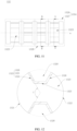
- FIG. 1a is a diagram of a structure of a vehicle 1000 according to an embodiment of this application.
- FIG. 1b is an operating block diagram of a thermal management system 1 of the vehicle 1000 according to an embodiment of this application.
- the vehicle 1000 includes the thermal management system 1 and a thermal management object 2.
- the thermal management system 1 is configured to perform thermal management on the thermal management object 2. It may be understood that positions of the thermal management object 2 and the thermal management system 1 in the figure are merely examples, and do not indicate that the thermal management object 2 and the thermal management system 1 need to be located in the positions shown in the figure.
- the thermal management object 2 and the thermal management system 1 may alternatively be disposed at other positions.
- the thermal management object 2 includes one or more of a battery, a powertrain, and an electronic control module.
- the battery is configured to provide most of electric energy required by the vehicle 1000.
- the powertrain is configured to provide power for the vehicle 1000, and the powertrain may include a motor, a transmission, a drive system, and an exhaust system.
- the electronic control module is an overall system including elements such as an electronic control unit (ECU), a harness, and a sensor that are of the vehicle, and the electronic control module may perform refined adjustment, control, and management on an automotive engine, the transmission, braking, and security control, to ensure smooth driving and stability of the vehicle in various complex driving scenarios.
- the electronic control module of the vehicle is an important part of the vehicle, and has high requirements on matching, debugging, maintenance, upgrading, and the like of an electronic device.
- the thermal management system 1 is configured to monitor and control a temperature of the vehicle 1000, and maintain a normal operating temperature range of each part (for example, the battery, the powertrain, the electronic control module, and an interior of the vehicle) of the vehicle 1000, to improve performance, efficiency, and comfort of the vehicle 1000.
- a normal operating temperature range of each part for example, the battery, the powertrain, the electronic control module, and an interior of the vehicle
- the thermal management system 1 includes a thermal management integrated module 11, a water tank 12, and a gas-liquid separator 13.
- the water tank 12 is configured to provide circulated water for the thermal management integrated module 11. Because the water tank 12 is independent of the thermal management integrated module 11 and is connected to the thermal management integrated module 11 through a coolant hose, a position of the water tank 12 may be decoupled from a position of the thermal management integrated module 11. For example, the water tank 12 is placed at a higher position, and the thermal management integrated module 11 is placed at a lower position than the water tank 12. This can improve use performance of the water tank 12 and the thermal management integrated module 11, and further enable the thermal management integrated module 11 in this embodiment to be adapted to different environments, for example, the thermal management integrated module 11 may be used in the vehicle 1000 and the energy storage system. In addition, the water tank 12 and the thermal management integrated module 11 are separately and independently disposed. Therefore, the thermal management integrated module 11 is not affected by the water tank 12 with a large volume, to facilitate miniaturization of the thermal management integrated module 11.
- a component with a large volume like the gas-liquid separator 13 may also be independent of the thermal management integrated module 11, and is connected to the thermal management integrated module 11 through a coolant hose, to facilitate miniaturization of the thermal management integrated module 11.
- a compressor 14 in the thermal management system 1 may also be disposed independently of the thermal management integrated module 11. Certainly, in some implementations, the compressor 14 may alternatively be integrated into the thermal management integrated module 11.
- FIG. 2 is an operating block diagram of a thermal management system 1 of an energy storage system 2000 according to an embodiment of this application.
- the energy storage system 2000 includes the thermal management system 1 and the thermal management object 2, and the thermal management system 1 includes a thermal management integrated module 11, a water tank 12, and a gas-liquid separator 13.
- the thermal management integrated module 11, the water tank 12, and the gas-liquid separator 13, refer to the foregoing embodiment in FIG. 1b . Details are not described herein again.
- the thermal management object 2 in this embodiment is an energy storage battery, a power control system (PCS), a DC-DC converter, and the like.
- FIG. 3 is a diagram of a structure of the thermal management integrated module 11 according to an embodiment of this application.
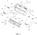
- FIG. 4 is an exploded diagram of the thermal management integrated module 11 in FIG. 3 .
- the thermal management integrated module 11 in this embodiment may be used in the thermal management system 1 in embodiments in FIG. 1b and FIG. 2 , or maybe used in another thermal management system 1, for example, a thermal management system 1 in the electronic and medical fields.
- the thermal management integrated module 11 includes a water-side component 100, a refrigerant component 200, and a heat exchanger 300.
- the water-side component 100 in this embodiment is mainly configured to adjust and control flowing of a first medium in the system, to ensure normal operation of the device and temperature control.
- the first medium in the water-side component 100 may flow to positions such as the battery, the powertrain, and a control unit, to implement temperature control and adjustment on the battery, the powertrain, the control unit, and the like.
- the refrigerant component 200 in this embodiment is mainly configured to control a refrigerant to circulate in the system, and implement temperature adjustment through heat absorption and heat release.
- a main function of the heat exchanger 300 in this embodiment is to implement heat exchange.
- the heat exchanger 300 may be a condenser.
- the heat exchanger 300 may alternatively be an evaporator.
- the heat exchanger 300 may alternatively include both a condenser and an evaporator.
- the water-side component 100 and the refrigerant component 200 are separately connected to the heat exchanger 300, so that heat exchange between the first medium (for example, water) flowing from the water-side component 100 to the heat exchanger 300 and a second medium (for example, a refrigerant) flowing from the refrigerant component 200 to the heat exchanger 300 is implemented by using the heat exchanger 300.
- first medium for example, water
- second medium for example, a refrigerant
- the water-side component 100 and the refrigerant component 200 are respectively located on two opposite sides of the heat exchanger 300, so that the water-side component 100, the refrigerant component 200, and the heat exchanger 300 are disposed in a "sandwich" architecture.
- a size of the refrigerant component 200 can be reduced, and connection stability of functional components on the refrigerant component 200 can further be improved.
- the water-side component 100 includes a water path substrate 110 and several functional components located on the water path substrate 110.
- the functional components in the water-side component 100 are a first functional component 120.
- the refrigerant component 200 includes a refrigerant substrate 210 and several functional components located on the refrigerant substrate 210.
- the functional components in the refrigerant component 200 are a second functional component 220.
- the heat exchanger 300 is located in gap space between the water path substrate 110 and the refrigerant substrate 210, to form a "sandwich" architecture. This can facilitate miniaturization of the refrigerant substrate 210, save a material of the refrigerant substrate 210, and improve strength of the refrigerant substrate 210.
- the water path substrate 110 directly faces the refrigerant substrate 210 in a first direction Z.
- the first direction Z is also a direction in which the water-side component 100, the heat exchanger 300, and the refrigerant component 200 are sequentially arranged.
- the refrigerant substrate 210 does not need to be provided with a through hole for placing the heat exchanger 300, to save a base material for manufacturing the refrigerant substrate 210, and reduce costs.
- a water path port 143 is disposed on a side that is of the water path substrate 110 and that faces the heat exchanger 300
- a water path connection port 310 is disposed on a side that is of the heat exchanger 300 and that faces the water path substrate 110
- the water path substrate 110 is connected to the water path connection port 310 of the heat exchanger 300 through the water path port 143.
- the water path port 143 is located on the side that is of the water path substrate 110 and that faces the heat exchanger 300
- the water path connection port 310 is located on the side that is of the heat exchanger 300 and that faces the water path substrate 110, to conveniently connect the water path substrate 110 to the water path connection port 310.
- a length of a coolant hose that connects the water path substrate 110 to the heat exchanger 300 may be reduced, to facilitate miniaturization of the thermal management integrated module 11.
- the water path port 143 is directly communicated with the water path connection port 310, and the water path substrate 110 communicates with the heat exchanger 300 through the water path connection port 310 and the water path port 143, or the water path substrate 110 may be fastened to the heat exchanger 300 through the water path connection port 310 and the water path port 143.
- the water path port 143 is communicated with the water path connection port 310 through a flexible coolant hose (not shown in the figure). Because the water path port 143 is communicated with the water path connection port 310 through the flexible coolant hose, when the water path substrate 110 deforms, hard contact does not occur on the water path port 143 and the water path connection port 310, and the water path port 143 and the water path connection port 310 are not damaged, to avoid a leakage from the water path port 143 and the water path connection port 310.
- the water path port 143 and the water path connection port 310 may also be made of flexible materials.
- the water path port 143 communicates with a flow channel of the water path substrate 110, and the water path connection port 310 communicates with a flow channel of the heat exchanger 300.
- the water path port 143 and the water path connection port 310 may also be made of rigid materials.
- the water path port 143 and the water path substrate 110 are integrally disposed. In some implementations, the water path port 143 and the water path substrate 110 are spliced.
- the water path connection port 310 and a housing of the heat exchanger 300 are integrated. In some implementations, the water path connection port 310 and the heat exchanger 300 are spliced.
- the refrigerant port 230 is disposed on a side that is of the refrigerant substrate 210 and that faces the heat exchanger 300
- a refrigerant connection port 320 is disposed on a side that is of the heat exchanger 300 and that faces the refrigerant substrate 210
- the refrigerant substrate 210 is connected to the refrigerant connection port 320 of the heat exchanger 300 through the refrigerant port 230.
- the refrigerant port 230 is located on the side that is of the refrigerant substrate 210 and that faces the heat exchanger 300
- the refrigerant connection port 320 is located on the side that is of the heat exchanger 300 and that faces the refrigerant substrate 210, to conveniently connect the refrigerant substrate 210 to the refrigerant connection port 320.
- a length of a coolant hose that connects the refrigerant substrate 210 to the heat exchanger 300 may be reduced, to facilitate miniaturization of the thermal management integrated module 11.
- the refrigerant port 230 is directly communicated with the refrigerant connection port 320, and the refrigerant substrate 210 communicates with the heat exchanger 300 through the refrigerant connection port 320 and the refrigerant port 230, or the refrigerant substrate 210 may be fastened to the heat exchanger 300 through the refrigerant connection port 320 and the refrigerant port 230.
- the refrigerant port 230 is communicated with the refrigerant connection port 320 through a flexible coolant hose. Because the refrigerant port 230 is communicated with the refrigerant connection port 320 through a flexible coolant hose, when the refrigerant substrate 210 deforms, hard contact does not occur on the refrigerant port 230 and the refrigerant connection port 320, and the refrigerant port 230 and the refrigerant connection port 320 are not damaged, to avoid a leakage from the refrigerant port 230 and the refrigerant connection port 320.
- the water-side component 100 and the heat exchanger 300 may be detachable, and may be connected through a flexible coolant hose after being detached.
- the water-side component 100 and the heat exchanger 300 may be connected through a flexible coolant hose after being detached.
- a detachable connection structure between the water-side component 100 and the heat exchanger 300 enables the thermal management integrated module 11 provided in embodiments of this application to more flexibly match different use scenarios.
- the refrigerant port 230 and the refrigerant substrate 210 are integrally disposed. In some implementations, the refrigerant port 230 and the refrigerant substrate 210 are spliced.
- the refrigerant connection port 320 and the housing of the heat exchanger 300 are integrated. In some implementations, the refrigerant connection port 320 and the heat exchanger 300 are spliced.
- At least part of the heat exchanger 300 is in contact with the water path substrate 110, and at least part of the heat exchanger 300 is in contact with the refrigerant substrate 210. Because two sides that are of the heat exchanger and that are in the first direction Z are in contact with both the water path substrate 110 and the refrigerant substrate 210, it can be ensured that a distance between the water path substrate 110 and the refrigerant substrate 210 is short, and gap space between the water path substrate 110 and the refrigerant substrate 210 is only used to accommodate the heat exchanger 300. This helps implement a small size of the entire thermal management integrated module 11.
- the heat exchanger 300 is at least partially in contact with the refrigerant substrate 210, or the heat exchanger 300 is at least partially in contact with the water path substrate 110.
- the refrigerant component 200 and the heat exchanger 300 may be detachable, and may be connected through a flexible coolant hose after being detached.
- a detachable connection structure between the refrigerant component 200 and the heat exchanger 300 enables the thermal management integrated module 11 provided in embodiments of this application to more flexibly match different use scenarios.
- the water path substrate 110 and/or the refrigerant substrate 210 include/includes a fastening structure 400, and the fastening structure 400 is configured to fasten the thermal management integrated module 11 in a use environment.
- the water path substrate 110 and/or the refrigerant substrate 210 may be fastened, by using the fastening structure 400, in a use environment that needs to be fastened, so that the thermal management integrated module 11 in embodiments is fastened in the use environment that needs to be fastened.
- the fastening structure 400 is a fastening through hole with which the water path substrate 110 and/or the refrigerant substrate 210 are/is provided.
- a side face of the water path substrate 110 and/or a side face of the refrigerant substrate 210 is provided with the fastening through hole, and the side face of the water path substrate 110 and/or the side face of the refrigerant substrate 210 is a face adjacent to a face facing the heat exchanger 300, so that integration of the functional component and the heat exchanger 300 is not affected.
- the water path substrate 110 and/or the refrigerant substrate 210 may alternatively be fastened, by using the heat exchanger 300, at a position that needs to be fastened.
- FIG. 5 is a diagram of a structure of the water-side component 100 in the thermal management integrated module 11 in FIG. 3 .
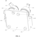
- FIG. 6 is a diagram of a structure of the water-side component 100 in FIG. 5 from another perspective.
- the water path substrate 110 includes a first surface 111 facing the heat exchanger 300, and all first functional components 120 of the water-side component 100 are distributed at other positions of the water path substrate 110 except the first surface 111.
- the first surface 111 corresponds to the heat exchanger 300, so that a size of the first surface 111 of the water path substrate 110 matches a size of the heat exchanger 300 as much as possible. This miniaturizes the water-side component 100.
- the first surface 111 is a plane. It may be understood that a curved surface with a small radian also belongs to the plane in this implementation. It may be understood that, in some other implementations, the first surface 111 may alternatively be a curved surface.
- the water path substrate 110 further includes an upper surface 112 away from the heat exchanger 300 and a side surface 113 configured to connect the first surface 111 to the upper surface 112. It may be understood that, in this implementation, words such as “upper” and “side” do not limit a direction, and are similar to words such as “first” and “second” for distinguishing names.
- the upper surface 112 is a plane
- the water path substrate 110 is a sheet-shaped plate
- all first functional components 120 are disposed on the upper surface 112.
- the upper surface 112 includes a first plane 1121, a second plane 1122, and a third plane 1123 that connects the first plane 1121 to the second plane 1122.
- the first plane 1121 and the second plane 1122 are parallel and do not overlap in the first direction Z, and the third plane 1123 is perpendicular to the first plane 1121.
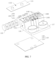
- thickness of a part corresponding to the first plane 1121 of the water path substrate 110 is less than thickness of a part corresponding to the second plane 1122 of the water path substrate 110, and the water path substrate 110 has a receptacle 1101 (as shown in FIG. 7 below). All first functional components 120 are disposed on the upper surface 112 and/or in the receptacle 1101.
- FIG. 7 is a partially exploded diagram of the water-side component 100 in FIG. 5 .
- FIG. 8a is a diagram of a partial structure of the water-side component 100 in FIG. 5 .
- FIG. 8b is a simple diagram of the water-side component 100 in FIG. 5 .
- a part of all first functional components 120 is a multi-port valve 130.
- the water path substrate 110 includes a bottom plate 114, a top plate 115, and a connection plate 116 that connects the bottom plate 114 to the top plate 115.
- the bottom plate 114 and the top plate 115 are disposed opposite to each other at an interval, a receptacle 1101 is enclosed with the bottom plate 114, the top plate 115, and the connection plate 116, and the multi-port valve 130 is disposed in the receptacle 1101 and is located between the top plate 115 and the bottom plate 114.
- a flow channel 1102 of the water path substrate 110 may be disposed around the multi-port valve 130, so that the flow channel 1102 of the water path substrate 110 is three-dimensional. This can effectively use three-dimensional space, reduce a size in a direction, and facilitate miniaturization of the water-side component 100.
- the flow channel 1102 of the water path substrate 110 is three-dimensional, to reduce design difficulty of the flow channel 1102, and further reduce bending of the flow channel 1102, thereby reducing flow resistance in the flow channel 1102.
- top plate 115 and the connection plate 116 may be integrally formed, or may be formed through splicing, and the connection plate 116 and the bottom plate 114 may be spliced, or may be integrally formed.
- the top plate 115 is parallel to the bottom plate 114. Certainly, in some other implementations, there may alternatively be a specific angle between the top plate 115 and the bottom plate 114.
- structures of the top plate 115 and the bottom plate 114 may be sheet-shaped. In some other implementations, the top plate 115 and the bottom plate 114 may be in other regular or irregular shapes.
- a shape of the water path substrate 110 is not specifically limited in this application, provided that the water path substrate 110 may form the receptacle 1101 for accommodating the multi-port valve 130.
- the multi-port valve 130 includes a plurality of water connection ports 1301, and the plurality of water connection ports 1301 are configured to communicate with different external components to form paths.
- the multi-port valve 130 in this application may be a three-port valve, a four-port valve, a five-port valve, a six-port valve, an eight-port valve, or another multi-port valve 130.
- a plurality of external connection ports 140 are disposed on the water path substrate 110.
- the water connection port 1301 first communicates with the external connection port 140, and then communicates with the external component through the external connection port 140. It may be understood that, when a position of the water connection port 1301 corresponds to a position of the external connection port 140, the water connection port 1301 may be directly communicated with the external connection port 140, the water connection port 1301 may be communicated with the external connection port 140 through the flow channel 1102 of the water path substrate 110, or some of the water connection ports 1301 may be directly communicated with the external connection ports 140, and some of the water connection ports 1301 may be communicated with the external connection ports 140 through the flow channels 1102 of the water path substrate 110.
- some of the plurality of external connection ports 140 are first external connection ports 141, and some of the plurality of external connection ports 140 are second external connection ports 142.
- the first external connection port 141 is disposed on the top plate 115, and the second external connection port 142 is disposed on the bottom plate 114.
- the plurality of first external connection ports 141 separately communicate with some of the plurality of water connection ports 1301, and the plurality of second external connection ports 142 separately communicate with some of the plurality of water connection ports 1301.
- the plurality of first external connection ports 141 are located on the top plate 115, and the plurality of second external connection ports 142 are located on the bottom plate 114.
- the multi-port valve 130 is located between the top plate 115 and the bottom plate 114, and the top plate 115 and the bottom plate 114 are in a three-dimensional architecture, to effectively reduce a size of the bottom plate 114, fully utilize three-dimensional space, and further facilitate miniaturization of the water-side component 100.
- connection port 140 may alternatively be disposed on the connection plate 116.
- the plurality of flow channels 1102 are disposed on the water path substrate 110, the plurality of flow channels 1102 are configured to communicate the plurality of first external connection ports 141 with the plurality of corresponding water connection ports 1301, and communicate the plurality of second external connection ports 142 with the plurality of corresponding water connection ports 1301.
- Some of the flow channels 1102 are configured to communicate the flow channel 1102 on the top plate 115 with the flow channel 1102 on the bottom plate 114, that is, communicating the first flow channel 1103 with the second flow channel 1104.
- the flow channel 1102 configured to communicate the first flow channel 1103 with the second flow channel 1104 is a third flow channel 1105, and there may be one or more third flow channels 1105.
- the third flow channel 1105 is configured to communicate the first flow channel 1103 on the top plate 115 with the second flow channel 1104 on the bottom plate 114, and the top plate 115 and the bottom plate 114 are disposed at an interval in the first direction Z, the first flow channel 1103, the second flow channel 1104, and the third flow channel 1105 form a 3D structure of the flow channels 1102.
- This can effectively use three-dimensional space, reduce a quantity of flow channels 1102 disposed on the bottom plate 114, reduce a size of the bottom plate 114, reduce difficulty in arranging the flow channels 1102, and facilitate a miniaturization design of the water-side component 100.
- the some of the flow channels 1102 between the top plate 115 and the bottom plate 114 are arc-shaped and extend outside a periphery of the multi-port valve 130. Because the some of the flow channels 1102 are arc-shaped and extend outside the periphery of the multi-port valve 130, the flow channels 1102 can be effectively attached to the periphery of the multi-port valve 130, to improve design compactness of the flow channels 1102, and facilitate the miniaturization design of the water-side component 100.
- the some of the flow channels 1102 that extend outside the periphery of the multi-port valve 130 and that are arc-shaped are the third flow channels 1105, and are configured to communicate the first flow channel 1103 with the second flow channel 1104.
- Some of the plurality of water connection ports 1301 are first interfaces 1302, some of the plurality of water connection ports 1301 are second interfaces 1303, the first interface 1302 is located at a position that is of the multi-port valve 130 and that faces the top plate 115, and the second interface 1303 is located at a position that is of the multi-port valve 130 and that faces the bottom plate 114.
- the first interface 1302 is located at the position that is of the multi-port valve 130 and that faces the top plate 115
- the second interface 1303 is located at the position that is of the multi-port valve 130 and that faces the bottom plate 114
- the first interface 1302 is close to the first external connection port 141 located on the top plate 115
- the second interface 1303 is close to the second external connection port 142 located on the bottom plate 114.
- This can reduce a length of the flow channel communicating the first interface 1302 with the first external connection port 141, and reduce a length of the flow channel communicating the second interface 1303 with the second external connection port 142, to effectively reduce a total length of the flow channel 1102, and further facilitate the miniaturization design of the water-side component 100.
- first interface 1302 and the second interface 1303 are located on two opposite sides in the first direction Z, some flow channels 1102 need to be located on the top plate 115, and some flow channels 1102 need to be located on the bottom plate 114, to fully utilize the three-dimensional space, so as to implement the miniaturization design.
- the multi-port valve 130 includes a valve body 131 and a valve core 132, the valve core 132 is located in an accommodation cavity 1311 of the valve body 131 and is rotatably connected to the valve body 131, and a rotation center line of the valve core 132 is an axis line a.
- the water connection port 1301 is located on the valve body 131. When the valve core 132 rotates relative to the valve body 131, the water connection port 1301 may correspond to different positions of the valve core 132, to implement conversion between different modes of the multi-port valve 130.
- a quantity of water connection ports 1301 on the valve body 131 of the multi-port valve 130 is not limited, for example, the quantity of water connection ports 1301 may be 2, 3, 4, 5, 6, 7, 8, or 9.
- a position of the water connection port 1301 is not specifically limited either.
- some water connection ports 1301 face the top plate 115, and some water connection ports 1301 face the bottom plate 114.
- the water connection ports 1301 are designed opposite to each other in the first direction Z.
- the water connection ports 1301 may alternatively be disposed adjacently on a periphery of the valve body 131.
- valve body 131 and the water path substrate 110 are integrally formed through injection molding. It may be understood that, in some implementations, the valve body 131 and the water path substrate 110 may alternatively be separately disposed.
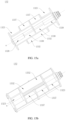
- FIG. 9 is a diagram of a structure of the valve core 132 from a perspective in the water-side component 100 in FIG. 5 .
- FIG. 10 is a diagram of a structure of the valve core 132 from another perspective in the water-side component 100 in FIG. 5 .
- FIG. 11 is a diagram of a structure of the valve core 132 from still another perspective in the water-side component 100 in FIG. 5 .
- FIG. 12 is a sectional view of A-A of the valve core 132 in FIG. 11 .
- FIG. 13 is a sectional view of B-B of the valve core 132 in FIG. 11 .
- FIG. 14 is a sectional view of the partial water-side component 100 in FIG. 8a from a perspective.
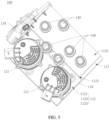
- the first interface 1302 and the second interface 1303 that communicate with each other through the vacant cavity are disposed on the valve body 131, the valve core 132 includes a first port 1321, a second port 1322, and a first channel 1323 that communicates the first port 1321 with the second port 1322, the first channel 1323 penetrates the valve core 132, a part of the axis line a is located in the first channel 1323, the first port 1321 can communicate with the first interface 1302, and the second port 1322 can communicate with the second interface 1303.
- the first channel 1323 penetrates the valve core 132 to communicate the first port 1321 with the second port 1322, the first port 1321 can communicate with the first interface 1302, and the second port 1322 can communicate with the second interface 1303. Therefore, in an implementation, the first medium entering the first interface 1302 can enter the first channel 1323 through the first port 1321, flow to the second port 1322, and then flow out of the second interface 1303, to form a path. Conversion between different modes can be implemented by opening and closing the path.
- the first channel 1323 that communicates the first port 1321 with the second port 1322 can be designed in a diversified manner, and position utilization of the valve core 132, that is, an internal region of the valve core 132, can be effectively improved. It may be understood that the internal region of the valve core 132 is relative to a peripheral region of the valve core 132. In addition, because a part of the axis line a is located in the first channel 1323, a design of the first channel 1323 does not affect a design requirement for the peripheral region of the valve core 132. When position utilization of the valve core 132 is improved and a volume of the valve core 132 is reduced, design diversity of channels in the valve core 132 can be effectively improved.
- the valve core 132 may rotate relative to the valve body 131, at a specific position during rotation, the first port 1321 communicates with the first interface 1302, and the second port 1322 communicates with the second interface 1303.
- the first port 1321 may alternatively communicate with the second interface 1303, and the second port 1322 may alternatively communicate with the first interface 1302.
- the first port 1321 and the second port 1322 may communicate with neither the first interface 1302 nor the second interface 1303. In this case, the first port 1321 and the second port 1322 are closed.
- the first interface 1302 and the second interface 1303 are distributed on two opposite sides of the axis line a. It should be noted that the two opposite sides of the axis line a mean two opposite sides of the valve core 132 (not an extension direction of the axis line a). In this implementation, the first interface 1302 and the second interface 1303 are distributed on the two opposite sides of the axis line a, the first port 1321 can communicate with the first interface 1302, and the second port 1322 can communicate with the second interface 1303. Therefore, in this implementation, the flow channel 1102 of the water path substrate 110 needs to be designed as a 3D flow channel. This can improve three-dimensional space utilization of the water path substrate 110, reduce a size in a direction, and facilitate a miniaturization design of the water-side component 100.
- the first port 1321 and the second port 1322 are disposed opposite to each other along a radial direction of the valve core 132.
- a position of the first port 1321 projected on the axis line a along the radial direction of the valve core 132 is a first position b
- a position of the first interface 1302 projected on the axis line a along the radial direction of the valve core 132 is a second position c
- the first position b and the second position c at least partially overlap, so that the first port 1321 can communicate with the first interface 1302.
- a position of the second port 1322 projected on the axis line a along the radial direction of the valve core 132 is a third position d
- a position of the second interface 1303 projected on the axis line a along the radial direction of the valve core 132 is a fourth position e
- the third position d and the fourth position e at least partially overlap, so that the second port 1322 can communicate with the second interface 1303.
- the first port 1321 directly faces the second port 1322 along the radial direction of the valve core 132.
- the first channel 1323 penetrates the valve core 132 along the radial direction of the valve core 132, and the radial direction of the valve core 132 is perpendicular to the extension direction of the axis line a. Because the first channel 1323 penetrates the valve core 132 along the radial direction of the valve core 132, the first channel 1323 is a straight-through channel from the first port 1321 to the second port 1322. This can effectively reduce flow resistance of the first medium during flowing in the first channel 1323, increase a flow velocity of the first medium, and further improve efficiency of transporting the first medium.
- the first channel 1323 may alternatively penetrate the valve core 132 along a direction inclined relative to the radial direction of the valve core 132, and the radial direction of the valve core 132 is perpendicular to the extension direction of the axis line a.
- the first medium flows in the first channel 1323. This can also reduce flow resistance, and improve transmission efficiency of the first medium.
- the first channel 1323 includes a first segment 1324 and an intermediate segment 1325 that are connected in sequence
- the first port 1321 is located at an end that is of the first segment 1324 and that is far away from the intermediate segment 1325
- a part of the axis line a is located in the intermediate segment 1325
- a diameter (a size of a cross section, perpendicular to an extension direction of the intermediate segment 1325, along the extension direction of the axis line a) of the intermediate segment 1325 is less than a diameter (a size of a section along a circumferential surface of the valve core 132, where the section is arc-shaped) of the first port 1321
- the first segment 1324 gradually extends in a direction in which the intermediate segment 1325 faces the first port 1321.
- the first segment 1324 gradually extends in the direction from the intermediate segment 1325 to the first port 1321, when the first medium entering from the first port 1321 passes through the first segment 1324, the first segment 1324 can play a guiding role, to lead the first medium into the intermediate segment 1325.
- the diameter of the intermediate segment 1325 is smaller, to accelerate a flow velocity of the first medium in the intermediate segment 1325.
- the diameter of the first port 1321 is large, so that the first segment can be easily connected to the water connection port 1301 of the valve body 131.
- the intermediate segment 1325 of the first channel 1323 is small, and the first segment 1324 gradually extends in the direction in which the intermediate segment 1325 faces the first port 1321, space is reserved for opening another groove or channel at a same layer of the valve core 132. This optimizes a size of a channel part or a groove part at the same layer, to ensure normal liquid flowing.
- the first channel 1323 further includes a second segment 1326, the first segment 1324, the intermediate segment 1325, and the second segment 1326 are connected in sequence, the second port 1322 is located at an end that is of the second segment and that is far away from the intermediate segment 1325, the diameter of the intermediate segment 1325 is less than a diameter of the second port 1322, and the second segment 1326 gradually extends in a direction in which the intermediate segment 1325 faces the second port 1322.
- the second segment 1326 can also function as the first segment 1324, and details are not described herein.
- either the first port 1321 or the second port 1322 can play guiding and acceleration roles regardless of whether the first medium enters from the first port 1321 or the second port 1322, to improve transmission efficiency of the first medium.
- the intermediate segment 1325 is a straight channel, to reduce flow resistance of the first medium in the intermediate segment 1325, and improve transport efficiency of the intermediate segment 1325.
- first segment 1324 and the second segment 1326 are sector-shaped or horn-shaped channels, and the first segment 1324 and the second segment 1326 are symmetrically disposed on two sides of the intermediate segment 1325, to improve guiding effect of the first segment 1324 and the second segment 1326 on the first medium.
- first segment 1324 and the second segment 1326 may be the same. Certainly, in some other implementations, the first segment 1324 and the second segment 1326 may be in different forms, in different sizes, in different structures, or in different sizes and shapes.
- the valve core 132 includes a first core part 1327 and a second core part 1329, the first core part 1327 and the second core part 1329 are arranged along the extension direction of the axis line a, the first port 1321, the second port 1322, and the first channel 1323 are located in the first core part 1327, a third port 1335, a fourth port 1336, and a second channel 1337 that communicates the third port 1335 with the fourth port 1336 are disposed on the second core part 1329, the second channel 1337 penetrates the valve core 132, a part of the axis line a is located in the second channel 1337, a third interface 1304 and a fourth interface 1305 are disposed at positions that are of the valve body 131 and that correspond to the second core part 1329, the third interface 1304 and the fourth interface 1305 are distributed on two opposite sides of the axis line a, the third interface 1304 can communicate with the third port 1335, and the fourth interface
- the second channel 1337 penetrates the valve core 132 to communicate the third port 1335 with the fourth port 1336, the third port 1335 can communicate with the third interface 1304, and the fourth port 1336 can communicate with the fourth interface 1305. Therefore, in an implementation, the first medium entering the third interface 1304 can enter the second channel 1337 through the third port 1335, flow to the fourth port 1336, and then flow out of the fourth interface 1305, to form a path. Conversion between different modes can be implemented by opening and closing the path.
- the second channel 1337 penetrates the valve core 132
- the second channel 1337 that communicates the third port 1335 with the fourth port 1336 can be designed in a diversified manner, and position utilization of the valve core 132 can be effectively improved, that is, the internal region of the valve core 132 is effectively used.
- a design of the second channel 1337 does not affect a design requirement for the peripheral region of the valve core 132.
- the second channel 1337 penetrates the valve core 132 along the radial direction of the valve core 132.
- the second channel 1337 may alternatively penetrate the valve core 132 along the direction inclined relative to the radial direction of the valve core 132. For specific effect, refer to the first channel 1323.
- the second channel 1337 and the first channel 1323 have a similar structure: a diameter of an intermediate part is less than diameters of parts at two ends, to improve guiding effect and transmission efficiency.
- a diameter of an intermediate part is less than diameters of parts at two ends, to improve guiding effect and transmission efficiency.
- a size of the first port 1321 is greater than a size of the third port 1335, and a size of the second port 1322 is greater than a size of the fourth port 1336, so that in a status in which the first channel 1323 communicates the first interface 1302 with the second interface 1303, the second core part 1329 has a first status and a second status, the second channel 1337 communicates the third interface 1304 with the fourth interface 1305 in the first status, and the second channel 1337 does not communicate the third interface 1304 with the fourth interface 1305 in the second status.
- the valve core 132 in this implementation can generate at least two modes.
- the second core part 1329 is in the first status
- the first port 1321 communicates with the first interface 1302
- the second port 1322 communicates with the second interface 1303
- the third port 1335 communicates with the third interface 1304
- the fourth port 1336 communicates with the fourth interface 1305.
- the first port 1321 communicates with the second port 1322
- the third port 1335 communicates with the fourth port 1336, to form two independent flow channels to be communicated with an external flow channel 1102 or component.
- the central angles corresponding to the first port 1321 and the second port 1322 are the first angle f
- the central angles corresponding to the third port 1335 and the fourth port 1336 are the second angle g
- the first angle f is 1.5 to 2.5 times the second angle g.
- sizes of the first interface 1302, the second interface 1303, the third interface 1304, and the fourth interface 1305 each are less than or equal to sizes of the third port 1335 and the fourth port 1336. Therefore, the first port 1321, the second port 1322, the third port 1335, and the fourth port 1336 can be completely communicated with the first interface 1302 and the second interface 1303. In other words, the first interface 1302, the second interface 1303, the third interface 1304, and the fourth interface 1305 all can completely fall within regions corresponding to the first port 1321, the second port 1322, the third port 1335, and the fourth port 1336.
- the first interface 1302, the second interface 1303, the third interface 1304, and the fourth interface 1305 have a same shape and size.
- the first interface 1302 is used as an example.
- a port that is of the first interface 1302 and that faces the valve core 132 is arc-shaped, a central angle corresponding to the port that is of the first interface 1302 and that faces the valve core 132 is a third angle h, and the third angle h is less than or equal to the second angle g.
- the third angle h is 60 degrees. It may be understood that the third angle h being 60 degrees means that the third angle h is approximately 60 degrees, for example, may be 50 to 70 degrees.
- the first core part 1327 is further provided with a first groove 1328. It may be understood that a quantity of first grooves 1328 may be set based on a requirement. The quantity of first grooves 1328 is not limited in this application.
- the first interface 1302, the second interface 1303, and the first groove 1328 are located at a same layer in the extension direction of the axis line a of the valve core 132. Therefore, when the valve core 132 rotates, the first groove 1328 can communicate with the first interface 1302. When the valve core 132 rotates to another position, the first groove 1328 may also communicate with the second interface 1303. When the valve core 132 rotates to another position, the first groove 1328 may communicate with neither the first interface 1302 nor the second interface 1303.
- the second core part 1329 is further provided with a second groove 1330. It may be understood that a quantity of second grooves 1330 may be set based on a requirement. The quantity of second grooves 1330 is not limited in this application.
- the third interface 1304, the fourth interface 1305, and the second groove 1330 are located at a same layer in the extension direction of the axis line a of the valve core 132. Therefore, when the valve core 132 rotates, the second groove 1330 may communicate with the third interface 1304. When the valve core 132 rotates to another position, the second groove 1330 may also communicate with the fourth interface 1305. When the valve core 132 rotates to another position, the second groove 1330 may communicate with neither the third interface 1304 nor the fourth interface 1305.
- the first groove 1328 and the second groove 1330 at least partially face each other in the extension direction of the axis line a, and the valve core 132 is provided with a first through hole 1331 configured to communicate the first groove 1328 with the second groove 1330.
- the first groove 1328 and the second groove 1330 at least partially face each other in the extension direction of the axis line a, and the first through hole 1331 communicates the first groove 1328 with the second groove 1330, so that the first groove 1328 of the first core part 1327 communicates with the second groove 1330 of the second core part 1329, to form one flow channel 1102.
- the first medium may enter the first groove 1328 from the first interface 1302, enter the second groove 1330 through the first through hole 1331, and then flow out of the second groove 1330, and vice versa.
- a first partition plate 1338 is disposed between the first groove 1328 and the second groove 1330, and the first partition plate 1338 is provided with the first through hole 1331.
- the first partition plate 1338 is disposed between the first groove 1328 and the second groove 1330, to effectively improve structure strength of the valve core 132, and increase a service life.
- a shape of the first through hole 1331 in this implementation is not specifically limited, for example, the first through hole 1331 may be a circular through hole, a rectangular through hole, or a through hole of another shape.
- a size of the first through hole 1331 in this implementation is not specifically limited either. The size of the through hole may be adjusted during manufacturing based on a specific design requirement. For example, when the size of the first through hole 1331 is large enough, the first groove 1328 can completely communicate with the second groove 1330, and no first partition plate 1338 is disposed.
- thickness of the first partition plate 1338 is not limited either.
- the first through hole 1331 extends along the extension direction of the axis line a, to communicate the first groove 1328 with the second groove 1330 in the extension direction of the axis line a.
- the first through hole 1331 is a straight through hole.
- each second core part 1329 has a plurality of second grooves 1330, and the plurality of second grooves 1330 on the two second core parts 1329 are in a one-to-one correspondence in the extension direction of the axis line a.
- the two second core parts 1329 are provided with third grooves 1332, the third grooves 1332 of the two second core parts 1329 directly face the first channel 1323 in the extension direction of the axis line a, the valve core 132 is provided with a second through hole 1333, and the second through hole 1333 is configured to communicate the two third grooves 1332 with each other.
- the two third grooves 1332 directly face the first channel 1323 in the extension direction of the axis line a
- the first channel 1323 directly faces the second channel 1337 in the extension direction of the axis line a.
- the first interface 1302 communicates with the first port 1321
- the second interface 1303 communicates with the second port 1322
- the third interface 1304 communicates with the third groove 1332
- the fourth interface 1305 communicates with the third groove 1332.
- the first interface 1302 communicates with the first port 1321
- the second interface 1303 communicates with the second port 1322
- the third interface 1304 communicates with the third port 1335
- the fourth interface 1305 communicates with the fourth port 1336.
- the second through hole 1333 extends along the extension direction of the axis line a, to communicate the third grooves 1332 of the two second core parts 1329 with each other in the extension direction of the axis line a.
- the second through hole 1333 is a straight through hole.
- a second partition plate 1339 is disposed between adjacent third grooves 1332, and the second partition plate 1339 is provided with the second through hole 1333.
- the second partition plate 1339 is disposed between the third grooves 1332, to effectively improve structure strength of the valve core 132, and increase a service life.
- a shape of the second through hole 1333 in this implementation is not specifically limited, for example, the second through hole 1333 may be a circular through hole, a rectangular through hole, or a through hole of another shape.
- a size of the second through hole 1333 in this implementation is not specifically limited either. The size of the through hole may be adjusted during manufacturing based on a specific design requirement. For example, when the size of the second through hole 1333 is large enough, the adjacent third grooves 1332 can completely communicate with each other, and no second partition plate 1339 is disposed.
- thickness of the second partition plate 1339 is not limited either.
- a port of the first groove 1328 and the third port 1335 are in a same size and shape.
- a port of the second groove 1330 and the third port 1335 are in a same size and shape.
- a port of the third groove 1332 and the third port 1335 are in a same size and shape.
- sizes of the first groove 1328, the second groove 1330, and the third groove 1332 may be set based on an actual requirement, or may be different from a size and a shape of the third port 1335.
- the first core part 1327 and the second core part 1329 form one core structure unit 1334
- the valve core 132 includes at least two core structure units 1334
- the at least two core structure units 1334 are arranged in a stacked manner along the extension direction of the axis line a.
- first core parts 1327 may be 2, 3, 4, 5, or another quantity
- second core parts 1329 may be 2, 3, 4, 5, or another quantity
- the valve core 132 includes a multi-layer core structure, the multi-layer core structure is distributed in a stacked manner along the extension direction of the axis line a, and the first port 1321, the first channel 1323, and the second port 1322 are distributed at one layer of the core structure.
- FIG. 15a is a simple diagram of a structure of another multi-port valve 130 according to this application.
- FIG. 15b is a diagram of a structure of the multi-port valve 130 in FIG. 15a from another perspective.
- the first partition plate 1338 in FIG. 10 is not disposed between the first groove 1328 and the second groove 1330, to directly communicate the first groove 1328 with the second groove 1330.
- a side wall of the first groove 1328 parallel to the extension direction of the axis line a and a side wall of the second groove 1330 parallel to the extension direction of the axis line a are located in a same plane, to effectively reduce flow resistance of the first medium when the first medium flows between the first groove 1328 and the second groove 1330, and increase a flow velocity.
- extension directions of the first groove 1328, the second groove 1330, the first partition plate 1338, and the axis line a that are provided in an embodiment, refer to the foregoing embodiments. Details are not described herein again.
- the second partition plate 1339 in FIG. 10 is not disposed between the adjacent third grooves 1332, to directly communicate the adjacent third grooves 1332 with each other.
- the adjacent third grooves 1332 that are parallel to the extension direction of the axis line a are located in a same plane, to effectively reduce flow resistance of the first medium when the first medium flows between the adjacent third grooves 1332, and increase a flow velocity.
- the third groove 1332 and the second partition plate 1339 that are increased in an embodiment refer to the foregoing embodiments. Details are not described herein again.
- FIG. 16a to FIG. 16e are simple diagrams of structures of other multi-port valves 130 according to this application.
- a proportionally adjustable port 1312 is disposed on the valve body 131, in a circumferential direction of the valve core 132, the proportionally adjustable port 1312 is adjacent to the first interface 1302 and/or the second interface 1303, the proportionally adjustable port 1312 can communicate with the first port 1321 or the second port 1322, and the proportionally adjustable port 1312, and the first interface 1302 and/or the second interface 1303 can communicate with the corresponding first port 1321 and/or the corresponding second port 1322.
- the proportionally adjustable port 1312 when the valve core 132 rotates, the proportionally adjustable port 1312 rotates relative to the first port 1321, so that a size of an overlapping part between the proportionally adjustable port 1312 and the first port 1321 changes. Therefore, the proportionally adjustable port 1312 is used to adjust a proportion of the first medium that enters or flows out of the first port 1321.
- the proportionally adjustable port 1312 when one proportionally adjustable port 1312 and one first interface 1302 can communicate with the second port 1322, the proportionally adjustable port 1312 may be used to adjust a proportion of the first medium that enters or flows out of the second port 1322.
- the proportionally adjustable port 1312 is adjacent to the first interface 1302 and/or the second interface 1303, the proportionally adjustable port 1312, the first interface 1302, and the second interface 1303 can communicate with the first port 1321 or the second port 1322, to implement proportional adjustment of flows of the first port 1321 and the second port 1322.
- the proportionally adjustable port 1312 being adjacent to the first interface 1302 and/or the second interface 1303 means that on a radial section i of the valve core 132, a projection of the proportionally adjustable port 1312 is adjacent to a projection of the first interface 1302 and/or a projection of the second interface 1303 on the radial section i of the valve core 132. This is also applicable to the following embodiments. Details are not described in the following.
- the proportionally adjustable port 1312 is adjacent to the first interface 1302.
- the valve core 132 rotates to a specific position
- a part of the first port 1321 directly faces the proportionally adjustable port 1312
- a part of the first port 1321 directly faces the first interface 1302.
- the valve core 132 rotates to a position that completely staggers the proportionally adjustable port 1312 from the first port 1321, it is equivalent to that the proportionally adjustable port 1312 is closed.
- the proportionally adjustable port 1312 is adjacent to the third interface 1304 and/or the fourth interface 1305, and the proportionally adjustable port 1312 can communicate with the third port 1335 or the fourth port 1336.
- the proportionally adjustable port 1312 is adjacent to the third interface 1304.
- the valve core 132 rotates to a specific position, a part of the third port 1335 directly faces the proportionally adjustable port 1312, and a part of the third port 1335 directly faces the third interface 1304.
- the valve core 132 rotates to a position that completely staggers the proportionally adjustable port 1312 from the third port 1335, it is equivalent to that the proportionally adjustable port 1312 is closed.
- a core structure is used as an example.
- the core structure includes one first core part 1327 and one second core part 1329.
- the first interface 1302, the second interface 1303, the third interface 1304, and the fourth interface 1305 are disposed on the corresponding valve body 131.
- the proportionally adjustable port 1312 may be disposed in at least the following plurality of manners, some of the manners are shown in FIG. 16a to FIG. 16e , and some of the manners are not shown in the accompanying drawings.
- one proportionally adjustable port 1312 is disposed at a position, on the valve body 131, corresponding to the first core part 1327, and the proportionally adjustable port 1312 is adjacent to the first interface 1302.
- one proportionally adjustable port 1312 is disposed at a position, on the valve body 131, corresponding to the first core part 1327, and the proportionally adjustable port 1312 is adjacent to the second interface 1303.
- one proportionally adjustable port 1312 is disposed at a position, on the valve body 131, corresponding to the second core part 1329, and the proportionally adjustable port 1312 is adjacent to the third interface 1304.
- one proportionally adjustable port 1312 is disposed at a position, on the valve body 131, corresponding to the second core part 1329, and the proportionally adjustable port 1312 is adjacent to the fourth interface 1305.
- two proportionally adjustable ports 1312 are disposed at positions, on the valve body 131, corresponding to the first core part 1327, and the two proportionally adjustable ports 1312 are adjacent to two sides of the first interface 1302.
- two proportionally adjustable ports 1312 are disposed at positions, on the valve body 131, corresponding to the first core part 1327, and the two proportionally adjustable ports 1312 are adjacent to two sides of the second interface 1303.
- two proportionally adjustable ports 1312 are disposed at positions, on the valve body 131, corresponding to the second core part 1329, and the two proportionally adjustable ports 1312 are adjacent to two sides of the third interface 1304.
- two proportionally adjustable ports 1312 are disposed at positions, on the valve body 131, corresponding to the second core part 1329, and the two proportionally adjustable ports 1312 are adjacent to two sides of the fourth interface 1305.
- two proportionally adjustable ports 1312 are disposed at positions, on the valve body 131, corresponding to the first core part 1327, one proportionally adjustable port 1312 is adjacent to the first interface 1302, and one proportionally adjustable port 1312 is adjacent to the second interface 1303.
- two proportionally adjustable ports 1312 are disposed on the valve body 131, one proportionally adjustable port 1312 is adjacent to the first interface 1302, and one proportionally adjustable port 1312 is adjacent to the third interface 1304.
- two proportionally adjustable ports 1312 are disposed on the valve body 131, one proportionally adjustable port 1312 is adjacent to the first interface 1302, and one proportionally adjustable port 1312 is adjacent to the fourth interface 1305.
- two proportionally adjustable ports 1312 are disposed on the valve body 131, one proportionally adjustable port 1312 is adjacent to the second interface 1303, and one proportionally adjustable port 1312 is adjacent to the third interface 1304.
- two proportionally adjustable ports 1312 are disposed on the valve body 131, one proportionally adjustable port 1312 is adjacent to the second interface 1303, and one proportionally adjustable port 1312 is adjacent to the fourth interface 1305.
- two proportionally adjustable ports 1312 are disposed at positions, on the valve body 131, corresponding to the second core part 1329, one proportionally adjustable port 1312 is adjacent to the third interface 1304, and one proportionally adjustable port 1312 is adjacent to the fourth interface 1305.
- three proportionally adjustable ports 1312 are disposed on the valve body 131, one proportionally adjustable port 1312 is adjacent to the first interface 1302, one proportionally adjustable port 1312 is adjacent to the second interface 1303, and one proportionally adjustable port 1312 is adjacent to the third interface 1304.
- three proportionally adjustable ports 1312 are disposed on the valve body 131, one proportionally adjustable port 1312 is adjacent to the first interface 1302, one proportionally adjustable port 1312 is adjacent to the second interface 1303, and one proportionally adjustable port 1312 is adjacent to the fourth interface 1305.
- three proportionally adjustable ports 1312 are disposed on the valve body 131, one proportionally adjustable port 1312 is adjacent to the second interface 1303, one proportionally adjustable port 1312 is adjacent to the third interface 1304, and one proportionally adjustable port 1312 is adjacent to the fourth interface 1305.
- proportionally adjustable ports 1312 are disposed on the valve body 131, one proportionally adjustable port 1312 is adjacent to the first interface 1302, one proportionally adjustable port 1312 is adjacent to the second interface 1303, one proportionally adjustable port 1312 is adjacent to the third interface 1304, and one proportionally adjustable port 1312 is adjacent to the fourth interface 1305.
- two or more proportionally adjustable ports 1312 may alternatively be disposed adjacent to one first interface 1302.
- the multi-port valve 130 further includes an actuator 134, and the actuator 134 is configured to drive the valve core 132 to rotate relative to the valve body 131.
- the valve core 132 includes a plurality of core parts that are sequentially arranged along the extension direction of the axis line a, and the first port 1321, the second port 1322, and the first channel 1323 are disposed on one of the core parts.
- a plurality of core parts are integrally formed.
- the plurality of core parts may be driven by using one actuator 134.
- At least one core part can rotate relative to another core part.
- at least two actuators 134 are required to separately drive the core parts to rotate.
- the connection plate 116 includes a first board 117. In the first direction Z, the first board 117 is located between the top plate 115 and the bottom plate 114.
- first functional components 120 are water pumps 121, and some of the remaining first functional components 120 are multi-port valves 130. It may be understood that, in some other implementations, the first functional component 120 may further include another component, for example, may further integrate with a temperature sensor, a water level switch, the water tank 12, a controller of the water pump 121, a valve of the water pump 121, a pulser, or an overflow valve.
- the water pump 121 is distributed on the first plane 1121, and at least a part of the multi-port valve 130 is disposed at a position that is in the receptacle 1101 and that corresponds to the second plane 1122. Because at least a part of the multi-port valve 130 is located inside the water path substrate 110, the flow channel 1102 of the water path substrate 110 may be designed in a 3D architecture. This can effectively use three-dimensional space, reduce a size that is of the water path substrate 110 and that is in a direction perpendicular to the first direction Z, and facilitate miniaturization of the water-side component 100.
- the first surface 111 is a surface that is of the bottom plate 114 and that faces the heat exchanger 300
- the second plane 1122 is a surface that is of the top plate 115 and that is away from the heat exchanger 300. It may be understood that in some other implementations, the surface that is of the top plate 115 and that is away from the heat exchanger 300 may be not a plane, but may be a curved surface.
- FIG. 17 is a diagram of a working principle of the thermal management system 1 according to an embodiment of this application.
- FIG. 18 shows a connection status of each water connection port 1301 when the multi-port valve 130 is in three different modes.
- the valve core 132 includes two core structure units 1334.
- the two core structure units 1334 are symmetrically disposed, that is, two second core parts 1329 are disposed in a stacked manner along the extension direction of the axis line a, and two first core parts 1327 are respectively located on two opposite sides of the two second core parts 1329 in the extension direction of the axis line a.
- the two first core parts 1327 have a same structure.
- the first core part 1327 is provided with two first grooves 1328, a first port 1321 and a second port 1322 that are opposite to each other along the valve core 132 in a radial direction, and a first channel 1323 that communicates the first port 1321 with the second port 1322.
- the two second core parts 1329 have a same structure.
- the second core part 1329 is provided with two second grooves 1330, two third grooves 1332, a third port 1335 and a fourth port 1336 that are opposite to each other along the valve core 132 in a radial direction, and a second channel 1337 that communicates the third port 1335 with the fourth port 1336.
- the first groove 1328, the second groove 1330, the third groove 1332, the third port 1335, and the fourth port 1336 all correspond to a same central angle, and the central angles corresponding to the first port 1321 and the second port 1322 are twice the central angle corresponding to the third port 1335.
- the central angles corresponding to the first groove 1328, the second groove 1330, the third groove 1332, the third port 1335, and the fourth port 1336 are all 60 degrees, and central angles corresponding to the first port 1321 and the second port 1322 are 120 degrees.
- the first groove 1328 and second groove 1330 that are adjacent are opposite to each other and communicate with each other through the first through hole 1331
- two adjacent third grooves 1332 are opposite to each other and communicate with each other through the second through hole 1333
- a part of the first channel 1323 directly faces the adjacent second channel 1337
- a part of the first channel 1323 directly faces the adjacent third groove 1332.
- Two water connection ports 1301 are disposed on the valve body 131.
- Two water connection ports 1301 are first inlets 1302, two water connection ports 1301 are second inlets 1303, two water connection ports 1301 are third interfaces 1304, two water connection ports 1301 are fourth interfaces 1305, and one water connection port 1301 is a proportionally adjustable port 1312.
- a pair of a first interface 1302 and a second interface 1303 that directly face each other in the radial direction of the valve body 131 are disposed at positions that are of the valve body 131 and that correspond to each of the two first core parts 1327 and each of the two second core parts 1329, and the proportionally adjustable port 1312 is located at one layer of the core parts.
- the thermal management system 1 includes an evaporator, an evaporation plate heat exchanger, a condenser, a condensation plate heat exchanger, the compressor 14, the gas-liquid separator 13, a check valve, an expansion valve, a solenoid valve, the multi-port valve 130, the water pump 121, and a radiator.
- the thermal management object 2 adjusted by the thermal management system 1 is a heat source 1 and a heat source 2.
- the heat source 1 is a powertrain
- the heat source 2 is a battery.
- the multi-port valve 130 is an eight-port valve, and nine water connection ports 1301 of the valve body 131 are respectively an interface 1, an interface 2, an interface 3, an interface 4, an interface 6, an interface 7, an interface 8, an interface 5, and an interface 9.
- the interface 9 is a proportionally adjustable port 1312. Two ends of the evaporation plate heat exchanger are separately connected to the interface 3 and the interface 8, and the first medium flowing out of the interface 3 flows into the interface 8 through the water pump 1 and the evaporation plate heat exchanger. Two ends of the heat source 2 are separately connected to the interface 1 and the interface 6, and the first medium flowing out of the interface 6 flows into the interface 1 through the heat source 2.
- Two ends of the radiator are separately connected to the interface 7 and the interface 4, and the first medium flowing out of the interface 7 flows into the interface 4 through the radiator.
- One end of the heat source 1 is connected to the interface 2, and the other end of the heat source 1 is separately connected to the interface 9 and the interface 5. After passing through the water pump 2 and the heat source 1, the first medium that flows out of the interface 2 may directly flow into the interface 9, or may flow into the interface 5 through the condensation plate heat exchanger.
- the multi-port valve 130 has three modes.
- a mode 1 the interface 1 communicates with the interface 3, the interface 2 communicates with the interface 4, the interface 9 communicates with the interface 7, the interface 5 communicates with the interface 7, and the interface 6 communicates with the interface 8.
- the interface 1 communicates with the interface 2
- the interface 3 communicates with the interface 9
- the interface 3 communicates with the interface 5
- the interface 4 communicates with the interface 6,
- the interface 7 communicates with the interface 8.
- the interface 1 communicates with the interface 2
- the interface 3 communicates with the interface 4
- the interface 9 communicates with the interface 6
- the interface 5 communicates with the interface 6, and the interface 7 communicates with the interface 8.
- the actuator 134 drives the valve core 132 to rotate relative to the valve body 131, to implement conversion between the three modes.
- a first flow channel may be formed: interface 3 ⁇ interface 8 ⁇ interface 6 ⁇ interface 1 ⁇ interface 3. Because the first medium flowing out of the interface 3 flows into the interface 8 through the water pump 1 and the evaporation plate heat exchanger, and the evaporation plate heat exchanger performs evaporation for cooling, the first medium in the first flow channel may have a low temperature, to cool the heat source 2.
- the heat source 2 is a battery, a powertrain, an electronic control module, or the like
- the thermal management system 1 in the mode 1 may be used for heat dissipation of the battery, the powertrain, and the electronic control module in summer. When cold air generated by the evaporation plate heat exchanger blows to the interior vehicle, it can also cool the interior vehicle.
- a second flow channel may further be formed: interface 7 ⁇ interface 4 ⁇ interface 2 ⁇ interface 9 (5) ⁇ interface 7.
- heat dissipation may be performed on the heat source 1 by using the radiator.
- the first medium heated by the condensation plate heat exchanger connected to the interface 5 does not flow to the interface 7.
- heat dissipation may be performed on the heat source 1 by using the radiator, to cool the heat source 1.
- Different heat sources may be set as the heat source 1 based on a requirement.
- the heat source 1 may alternatively be a battery, a powertrain, or an electronic control module.
- the second flow channel may also be used for cooling in summer. When the interface 5 is opened, more widely the interface 5 is opened, more first media that are heated by the condensation plate heat exchanger flow to the second flow channel, and heating effect is better. In this case, the heat source 1 may be heated.
- first flow channel and the second flow channel may be opened and closed independently. In summer, both the first flow channel and the second flow channel may be opened, and the interface 9 is completely closed, to dissipate heat from the heat source 1 and the heat source 2. In winter, the first flow channel may be closed, the second flow channel may be opened, and the interface 9 may be opened.
- the heat source 1 is heated by using the condenser, for example, the battery is heated in winter.
- a third flow channel may be formed: interface 2 ⁇ interface 9 (5) ⁇ interface 3 ⁇ interface 8 ⁇ interface 7 ⁇ interface 4 ⁇ interface 6 ⁇ interface 1 ⁇ interface 2.
- the first medium cooled by the evaporation plate heat exchanger may flow to the third flow channel passing through the heat source 1, the heat source 2, and the radiator respectively, to perform heat dissipation on the heat source 1 and the heat source 2 for cooling.
- the thermal management system 1 in the mode 2 may be used in winter.
- the first medium that is heated by the condensation plate heat exchanger may flow to the third flow channel passing through the heat source 1, the heat source 2, and the radiator respectively, to heat the heat source 1 and the heat source 2 and adjust temperatures of the heat source 1 and the heat source 2.
- a fourth flow channel may be formed: interface 2 ⁇ interface 9 (5) ⁇ interface 6 ⁇ interface 1 ⁇ interface 2.
- the first medium that is heated by the condenser may flow to the fourth flow channel, to heat the heat source 1 and the heat source 2.
- the thermal management system 1 in the mode 3 may be used in winter.
- the interface 5 is closed, heat balance of the heat source 1 and heat balance of the heat source 2 may be implemented.
- a fifth flow channel may further be formed: interface 3 ⁇ interface 8 ⁇ interface 7 ⁇ interface 4 ⁇ interface 3.
- the interior vehicle may be heat up through the fifth flow channel.
Landscapes
- Engineering & Computer Science (AREA)
- General Engineering & Computer Science (AREA)
- Mechanical Engineering (AREA)
- Physics & Mathematics (AREA)
- Thermal Sciences (AREA)
- Chemical & Material Sciences (AREA)
- Combustion & Propulsion (AREA)
- Transportation (AREA)
- Multiple-Way Valves (AREA)
Abstract
Description
- This application relates to the field of thermal management technologies, and in particular, to a multi-port valve, a water-side component, a thermal management integrated system, and a vehicle.
- A multi-port valve in a related technology includes a valve body and a valve core. An outer circumferential surface of the valve core is provided with several grooves, and water connection ports for communicating with the grooves are disposed on the valve body. When the valve core is rotated, and two water connection ports are correspondingly communicated with a same groove, a path may be formed through the groove and the two water connection ports, which causes a small circumferential interval between the two water connection ports. Consequently, a fluid needs to pass through a small curve when flowing in the path, and flow resistance of the fluid is large, which is not conducive to transport efficiency of the fluid.
- Embodiments of this application provide a multi-port valve, a water-side component, a thermal management integrated system, and a vehicle, to reduce flow resistance of the multi-port valve.
- According to a first aspect, an embodiment of this application provides a multi-port valve, including a valve body and a valve core. The valve core is located in an accommodation cavity of the valve body and is rotatably connected to the valve body, a rotation center line of the valve core is an axis line, a first interface and a second interface that communicate with each other through the vacant cavity are disposed on the valve body, the first interface and the second interface are distributed on two opposite sides of the axis line, the valve core includes a first port, a second port, and a first channel that communicates the first port with the second port, the first channel penetrates the valve core, a part of the axis line is located in the first channel, the first port can communicate with the first interface, and the second port can communicate with the second interface. In this embodiment, when the valve core is rotated, the first port can communicate with the first interface, and the second port can communicate with the second interface, to form a path. The first interface and the second interface are distributed on the two opposite sides of the axis line, to increase an interval between the first interface and the second interface in an axial direction of the valve body, so as to prevent a first medium (for example, water) flowing in the valve core from flowing through a sharp curve at a small angle. Therefore, this can effectively reduce flow resistance, and improve transmission efficiency. In addition, because the first channel penetrates the valve core, and a part of the axis line is located in the first channel, a length of the first channel can be effectively reduced. This can save a limited volume of the valve core, and effectively reduce flow resistance.
- In an embodiment, the first channel penetrates the valve core along a radial direction of the valve core, and the radial direction of the valve core is perpendicular to an extension direction of the axis line. Because the first channel penetrates the valve core along the radial direction of the valve core, the first channel is a straight-through channel from the first port to the second port. This can effectively reduce flow resistance of the first medium during flowing in the first channel, increase a flow velocity of the first medium, and further improve efficiency of transporting the first medium.
- In some embodiments, the first channel may alternatively penetrate the valve core along a direction inclined relative to a radial direction of the valve core, and the radial direction of the valve core is perpendicular to an extension direction of the axis line. In this implementation, the first medium flows in the first channel. This can also reduce flow resistance, and improve transmission efficiency of the first medium.
- In an embodiment, the first channel includes a first segment and an intermediate segment that are connected in sequence, the first port is located at an end that is of the first segment and that is far away from the intermediate segment, a part of the axis line is located in the intermediate segment, a diameter of the intermediate segment is less than a diameter of the first port, and the first segment gradually extends in a direction in which the intermediate segment faces the first port. Because the first segment gradually extends in the direction from the intermediate segment to the first port, when the first medium entering from the first port passes through the first segment, the first segment can play a guiding role, to lead the first medium into the intermediate segment. In addition, the diameter of the intermediate segment is smaller, to accelerate a flow velocity of the first medium in the intermediate segment. The diameter of the first port is large, so that the first segment can be easily connected to a water connection port of the valve body. In addition, because a size of the intermediate segment of the first channel is small, and the first segment gradually extends in the direction in which the intermediate segment faces the first port, space is reserved for opening another groove or channel at a same layer of the valve core. This optimizes a size of a channel part or a groove part at the same layer, to ensure normal liquid flowing.
- In an embodiment, the first channel further includes a second segment, the first segment, the intermediate segment, and the second segment are connected in sequence, the second port is located at an end that is of the second segment and that is far away from the intermediate segment, the diameter of the intermediate segment is less than a diameter of the second port, and the second segment gradually extends in a direction in which the intermediate segment faces the second port. In this embodiment, space can also be reserved for opening another groove or channel at a same layer of the valve core. This optimizes a size of a channel part or a groove at the same layer, to ensure normal liquid flowing.
- In an embodiment, the valve core includes a first core part and a second core part, the first core part and the second core part are arranged along the extension direction of the axis line, the first port, the second port, and the first channel are located in the first core part, a third port, a fourth port, and a second channel that communicates the third port with the fourth port are disposed on the second core part, the second channel penetrates the valve core, a part of the axis line is located in the second channel, a third interface and a fourth interface are disposed at positions that are of the valve body and that correspond to the second core part, the third interface and the fourth interface are distributed on the two opposite sides of the axis line, the third interface can communicate with the third port, and the fourth interface can communicate with the fourth port.
- A size of the first port is greater than a size of the third port, so that in a status in which the first channel communicates the first interface with the second interface, the second core part has a first status and a second status, the second channel communicates the third interface with the fourth interface in the first status, and the second channel does not communicate the third interface with the fourth interface in the second status. Because the size of the first port is greater than the size of the third port, and a size of the second port is greater than a size of the fourth port, the valve core in this implementation can generate at least two modes. In one mode, the second core part is in the first status, the first port communicates with the first interface, the second port communicates with the second interface, the third port communicates with the third interface, and the fourth port communicates with the fourth interface. The first port communicates with the second port, and the third port communicates with the fourth port, to form two independent flow channels to be communicated with an external flow channel or component. In another mode, the second core part is in the second status, the first port communicates with the first interface, the second port communicates with the second interface, the third port does not communicate with the third interface, and the fourth port does not communicate with the fourth interface. In this case, only one flow channel is connected. In addition, there is another mode. In this mode, the first port does not communicate with the first interface, the second port does not communicate with the second interface, the third port does not communicate with the third interface, and the fourth port does not communicate with the fourth interface. The multi-port valve in this implementation has different modes, so that the multi-port valve can implement multi-way control.
- In an embodiment, the valve core includes a plurality of layers of core parts, and the first core part and the second core part are core parts at two adjacent layers. Different modes may be generated through cooperation between the first core part and the second core part.
- In an embodiment, the first core part and the second core part form one core structure unit, the valve core includes at least two core structure units, and the at least two core structure units are arranged in a stacked manner along the extension direction of the axis line. More use modes can be generated through cooperation between a plurality of core structures.
- In an embodiment, sizes of the first interface, the second interface, the third interface, and the fourth interface each are less than or equal to the size of the third port. Therefore, the first port, the second port, the third port, and the fourth port can all be completely communicated with the first interface and the second interface. In other words, the first interface, the second interface, the third interface, and the fourth interface all can completely fall within regions corresponding to the first port, the second port, the third port, and the fourth port.
- In an embodiment, the first core part is provided with a first groove, the second core part is provided with a second groove, the first groove can communicate with the first interface or the second interface, the second groove can communicate with the third interface or the fourth interface, the first groove and the second groove at least partially face each other in the extension direction of the axis line, and the valve core is provided with a first through hole configured to communicate the first groove with the second groove. The first groove cooperates with the second groove, to generate a new communication manner, so as to generate a new mode to adapt to different requirements.
- In an embodiment, the first through hole extends along the extension direction of the axis line, to communicate the first groove with the second groove in the extension direction of the axis line. Because the first through hole extends along the extension direction of the axis line, the first through hole is a straight through hole. When the first medium flows from the first groove to the second groove, or flows from the second groove to the first groove, flow resistance of the first medium passing through the first through hole is reduced, to improve transmission efficiency of the first medium in the first through hole.
- In an embodiment, there are two second core parts, the two second core parts are stacked and adjacent along the extension direction of the axis line, each second core part has a plurality of second grooves, and the plurality of second grooves on the two second core parts are in a one-to-one correspondence in the extension direction of the axis line. Because the plurality of second grooves on the two second core parts are in a one-to-one correspondence in the extension direction of the axis line, processing difficulty can be reduced during processing, and an overall structure of the valve core can be regular, thereby improving a force balance of the valve core.
- In an embodiment, there are two second core parts, the two second core parts are provided with third grooves, the two third grooves face the first channel in the extension direction of the axis line, the valve core is provided with a second through hole, and the second through hole is configured to communicate the two third grooves with each other. The second through hole is configured to communicate the two third grooves with each other, to generate a new communication manner, so as to generate a new mode to adapt to different requirements.
- In an embodiment, a proportionally adjustable port is disposed on the valve body, in a circumferential direction of the valve core, the proportionally adjustable port is adjacent to the first interface and/or the second interface, the proportionally adjustable port can communicate with the first port or the second port, and the proportionally adjustable port, and the first interface and/or the second interface can communicate with the corresponding first port and/or the corresponding second port. In this embodiment, because the proportionally adjustable port is adjacent to the first interface and/or the second interface, the proportionally adjustable port, the first interface, and the second interface can communicate with the first port or the second port, to implement proportional adjustment of flows of the first port and the second port.
- In an embodiment, the valve core includes a plurality of core parts that are sequentially arranged along the extension direction of the axis line, the first port, the second port, and the first channel are disposed on one of the core parts, and at least one of the core parts can rotate relative to another core part. Because at least one of the core parts can rotate relative to another core part, the valve core in this embodiment can generate more use modes for usage in a solution that requires a plurality of paths.
- According to a second aspect, an embodiment of this application provides a water-side component. The water-side component includes a water path substrate and a multi-port valve, the water path substrate includes a bottom plate, a top plate, and a connection plate that connects the bottom plate to the top plate, and the bottom plate and the top plate are disposed opposite to each other at an interval. A receptacle is enclosed with the bottom plate, the top plate, and the connection plate, the multi-port valve is disposed in the receptacle and is located between the top plate and the bottom plate, and the multi-port valve includes a plurality of water connection ports. A plurality of first external connection ports are disposed on the top plate, a plurality of second external connection ports are disposed on the bottom plate, the plurality of first external connection ports are separately communicated with some of the plurality of water connection ports, and the plurality of second external connection ports are separately communicated with some of the plurality of water connection ports. Because the multi-port valve is located in the receptacle, a flow channel of the water path substrate may be disposed around the multi-port valve, so that the flow channel of the water path substrate is three-dimensional. This can effectively use three-dimensional space, reduce a size in a direction, and facilitate miniaturization of the water-side component. In addition, the flow channel of the water path substrate is three-dimensional, to reduce design difficulty of the flow channel, and further reduce bending of the flow channel, thereby reducing flow resistance in the flow channel.
- In an embodiment, a plurality of flow channels are disposed on the water path substrate, the plurality of flow channels are configured to communicate the plurality of first external connection ports with the plurality of corresponding water connection ports, and communicate the plurality of second external connection ports with the plurality of corresponding water connection ports, some of the flow channels are formed on the top plate, some of the flow channels are formed on the bottom plate, and some of the flow channels are configured to communicate the flow channel on the top plate with the flow channel on the bottom plate. Because some flow channels are located on the top plate, some flow channels are located on the bottom plate, and some flow channels are configured to communicate the flow channels on the top plate with the flow channels on the bottom plate, a 3D structure of flow channels is formed. This can effectively use three-dimensional space, reduce a quantity of flow channels disposed on the bottom plate, reduce a size of the bottom plate, reduce difficulty in arranging the flow channels, and facilitate a miniaturization design of the water-side component.
- In an embodiment, the some of the flow channels between the top plate and the bottom plate are arc-shaped and extend outside a periphery of the multi-port valve. Because the some of the flow channels are arc-shaped and extend outside the periphery of the multi-port valve, the flow channels can be effectively attached to the periphery of the multi-port valve, to improve design compactness of the flow channels, and facilitate the miniaturization design of the water-side component.
- In an embodiment, some of the plurality of water connection ports are first interfaces, some of the plurality of water connection ports are second interfaces, the first interface is located at a position that is of the multi-port valve and that faces the top plate, and the second interface is located at a position that is of the multi-port valve and that faces the bottom plate. Because the first interface is located at the position that is of the multi-port valve and that faces the top plate, and the second interface is located at the position that is of the multi-port valve and that faces the bottom plate, the first interface is close to the first external connection port located on the top plate, and the second interface is close to the second external connection port located on the bottom plate. This can reduce a length of the flow channel communicating the first interface with the first external connection port, and reduce a length of the flow channel communicating the second interface with the second external connection port, to effectively reduce a total length of the flow channel, and further facilitate the miniaturization design of the water-side component. In addition, because the first interface and the second interface are located on two opposite sides in a first direction, some flow channels need to be located on the top plate, and some flow channels need to be located on the bottom plate, to fully utilize the three-dimensional space, so as to implement the miniaturization design.
- In an embodiment, the multi-port valve includes a valve body and a valve core, the valve core is located in an accommodation cavity of the valve body and is rotatably connected to the valve body, and a rotation center line of the valve core is an axis line. The first interface and the second interface that communicate with each other through the vacant cavity are disposed on the valve body, and the first interface and the second interface are distributed on two opposite sides of the axis line. The valve core includes a first port, a second port, and a first channel that communicates the first port with the second port, the first channel penetrates the valve core, a part of the axis line is located in the first channel, the first port can communicate with the first interface, and the second port can communicate with the second interface.
- In an embodiment, the connection plate includes a first plate, the first plate is located between the top plate and the bottom plate in the first direction, the first direction is a direction in which the top plate and the bottom plate are arranged, the water-side component further includes a water pump, the water pump is disposed on a side that is of the first plate and that is away from the bottom plate, and an outlet and an inlet of the water pump directly communicate with the flow channel. Because the water pump is disposed on the side that is of the first plate and that is away from the bottom plate, and the first plate is located between the top plate and the bottom plate in the first direction, the three-dimensional space can be effectively used, to effectively improve miniaturization of the water-side component.
- According to a third aspect, an embodiment of this application provides a thermal management module, including a refrigerant component, a heat exchanger, and the water-side component in the first aspect. A first medium flowing in the water-side component and a second medium flowing in the refrigerant component perform heat exchange by using the heat exchanger.
- According to a fourth aspect, an embodiment of this application provides a thermal management system, including a refrigerant component, a heat exchanger, the water-side component in the first aspect. A first medium flowing in the water-side component and a second medium flowing in the refrigerant component perform heat exchange by using the heat exchanger.
- According to a fifth aspect, an embodiment of this application provides a thermal management system, including a water tank, a gas-liquid separator, and the thermal management integrated module in the third aspect. The thermal management integrated module is connected to the water tank and the gas-liquid separator through a coolant hose.
- According to a sixth aspect, an embodiment of this application provides a vehicle, including a battery, a powertrain, and the thermal management integrated system in the fifth aspect. The thermal management integrated system is configured to perform thermal management on the battery and the powertrain.
- According to a seventh aspect, this application provides an energy storage system, including an energy storage battery and the thermal management system in the fifth aspect. The thermal management system is configured to perform thermal management on the energy storage battery.
- To describe technical solutions in embodiments of the present invention or in the conventional technology more clearly, the following briefly describes the accompanying drawings for describing embodiments or the conventional technology.
-
FIG. 1a is a diagram of a structure of a vehicle according to an embodiment of this application; -
FIG. 1b is an operating block diagram of a thermal management system of a vehicle according to an embodiment of this application; -
FIG. 2 is an operating block diagram of a thermal management system of an energy storage system according to an embodiment of this application; -
FIG. 3 is a diagram of a structure of a thermal management integrated module according to an embodiment of this application; -
FIG. 4 is an exploded diagram of the thermal management integrated module inFIG. 3 ; -
FIG. 5 is a diagram of a structure of a water-side component in the thermal management integrated module inFIG. 3 ; -
FIG. 6 is a diagram of a structure of the water-side component inFIG. 5 from another perspective; -
FIG. 7 is a partially exploded diagram of the water-side component inFIG. 5 ; -
FIG. 8a is a diagram of a partial structure of the water-side component inFIG. 5 ; -
FIG. 8b is a simple diagram of the water-side component inFIG. 5 ; -
FIG. 9 is a diagram of a structure of a valve core from a perspective in the water-side component inFIG. 5 ; -
FIG. 10 is a diagram of a structure of a valve core from another perspective in the water-side component inFIG. 5 ; -
FIG. 11 is a diagram of a structure of a valve core from still another perspective in the water-side component inFIG. 5 ; -
FIG. 12 is a sectional view of A-A of the valve core inFIG. 11 ; -
FIG. 13 is a sectional view of B-B of the valve core inFIG. 11 ; -
FIG. 14 is a sectional view of the partial water-side component inFIG. 8a from a perspective; -
FIG. 15a is a simple diagram of a structure of a multi-port valve 130 according to this application; -
FIG. 15b is a diagram of a structure of the multi-port valve 130 inFIG. 15a from another perspective; -
FIG. 16a to FIG. 16e are diagrams of structures of other multi-port valves according to this application; -
FIG. 17 is a diagram of a working principle of a thermal management system according to an embodiment of this application; and -
FIG. 18 shows a connection status of each water connection port when a multi-port valve is in three different modes. - Z: first direction; a: axis line; b: first position; c: second position; d: third position; e: fourth position; f: first angle; g: second angle; h: third angle; i: radial section of a valve core; 1000: vehicle; 2000: energy storage system; 1: thermal management system; 11: thermal management integrated module; 12: water tank; 13: gas-liquid separator; 14: compressor; 2: thermal management object; 100: water-side component; 110: water path substrate; 1101: receptacle; 1102: flow channel; 1103: first flow channel; 1104: second flow channel; 1105: third flow channel; 111: first surface; 112: upper surface; 1121: first plane; 1122: second plane; 1123: third plane; 113: side surface; 114: bottom plate; 115: top plate; 116: connection plate; 117: first board; 120: first functional component; 121: water pump; 130: multi-port valve; 1301: water connection port; 1302: first interface; 1303: second interface; 1304: third interface; 1305: fourth interface; 131: valve body; 1311: accommodation cavity; 1312: proportionally adjustable port; 132: valve core; 1321: first port; 1322: second port; 1323: first channel; 1324: first segment; 1325: intermediate segment; 1326: second segment; 1327: first core part; 1328: first groove; 1329: second core part; 1330: second groove; 1331: first through hole; 1332: third groove; 1333: second through hole; 1334: core structure unit; 1335: third port; 1336: fourth port; 1337: second channel; 1338: first partition plate; 1339: second partition plate; 134: actuator; 140: external connection port; 141: first external connection port; 142: second external connection port; 143: water path port; 200: refrigerant component; 210: refrigerant substrate; 220: second functional component; 230: refrigerant port; 300: heat exchanger; 310: water path connection port; 320: refrigerant connection port; and 400: fastening structure.
- The following first explains some terms in embodiments of this application.
- In the specification, claims, and accompanying drawings of embodiments of this application, terms "first", "second", "third", "fourth", and the like are intended to distinguish between similar objects but do not necessarily indicate a specific order or sequence. It should be understood that the data termed in such a way are interchangeable in proper circumstances so that embodiments of this application described herein can be implemented in orders except the order illustrated or described herein. In addition, terms "include", "contain", and any other variants mean to cover the non-exclusive inclusion, for example, a process, method, system, product, or device that includes a list of steps or units is not necessarily limited to those steps or units, but may include other steps or units not expressly listed or inherent to such a process, method, product, or device.
- In this specification, terms such as "perpendicularity" and "parallelism" are explained.
- Perpendicularity: Perpendicularity defined in this application is not limited to an absolute perpendicular intersection (an included angle is 90 degrees) relationship, a non-absolute perpendicular intersection relationship caused by factors such as an assembly tolerance, a design tolerance, and a structural flatness is allowed, and an error within a small angle range is allowed. For example, a relationship within an assembly angle range of 80 degrees to 100 degrees may be understood as the perpendicular relationship.
- Parallelism: Parallelism defined in this application is not limited to absolute parallelism. The definition of parallelism may be understood as basic parallelism, and non-absolute parallelism caused by factors such as an assembly tolerance, a design tolerance, and a structure flatness is allowed. The factors may cause a case in which a sliding cooperation part and a first door plate are not absolutely parallel, but this application also defines, as parallelism, the case in which the sliding cooperation part and the first door plate are not absolutely parallel.
- It should be noted that the accompanying drawings in the following are diagrams, and specific shapes in the accompanying drawings are not specific shapes protected in this application.
- An embodiment of this application provides a thermal management system. The thermal management system in embodiments of this application is applicable to the vehicle-mounted field and the energy storage field.
- For example, the thermal management system in embodiments of this application may be used in an electric vehicle in the vehicle-mounted field, and the electric vehicle is transport driven by an electric power module. The electric power module may include, for example, a power distribution unit (PDU), a microcontroller unit (MCU), mapped diagnostic context (MDC), and a motor.
- For another example, the thermal management system in embodiments of this application may be used in a photovoltaic system and a wind power system in the energy storage field.
-
FIG. 1a is a diagram of a structure of avehicle 1000 according to an embodiment of this application.FIG. 1b is an operating block diagram of athermal management system 1 of thevehicle 1000 according to an embodiment of this application. - Refer to
FIG. 1a and FIG. 1b . An embodiment of this application further provides thevehicle 1000. Thevehicle 1000 includes thethermal management system 1 and athermal management object 2. Thethermal management system 1 is configured to perform thermal management on thethermal management object 2. It may be understood that positions of thethermal management object 2 and thethermal management system 1 in the figure are merely examples, and do not indicate that thethermal management object 2 and thethermal management system 1 need to be located in the positions shown in the figure. Thethermal management object 2 and thethermal management system 1 may alternatively be disposed at other positions. - In some implementations, the
thermal management object 2 includes one or more of a battery, a powertrain, and an electronic control module. For the electric vehicle, the battery is configured to provide most of electric energy required by thevehicle 1000. The powertrain is configured to provide power for thevehicle 1000, and the powertrain may include a motor, a transmission, a drive system, and an exhaust system. The electronic control module is an overall system including elements such as an electronic control unit (ECU), a harness, and a sensor that are of the vehicle, and the electronic control module may perform refined adjustment, control, and management on an automotive engine, the transmission, braking, and security control, to ensure smooth driving and stability of the vehicle in various complex driving scenarios. The electronic control module of the vehicle is an important part of the vehicle, and has high requirements on matching, debugging, maintenance, upgrading, and the like of an electronic device. - The
thermal management system 1 is configured to monitor and control a temperature of thevehicle 1000, and maintain a normal operating temperature range of each part (for example, the battery, the powertrain, the electronic control module, and an interior of the vehicle) of thevehicle 1000, to improve performance, efficiency, and comfort of thevehicle 1000. - The
thermal management system 1 includes a thermal management integratedmodule 11, awater tank 12, and a gas-liquid separator 13. - The
water tank 12 is configured to provide circulated water for the thermal management integratedmodule 11. Because thewater tank 12 is independent of the thermal management integratedmodule 11 and is connected to the thermal management integratedmodule 11 through a coolant hose, a position of thewater tank 12 may be decoupled from a position of the thermal management integratedmodule 11. For example, thewater tank 12 is placed at a higher position, and the thermal management integratedmodule 11 is placed at a lower position than thewater tank 12. This can improve use performance of thewater tank 12 and the thermal management integratedmodule 11, and further enable the thermal management integratedmodule 11 in this embodiment to be adapted to different environments, for example, the thermal management integratedmodule 11 may be used in thevehicle 1000 and the energy storage system. In addition, thewater tank 12 and the thermal management integratedmodule 11 are separately and independently disposed. Therefore, the thermal management integratedmodule 11 is not affected by thewater tank 12 with a large volume, to facilitate miniaturization of the thermal management integratedmodule 11. - Similarly, a component with a large volume like the gas-
liquid separator 13 may also be independent of the thermal management integratedmodule 11, and is connected to the thermal management integratedmodule 11 through a coolant hose, to facilitate miniaturization of the thermal management integratedmodule 11. - In some implementations, a
compressor 14 in thethermal management system 1 may also be disposed independently of the thermal management integratedmodule 11. Certainly, in some implementations, thecompressor 14 may alternatively be integrated into the thermal management integratedmodule 11. -
FIG. 2 is an operating block diagram of athermal management system 1 of anenergy storage system 2000 according to an embodiment of this application. - Refer to
FIG. 2 . Theenergy storage system 2000 includes thethermal management system 1 and thethermal management object 2, and thethermal management system 1 includes a thermal management integratedmodule 11, awater tank 12, and a gas-liquid separator 13. For the thermal management integratedmodule 11, thewater tank 12, and the gas-liquid separator 13, refer to the foregoing embodiment inFIG. 1b . Details are not described herein again. Thethermal management object 2 in this embodiment is an energy storage battery, a power control system (PCS), a DC-DC converter, and the like. -
FIG. 3 is a diagram of a structure of the thermal management integratedmodule 11 according to an embodiment of this application.FIG. 4 is an exploded diagram of the thermal management integratedmodule 11 inFIG. 3 . The thermal management integratedmodule 11 in this embodiment may be used in thethermal management system 1 in embodiments inFIG. 1b andFIG. 2 , or maybe used in anotherthermal management system 1, for example, athermal management system 1 in the electronic and medical fields. - Refer to
FIG. 3 andFIG. 4 . The thermal management integratedmodule 11 includes a water-side component 100, a refrigerant component 200, and aheat exchanger 300. - The water-
side component 100 in this embodiment is mainly configured to adjust and control flowing of a first medium in the system, to ensure normal operation of the device and temperature control. For example, the first medium in the water-side component 100 may flow to positions such as the battery, the powertrain, and a control unit, to implement temperature control and adjustment on the battery, the powertrain, the control unit, and the like. - The refrigerant component 200 in this embodiment is mainly configured to control a refrigerant to circulate in the system, and implement temperature adjustment through heat absorption and heat release.
- A main function of the
heat exchanger 300 in this embodiment is to implement heat exchange. For example, in some implementations, theheat exchanger 300 may be a condenser. In some implementations, theheat exchanger 300 may alternatively be an evaporator. In some implementations, theheat exchanger 300 may alternatively include both a condenser and an evaporator. - The water-
side component 100 and the refrigerant component 200 are separately connected to theheat exchanger 300, so that heat exchange between the first medium (for example, water) flowing from the water-side component 100 to theheat exchanger 300 and a second medium (for example, a refrigerant) flowing from the refrigerant component 200 to theheat exchanger 300 is implemented by using theheat exchanger 300. - The water-
side component 100 and the refrigerant component 200 are respectively located on two opposite sides of theheat exchanger 300, so that the water-side component 100, the refrigerant component 200, and theheat exchanger 300 are disposed in a "sandwich" architecture. In comparison with a solution in which aheat exchanger 300 is integrated on a side that is of a refrigerant component 200 and that is away from a water-side component 100, in this application, a size of the refrigerant component 200 can be reduced, and connection stability of functional components on the refrigerant component 200 can further be improved. - In some embodiments, the water-
side component 100 includes awater path substrate 110 and several functional components located on thewater path substrate 110. For ease of description, the functional components in the water-side component 100 are a firstfunctional component 120. The refrigerant component 200 includes arefrigerant substrate 210 and several functional components located on therefrigerant substrate 210. For ease of description, the functional components in the refrigerant component 200 are a secondfunctional component 220. Theheat exchanger 300 is located in gap space between thewater path substrate 110 and therefrigerant substrate 210, to form a "sandwich" architecture. This can facilitate miniaturization of therefrigerant substrate 210, save a material of therefrigerant substrate 210, and improve strength of therefrigerant substrate 210. - In some implementations, the
water path substrate 110 directly faces therefrigerant substrate 210 in a first direction Z. The first direction Z is also a direction in which the water-side component 100, theheat exchanger 300, and the refrigerant component 200 are sequentially arranged. In comparison with a solution in which theheat exchanger 300 is fastened on the side that is of therefrigerant substrate 210 and that is away from thewater path substrate 110, in embodiments of this application, therefrigerant substrate 210 does not need to be provided with a through hole for placing theheat exchanger 300, to save a base material for manufacturing therefrigerant substrate 210, and reduce costs. In addition, because therefrigerant substrate 210 is not provided with a through hole for placing theheat exchanger 300, strength of therefrigerant substrate 210 is enhanced, and a volume of therefrigerant substrate 210 is reduced. Miniaturization of the volume of therefrigerant substrate 210 can also improve strength of therefrigerant substrate 210. - In some implementations, a
water path port 143 is disposed on a side that is of thewater path substrate 110 and that faces theheat exchanger 300, a waterpath connection port 310 is disposed on a side that is of theheat exchanger 300 and that faces thewater path substrate 110, and thewater path substrate 110 is connected to the waterpath connection port 310 of theheat exchanger 300 through thewater path port 143. Thewater path port 143 is located on the side that is of thewater path substrate 110 and that faces theheat exchanger 300, and the waterpath connection port 310 is located on the side that is of theheat exchanger 300 and that faces thewater path substrate 110, to conveniently connect thewater path substrate 110 to the waterpath connection port 310. In addition, a length of a coolant hose that connects thewater path substrate 110 to theheat exchanger 300 may be reduced, to facilitate miniaturization of the thermal management integratedmodule 11. - In some implementations, the
water path port 143 is directly communicated with the waterpath connection port 310, and thewater path substrate 110 communicates with theheat exchanger 300 through the waterpath connection port 310 and thewater path port 143, or thewater path substrate 110 may be fastened to theheat exchanger 300 through the waterpath connection port 310 and thewater path port 143. - In some implementations, the
water path port 143 is communicated with the waterpath connection port 310 through a flexible coolant hose (not shown in the figure). Because thewater path port 143 is communicated with the waterpath connection port 310 through the flexible coolant hose, when thewater path substrate 110 deforms, hard contact does not occur on thewater path port 143 and the waterpath connection port 310, and thewater path port 143 and the waterpath connection port 310 are not damaged, to avoid a leakage from thewater path port 143 and the waterpath connection port 310. - In some implementations, the
water path port 143 and the waterpath connection port 310 may also be made of flexible materials. Thewater path port 143 communicates with a flow channel of thewater path substrate 110, and the waterpath connection port 310 communicates with a flow channel of theheat exchanger 300. Certainly, in some other implementations, thewater path port 143 and the waterpath connection port 310 may also be made of rigid materials. - In some implementations, the
water path port 143 and thewater path substrate 110 are integrally disposed. In some implementations, thewater path port 143 and thewater path substrate 110 are spliced. - In some implementations, the water
path connection port 310 and a housing of theheat exchanger 300 are integrated. In some implementations, the waterpath connection port 310 and theheat exchanger 300 are spliced. - In some implementations, the
refrigerant port 230 is disposed on a side that is of therefrigerant substrate 210 and that faces theheat exchanger 300, arefrigerant connection port 320 is disposed on a side that is of theheat exchanger 300 and that faces therefrigerant substrate 210, and therefrigerant substrate 210 is connected to therefrigerant connection port 320 of theheat exchanger 300 through therefrigerant port 230. Therefrigerant port 230 is located on the side that is of therefrigerant substrate 210 and that faces theheat exchanger 300, and therefrigerant connection port 320 is located on the side that is of theheat exchanger 300 and that faces therefrigerant substrate 210, to conveniently connect therefrigerant substrate 210 to therefrigerant connection port 320. In addition, a length of a coolant hose that connects therefrigerant substrate 210 to theheat exchanger 300 may be reduced, to facilitate miniaturization of the thermal management integratedmodule 11. - In some implementations, the
refrigerant port 230 is directly communicated with therefrigerant connection port 320, and therefrigerant substrate 210 communicates with theheat exchanger 300 through therefrigerant connection port 320 and therefrigerant port 230, or therefrigerant substrate 210 may be fastened to theheat exchanger 300 through therefrigerant connection port 320 and therefrigerant port 230. - In some implementations, the
refrigerant port 230 is communicated with therefrigerant connection port 320 through a flexible coolant hose. Because therefrigerant port 230 is communicated with therefrigerant connection port 320 through a flexible coolant hose, when therefrigerant substrate 210 deforms, hard contact does not occur on therefrigerant port 230 and therefrigerant connection port 320, and therefrigerant port 230 and therefrigerant connection port 320 are not damaged, to avoid a leakage from therefrigerant port 230 and therefrigerant connection port 320. - It may be understood that, in an embodiment of this application, the water-
side component 100 and theheat exchanger 300 may be detachable, and may be connected through a flexible coolant hose after being detached. The water-side component 100 and theheat exchanger 300 may be connected through a flexible coolant hose after being detached. A detachable connection structure between the water-side component 100 and theheat exchanger 300 enables the thermal management integratedmodule 11 provided in embodiments of this application to more flexibly match different use scenarios. - In some implementations, the
refrigerant port 230 and therefrigerant substrate 210 are integrally disposed. In some implementations, therefrigerant port 230 and therefrigerant substrate 210 are spliced. - In some implementations, the
refrigerant connection port 320 and the housing of theheat exchanger 300 are integrated. In some implementations, therefrigerant connection port 320 and theheat exchanger 300 are spliced. - In some implementations, at least part of the
heat exchanger 300 is in contact with thewater path substrate 110, and at least part of theheat exchanger 300 is in contact with therefrigerant substrate 210. Because two sides that are of the heat exchanger and that are in the first direction Z are in contact with both thewater path substrate 110 and therefrigerant substrate 210, it can be ensured that a distance between thewater path substrate 110 and therefrigerant substrate 210 is short, and gap space between thewater path substrate 110 and therefrigerant substrate 210 is only used to accommodate theheat exchanger 300. This helps implement a small size of the entire thermal management integratedmodule 11. - It may be understood that, in some implementations, the
heat exchanger 300 is at least partially in contact with therefrigerant substrate 210, or theheat exchanger 300 is at least partially in contact with thewater path substrate 110. - It may be understood that, in an embodiment of this application, the refrigerant component 200 and the
heat exchanger 300 may be detachable, and may be connected through a flexible coolant hose after being detached. A detachable connection structure between the refrigerant component 200 and theheat exchanger 300 enables the thermal management integratedmodule 11 provided in embodiments of this application to more flexibly match different use scenarios. - In some implementations, the
water path substrate 110 and/or therefrigerant substrate 210 include/includes afastening structure 400, and thefastening structure 400 is configured to fasten the thermal management integratedmodule 11 in a use environment. Thewater path substrate 110 and/or therefrigerant substrate 210 may be fastened, by using thefastening structure 400, in a use environment that needs to be fastened, so that the thermal management integratedmodule 11 in embodiments is fastened in the use environment that needs to be fastened. - In some implementations, the
fastening structure 400 is a fastening through hole with which thewater path substrate 110 and/or therefrigerant substrate 210 are/is provided. - In some implementations, a side face of the
water path substrate 110 and/or a side face of therefrigerant substrate 210 is provided with the fastening through hole, and the side face of thewater path substrate 110 and/or the side face of therefrigerant substrate 210 is a face adjacent to a face facing theheat exchanger 300, so that integration of the functional component and theheat exchanger 300 is not affected. - It may be understood that, in some other implementations, the
water path substrate 110 and/or therefrigerant substrate 210 may alternatively be fastened, by using theheat exchanger 300, at a position that needs to be fastened. -
FIG. 5 is a diagram of a structure of the water-side component 100 in the thermal management integratedmodule 11 inFIG. 3 .FIG. 6 is a diagram of a structure of the water-side component 100 inFIG. 5 from another perspective. - Refer to
FIG. 5 andFIG. 6 . In some embodiments, thewater path substrate 110 includes afirst surface 111 facing theheat exchanger 300, and all firstfunctional components 120 of the water-side component 100 are distributed at other positions of thewater path substrate 110 except thefirst surface 111. Thefirst surface 111 corresponds to theheat exchanger 300, so that a size of thefirst surface 111 of thewater path substrate 110 matches a size of theheat exchanger 300 as much as possible. This miniaturizes the water-side component 100. - In some implementations, the
first surface 111 is a plane. It may be understood that a curved surface with a small radian also belongs to the plane in this implementation. It may be understood that, in some other implementations, thefirst surface 111 may alternatively be a curved surface. - In some implementations, the
water path substrate 110 further includes anupper surface 112 away from theheat exchanger 300 and aside surface 113 configured to connect thefirst surface 111 to theupper surface 112. It may be understood that, in this implementation, words such as "upper" and "side" do not limit a direction, and are similar to words such as "first" and "second" for distinguishing names. - In some implementations, the
upper surface 112 is a plane, thewater path substrate 110 is a sheet-shaped plate, and all firstfunctional components 120 are disposed on theupper surface 112. - In some implementations, the
upper surface 112 includes afirst plane 1121, asecond plane 1122, and athird plane 1123 that connects thefirst plane 1121 to thesecond plane 1122. Thefirst plane 1121 and thesecond plane 1122 are parallel and do not overlap in the first direction Z, and thethird plane 1123 is perpendicular to thefirst plane 1121. In this implementation, thickness of a part corresponding to thefirst plane 1121 of thewater path substrate 110 is less than thickness of a part corresponding to thesecond plane 1122 of thewater path substrate 110, and thewater path substrate 110 has a receptacle 1101 (as shown inFIG. 7 below). All firstfunctional components 120 are disposed on theupper surface 112 and/or in thereceptacle 1101. -
FIG. 7 is a partially exploded diagram of the water-side component 100 inFIG. 5 .FIG. 8a is a diagram of a partial structure of the water-side component 100 inFIG. 5 .FIG. 8b is a simple diagram of the water-side component 100 inFIG. 5 . - Refer to
FIG. 5 to FIG. 7 . A part of all firstfunctional components 120 is a multi-port valve 130. Thewater path substrate 110 includes abottom plate 114, atop plate 115, and aconnection plate 116 that connects thebottom plate 114 to thetop plate 115. Thebottom plate 114 and thetop plate 115 are disposed opposite to each other at an interval, areceptacle 1101 is enclosed with thebottom plate 114, thetop plate 115, and theconnection plate 116, and the multi-port valve 130 is disposed in thereceptacle 1101 and is located between thetop plate 115 and thebottom plate 114. Because the multi-port valve 130 is located in thereceptacle 1101, aflow channel 1102 of thewater path substrate 110 may be disposed around the multi-port valve 130, so that theflow channel 1102 of thewater path substrate 110 is three-dimensional. This can effectively use three-dimensional space, reduce a size in a direction, and facilitate miniaturization of the water-side component 100. In addition, theflow channel 1102 of thewater path substrate 110 is three-dimensional, to reduce design difficulty of theflow channel 1102, and further reduce bending of theflow channel 1102, thereby reducing flow resistance in theflow channel 1102. - It may be understood that the
top plate 115 and theconnection plate 116 may be integrally formed, or may be formed through splicing, and theconnection plate 116 and thebottom plate 114 may be spliced, or may be integrally formed. - In some implementations, the
top plate 115 is parallel to thebottom plate 114. Certainly, in some other implementations, there may alternatively be a specific angle between thetop plate 115 and thebottom plate 114. - It may be understood that, in some implementations, structures of the
top plate 115 and thebottom plate 114 may be sheet-shaped. In some other implementations, thetop plate 115 and thebottom plate 114 may be in other regular or irregular shapes. - It may be understood that a shape of the
water path substrate 110 is not specifically limited in this application, provided that thewater path substrate 110 may form thereceptacle 1101 for accommodating the multi-port valve 130. - In some implementations, the multi-port valve 130 includes a plurality of
water connection ports 1301, and the plurality ofwater connection ports 1301 are configured to communicate with different external components to form paths. - It may be understood that the multi-port valve 130 in this application may be a three-port valve, a four-port valve, a five-port valve, a six-port valve, an eight-port valve, or another multi-port valve 130.
- Specifically, a plurality of
external connection ports 140 are disposed on thewater path substrate 110. Thewater connection port 1301 first communicates with theexternal connection port 140, and then communicates with the external component through theexternal connection port 140. It may be understood that, when a position of thewater connection port 1301 corresponds to a position of theexternal connection port 140, thewater connection port 1301 may be directly communicated with theexternal connection port 140, thewater connection port 1301 may be communicated with theexternal connection port 140 through theflow channel 1102 of thewater path substrate 110, or some of thewater connection ports 1301 may be directly communicated with theexternal connection ports 140, and some of thewater connection ports 1301 may be communicated with theexternal connection ports 140 through theflow channels 1102 of thewater path substrate 110. - In some implementations, some of the plurality of
external connection ports 140 are firstexternal connection ports 141, and some of the plurality ofexternal connection ports 140 are secondexternal connection ports 142. The firstexternal connection port 141 is disposed on thetop plate 115, and the secondexternal connection port 142 is disposed on thebottom plate 114. The plurality of firstexternal connection ports 141 separately communicate with some of the plurality ofwater connection ports 1301, and the plurality of secondexternal connection ports 142 separately communicate with some of the plurality ofwater connection ports 1301. In this implementation, the plurality of firstexternal connection ports 141 are located on thetop plate 115, and the plurality of secondexternal connection ports 142 are located on thebottom plate 114. In comparison with that allexternal connection ports 140 are disposed on thebottom plate 114, because some of the firstexternal connection ports 141 are located on thetop plate 115, a quantity ofexternal connection ports 140 disposed on thebottom plate 114 can be effectively reduced. The multi-port valve 130 is located between thetop plate 115 and thebottom plate 114, and thetop plate 115 and thebottom plate 114 are in a three-dimensional architecture, to effectively reduce a size of thebottom plate 114, fully utilize three-dimensional space, and further facilitate miniaturization of the water-side component 100. - It may be understood that, in some implementations, the
external connection port 140 may alternatively be disposed on theconnection plate 116. - In some implementations, the plurality of second
external connection ports 142 are located on a side that is of thebottom plate 114 and that faces theheat exchanger 300, that is, disposed on thefirst surface 111. In this implementation, the secondexternal connection port 142 is thewater path port 143, and is configured to connect to the waterpath connection port 310 of theheat exchanger 300. - Refer to
FIG. 7 ,FIG. 8a, and FIG. 8b . In some embodiments, the plurality offlow channels 1102 are disposed on thewater path substrate 110, the plurality offlow channels 1102 are configured to communicate the plurality of firstexternal connection ports 141 with the plurality of correspondingwater connection ports 1301, and communicate the plurality of secondexternal connection ports 142 with the plurality of correspondingwater connection ports 1301. - Some of the
flow channels 1102 are formed on thetop plate 115. For ease of description, theflow channel 1102 formed on thetop plate 115 is afirst flow channel 1103. There may be one or morefirst flow channels 1103, some of thefirst flow channels 1103 are configured to connect to the firstexternal connection ports 141, and some of thefirst flow channels 1103 are configured to connect to the secondexternal connection ports 142. - Some of the
flow channels 1102 are formed on thebottom plate 114. For ease of description, theflow channel 1102 formed on thebottom plate 114 is asecond flow channel 1104. There may be one or moresecond flow channels 1104, some of thesecond flow channels 1104 are configured to connect to the firstexternal connection ports 141, and some of thesecond flow channels 1104 are configured to connect to the secondexternal connection ports 142. - Some of the
flow channels 1102 are configured to communicate theflow channel 1102 on thetop plate 115 with theflow channel 1102 on thebottom plate 114, that is, communicating thefirst flow channel 1103 with thesecond flow channel 1104. Theflow channel 1102 configured to communicate thefirst flow channel 1103 with thesecond flow channel 1104 is athird flow channel 1105, and there may be one or morethird flow channels 1105. - In this implementation, because the
first flow channel 1103 is located on thetop plate 115, thesecond flow channel 1104 is located on thebottom plate 114, thethird flow channel 1105 is configured to communicate thefirst flow channel 1103 on thetop plate 115 with thesecond flow channel 1104 on thebottom plate 114, and thetop plate 115 and thebottom plate 114 are disposed at an interval in the first direction Z, thefirst flow channel 1103, thesecond flow channel 1104, and thethird flow channel 1105 form a 3D structure of theflow channels 1102. This can effectively use three-dimensional space, reduce a quantity offlow channels 1102 disposed on thebottom plate 114, reduce a size of thebottom plate 114, reduce difficulty in arranging theflow channels 1102, and facilitate a miniaturization design of the water-side component 100. - In some implementations, some of the
flow channels 1102 may alternatively be formed on theconnection plate 116. For example, some of thethird flow channels 1105 may be disposed on theconnection plate 116, to fully utilize an effective use area of theconnection plate 116. - In some implementations, the some of the
flow channels 1102 between thetop plate 115 and thebottom plate 114 are arc-shaped and extend outside a periphery of the multi-port valve 130. Because the some of theflow channels 1102 are arc-shaped and extend outside the periphery of the multi-port valve 130, theflow channels 1102 can be effectively attached to the periphery of the multi-port valve 130, to improve design compactness of theflow channels 1102, and facilitate the miniaturization design of the water-side component 100. - In some implementations, the some of the
flow channels 1102 that extend outside the periphery of the multi-port valve 130 and that are arc-shaped are thethird flow channels 1105, and are configured to communicate thefirst flow channel 1103 with thesecond flow channel 1104. - Refer to
FIG. 5 to FIG. 8b . Some of the plurality ofwater connection ports 1301 arefirst interfaces 1302, some of the plurality ofwater connection ports 1301 aresecond interfaces 1303, thefirst interface 1302 is located at a position that is of the multi-port valve 130 and that faces thetop plate 115, and thesecond interface 1303 is located at a position that is of the multi-port valve 130 and that faces thebottom plate 114. In this implementation, because thefirst interface 1302 is located at the position that is of the multi-port valve 130 and that faces thetop plate 115, and thesecond interface 1303 is located at the position that is of the multi-port valve 130 and that faces thebottom plate 114, thefirst interface 1302 is close to the firstexternal connection port 141 located on thetop plate 115, and thesecond interface 1303 is close to the secondexternal connection port 142 located on thebottom plate 114. This can reduce a length of the flow channel communicating thefirst interface 1302 with the firstexternal connection port 141, and reduce a length of the flow channel communicating thesecond interface 1303 with the secondexternal connection port 142, to effectively reduce a total length of theflow channel 1102, and further facilitate the miniaturization design of the water-side component 100. In addition, because thefirst interface 1302 and thesecond interface 1303 are located on two opposite sides in the first direction Z, someflow channels 1102 need to be located on thetop plate 115, and someflow channels 1102 need to be located on thebottom plate 114, to fully utilize the three-dimensional space, so as to implement the miniaturization design. - Refer to
FIG. 7 andFIG. 8b . The multi-port valve 130 includes avalve body 131 and avalve core 132, thevalve core 132 is located in anaccommodation cavity 1311 of thevalve body 131 and is rotatably connected to thevalve body 131, and a rotation center line of thevalve core 132 is an axis line a. Thewater connection port 1301 is located on thevalve body 131. When thevalve core 132 rotates relative to thevalve body 131, thewater connection port 1301 may correspond to different positions of thevalve core 132, to implement conversion between different modes of the multi-port valve 130. - It may be understood that, in an embodiment, a quantity of
water connection ports 1301 on thevalve body 131 of the multi-port valve 130 is not limited, for example, the quantity ofwater connection ports 1301 may be 2, 3, 4, 5, 6, 7, 8, or 9. A position of thewater connection port 1301 is not specifically limited either. For example, in some implementations, somewater connection ports 1301 face thetop plate 115, and somewater connection ports 1301 face thebottom plate 114. Thewater connection ports 1301 are designed opposite to each other in the first direction Z. In some other implementations, thewater connection ports 1301 may alternatively be disposed adjacently on a periphery of thevalve body 131. - In some implementations, the
valve body 131 and thewater path substrate 110 are integrally formed through injection molding. It may be understood that, in some implementations, thevalve body 131 and thewater path substrate 110 may alternatively be separately disposed. -
FIG. 9 is a diagram of a structure of thevalve core 132 from a perspective in the water-side component 100 inFIG. 5 .FIG. 10 is a diagram of a structure of thevalve core 132 from another perspective in the water-side component 100 inFIG. 5 .FIG. 11 is a diagram of a structure of thevalve core 132 from still another perspective in the water-side component 100 inFIG. 5 .FIG. 12 is a sectional view of A-A of thevalve core 132 inFIG. 11 .FIG. 13 is a sectional view of B-B of thevalve core 132 inFIG. 11 .FIG. 14 is a sectional view of the partial water-side component 100 inFIG. 8a from a perspective. - Refer to
FIG. 7 to FIG. 11 . Thefirst interface 1302 and thesecond interface 1303 that communicate with each other through the vacant cavity are disposed on thevalve body 131, thevalve core 132 includes afirst port 1321, asecond port 1322, and afirst channel 1323 that communicates thefirst port 1321 with thesecond port 1322, thefirst channel 1323 penetrates thevalve core 132, a part of the axis line a is located in thefirst channel 1323, thefirst port 1321 can communicate with thefirst interface 1302, and thesecond port 1322 can communicate with thesecond interface 1303. In an embodiment, thefirst channel 1323 penetrates thevalve core 132 to communicate thefirst port 1321 with thesecond port 1322, thefirst port 1321 can communicate with thefirst interface 1302, and thesecond port 1322 can communicate with thesecond interface 1303. Therefore, in an implementation, the first medium entering thefirst interface 1302 can enter thefirst channel 1323 through thefirst port 1321, flow to thesecond port 1322, and then flow out of thesecond interface 1303, to form a path. Conversion between different modes can be implemented by opening and closing the path. In an embodiment, because thefirst channel 1323 penetrates thevalve core 132, thefirst channel 1323 that communicates thefirst port 1321 with thesecond port 1322 can be designed in a diversified manner, and position utilization of thevalve core 132, that is, an internal region of thevalve core 132, can be effectively improved. It may be understood that the internal region of thevalve core 132 is relative to a peripheral region of thevalve core 132. In addition, because a part of the axis line a is located in thefirst channel 1323, a design of thefirst channel 1323 does not affect a design requirement for the peripheral region of thevalve core 132. When position utilization of thevalve core 132 is improved and a volume of thevalve core 132 is reduced, design diversity of channels in thevalve core 132 can be effectively improved. - It should be noted that, because the
valve core 132 may rotate relative to thevalve body 131, at a specific position during rotation, thefirst port 1321 communicates with thefirst interface 1302, and thesecond port 1322 communicates with thesecond interface 1303. When thevalve core 132 rotates to another position, thefirst port 1321 may alternatively communicate with thesecond interface 1303, and thesecond port 1322 may alternatively communicate with thefirst interface 1302. When thevalve core 132 rotates to another position, thefirst port 1321 and thesecond port 1322 may communicate with neither thefirst interface 1302 nor thesecond interface 1303. In this case, thefirst port 1321 and thesecond port 1322 are closed. - In some implementations, the
first interface 1302 and thesecond interface 1303 are distributed on two opposite sides of the axis line a. It should be noted that the two opposite sides of the axis line a mean two opposite sides of the valve core 132 (not an extension direction of the axis line a). In this implementation, thefirst interface 1302 and thesecond interface 1303 are distributed on the two opposite sides of the axis line a, thefirst port 1321 can communicate with thefirst interface 1302, and thesecond port 1322 can communicate with thesecond interface 1303. Therefore, in this implementation, theflow channel 1102 of thewater path substrate 110 needs to be designed as a 3D flow channel. This can improve three-dimensional space utilization of thewater path substrate 110, reduce a size in a direction, and facilitate a miniaturization design of the water-side component 100. - As shown in
FIG. 14 , in some implementations, thefirst port 1321 and thesecond port 1322 are disposed opposite to each other along a radial direction of thevalve core 132. Specifically, a position of thefirst port 1321 projected on the axis line a along the radial direction of thevalve core 132 is a first position b, a position of thefirst interface 1302 projected on the axis line a along the radial direction of thevalve core 132 is a second position c, and the first position b and the second position c at least partially overlap, so that thefirst port 1321 can communicate with thefirst interface 1302. A position of thesecond port 1322 projected on the axis line a along the radial direction of thevalve core 132 is a third position d, a position of thesecond interface 1303 projected on the axis line a along the radial direction of thevalve core 132 is a fourth position e, and the third position d and the fourth position e at least partially overlap, so that thesecond port 1322 can communicate with thesecond interface 1303. - Refer to
FIG. 7 to FIG. 11 . In some implementations, thefirst port 1321 directly faces thesecond port 1322 along the radial direction of thevalve core 132. Thefirst channel 1323 penetrates thevalve core 132 along the radial direction of thevalve core 132, and the radial direction of thevalve core 132 is perpendicular to the extension direction of the axis line a. Because thefirst channel 1323 penetrates thevalve core 132 along the radial direction of thevalve core 132, thefirst channel 1323 is a straight-through channel from thefirst port 1321 to thesecond port 1322. This can effectively reduce flow resistance of the first medium during flowing in thefirst channel 1323, increase a flow velocity of the first medium, and further improve efficiency of transporting the first medium. - It may be understood that, in some implementations, the
first channel 1323 may alternatively penetrate thevalve core 132 along a direction inclined relative to the radial direction of thevalve core 132, and the radial direction of thevalve core 132 is perpendicular to the extension direction of the axis line a. In this implementation, the first medium flows in thefirst channel 1323. This can also reduce flow resistance, and improve transmission efficiency of the first medium. - In some implementations, the
first channel 1323 includes afirst segment 1324 and anintermediate segment 1325 that are connected in sequence, thefirst port 1321 is located at an end that is of thefirst segment 1324 and that is far away from theintermediate segment 1325, a part of the axis line a is located in theintermediate segment 1325, a diameter (a size of a cross section, perpendicular to an extension direction of theintermediate segment 1325, along the extension direction of the axis line a) of theintermediate segment 1325 is less than a diameter (a size of a section along a circumferential surface of thevalve core 132, where the section is arc-shaped) of thefirst port 1321, and thefirst segment 1324 gradually extends in a direction in which theintermediate segment 1325 faces thefirst port 1321. Because thefirst segment 1324 gradually extends in the direction from theintermediate segment 1325 to thefirst port 1321, when the first medium entering from thefirst port 1321 passes through thefirst segment 1324, thefirst segment 1324 can play a guiding role, to lead the first medium into theintermediate segment 1325. In addition, the diameter of theintermediate segment 1325 is smaller, to accelerate a flow velocity of the first medium in theintermediate segment 1325. The diameter of thefirst port 1321 is large, so that the first segment can be easily connected to thewater connection port 1301 of thevalve body 131. In addition, because a size of theintermediate segment 1325 of thefirst channel 1323 is small, and thefirst segment 1324 gradually extends in the direction in which theintermediate segment 1325 faces thefirst port 1321, space is reserved for opening another groove or channel at a same layer of thevalve core 132. This optimizes a size of a channel part or a groove part at the same layer, to ensure normal liquid flowing. - In some implementations, the
first channel 1323 further includes asecond segment 1326, thefirst segment 1324, theintermediate segment 1325, and thesecond segment 1326 are connected in sequence, thesecond port 1322 is located at an end that is of the second segment and that is far away from theintermediate segment 1325, the diameter of theintermediate segment 1325 is less than a diameter of thesecond port 1322, and thesecond segment 1326 gradually extends in a direction in which theintermediate segment 1325 faces thesecond port 1322. Thesecond segment 1326 can also function as thefirst segment 1324, and details are not described herein. Because diameters of both thefirst segment 1324 and thesecond segment 1326 are larger than the diameter of theintermediate segment 1325, either thefirst port 1321 or thesecond port 1322 can play guiding and acceleration roles regardless of whether the first medium enters from thefirst port 1321 or thesecond port 1322, to improve transmission efficiency of the first medium. - In some implementations, the
intermediate segment 1325 is a straight channel, to reduce flow resistance of the first medium in theintermediate segment 1325, and improve transport efficiency of theintermediate segment 1325. - In some implementations, the
first segment 1324 and thesecond segment 1326 are sector-shaped or horn-shaped channels, and thefirst segment 1324 and thesecond segment 1326 are symmetrically disposed on two sides of theintermediate segment 1325, to improve guiding effect of thefirst segment 1324 and thesecond segment 1326 on the first medium. - In some implementations, forms of the
first segment 1324 and thesecond segment 1326 may be the same. Certainly, in some other implementations, thefirst segment 1324 and thesecond segment 1326 may be in different forms, in different sizes, in different structures, or in different sizes and shapes. - Refer to
FIG. 9 to FIG. 11 . In some embodiments, thevalve core 132 includes afirst core part 1327 and asecond core part 1329, thefirst core part 1327 and thesecond core part 1329 are arranged along the extension direction of the axis line a, thefirst port 1321, thesecond port 1322, and thefirst channel 1323 are located in thefirst core part 1327, athird port 1335, afourth port 1336, and asecond channel 1337 that communicates thethird port 1335 with thefourth port 1336 are disposed on thesecond core part 1329, thesecond channel 1337 penetrates thevalve core 132, a part of the axis line a is located in thesecond channel 1337, athird interface 1304 and afourth interface 1305 are disposed at positions that are of thevalve body 131 and that correspond to thesecond core part 1329, thethird interface 1304 and thefourth interface 1305 are distributed on two opposite sides of the axis line a, thethird interface 1304 can communicate with thethird port 1335, and thefourth interface 1305 can communicate with thefourth port 1336. In an embodiment, thesecond channel 1337 penetrates thevalve core 132 to communicate thethird port 1335 with thefourth port 1336, thethird port 1335 can communicate with thethird interface 1304, and thefourth port 1336 can communicate with thefourth interface 1305. Therefore, in an implementation, the first medium entering thethird interface 1304 can enter thesecond channel 1337 through thethird port 1335, flow to thefourth port 1336, and then flow out of thefourth interface 1305, to form a path. Conversion between different modes can be implemented by opening and closing the path. In an embodiment, because thesecond channel 1337 penetrates thevalve core 132, thesecond channel 1337 that communicates thethird port 1335 with thefourth port 1336 can be designed in a diversified manner, and position utilization of thevalve core 132 can be effectively improved, that is, the internal region of thevalve core 132 is effectively used. In addition, because a part of the axis line a is located in thesecond channel 1337, a design of thesecond channel 1337 does not affect a design requirement for the peripheral region of thevalve core 132. When position utilization of thevalve core 132 is improved and a volume of thevalve core 132 is reduced, design diversity of channels in thevalve core 132 can be effectively improved. - In some implementations, the
second channel 1337 penetrates thevalve core 132 along the radial direction of thevalve core 132. For specific effect of the design, refer to thefirst channel 1323. - In some other implementations, the
second channel 1337 may alternatively penetrate thevalve core 132 along the direction inclined relative to the radial direction of thevalve core 132. For specific effect, refer to thefirst channel 1323. - In some implementations, the
second channel 1337 and thefirst channel 1323 have a similar structure: a diameter of an intermediate part is less than diameters of parts at two ends, to improve guiding effect and transmission efficiency. For details, refer to design solutions of theintermediate segment 1325, thefirst segment 1324, and thesecond segment 1326 of thefirst channel 1323. - In some implementations, a size of the
first port 1321 is greater than a size of thethird port 1335, and a size of thesecond port 1322 is greater than a size of thefourth port 1336, so that in a status in which thefirst channel 1323 communicates thefirst interface 1302 with thesecond interface 1303, thesecond core part 1329 has a first status and a second status, thesecond channel 1337 communicates thethird interface 1304 with thefourth interface 1305 in the first status, and thesecond channel 1337 does not communicate thethird interface 1304 with thefourth interface 1305 in the second status. In this implementation, because the size of thefirst port 1321 is greater than the size of thethird port 1335, and the size of thesecond port 1322 is greater than the size of thefourth port 1336, thevalve core 132 in this implementation can generate at least two modes. In one mode, thesecond core part 1329 is in the first status, thefirst port 1321 communicates with thefirst interface 1302, thesecond port 1322 communicates with thesecond interface 1303, thethird port 1335 communicates with thethird interface 1304, and thefourth port 1336 communicates with thefourth interface 1305. Thefirst port 1321 communicates with thesecond port 1322, and thethird port 1335 communicates with thefourth port 1336, to form two independent flow channels to be communicated with anexternal flow channel 1102 or component. In another mode, thesecond core part 1329 is in the second status, thefirst port 1321 communicates with thefirst interface 1302, thesecond port 1322 communicates with thesecond interface 1303, thethird port 1335 does not communicate with thethird interface 1304, and thefourth port 1336 does not communicate with thefourth interface 1305. In this case, only oneflow channel 1102 is connected. In addition, there is another mode. In this mode, thefirst port 1321 does not communicate with thefirst interface 1302, thesecond port 1322 does not communicate with thesecond interface 1303, thethird port 1335 does not communicate with thethird interface 1304, and thefourth port 1336 does not communicate with thefourth interface 1305. The multi-port valve 130 in this implementation has different modes, so that the multi-port valve 130 can implement multi-way control. - Refer to
FIG. 8a to FIG. 14 . In some embodiments, thefirst port 1321, thesecond port 1322, thethird port 1335, and thefourth port 1336 are all arc-shaped, central angles corresponding to thefirst port 1321 and thesecond port 1322 are in a range of a first angle f, central angles corresponding to thethird port 1335 and thefourth port 1336 are in a range of a second angle g, and the range of the first angle f is greater than the range of the second angle g. It should be noted that the range of the first angle f being greater than the range of the second angle g means that a minimum value in the range of the first angle f is greater than a maximum value in the range of the second angle g. Ports of thefirst interface 1302, thesecond interface 1303, thethird interface 1304, and thefourth interface 1305 that face thevalve core 132 are all arc-shaped and of a same size. In this implementation, a relative position relationship between thefirst interface 1302 and thefirst port 1321 changes, a relative position relationship between thesecond interface 1303 and thesecond port 1322 changes, a relative position relationship between thethird interface 1304 and thethird port 1335 changes, and a relative position relationship between thefourth interface 1305 and thefourth port 1336 changes. When thefirst core part 1327 and thesecond core part 1329 rotate synchronously, because the range of the first angle f is greater than the range of the second angle g, thefirst interface 1302 and thefirst port 1321 are still in a communication state when thethird port 1335 corresponding to a small central angle is completely staggered from thethird interface 1304, to enable thesecond core part 1329 to be in the second status. When thevalve core 132 rotates to a specific position, thefirst port 1321 communicates with thefirst interface 1302, thesecond port 1322 communicates with thesecond interface 1303, thethird port 1335 communicates with thethird interface 1304, and thefourth port 1336 communicates with thefourth interface 1305. In this case, thesecond core part 1329 is in the first status. - In some implementations, the central angles corresponding to the
first port 1321 and thesecond port 1322 are the first angle f, the central angles corresponding to thethird port 1335 and thefourth port 1336 are the second angle g, and the first angle f is 1.5 to 2.5 times the second angle g. - In some implementations, the first angle f is 120 degrees, and the second angle g is 60 degrees. It should be noted that the first angle f being 120 degrees means that the first angle f is approximately 120 degrees, for example, may be 110 to 130 degrees. The second angle g being 60 degrees means that the second angle g is approximately 60 degrees, for example, may be 50 to 70 degrees. In this implementation, when the first status is changed to the second status, the
valve core 132 may be rotated by about 60 degrees, so that the first status can be changed to the second status. - In some implementations, sizes of the
first interface 1302, thesecond interface 1303, thethird interface 1304, and thefourth interface 1305 each are less than or equal to sizes of thethird port 1335 and thefourth port 1336. Therefore, thefirst port 1321, thesecond port 1322, thethird port 1335, and thefourth port 1336 can be completely communicated with thefirst interface 1302 and thesecond interface 1303. In other words, thefirst interface 1302, thesecond interface 1303, thethird interface 1304, and thefourth interface 1305 all can completely fall within regions corresponding to thefirst port 1321, thesecond port 1322, thethird port 1335, and thefourth port 1336. - In some implementations, the
first interface 1302, thesecond interface 1303, thethird interface 1304, and thefourth interface 1305 have a same shape and size. Thefirst interface 1302 is used as an example. A port that is of thefirst interface 1302 and that faces thevalve core 132 is arc-shaped, a central angle corresponding to the port that is of thefirst interface 1302 and that faces thevalve core 132 is a third angle h, and the third angle h is less than or equal to the second angle g. For example, in some implementations, the third angle h is 60 degrees. It may be understood that the third angle h being 60 degrees means that the third angle h is approximately 60 degrees, for example, may be 50 to 70 degrees. - In some implementations, the
first core part 1327 is further provided with afirst groove 1328. It may be understood that a quantity offirst grooves 1328 may be set based on a requirement. The quantity offirst grooves 1328 is not limited in this application. Thefirst interface 1302, thesecond interface 1303, and thefirst groove 1328 are located at a same layer in the extension direction of the axis line a of thevalve core 132. Therefore, when thevalve core 132 rotates, thefirst groove 1328 can communicate with thefirst interface 1302. When thevalve core 132 rotates to another position, thefirst groove 1328 may also communicate with thesecond interface 1303. When thevalve core 132 rotates to another position, thefirst groove 1328 may communicate with neither thefirst interface 1302 nor thesecond interface 1303. - In some implementations, the
second core part 1329 is further provided with asecond groove 1330. It may be understood that a quantity ofsecond grooves 1330 may be set based on a requirement. The quantity ofsecond grooves 1330 is not limited in this application. Thethird interface 1304, thefourth interface 1305, and thesecond groove 1330 are located at a same layer in the extension direction of the axis line a of thevalve core 132. Therefore, when thevalve core 132 rotates, thesecond groove 1330 may communicate with thethird interface 1304. When thevalve core 132 rotates to another position, thesecond groove 1330 may also communicate with thefourth interface 1305. When thevalve core 132 rotates to another position, thesecond groove 1330 may communicate with neither thethird interface 1304 nor thefourth interface 1305. - In some implementations, the
first groove 1328 and thesecond groove 1330 at least partially face each other in the extension direction of the axis line a, and thevalve core 132 is provided with a first throughhole 1331 configured to communicate thefirst groove 1328 with thesecond groove 1330. In this implementation, thefirst groove 1328 and thesecond groove 1330 at least partially face each other in the extension direction of the axis line a, and the first throughhole 1331 communicates thefirst groove 1328 with thesecond groove 1330, so that thefirst groove 1328 of thefirst core part 1327 communicates with thesecond groove 1330 of thesecond core part 1329, to form oneflow channel 1102. Specifically, the first medium may enter thefirst groove 1328 from thefirst interface 1302, enter thesecond groove 1330 through the first throughhole 1331, and then flow out of thesecond groove 1330, and vice versa. - Specifically, in the extension direction of the axis line a, a
first partition plate 1338 is disposed between thefirst groove 1328 and thesecond groove 1330, and thefirst partition plate 1338 is provided with the first throughhole 1331. Thefirst partition plate 1338 is disposed between thefirst groove 1328 and thesecond groove 1330, to effectively improve structure strength of thevalve core 132, and increase a service life. - It may be understood that a shape of the first through
hole 1331 in this implementation is not specifically limited, for example, the first throughhole 1331 may be a circular through hole, a rectangular through hole, or a through hole of another shape. A size of the first throughhole 1331 in this implementation is not specifically limited either. The size of the through hole may be adjusted during manufacturing based on a specific design requirement. For example, when the size of the first throughhole 1331 is large enough, thefirst groove 1328 can completely communicate with thesecond groove 1330, and nofirst partition plate 1338 is disposed. - It may be understood that thickness of the
first partition plate 1338 is not limited either. - In some implementations, the first through
hole 1331 extends along the extension direction of the axis line a, to communicate thefirst groove 1328 with thesecond groove 1330 in the extension direction of the axis line a. In this implementation, because the first throughhole 1331 extends along the extension direction of the axis line a, the first throughhole 1331 is a straight through hole. When the first medium flows from thefirst groove 1328 to thesecond groove 1330, or flows from thesecond groove 1330 to thefirst groove 1328, flow resistance of the first medium passing through the first throughhole 1331 is reduced, to improve transmission efficiency of the first medium in the first throughhole 1331. - In some implementations, there are two
second core parts 1329, the twosecond core parts 1329 are stacked and adjacent along the extension direction of the axis line a, eachsecond core part 1329 has a plurality ofsecond grooves 1330, and the plurality ofsecond grooves 1330 on the twosecond core parts 1329 are in a one-to-one correspondence in the extension direction of the axis line a. - In some implementations, the two
second core parts 1329 are provided withthird grooves 1332, thethird grooves 1332 of the twosecond core parts 1329 directly face thefirst channel 1323 in the extension direction of the axis line a, thevalve core 132 is provided with a second throughhole 1333, and the second throughhole 1333 is configured to communicate the twothird grooves 1332 with each other. In this implementation, the twothird grooves 1332 directly face thefirst channel 1323 in the extension direction of the axis line a, and thefirst channel 1323 directly faces thesecond channel 1337 in the extension direction of the axis line a. Therefore, in the second status, thefirst interface 1302 communicates with thefirst port 1321, thesecond interface 1303 communicates with thesecond port 1322, thethird interface 1304 communicates with thethird groove 1332, and thefourth interface 1305 communicates with thethird groove 1332. However, in the first status, thefirst interface 1302 communicates with thefirst port 1321, thesecond interface 1303 communicates with thesecond port 1322, thethird interface 1304 communicates with thethird port 1335, and thefourth interface 1305 communicates with thefourth port 1336. - In some implementations, the second through
hole 1333 extends along the extension direction of the axis line a, to communicate thethird grooves 1332 of the twosecond core parts 1329 with each other in the extension direction of the axis line a. In this implementation, because the second throughhole 1333 extends along the extension direction of the axis line a, the second throughhole 1333 is a straight through hole. When the first medium flows from thethird groove 1332 of onesecond core part 1329 to thesecond groove 1330 of the othersecond core part 1329, flow resistance of the first medium passing through the second throughhole 1333 is reduced, to improve transmission efficiency of the first medium in the second throughhole 1333. - Specifically, in the extension direction of the axis line a, a
second partition plate 1339 is disposed between adjacentthird grooves 1332, and thesecond partition plate 1339 is provided with the second throughhole 1333. Thesecond partition plate 1339 is disposed between thethird grooves 1332, to effectively improve structure strength of thevalve core 132, and increase a service life. - It may be understood that a shape of the second through
hole 1333 in this implementation is not specifically limited, for example, the second throughhole 1333 may be a circular through hole, a rectangular through hole, or a through hole of another shape. A size of the second throughhole 1333 in this implementation is not specifically limited either. The size of the through hole may be adjusted during manufacturing based on a specific design requirement. For example, when the size of the second throughhole 1333 is large enough, the adjacentthird grooves 1332 can completely communicate with each other, and nosecond partition plate 1339 is disposed. - It may be understood that thickness of the
second partition plate 1339 is not limited either. - In some implementations, a port of the
first groove 1328 and thethird port 1335 are in a same size and shape. - In some implementations, a port of the
second groove 1330 and thethird port 1335 are in a same size and shape. - In some implementations, a port of the
third groove 1332 and thethird port 1335 are in a same size and shape. - It may be understood that, in some other implementations, sizes of the
first groove 1328, thesecond groove 1330, and thethird groove 1332 may be set based on an actual requirement, or may be different from a size and a shape of thethird port 1335. - In some implementations, the
first core part 1327 and thesecond core part 1329 form onecore structure unit 1334, thevalve core 132 includes at least twocore structure units 1334, and the at least twocore structure units 1334 are arranged in a stacked manner along the extension direction of the axis line a. - It may be understood that, in some other implementations, there may be a plurality of
first core parts 1327, for example, may be 2, 3, 4, 5, or another quantity, and there may be a plurality ofsecond core parts 1329, for example, may be 2, 3, 4, 5, or another quantity. - In some implementations, the
valve core 132 includes a multi-layer core structure, the multi-layer core structure is distributed in a stacked manner along the extension direction of the axis line a, and thefirst port 1321, thefirst channel 1323, and thesecond port 1322 are distributed at one layer of the core structure. -
FIG. 15a is a simple diagram of a structure of another multi-port valve 130 according to this application.FIG. 15b is a diagram of a structure of the multi-port valve 130 inFIG. 15a from another perspective. - Refer to
FIG. 15a . In some implementations, thefirst partition plate 1338 inFIG. 10 is not disposed between thefirst groove 1328 and thesecond groove 1330, to directly communicate thefirst groove 1328 with thesecond groove 1330. In this case, a side wall of thefirst groove 1328 parallel to the extension direction of the axis line a and a side wall of thesecond groove 1330 parallel to the extension direction of the axis line a are located in a same plane, to effectively reduce flow resistance of the first medium when the first medium flows between thefirst groove 1328 and thesecond groove 1330, and increase a flow velocity. It should be noted that, for extension directions of thefirst groove 1328, thesecond groove 1330, thefirst partition plate 1338, and the axis line a that are provided in an embodiment, refer to the foregoing embodiments. Details are not described herein again. - Refer to
FIG. 15b . In some implementations, in the extension direction of the axis line a, thesecond partition plate 1339 inFIG. 10 is not disposed between the adjacentthird grooves 1332, to directly communicate the adjacentthird grooves 1332 with each other. In this case, the adjacentthird grooves 1332 that are parallel to the extension direction of the axis line a are located in a same plane, to effectively reduce flow resistance of the first medium when the first medium flows between the adjacentthird grooves 1332, and increase a flow velocity. It should be noted that, for thethird groove 1332 and thesecond partition plate 1339 that are increased in an embodiment, refer to the foregoing embodiments. Details are not described herein again. -
FIG. 16a to FIG. 16e are simple diagrams of structures of other multi-port valves 130 according to this application. - Refer to
FIG. 7 to FIG. 14 andFIG. 16a to FIG. 16e . In some embodiments, a proportionallyadjustable port 1312 is disposed on thevalve body 131, in a circumferential direction of thevalve core 132, the proportionallyadjustable port 1312 is adjacent to thefirst interface 1302 and/or thesecond interface 1303, the proportionallyadjustable port 1312 can communicate with thefirst port 1321 or thesecond port 1322, and the proportionallyadjustable port 1312, and thefirst interface 1302 and/or thesecond interface 1303 can communicate with the correspondingfirst port 1321 and/or the correspondingsecond port 1322. For example, in some implementations, when thevalve core 132 rotates, the proportionallyadjustable port 1312 rotates relative to thefirst port 1321, so that a size of an overlapping part between the proportionallyadjustable port 1312 and thefirst port 1321 changes. Therefore, the proportionallyadjustable port 1312 is used to adjust a proportion of the first medium that enters or flows out of thefirst port 1321. Similarly, when one proportionallyadjustable port 1312 and onefirst interface 1302 can communicate with thesecond port 1322, the proportionallyadjustable port 1312 may be used to adjust a proportion of the first medium that enters or flows out of thesecond port 1322. In an embodiment, because the proportionallyadjustable port 1312 is adjacent to thefirst interface 1302 and/or thesecond interface 1303, the proportionallyadjustable port 1312, thefirst interface 1302, and thesecond interface 1303 can communicate with thefirst port 1321 or thesecond port 1322, to implement proportional adjustment of flows of thefirst port 1321 and thesecond port 1322. - It should be noted that the proportionally
adjustable port 1312 being adjacent to thefirst interface 1302 and/or thesecond interface 1303 means that on a radial section i of thevalve core 132, a projection of the proportionallyadjustable port 1312 is adjacent to a projection of thefirst interface 1302 and/or a projection of thesecond interface 1303 on the radial section i of thevalve core 132. This is also applicable to the following embodiments. Details are not described in the following. - In some implementations, the proportionally
adjustable port 1312 is adjacent to thefirst interface 1302. When thevalve core 132 rotates to a specific position, a part of thefirst port 1321 directly faces the proportionallyadjustable port 1312, and a part of thefirst port 1321 directly faces thefirst interface 1302. When thevalve core 132 rotates to a position that completely staggers the proportionallyadjustable port 1312 from thefirst port 1321, it is equivalent to that the proportionallyadjustable port 1312 is closed. - In some implementations, the proportionally
adjustable port 1312 is adjacent to thethird interface 1304 and/or thefourth interface 1305, and the proportionallyadjustable port 1312 can communicate with thethird port 1335 or thefourth port 1336. For a specific communication principle, refer to the foregoing descriptions. Details are not described herein again. For example, the proportionallyadjustable port 1312 is adjacent to thethird interface 1304. When thevalve core 132 rotates to a specific position, a part of thethird port 1335 directly faces the proportionallyadjustable port 1312, and a part of thethird port 1335 directly faces thethird interface 1304. When thevalve core 132 rotates to a position that completely staggers the proportionallyadjustable port 1312 from thethird port 1335, it is equivalent to that the proportionallyadjustable port 1312 is closed. - A core structure is used as an example. The core structure includes one
first core part 1327 and onesecond core part 1329. Thefirst interface 1302, thesecond interface 1303, thethird interface 1304, and thefourth interface 1305 are disposed on thecorresponding valve body 131. The proportionallyadjustable port 1312 may be disposed in at least the following plurality of manners, some of the manners are shown inFIG. 16a to FIG. 16e , and some of the manners are not shown in the accompanying drawings. - As shown in
FIG. 16a , in a disposingmanner 1, one proportionallyadjustable port 1312 is disposed at a position, on thevalve body 131, corresponding to thefirst core part 1327, and the proportionallyadjustable port 1312 is adjacent to thefirst interface 1302. - In a disposing
manner 2, one proportionallyadjustable port 1312 is disposed at a position, on thevalve body 131, corresponding to thefirst core part 1327, and the proportionallyadjustable port 1312 is adjacent to thesecond interface 1303. - In a disposing
manner 3, one proportionallyadjustable port 1312 is disposed at a position, on thevalve body 131, corresponding to thesecond core part 1329, and the proportionallyadjustable port 1312 is adjacent to thethird interface 1304. - In a disposing
manner 4, one proportionallyadjustable port 1312 is disposed at a position, on thevalve body 131, corresponding to thesecond core part 1329, and the proportionallyadjustable port 1312 is adjacent to thefourth interface 1305. - As shown in
FIG. 16b , in a disposingmanner 5, two proportionallyadjustable ports 1312 are disposed at positions, on thevalve body 131, corresponding to thefirst core part 1327, and the two proportionallyadjustable ports 1312 are adjacent to two sides of thefirst interface 1302. - In a disposing
manner 6, two proportionallyadjustable ports 1312 are disposed at positions, on thevalve body 131, corresponding to thefirst core part 1327, and the two proportionallyadjustable ports 1312 are adjacent to two sides of thesecond interface 1303. - In a disposing
manner 7, two proportionallyadjustable ports 1312 are disposed at positions, on thevalve body 131, corresponding to thesecond core part 1329, and the two proportionallyadjustable ports 1312 are adjacent to two sides of thethird interface 1304. - In a disposing
manner 8, two proportionallyadjustable ports 1312 are disposed at positions, on thevalve body 131, corresponding to thesecond core part 1329, and the two proportionallyadjustable ports 1312 are adjacent to two sides of thefourth interface 1305. - As shown in
FIG. 16c , in a disposingmanner 9, two proportionallyadjustable ports 1312 are disposed at positions, on thevalve body 131, corresponding to thefirst core part 1327, one proportionallyadjustable port 1312 is adjacent to thefirst interface 1302, and one proportionallyadjustable port 1312 is adjacent to thesecond interface 1303. - In a disposing manner 10, two proportionally
adjustable ports 1312 are disposed on thevalve body 131, one proportionallyadjustable port 1312 is adjacent to thefirst interface 1302, and one proportionallyadjustable port 1312 is adjacent to thethird interface 1304. - In a disposing
manner 11, two proportionallyadjustable ports 1312 are disposed on thevalve body 131, one proportionallyadjustable port 1312 is adjacent to thefirst interface 1302, and one proportionallyadjustable port 1312 is adjacent to thefourth interface 1305. - In a disposing
manner 12, two proportionallyadjustable ports 1312 are disposed on thevalve body 131, one proportionallyadjustable port 1312 is adjacent to thesecond interface 1303, and one proportionallyadjustable port 1312 is adjacent to thethird interface 1304. - In a disposing
manner 13, two proportionallyadjustable ports 1312 are disposed on thevalve body 131, one proportionallyadjustable port 1312 is adjacent to thesecond interface 1303, and one proportionallyadjustable port 1312 is adjacent to thefourth interface 1305. - In a disposing
manner 14, two proportionallyadjustable ports 1312 are disposed at positions, on thevalve body 131, corresponding to thesecond core part 1329, one proportionallyadjustable port 1312 is adjacent to thethird interface 1304, and one proportionallyadjustable port 1312 is adjacent to thefourth interface 1305. - In a disposing manner 15, three proportionally
adjustable ports 1312 are disposed on thevalve body 131, one proportionallyadjustable port 1312 is adjacent to thefirst interface 1302, one proportionallyadjustable port 1312 is adjacent to thesecond interface 1303, and one proportionallyadjustable port 1312 is adjacent to thethird interface 1304. - In a disposing manner 16, three proportionally
adjustable ports 1312 are disposed on thevalve body 131, one proportionallyadjustable port 1312 is adjacent to thefirst interface 1302, one proportionallyadjustable port 1312 is adjacent to thesecond interface 1303, and one proportionallyadjustable port 1312 is adjacent to thefourth interface 1305. - In a disposing manner 17, three proportionally
adjustable ports 1312 are disposed on thevalve body 131, one proportionallyadjustable port 1312 is adjacent to thesecond interface 1303, one proportionallyadjustable port 1312 is adjacent to thethird interface 1304, and one proportionallyadjustable port 1312 is adjacent to thefourth interface 1305. - As shown in
FIG. 16d , in a disposing manner 18, three proportionallyadjustable ports 1312 are disposed on thevalve body 131, two proportionallyadjustable ports 1312 are adjacent to thefirst interface 1302, and one proportionallyadjustable port 1312 is adjacent to thesecond interface 1303. - In a disposing manner 19, four proportionally
adjustable ports 1312 are disposed on thevalve body 131, one proportionallyadjustable port 1312 is adjacent to thefirst interface 1302, one proportionallyadjustable port 1312 is adjacent to thesecond interface 1303, one proportionallyadjustable port 1312 is adjacent to thethird interface 1304, and one proportionallyadjustable port 1312 is adjacent to thefourth interface 1305. - As shown in
FIG. 16e , in a disposing manner 20, four proportionallyadjustable ports 1312 are disposed on thevalve body 131, two proportionallyadjustable ports 1312 are adjacent to thefirst interface 1302, and two proportionallyadjustable ports 1312 are adjacent to thesecond interface 1303. - It may be understood that, in some other implementations, two or more proportionally
adjustable ports 1312 may alternatively be disposed adjacent to onefirst interface 1302. - Refer to
FIG. 5 andFIG. 6 . The multi-port valve 130 further includes anactuator 134, and theactuator 134 is configured to drive thevalve core 132 to rotate relative to thevalve body 131. - Refer to
FIG.5 to FIG. 11 . In some implementations, thevalve core 132 includes a plurality of core parts that are sequentially arranged along the extension direction of the axis line a, and thefirst port 1321, thesecond port 1322, and thefirst channel 1323 are disposed on one of the core parts. - In some implementations, a plurality of core parts are integrally formed. The plurality of core parts may be driven by using one
actuator 134. - In some implementations, at least one core part can rotate relative to another core part. In this implementation, at least two
actuators 134 are required to separately drive the core parts to rotate. - Refer to
FIG. 5 to FIG. 8b . Theconnection plate 116 includes afirst board 117. In the first direction Z, thefirst board 117 is located between thetop plate 115 and thebottom plate 114. - In some implementations, some of all first
functional components 120 arewater pumps 121, and some of the remaining firstfunctional components 120 are multi-port valves 130. It may be understood that, in some other implementations, the firstfunctional component 120 may further include another component, for example, may further integrate with a temperature sensor, a water level switch, thewater tank 12, a controller of thewater pump 121, a valve of thewater pump 121, a pulser, or an overflow valve. - In some implementations, the
water pump 121 is distributed on thefirst plane 1121, and at least a part of the multi-port valve 130 is disposed at a position that is in thereceptacle 1101 and that corresponds to thesecond plane 1122. Because at least a part of the multi-port valve 130 is located inside thewater path substrate 110, theflow channel 1102 of thewater path substrate 110 may be designed in a 3D architecture. This can effectively use three-dimensional space, reduce a size that is of thewater path substrate 110 and that is in a direction perpendicular to the first direction Z, and facilitate miniaturization of the water-side component 100. - Specifically, the
first surface 111 is a surface that is of thebottom plate 114 and that faces theheat exchanger 300, and thesecond plane 1122 is a surface that is of thetop plate 115 and that is away from theheat exchanger 300. It may be understood that in some other implementations, the surface that is of thetop plate 115 and that is away from theheat exchanger 300 may be not a plane, but may be a curved surface. -
FIG. 17 is a diagram of a working principle of thethermal management system 1 according to an embodiment of this application.FIG. 18 shows a connection status of eachwater connection port 1301 when the multi-port valve 130 is in three different modes. - Refer to
FIG. 7 to FIG. 18 . In some specific implementations, thevalve core 132 includes twocore structure units 1334. The twocore structure units 1334 are symmetrically disposed, that is, twosecond core parts 1329 are disposed in a stacked manner along the extension direction of the axis line a, and twofirst core parts 1327 are respectively located on two opposite sides of the twosecond core parts 1329 in the extension direction of the axis line a. - The two
first core parts 1327 have a same structure. Thefirst core part 1327 is provided with twofirst grooves 1328, afirst port 1321 and asecond port 1322 that are opposite to each other along thevalve core 132 in a radial direction, and afirst channel 1323 that communicates thefirst port 1321 with thesecond port 1322. The twosecond core parts 1329 have a same structure. Thesecond core part 1329 is provided with twosecond grooves 1330, twothird grooves 1332, athird port 1335 and afourth port 1336 that are opposite to each other along thevalve core 132 in a radial direction, and asecond channel 1337 that communicates thethird port 1335 with thefourth port 1336. Thefirst groove 1328, thesecond groove 1330, thethird groove 1332, thethird port 1335, and thefourth port 1336 all correspond to a same central angle, and the central angles corresponding to thefirst port 1321 and thesecond port 1322 are twice the central angle corresponding to thethird port 1335. - In a specific implementation, the central angles corresponding to the
first groove 1328, thesecond groove 1330, thethird groove 1332, thethird port 1335, and thefourth port 1336 are all 60 degrees, and central angles corresponding to thefirst port 1321 and thesecond port 1322 are 120 degrees. Along the extension direction of the axis line a, thefirst groove 1328 andsecond groove 1330 that are adjacent are opposite to each other and communicate with each other through the first throughhole 1331, two adjacentthird grooves 1332 are opposite to each other and communicate with each other through the second throughhole 1333, a part of thefirst channel 1323 directly faces the adjacentsecond channel 1337, and a part of thefirst channel 1323 directly faces the adjacentthird groove 1332. - Nine
water connection ports 1301 are disposed on thevalve body 131. Twowater connection ports 1301 arefirst inlets 1302, twowater connection ports 1301 aresecond inlets 1303, twowater connection ports 1301 arethird interfaces 1304, twowater connection ports 1301 arefourth interfaces 1305, and onewater connection port 1301 is a proportionallyadjustable port 1312. A pair of afirst interface 1302 and asecond interface 1303 that directly face each other in the radial direction of thevalve body 131 are disposed at positions that are of thevalve body 131 and that correspond to each of the twofirst core parts 1327 and each of the twosecond core parts 1329, and the proportionallyadjustable port 1312 is located at one layer of the core parts. - In some embodiments, the
thermal management system 1 includes an evaporator, an evaporation plate heat exchanger, a condenser, a condensation plate heat exchanger, thecompressor 14, the gas-liquid separator 13, a check valve, an expansion valve, a solenoid valve, the multi-port valve 130, thewater pump 121, and a radiator. In an embodiment, thethermal management object 2 adjusted by thethermal management system 1 is aheat source 1 and aheat source 2. For example, theheat source 1 is a powertrain, and theheat source 2 is a battery. - The multi-port valve 130 is an eight-port valve, and nine
water connection ports 1301 of thevalve body 131 are respectively aninterface 1, aninterface 2, aninterface 3, aninterface 4, aninterface 6, aninterface 7, aninterface 8, aninterface 5, and aninterface 9. Theinterface 9 is a proportionallyadjustable port 1312. Two ends of the evaporation plate heat exchanger are separately connected to theinterface 3 and theinterface 8, and the first medium flowing out of theinterface 3 flows into theinterface 8 through thewater pump 1 and the evaporation plate heat exchanger. Two ends of theheat source 2 are separately connected to theinterface 1 and theinterface 6, and the first medium flowing out of theinterface 6 flows into theinterface 1 through theheat source 2. Two ends of the radiator are separately connected to theinterface 7 and theinterface 4, and the first medium flowing out of theinterface 7 flows into theinterface 4 through the radiator. One end of theheat source 1 is connected to theinterface 2, and the other end of theheat source 1 is separately connected to theinterface 9 and theinterface 5. After passing through thewater pump 2 and theheat source 1, the first medium that flows out of theinterface 2 may directly flow into theinterface 9, or may flow into theinterface 5 through the condensation plate heat exchanger. - Refer to
FIG. 18 . In some implementations, the multi-port valve 130 has three modes. In amode 1, theinterface 1 communicates with theinterface 3, theinterface 2 communicates with theinterface 4, theinterface 9 communicates with theinterface 7, theinterface 5 communicates with theinterface 7, and theinterface 6 communicates with theinterface 8. In amode 2, theinterface 1 communicates with theinterface 2, theinterface 3 communicates with theinterface 9, theinterface 3 communicates with theinterface 5, theinterface 4 communicates with theinterface 6, and theinterface 7 communicates with theinterface 8. In amode 3, theinterface 1 communicates with theinterface 2, theinterface 3 communicates with theinterface 4, theinterface 9 communicates with theinterface 6, theinterface 5 communicates with theinterface 6, and theinterface 7 communicates with theinterface 8. Theactuator 134 drives thevalve core 132 to rotate relative to thevalve body 131, to implement conversion between the three modes. - It can be learned from the foregoing that, in the
mode 1, a first flow channel may be formed:interface 3→interface 8→interface 6→interface 1→interface 3. Because the first medium flowing out of theinterface 3 flows into theinterface 8 through thewater pump 1 and the evaporation plate heat exchanger, and the evaporation plate heat exchanger performs evaporation for cooling, the first medium in the first flow channel may have a low temperature, to cool theheat source 2. When theheat source 2 is a battery, a powertrain, an electronic control module, or the like, thethermal management system 1 in themode 1 may be used for heat dissipation of the battery, the powertrain, and the electronic control module in summer. When cold air generated by the evaporation plate heat exchanger blows to the interior vehicle, it can also cool the interior vehicle. - In addition, in the
mode 1, a second flow channel may further be formed:interface 7→interface 4→interface 2→interface 9 (5)→interface 7. In this case, heat dissipation may be performed on theheat source 1 by using the radiator. When theinterface 5 is completely closed, the first medium heated by the condensation plate heat exchanger connected to theinterface 5 does not flow to theinterface 7. In this case, heat dissipation may be performed on theheat source 1 by using the radiator, to cool theheat source 1. Different heat sources may be set as theheat source 1 based on a requirement. For example, theheat source 1 may alternatively be a battery, a powertrain, or an electronic control module. In this case, the second flow channel may also be used for cooling in summer. When theinterface 5 is opened, more widely theinterface 5 is opened, more first media that are heated by the condensation plate heat exchanger flow to the second flow channel, and heating effect is better. In this case, theheat source 1 may be heated. - It may be understood that the first flow channel and the second flow channel may be opened and closed independently. In summer, both the first flow channel and the second flow channel may be opened, and the
interface 9 is completely closed, to dissipate heat from theheat source 1 and theheat source 2. In winter, the first flow channel may be closed, the second flow channel may be opened, and theinterface 9 may be opened. Theheat source 1 is heated by using the condenser, for example, the battery is heated in winter. - In the
mode 2, a third flow channel may be formed:interface 2→interface 9 (5)→interface 3→interface 8→interface 7→interface 4→interface 6→interface 1→interface 2. When theinterface 5 is completely closed, thethermal management system 1 in themode 2 may be used in summer. The first medium cooled by the evaporation plate heat exchanger may flow to the third flow channel passing through theheat source 1, theheat source 2, and the radiator respectively, to perform heat dissipation on theheat source 1 and theheat source 2 for cooling. When theinterface 5 is opened and the evaporation plate heat exchanger stops working, thethermal management system 1 in themode 2 may be used in winter. The first medium that is heated by the condensation plate heat exchanger may flow to the third flow channel passing through theheat source 1, theheat source 2, and the radiator respectively, to heat theheat source 1 and theheat source 2 and adjust temperatures of theheat source 1 and theheat source 2. - In the
mode 3, a fourth flow channel may be formed:interface 2→interface 9 (5)→interface 6→interface 1→interface 2. When theinterface 5 is opened, the first medium that is heated by the condenser may flow to the fourth flow channel, to heat theheat source 1 and theheat source 2. In this case, thethermal management system 1 in themode 3 may be used in winter. When theinterface 5 is closed, heat balance of theheat source 1 and heat balance of theheat source 2 may be implemented. - In addition, in the
mode 3, a fifth flow channel may further be formed:interface 3→interface 8→interface 7→interface 4→interface 3. For example, in winter, the interior vehicle may be heat up through the fifth flow channel. - The foregoing descriptions are merely specific implementations of the present invention, but are not intended to limit the protection scope of the present invention. Any variation or replacement readily figured out by a person skilled in the art within the technical scope disclosed in the present invention shall fall within the protection scope of the present invention. Therefore, the protection scope of the present invention shall be subject to the protection scope of the claims.
Claims (17)
- A multi-port valve, comprising a valve body and a valve core, wherein the valve core is located in an accommodation cavity of the valve body and is rotatably connected to the valve body, a rotation center line of the valve core is an axis line, a first interface and a second interface that communicate with each other through the accommodation cavity are disposed on the valve body, the first interface and the second interface are distributed on two opposite sides of the axis line, the valve core comprises a first port, a second port, and a first channel that communicates the first port with the second port, the first channel penetrates the valve core, a part of the axis line is located in the first channel, the first port can communicate with the first interface, and the second port can communicate with the second interface.
- The multi-port valve according to claim 1, wherein the first channel penetrates the valve core along a radial direction of the valve core, and the radial direction of the valve core is perpendicular to an extension direction of the axis line.
- The multi-port valve according to claim 1 or 2, wherein the first channel comprises a first segment and an intermediate segment that are connected in sequence, the first port is located at an end that is of the first segment and that is far away from the intermediate segment, a part of the axis line is located in the intermediate segment, a diameter of the intermediate segment is less than a diameter of the first port, and the first segment gradually extends in a direction in which the intermediate segment faces the first port.
- The multi-port valve according to any one of claims 1 to 3, wherein the valve core comprises a first core part and a second core part, the first core part and the second core part are arranged along the extension direction of the axis line, the first port, the second port, and the first channel are located in the first core part, a third port, a fourth port, and a second channel that communicates the third port with the fourth port are disposed on the second core part, the second channel penetrates the valve core, a part of the axis line is located in the second channel, a third interface and a fourth interface are disposed at positions that are of the valve body and that correspond to the second core part, the third interface and the fourth interface are distributed on the two opposite sides of the axis line, the third interface can communicate with the third port, and the fourth interface can communicate with the fourth port; and
a size of the first port is greater than a size of the third port, so that in a status in which the first channel communicates the first interface with the second interface, the second core part has a first status and a second status, the second channel communicates the third interface with the fourth interface in the first status, and the second channel does not communicate the third interface with the fourth interface in the second status. - The multi-port valve according to claim 4, wherein the valve core comprises a plurality of layers of core parts, the first core part and the second core part are core parts at two adjacent layers, one first core part and one second core part that are adjacent to each other form one core structure unit, the valve core comprises at least two core structure units, and the at least two core structure units are arranged in a stacked manner along the extension direction of the axis line.
- The multi-port valve according to claim 4 or 5, wherein sizes of the first interface, the second interface, the third interface, and the fourth interface each are less than or equal to the size of the third port.
- The multi-port valve according to any one of claims 4 to 6, wherein the first core part is provided with a first groove, the second core part is provided with a second groove, the first groove can communicate with the first interface or the second interface, the second groove can communicate with the third interface or the fourth interface, the first groove and the second groove at least partially face each other in the extension direction of the axis line, and the valve core is provided with a first through hole configured to communicate the first groove with the second groove.
- The multi-port valve according to claim 7, wherein the first through hole extends along the extension direction of the axis line, to communicate the first groove with the second groove in the extension direction of the axis line.
- The multi-port valve according to claim 7 or 8, wherein there are two second core parts, the two second core parts are stacked and adjacent along the extension direction of the axis line, each second core part has a plurality of second grooves, and the plurality of second grooves on the two second core parts are in a one-to-one correspondence in the extension direction of the axis line.
- The multi-port valve according to any one of claims 7 to 9, wherein there are the two second core parts, the two second core parts are provided with third grooves, the two third grooves face the first channel in the extension direction of the axis line, the valve core is provided with a second through hole, and the second through hole is configured to communicate the two third grooves with each other.
- A water-side component, comprising a water path substrate and the multi-port valve according to claims 1 to 10, wherein the water path substrate comprises a bottom plate, a top plate, and a connection plate that connects the bottom plate to the top plate, the bottom plate and the top plate are disposed opposite to each other at an interval, a receptacle is enclosed with the bottom plate, the top plate, and the connection plate, the multi-port valve is disposed in the receptacle and is located between the top plate and the bottom plate, the multi-port valve comprises a plurality of water connection ports, a plurality of first external connection ports are disposed on the top plate, a plurality of second external connection ports are disposed on the bottom plate, the plurality of first external connection ports are separately communicated with some of the plurality of water connection ports, and the plurality of second external connection ports are separately communicated with some of the plurality of water connection ports.
- The water-side component according to claim 11, wherein a plurality of flow channels are disposed on the water path substrate, the plurality of flow channels are configured to communicate the plurality of first external connection ports with the plurality of corresponding water connection ports, and communicate the plurality of second external connection ports with the plurality of corresponding water connection ports, some of the flow channels are formed on the top plate, some of the flow channels are formed on the bottom plate, and some of the flow channels are configured to communicate the flow channel on the top plate with the flow channel on the bottom plate.
- The water-side component according to claim 12, wherein the some of the flow channels between the top plate and the bottom plate are arc-shaped and extend outside a periphery of the multi-port valve.
- The water-side component according to any one of claims 11 to 13, wherein some of the plurality of water connection ports are first interfaces, some of the plurality of water connection ports are second interfaces, the first interface is located at a position that is of the multi-port valve and that faces the top plate, and the second interface is located at a position that is of the multi-port valve and that faces the bottom plate.
- The water-side component according to claim 14, wherein the multi-port valve comprises a valve body and a valve core, the valve core is located in an accommodation cavity of the valve body and is rotatably connected to the valve body, a rotation center line of the valve core is an axis line, the first interface and the second interface that communicate with each other through the vacant cavity are disposed on the valve body, the first interface and the second interface are distributed on two opposite sides of the axis line, the valve core comprises a first port, a second port, and a first channel that communicates the first port with the second port, the first channel penetrates the valve core, a part of the axis line is located in the first channel, the first port can communicate with the first interface, and the second port can communicate with the second interface.
- The water-side component according to any one of claims 11 to 15, wherein the connection plate comprises a first plate, the first plate is located between the top plate and the bottom plate in a first direction, the first direction is a direction in which the top plate and the bottom plate are arranged, the water-side component further comprises a water pump, the water pump is disposed on a side that is of the first plate and that is away from the bottom plate, and an outlet and an inlet of the water pump directly communicate with the flow channel.
- A thermal management system, comprising a refrigerant component, a heat exchanger, and the water-side component according to claims 11 to 16, wherein a first medium flowing in the water-side component and a second medium flowing in the refrigerant component perform heat exchange by using the heat exchanger.
Applications Claiming Priority (1)
| Application Number | Priority Date | Filing Date | Title |
|---|---|---|---|
| CN202311036672.3A CN117189913A (en) | 2023-08-16 | 2023-08-16 | Multi-port valves, waterside components, thermal management integrated systems and vehicles |
Publications (2)
| Publication Number | Publication Date |
|---|---|
| EP4509742A2 true EP4509742A2 (en) | 2025-02-19 |
| EP4509742A3 EP4509742A3 (en) | 2025-06-18 |
Family
ID=89000718
Family Applications (1)
| Application Number | Title | Priority Date | Filing Date |
|---|---|---|---|
| EP24193236.7A Pending EP4509742A3 (en) | 2023-08-16 | 2024-08-07 | Multi-port valve, water-side component, thermal management integrated system, and vehicle |
Country Status (3)
| Country | Link |
|---|---|
| US (1) | US20250060043A1 (en) |
| EP (1) | EP4509742A3 (en) |
| CN (1) | CN117189913A (en) |
Family Cites Families (10)
| Publication number | Priority date | Publication date | Assignee | Title |
|---|---|---|---|---|
| DE3430860C2 (en) * | 1984-06-15 | 1994-08-25 | Mesroc Gmbh | Multi-way valve for diverting flow directions and / or regulating the flow rates of gaseous or liquid media carried in piping systems, in particular in tubular heat exchangers |
| US5172725A (en) * | 1992-01-17 | 1992-12-22 | Isao Kitagawa | Device for switching the flow direction of fluid |
| FR2803834B1 (en) * | 2000-01-19 | 2002-04-12 | Ades Technologies | DRAINING DEVICE FOR TANKS AND TANKS |
| US6647934B2 (en) * | 2001-10-01 | 2003-11-18 | General Electric Company | Unified rotary flow control valve for internal combustion engine cooling system |
| DE102019128897A1 (en) * | 2019-10-25 | 2021-04-29 | Woco Industrietechnik Gmbh | Multi-way valve, fluid circuit and cooling fluid circuit |
| WO2021122949A1 (en) * | 2019-12-19 | 2021-06-24 | HELLA GmbH & Co. KGaA | Multipass cooling valve and cooling system of electric vehicle |
| CN113915379B (en) * | 2021-08-11 | 2025-04-11 | 宁波拓普集团股份有限公司 | A water valve for thermal management system of new energy electric vehicles |
| US11988290B2 (en) * | 2021-11-02 | 2024-05-21 | Vitesco Technologies USA, LLC | Coolant flow control valve |
| CN216692266U (en) * | 2022-01-10 | 2022-06-07 | 蔚来汽车科技(安徽)有限公司 | Valve device, cooling system comprising same and vehicle |
| US12297923B2 (en) * | 2022-01-21 | 2025-05-13 | Vitesco Technologies USA, LLC | Multi-port thermal module |
-
2023
- 2023-08-16 CN CN202311036672.3A patent/CN117189913A/en active Pending
-
2024
- 2024-08-07 EP EP24193236.7A patent/EP4509742A3/en active Pending
- 2024-08-13 US US18/802,239 patent/US20250060043A1/en active Pending
Also Published As
| Publication number | Publication date |
|---|---|
| US20250060043A1 (en) | 2025-02-20 |
| CN117189913A (en) | 2023-12-08 |
| EP4509742A3 (en) | 2025-06-18 |
Similar Documents
| Publication | Publication Date | Title |
|---|---|---|
| KR102276255B1 (en) | Integrated Thermal Management Valve For Vehicle | |
| CN216033602U (en) | Valve bank integrated module | |
| CN214222094U (en) | Multi-port valve and electric vehicle thermal management system | |
| EP4299344A1 (en) | Integrated valve set module for thermal management system, vehicle thermal management system, and vehicle | |
| CN114688306A (en) | Control valve and thermal management assembly | |
| KR102299300B1 (en) | Integrated Thermal Management Valve For Vehicle | |
| KR102299299B1 (en) | Integrated Thermal Management Valve For Vehicle | |
| KR20240015685A (en) | Thermal management systems, vehicles and thermal management methods | |
| CN116278624B (en) | Integrated thermal management module with multi-way valve function | |
| CN116632401A (en) | Energy storage system | |
| CN115214295A (en) | Integrated thermal management module for a vehicle | |
| CN115143306B (en) | Twelve-way valve, thermal management system and vehicle | |
| WO2024051040A1 (en) | Integrated thermal management system and electric vehicle | |
| WO2023143165A1 (en) | Thermal management system and vehicle having same | |
| WO2023143068A1 (en) | Multi-way switching valve, thermal management system, and vehicle | |
| CN216903102U (en) | Multiport valve and its temperature management system and integrated module including multiport valve | |
| US20250058601A1 (en) | Thermal management integrated module, thermal management system, and vehicle | |
| CN221162090U (en) | Flow channel plate, pump body, thermal management integrated module, thermal management system and vehicle | |
| CN117621804A (en) | Cooling medium distribution equipment for vehicles | |
| US20250060043A1 (en) | Multi-Port Valve, Water-Side Component, Thermal Management Integrated System, and Vehicle | |
| CN115997069B (en) | A liquid storage tank for integrated thermal management and an integrated thermal management module including the tank. | |
| US11926192B2 (en) | Refrigerant heat exchange apparatus and indirect heat pump system | |
| CN117565623A (en) | Thermal management integrated components, systems and vehicles | |
| KR20240016710A (en) | Multi-way valve | |
| CN115320328A (en) | Integrated module and thermal management system |
Legal Events
| Date | Code | Title | Description |
|---|---|---|---|
| PUAI | Public reference made under article 153(3) epc to a published international application that has entered the european phase |
Free format text: ORIGINAL CODE: 0009012 |
|
| STAA | Information on the status of an ep patent application or granted ep patent |
Free format text: STATUS: THE APPLICATION HAS BEEN PUBLISHED |
|
| AK | Designated contracting states |
Kind code of ref document: A2 Designated state(s): AL AT BE BG CH CY CZ DE DK EE ES FI FR GB GR HR HU IE IS IT LI LT LU LV MC ME MK MT NL NO PL PT RO RS SE SI SK SM TR |
|
| PUAL | Search report despatched |
Free format text: ORIGINAL CODE: 0009013 |
|
| AK | Designated contracting states |
Kind code of ref document: A3 Designated state(s): AL AT BE BG CH CY CZ DE DK EE ES FI FR GB GR HR HU IE IS IT LI LT LU LV MC ME MK MT NL NO PL PT RO RS SE SI SK SM TR |
|
| RIC1 | Information provided on ipc code assigned before grant |
Ipc: F16K 27/06 20060101ALI20250509BHEP Ipc: B60K 11/02 20060101ALI20250509BHEP Ipc: F16K 11/085 20060101AFI20250509BHEP |
|
| STAA | Information on the status of an ep patent application or granted ep patent |
Free format text: STATUS: REQUEST FOR EXAMINATION WAS MADE |
|
| 17P | Request for examination filed |
Effective date: 20251218 |