EP4509727A1 - Système de fixation, aéronef et procédé de montage pour compenser les tolérances - Google Patents
Système de fixation, aéronef et procédé de montage pour compenser les tolérances Download PDFInfo
- Publication number
- EP4509727A1 EP4509727A1 EP23191484.7A EP23191484A EP4509727A1 EP 4509727 A1 EP4509727 A1 EP 4509727A1 EP 23191484 A EP23191484 A EP 23191484A EP 4509727 A1 EP4509727 A1 EP 4509727A1
- Authority
- EP
- European Patent Office
- Prior art keywords
- end portion
- fastening device
- fastening
- support structure
- spherical shaped
- Prior art date
- Legal status (The legal status is an assumption and is not a legal conclusion. Google has not performed a legal analysis and makes no representation as to the accuracy of the status listed.)
- Pending
Links
Images


Classifications
-
- F—MECHANICAL ENGINEERING; LIGHTING; HEATING; WEAPONS; BLASTING
- F16—ENGINEERING ELEMENTS AND UNITS; GENERAL MEASURES FOR PRODUCING AND MAINTAINING EFFECTIVE FUNCTIONING OF MACHINES OR INSTALLATIONS; THERMAL INSULATION IN GENERAL
- F16B—DEVICES FOR FASTENING OR SECURING CONSTRUCTIONAL ELEMENTS OR MACHINE PARTS TOGETHER, e.g. NAILS, BOLTS, CIRCLIPS, CLAMPS, CLIPS OR WEDGES; JOINTS OR JOINTING
- F16B7/00—Connections of rods or tubes, e.g. of non-circular section, mutually, including resilient connections
- F16B7/18—Connections of rods or tubes, e.g. of non-circular section, mutually, including resilient connections using screw-thread elements
- F16B7/187—Connections of rods or tubes, e.g. of non-circular section, mutually, including resilient connections using screw-thread elements with sliding nuts or other additional connecting members for joining profiles provided with grooves or channels
-
- B—PERFORMING OPERATIONS; TRANSPORTING
- B64—AIRCRAFT; AVIATION; COSMONAUTICS
- B64C—AEROPLANES; HELICOPTERS
- B64C1/00—Fuselages; Constructional features common to fuselages, wings, stabilising surfaces or the like
- B64C1/06—Frames; Stringers; Longerons ; Fuselage sections
- B64C1/066—Interior liners
-
- B—PERFORMING OPERATIONS; TRANSPORTING
- B64—AIRCRAFT; AVIATION; COSMONAUTICS
- B64D—EQUIPMENT FOR FITTING IN OR TO AIRCRAFT; FLIGHT SUITS; PARACHUTES; ARRANGEMENT OR MOUNTING OF POWER PLANTS OR PROPULSION TRANSMISSIONS IN AIRCRAFT
- B64D11/00—Passenger or crew accommodation; Flight-deck installations not otherwise provided for
-
- F—MECHANICAL ENGINEERING; LIGHTING; HEATING; WEAPONS; BLASTING
- F16—ENGINEERING ELEMENTS AND UNITS; GENERAL MEASURES FOR PRODUCING AND MAINTAINING EFFECTIVE FUNCTIONING OF MACHINES OR INSTALLATIONS; THERMAL INSULATION IN GENERAL
- F16B—DEVICES FOR FASTENING OR SECURING CONSTRUCTIONAL ELEMENTS OR MACHINE PARTS TOGETHER, e.g. NAILS, BOLTS, CIRCLIPS, CLAMPS, CLIPS OR WEDGES; JOINTS OR JOINTING
- F16B9/00—Connections of rods or tubular parts to flat surfaces at an angle
- F16B9/05—Connections of rods or tubular parts to flat surfaces at an angle by way of an intermediate member
- F16B9/054—Connections of rods or tubular parts to flat surfaces at an angle by way of an intermediate member the intermediate member being threaded
Definitions
- the invention relates to a fastening device for compensating tolerances when fastening a component to a support structure of a means of transport, in particular when fastening a cabin fitting element to a frame of an aircraft.
- the invention is furthermore concerned with a fastening system containing such a fastening device.
- the invention relates to an aircraft and an assembly method for compensating tolerances when fastening a component to a support structure of a means of transport, in particular when fastening a cabin fitting element to a frame of an aircraft.
- Modern vehicles such as aircraft and spacecraft are manufactured in sections, that are pre-assembled. For attaching further components to those sections attachment systems are needed. Especially in the field of aircraft and spacecraft a high precision in manufacturing is important.
- interior lining of aircraft is generally composed of individual elements, in which substantially plates or panels are placed adjacent to each other in a given framework or support structure. These plates or panels serve for example as cabin fitting elements.
- each section and component or plate/panel of the aircraft has different manufacturing tolerances, which are to match during assembly processes.
- aspects of the invention may provide solutions for an adjustable and universal fastening device and system for assembling a customized interior component to the primary structure.
- a fastening device for compensating tolerances when fastening a component to a support structure of a means of transport.
- a fastening device for compensating tolerances when fastening a cabin fitting element to a frame of an aircraft comprises a first end portion with an at least partly spherical shaped bearing shell, which has a recess for positively locking the first end portion to a support structure, and a second end portion with an at least partly spherical shaped bearing shell, which has a recess for positively locking the second end portion to a component.
- the fastening device comprises a rod body for load bearing, which extends between and couples the first end portion and the second end portion. The first end portion and the second end portion are configured to compensate tolerances by a coordinated rotation of both at least partly spherical shaped bearing shells about their sphere center point.
- a fastening system for compensating tolerances when fastening a component to a support structure of a means of transport.
- a fastening system for compensating tolerances when fastening a cabin fitting element to a frame of an aircraft comprises a support structure having an at least partly spherical shaped bearing portion.
- the fastening system also comprises a first fastening device according to the first aspect of the invention, wherein the bearing shell of the first end portion of the first fastening device is shaped complementary to the at least partly spherical shaped bearing portion. The first end portion of the first fastening device is mountable to the at least partly spherical shaped bearing portion.
- the fastening system comprises a second fastening device according to the first aspect of the invention, wherein the bearing shell of the first end portion of the second fastening device is shaped complementary to the bearing shell of the first end portion of the first fastening device.
- the first end portion of the second fastening device is mountable to the at least partly spherical shaped bearing portion.
- the fastening system further comprises a joining element, which frictionally and positively locks the first end portions to the support structure such that tolerances are compensable by a spherical relative movement of at least one of the first fastening device, the second fastening device and the support structure to each other.
- an aircraft comprises a cabin fitting element, in particular an overhead compartment, which is fixed to a frame of the aircraft by means of a fastening system according to the second aspect of the invention.
- an assembly method for compensating tolerances when fastening a component to a support structure of a means of transport comprises the step of positioning a component in relation to a support structure of a means of transport and the step of providing a first fastening device according to the first aspect of the invention, wherein the second end portion is positively locked to the component.
- the assembly method comprises the steps of aligning the first end portion of the first fastening device to an at least partly spherical shaped bearing portion of the support structure such that the first end portion can be positively locked to the support structure; and fixing the first and second end portions after the step of aligning such that the first and second end portions are frictionally locked.
- a fundamental concept of the invention is to provide a continuous secondary structure interface or fastening system, respectively, with a nearby stepless tolerance compensation combined with a rotary attachment or at least partly spherical shaped bearing shells.
- compensating tolerances can be performed to an extent of the recesses, for example.
- Each recess can be formed and dimensioned such that a predetermined tolerance distance in a specific direction is provided.
- a typical hole for a bolt, a screw or a locking pin with a conventional oversize provides a small gap between the bolt and the hole that can be used for compensating tolerances.
- the fastening system can also be described as a frame independent rotary interface which creates a nearby stepless tolerance compensation on a short distance.
- Each bearing partner for example the first end portions and the at least partly spherical shaped bearing portion, of the fastening system is movable relative to each other bearing partner about a common center point on a spherical surface.
- the fastening device could be described as a sliding connector with rotary pans at its ends.
- a particular advantage in the solution according to an aspect of the invention is that manufacturing efforts for assembling components, in particular cabin fitting elements, with the support structure is reduced.
- the present invention combines an inplane tolerance compensation of the manufacturing tolerances of the support structure, the fastening device and the component.
- the fastening system with the fastening device provides a smoother load introduction in weak and light components such as the hatrack structure of an aircraft.
- Another advantage is that a smooth and continuous load introduction in the support structure or primary structure and/or a master - slave principle for the cabin adjustment can be provided. Further, a light and cheap tolerance compensation, in particular with a nearby stepless tolerance compensation on a short distance, can advantageously be provided by this invention.
- One further advantage can be reducing the weight of the fastening system compared to known solutions for compensating tolerances. Furthermore, a load transfer without parasitic moments can be provided. The fastening system can be applied without compromising on a crash load path of the support structure.
- the fastening device is manufactured by a press forming process, a casting process or a resin transfer molding process.
- a higher number of fastening devices can be manufactured in a given time.
- Press forming in particular hot press forming, is a forming technology where a pressing force is applied to a material to deform it, for instance by bending, stretching or similar techniques, to match the size and shape of the die, and the material then maintains that shape forever.
- Casting is a manufacturing process in which a liquid material is usually poured into a mold, which contains a hollow cavity of the desired shape, and then allowed to solidify. The solidified part is also known as a casting, which is ejected or broken out of the mold to complete the process.
- the fastening device is configured and/or manufactured as one piece.
- the at least partly spherical shaped bearing shell of the first end portion and the at least partly spherical shaped bearing shell of the second end portion substantially have the same orientation with regard to the rod body.
- the at least partly spherical shaped bearing shells both have an inner side being directed to the same orientation. The same applies to an outer side of the at least partly spherical shaped bearing shells.
- the at least partly spherical shaped bearing shell of the first and second end portion can have the same size, the same width and/or the same thickness.
- the first end portion and the second end portion might be axisymmetric with regard to a transverse axis of the rod body. Big contact areas of the bearing shells and the bearing portion may reduce corrosion.
- the rod body has a curved or a waved cross-sectional shape for stiffening the fastening device.
- the cross-sectional shape can substantially have the form of a U, V, W or similar forms with rounded transitions.
- the fastening device can be made of a metal, a plastic or a compound of those.
- the metal includes aluminum, titanium, metal alloys or other light weight metals, for example.
- the plastic exemplarily includes fiber reinforced plastics.
- the at least partly spherical shaped bearing shells have a continuous thickness. That means both the at least partly spherical shaped bearing shell of the first end portion and of the second end portion have a continuous thickness.
- the at least partly spherical shaped bearing shells have a locally added material. The locally added material can be attached to the at least partly spherical shaped bearing shells by welding of an additional fiber material.
- the rod body substantially has a rectangular contour.
- a material transition between the rod body and the first and/or second end portion can be configured more smoothly. Therefore, a significantly change of the shape of the rod body when it passes into the at least partly spherical shaped bearing shell can be reduced.
- at least one of the first and second end portion has a coating.
- an axis of the recess of the first end portion and an axis of the recess of the second end portion cross each other and have an angle relative to each other in a range of about 75° to about 105°, in particular an angle of about 90°.
- the joining element reaches through the recess of each first end portion of the first fastening device and of the second fastening device.
- the joining element can be configured as a locking pin, a bolt, a screw or a similar connector, for example.
- the joining element might further comprise a thread in its front area, wherein at least a section of the threaded front area reaches through the recess of each first end portion of the first fastening device and of the second fastening device.
- the thread in the front area of the joining element is configured as an outer thread.
- the support structure is configured as a frame of an aircraft, and wherein the at least partly spherical shaped bearing portion is configured as a buckling reinforcement.
- aircraft components are well-tested and mostly standardized.
- the fastening system according to the invention further comprises a shock absorbing inlay for absorbing a mechanical load peak positioned between the bearing shells of each first end portion of the first and the second fastening device.
- the shock absorbing inlay sectionwise forms a contact surface between an inner side of the bearing shell of the first end portion and an outer side of the bearing shell of the second end portion.
- the fastening system according to the invention further comprises a third fastening device according to the invention, wherein the bearing shell of the first end portion of the third fastening device is shaped complementary to the bearing shell of the first end portion of the second fastening device, and wherein the first end portion of the third fastening device is mounted to the at least partly spherical shaped bearing portion. That means that the bearing shell of the first end portion of the third fastening device has a mutually adapted shape.
- the second end portion of the first fastening device, the second fastening device and/or the third fastening device is mounted with a sliding element, which is shaped complementary to the bearing shell of the second end portion.
- the assembly method according to the invention further comprises a step of providing a second fastening device according to the invention, wherein the second end portion is positively locked to the component; and wherein the first end portion is aligned together with the first end portion of the first fastening device in the step of aligning.
- a third fastening device can be provided, which might be aligned and fixed in the same manner as the second fastening device.
- the number of fastening devices, which can be included in the fastening system is not limited to three, but can be more than three as well.
- the step aligning includes a coordinated rotation of both at least partly spherical shaped bearing shells of the first fastening device about their sphere center point.
- the step aligning may include a sliding of the first fastening device relative to the support structure along a sliding rail of the component, while the second end portion is positively locked to the component.
- the sliding rail can be used as a holding element until the first and second end portions are frictionally locked, for example.
- Fig. 1 shows a schematic illustration of a fastening device for compensating tolerances when fastening a component 101 to a support structure 11 of a means of transport according to an embodiment of the invention.
- the fastening device 1 comprises a first end portion 2, a second end portion 3 and a rod body 5, which extends between and couples the first end portion 2 and the second end portion 3.
- the first end portion 2 has an at least partly spherical shaped bearing shell, which has a recess 4 for positively locking the first end portion 2 to a support structure 11.
- the second end portion 3 has an at least partly spherical shaped bearing shell, which also has a recess 4 for positively locking the second end portion 3 to a component 101.
- the rod body 5 is configured for load bearing.
- the first end portion and the second end portion are configured to compensate tolerances by a coordinated rotation of both at least partly spherical shaped bearing shells 2, 3 about their sphere center point. That means compensating tolerances can be performed to an extent of the recesses 4, for example.
- the recesses 4 are configured as holes, in particular as circular holes. Therefore, compensating tolerances can be performed in any radial direction of each hole 4 in this example.
- the at least partly spherical shaped bearing shell of the first end portion 2 and the at least partly spherical shaped bearing shell of the second end portion 3 have the same orientation with regard to the rod body 5.
- the at least partly spherical shaped bearing shells are configured as a pan, for example.
- the bearing shell or pan can have the same width as the rod body 5.
- the bearing shell or pan can have a greater or lower width than the rod body 5.
- the fastening device 1 is made of a metal for example.
- the metal can at least sectionwise be overmolded with a plastic.
- the first end portion 2 and the second end portion 3 could be overmolded with a fiber reinforced plastic. Locally added material can be attached to the at least partly spherical shaped bearing shells by welding of an additional fiber material.
- the at least partly spherical shaped bearing shells have a continuous thickness.
- the at least partly spherical shaped bearing shells can have a continuous thickness when the basic metal is overmolded or locally added with a plastic, for example.
- the rod body 5 can have a rectangular contour.
- the rod body 5 is at least four times wider than thick.
- at least one of the first 2 and second end portion 3 has a coating.
- the fastening device 1, in particular the first end portion 2, the second end portion 3 and the rod body 5, is configured as one piece.
- the fastening device 1 is manufactured by a press forming process, in particular a hot press forming process.
- the fastening device 1, as illustrated in Fig. 1 is a press formed fastening device 1 or a press formed rod body 1 with two integrated hipjoints 2, 3.
- Fig. 2 shows a schematic illustration in a cut view of a fastening system 10 for compensating tolerances when fastening a component 101 to a support structure 11 of a means of transport according to an embodiment of the invention, wherein a situation before fixing the fastening system 10 is illustrated.
- the fastening system 10 exemplarily comprises a first 1-1 and a second fastening device 1-2 according to the embodiment of Fig. 1 and further a support structure 11 as well as a joining element 13.
- the support structure 11 comprises an at least partly spherical shaped bearing portion 12.
- the support structure 11 can have a recess, for example like the recess 4 of the first end portion 2.
- the bearing portion 12 is curved to an upper side of the support structure 11.
- the support structure 11 can be a fix point in the means of transport.
- the bearing shell of the first end portion 2 of the first fastening device 1-1 is shaped complementary to the at least partly spherical shaped bearing portion 12.
- the first end portion 2 of the first fastening device 1-1 is mountable to the at least partly spherical shaped bearing portion 12. Here, the first end portion 2 of the first fastening device 1-1 is placed below the bearing portion 12.
- the bearing shell of the first end portion 2 of the second fastening device 1-2 is shaped complementary to the bearing shell of the first end portion 2 of the first fastening device 1-1.
- the first end portion 2 of the second fastening device 1-2 is mountable to the at least partly spherical shaped bearing portion 12. Here, the first end portion 2 of the second fastening device 1-2 is placed below the first end portion 2 of the first fastening device 1-1.
- the bearing portion 12 has a greater radius than the at least partly spherical shaped bearing shells of the first end portions 2.
- the at least partly spherical shaped bearing shell of the first end portion 2 of the second fastening device 1-2 has a smaller radius than the at least partly spherical shaped bearing shell of the first end portion 2 of the first fastening device 1-1 and than the bearing portion 12.
- a shock absorbing inlay 14 for absorbing a mechanical load peak is positioned between the bearing shells of each first end portion 2 of the first 1-1 and the second fastening device 1-2.
- the shock absorbing inlay 14 comprises a hole, for example like the hole 4, for receiving the joining element 13.
- the component 101 can be aligned by sliding the first 1-1 and the second fastening device 1-2 along the X-direction and adjusting the first end portions 2 to match with the bearing portion 12. This can be done without compromising on the crash load path. Aligned components 101 lead to a pleasant impression when mounting a plurality of components 101 in a row.
- Two sliding elements 103 can slide guidedly, wherein the sliding elements 103 are guided by a sliding rail 102.
- the sliding rail 102 extends along the X-direction, which corresponds to a travelling direction of the means of transport, for example.
- Fig. 2 the fastening system 10 is illustrated in an intermediate position, in which the second end portions 3 already engage or are positively locked with the sliding elements 103.
- the first end portions 2 are put together such that the rod bodies 5 and the sliding rail 102 substantially form a triangular.
- the exemplary fastening system 10 provides a form fit rotary connection with a defined tolerance compensation capability.
- Fig. 3 shows a schematic illustration in a cut view of the fastening system 10 according to Fig. 2 , wherein a situation after fixing the fastening system 10 is illustrated. Therefore, the fastening system in a fixed position is illustrated.
- the joining element 13 frictionally and positively locks the first end portions 2 to the support structure 11 such that tolerances are compensable by a spherical relative movement of at least one of the first fastening device 1-1, the second fastening device 1-2 and the support structure 11 to each other.
- the joining element 13 mounts the fastening device 1 to the support structure 11 by a frictionally- and positively-locking connection, as it is illustrated in Fig. 2 .
- the fastening system 1 can bear loads, which are charged on the component 101 in the X-direction and/or perpendicular to the X-direction, so in Y- and Z-direction (cf. the arrows in Fig. 2 ).
- the holes 4 of the fastening devices 1-1, 1-2 through which the joining element 13 passes have a greater diameter than the shell surface of the joining element 13. Therefore, the fastening devices 1-1, 1-2 can move in relation to each other and in relation to the support structure 11 about a common sphere center point.
- the joining element 13 has a bolt head, in particular a spherical shaped bolt head.
- the joining element 13 is configured cylindrical to fit in the hole 4.
- the joining element 13 reaches at least a section through the recess 4 of each first end portion 2 of the first fastening device 1-1 and of the second fastening device 1-2.
- the joining element 13 can be configured as a screw.
- the joining element might further comprise a thread in its front area, wherein at least a section of the threaded front area reaches through the recess of each first end portion of the first fastening device and of the second fastening device.
- the thread in the front area of the joining element is configured as an outer thread.
- a locking screw for example similar to the screw 13, can fix, in particular frictionally lock, the second end portion 3 to the sliding rail 102 and the component 101, respectively.
- Fig. 4 shows a schematic illustration in a side view of a fastening system 10 for compensating tolerances when fastening a component 101 to a support structure 11 of a means of transport according to another embodiment of the invention, wherein Detail A-A shows a cross-section of a rod body 5.
- the fastening system 10 in Fig. 4 distinguishes from the fastening system 10 of Fig. 2 and 3 in that the rod body 5 has a waved cross-sectional shape for stiffening the fastening device 1. In other words, with waved cross-sectional shape, the rod body 5 has an integrated stiffener.
- first end portions 2 and the second end portions 3 are configured as metal pans.
- Such sheet metal based fastening devices 1 allow the creation of light and cheap structural connectors.
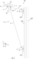
- Fig. 5 shows a schematic illustration in a perspective view of a fastening system 10 according to another embodiment of the invention.
- the support structure 11 is configured as a frame of an aircraft 100.
- the at least partly spherical shaped bearing portion 12 is configured as a buckling reinforcement.
- the sliding rail 102 may be configured as a rectangular profile having a groove for the sliding elements 103.
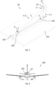
- Fig. 6 shows a schematic illustration of an aircraft 100 according to another embodiment of the invention with a fastening system 10 for compensating tolerances when fastening a cabin fitting element 101 to a frame 11 of the aircraft 100.
- the frame 11 forms the fuselage, for example. Due to the adjustability in X- and Y-direction the cabin fitting element 101, for example an overhead storage compartment, can be aligned properly, which leads to a pleasant cabin impression. This can be applied without compromising on the crash load path of the frame 11.
- the X-direction here corresponds to a flight direction of the aircraft 100.
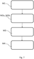
- Fig. 7 shows a schematic block diagram of an assembly method for compensating tolerances when fastening a component 101 to a support structure 11 of a means of transport according to another embodiment of the invention.
- the assembly method is suitable for compensating tolerances when fastening a cabin fitting element 101 to a frame 11 of an aircraft 100.
- the assembly method comprises a step of positioning M1 the component 101 in relation to the frame 11 of the aircraft 100.
- the assembly method comprises a step of providing M2a a first fastening device 1-1, wherein the second end portion 3 is positively locked to the component 101.
- the first fastening device 1-1 can substantially be configured as the fastening device of Fig. 1-5 .
- the assembly method comprises a step of providing M2b a second fastening device 1-2, wherein the second end portion 3 is positively locked to the component 101.
- the second fastening device 1-2 can substantially be configured as the fastening device of Fig. 1-5 .
- the second end portions 3 or hip bodies of both fastening devices 1-1, 1-2 can be attached to a sliding element 103 in a sliding rail 102.
- three hip bodies 3 can be guided with a locking pin into structural interfaces.
- the assembly method comprises a step of aligning M3 the first end portion 2 of the first fastening device 1-1 to an at least partly spherical shaped bearing portion 12 of the support structure 11 such that the first end portion 2 can be positively locked to the support structure 11.
- Aligning M3 may include sliding of the fastening system 10 in the situation before fixing the fastening system 10.
- the first fastening device 1-1 can be slid relative to the support structure along the sliding rail 102 of the component, while the second end portion 3 is positively locked to the component 101.
- the sliding rail 102 can be used as a fixation element until the first and second end portions are frictionally locked, for example.
- the first end portion 2 of the second fastening device 1-2 is thereby aligned together with the first end portion 2 of the first fastening device 1-1 in the step of aligning M3.
- the step aligning M3 includes a coordinated rotation of both at least partly spherical shaped bearing shells 2, 3 of the first fastening device 1-1 about their sphere center point. Since the first end portion 2 and the second end portion 3 of each fastening device 1 is fixedly connected to the rod body 5, rotating the first or the second end portion leads to a corresponding rotation of the second or first end portion, respectively.
- the assembly method further comprises a step of fixing M4 the first 2 and second end portions 3 after the step of aligning M3 such that the first 2 and second end portions 3 are frictionally locked.
- the first and second fastening device are fixed in position when the final position is reached.
- Final locking of the screws could be the last step, for instance.
Landscapes
- Engineering & Computer Science (AREA)
- General Engineering & Computer Science (AREA)
- Mechanical Engineering (AREA)
- Aviation & Aerospace Engineering (AREA)
- Connection Of Plates (AREA)
Priority Applications (1)
| Application Number | Priority Date | Filing Date | Title |
|---|---|---|---|
| EP23191484.7A EP4509727A1 (fr) | 2023-08-15 | 2023-08-15 | Système de fixation, aéronef et procédé de montage pour compenser les tolérances |
Applications Claiming Priority (1)
| Application Number | Priority Date | Filing Date | Title |
|---|---|---|---|
| EP23191484.7A EP4509727A1 (fr) | 2023-08-15 | 2023-08-15 | Système de fixation, aéronef et procédé de montage pour compenser les tolérances |
Publications (1)
| Publication Number | Publication Date |
|---|---|
| EP4509727A1 true EP4509727A1 (fr) | 2025-02-19 |
Family
ID=87575823
Family Applications (1)
| Application Number | Title | Priority Date | Filing Date |
|---|---|---|---|
| EP23191484.7A Pending EP4509727A1 (fr) | 2023-08-15 | 2023-08-15 | Système de fixation, aéronef et procédé de montage pour compenser les tolérances |
Country Status (1)
| Country | Link |
|---|---|
| EP (1) | EP4509727A1 (fr) |
Citations (3)
| Publication number | Priority date | Publication date | Assignee | Title |
|---|---|---|---|---|
| US4958603A (en) * | 1989-02-22 | 1990-09-25 | General Motors Corporation | Brace for connecting an auxiliary component to an internal combustion engine |
| US20040216284A1 (en) * | 2001-09-14 | 2004-11-04 | Belisle John I | Exhaust system clamp |
| US20190193871A1 (en) * | 2017-12-22 | 2019-06-27 | Airbus Operations Gmbh | Fastening system for fastening a component on a fuselage structure |
-
2023
- 2023-08-15 EP EP23191484.7A patent/EP4509727A1/fr active Pending
Patent Citations (3)
| Publication number | Priority date | Publication date | Assignee | Title |
|---|---|---|---|---|
| US4958603A (en) * | 1989-02-22 | 1990-09-25 | General Motors Corporation | Brace for connecting an auxiliary component to an internal combustion engine |
| US20040216284A1 (en) * | 2001-09-14 | 2004-11-04 | Belisle John I | Exhaust system clamp |
| US20190193871A1 (en) * | 2017-12-22 | 2019-06-27 | Airbus Operations Gmbh | Fastening system for fastening a component on a fuselage structure |
Similar Documents
| Publication | Publication Date | Title |
|---|---|---|
| EP3350063B1 (fr) | Coque de carrosserie d'automobile | |
| EP2530010A1 (fr) | Panneau intégralement raidi | |
| US20100327113A1 (en) | Design of aircraft frames | |
| US8505851B2 (en) | Profile comprising at least one hollow profile section | |
| EP3501994A1 (fr) | Aéronef et procédé de production d'un aéronef | |
| US8973870B2 (en) | Wall component for an aircraft | |
| EP4509727A1 (fr) | Système de fixation, aéronef et procédé de montage pour compenser les tolérances | |
| WO2023033989A1 (fr) | Ensemble pied modulaire pour siège passager | |
| EP3476714B1 (fr) | Mécanismes, systèmes et procédés permettant un ajustement des surfaces aérodynamiques | |
| EP1748924A1 (fr) | Encadrement de hublot pour avion | |
| EP4582340A1 (fr) | Système de fixation, aéronef, procédé de montage | |
| EP1748923B1 (fr) | Châssis de hublot pour avion | |
| US20220396359A1 (en) | Support pallet for an airplane seat unit | |
| US10399320B2 (en) | Assembling jig for mounting panel structure elements onto a surface of a CFRP panel | |
| US20190152365A1 (en) | Method for forming a vehicle reinforcing member | |
| EP4122827A1 (fr) | Système de rail de siège d'un espace intérieur d'un véhicule | |
| EP3895936B1 (fr) | Armature de siège d'aéronef présentant une meilleure réponse dynamique | |
| EP4530483A1 (fr) | Dispositif de fixation pour fixer un élément mécanique à une structure de support, système de fixation, procédé de fixation et procédé de détachement | |
| CN219487711U (zh) | 一种轻量化飞行器机体结构 | |
| EP4541711A1 (fr) | Dispositif de fixation pour une structure de support d'un système aérodynamique et procédé de fourniture d'un dispositif de fixation | |
| EP4563463A1 (fr) | Élément de support, agencement de fixation et véhicule le comprenant | |
| EP4563462A1 (fr) | Gant de fixation, agencement de fixation, véhicule le comprenant et procédé de fixation d'une structure de montage sur une structure de support | |
| US20250269906A1 (en) | Rear structure of vehicle body | |
| EP4596222A1 (fr) | Poutre composite pour armature de siège d'aéronef | |
| EP4692581A1 (fr) | Système d'accouplement, structure de fixation et véhicule |
Legal Events
| Date | Code | Title | Description |
|---|---|---|---|
| PUAI | Public reference made under article 153(3) epc to a published international application that has entered the european phase |
Free format text: ORIGINAL CODE: 0009012 |
|
| STAA | Information on the status of an ep patent application or granted ep patent |
Free format text: STATUS: THE APPLICATION HAS BEEN PUBLISHED |
|
| AK | Designated contracting states |
Kind code of ref document: A1 Designated state(s): AL AT BE BG CH CY CZ DE DK EE ES FI FR GB GR HR HU IE IS IT LI LT LU LV MC ME MK MT NL NO PL PT RO RS SE SI SK SM TR |
|
| STAA | Information on the status of an ep patent application or granted ep patent |
Free format text: STATUS: REQUEST FOR EXAMINATION WAS MADE |
|
| 17P | Request for examination filed |
Effective date: 20250801 |