EP4509719A1 - Fan and air conditioning device - Google Patents
Fan and air conditioning device Download PDFInfo
- Publication number
- EP4509719A1 EP4509719A1 EP24772547.6A EP24772547A EP4509719A1 EP 4509719 A1 EP4509719 A1 EP 4509719A1 EP 24772547 A EP24772547 A EP 24772547A EP 4509719 A1 EP4509719 A1 EP 4509719A1
- Authority
- EP
- European Patent Office
- Prior art keywords
- blade
- fan
- porous portion
- vertex
- plate
- Prior art date
- Legal status (The legal status is an assumption and is not a legal conclusion. Google has not performed a legal analysis and makes no representation as to the accuracy of the status listed.)
- Granted
Links
Images






Classifications
-
- F—MECHANICAL ENGINEERING; LIGHTING; HEATING; WEAPONS; BLASTING
- F04—POSITIVE - DISPLACEMENT MACHINES FOR LIQUIDS; PUMPS FOR LIQUIDS OR ELASTIC FLUIDS
- F04D—NON-POSITIVE-DISPLACEMENT PUMPS
- F04D17/00—Radial-flow pumps, e.g. centrifugal pumps; Helico-centrifugal pumps
- F04D17/08—Centrifugal pumps
-
- F—MECHANICAL ENGINEERING; LIGHTING; HEATING; WEAPONS; BLASTING
- F04—POSITIVE - DISPLACEMENT MACHINES FOR LIQUIDS; PUMPS FOR LIQUIDS OR ELASTIC FLUIDS
- F04D—NON-POSITIVE-DISPLACEMENT PUMPS
- F04D29/00—Details, component parts, or accessories
- F04D29/26—Rotors specially for elastic fluids
- F04D29/28—Rotors specially for elastic fluids for centrifugal or helico-centrifugal pumps for radial-flow or helico-centrifugal pumps
- F04D29/281—Rotors specially for elastic fluids for centrifugal or helico-centrifugal pumps for radial-flow or helico-centrifugal pumps for fans or blowers
- F04D29/282—Rotors specially for elastic fluids for centrifugal or helico-centrifugal pumps for radial-flow or helico-centrifugal pumps for fans or blowers the leading edge of each vane being substantially parallel to the rotation axis
-
- F—MECHANICAL ENGINEERING; LIGHTING; HEATING; WEAPONS; BLASTING
- F04—POSITIVE - DISPLACEMENT MACHINES FOR LIQUIDS; PUMPS FOR LIQUIDS OR ELASTIC FLUIDS
- F04D—NON-POSITIVE-DISPLACEMENT PUMPS
- F04D29/00—Details, component parts, or accessories
- F04D29/02—Selection of particular materials
- F04D29/023—Selection of particular materials especially adapted for elastic fluid pumps
-
- F—MECHANICAL ENGINEERING; LIGHTING; HEATING; WEAPONS; BLASTING
- F04—POSITIVE - DISPLACEMENT MACHINES FOR LIQUIDS; PUMPS FOR LIQUIDS OR ELASTIC FLUIDS
- F04D—NON-POSITIVE-DISPLACEMENT PUMPS
- F04D29/00—Details, component parts, or accessories
- F04D29/26—Rotors specially for elastic fluids
- F04D29/28—Rotors specially for elastic fluids for centrifugal or helico-centrifugal pumps for radial-flow or helico-centrifugal pumps
- F04D29/30—Vanes
-
- F—MECHANICAL ENGINEERING; LIGHTING; HEATING; WEAPONS; BLASTING
- F04—POSITIVE - DISPLACEMENT MACHINES FOR LIQUIDS; PUMPS FOR LIQUIDS OR ELASTIC FLUIDS
- F04D—NON-POSITIVE-DISPLACEMENT PUMPS
- F04D29/00—Details, component parts, or accessories
- F04D29/40—Casings; Connections of working fluid
- F04D29/42—Casings; Connections of working fluid for radial or helico-centrifugal pumps
- F04D29/4206—Casings; Connections of working fluid for radial or helico-centrifugal pumps especially adapted for elastic fluid pumps
- F04D29/4226—Fan casings
- F04D29/424—Double entry casings
-
- F—MECHANICAL ENGINEERING; LIGHTING; HEATING; WEAPONS; BLASTING
- F04—POSITIVE - DISPLACEMENT MACHINES FOR LIQUIDS; PUMPS FOR LIQUIDS OR ELASTIC FLUIDS
- F04D—NON-POSITIVE-DISPLACEMENT PUMPS
- F04D29/00—Details, component parts, or accessories
- F04D29/66—Combating cavitation, whirls, noise, vibration or the like; Balancing
- F04D29/661—Combating cavitation, whirls, noise, vibration or the like; Balancing especially adapted for elastic fluid pumps
- F04D29/663—Sound attenuation
- F04D29/664—Sound attenuation by means of sound absorbing material
-
- F—MECHANICAL ENGINEERING; LIGHTING; HEATING; WEAPONS; BLASTING
- F24—HEATING; RANGES; VENTILATING
- F24F—AIR-CONDITIONING; AIR-HUMIDIFICATION; VENTILATION; USE OF AIR CURRENTS FOR SCREENING
- F24F1/00—Room units for air-conditioning, e.g. separate or self-contained units or units receiving primary air from a central station
- F24F1/0007—Indoor units, e.g. fan coil units
- F24F1/0018—Indoor units, e.g. fan coil units characterised by fans
- F24F1/0022—Centrifugal or radial fans
-
- F—MECHANICAL ENGINEERING; LIGHTING; HEATING; WEAPONS; BLASTING
- F05—INDEXING SCHEMES RELATING TO ENGINES OR PUMPS IN VARIOUS SUBCLASSES OF CLASSES F01-F04
- F05D—INDEXING SCHEME FOR ASPECTS RELATING TO NON-POSITIVE-DISPLACEMENT MACHINES OR ENGINES, GAS-TURBINES OR JET-PROPULSION PLANTS
- F05D2300/00—Materials; Properties thereof
- F05D2300/50—Intrinsic material properties or characteristics
- F05D2300/514—Porosity
Definitions
- the present disclosure relates to a fan and an air conditioner.
- Patent Document 1 discloses a sirocco fan as a fan. Blades of the sirocco fan are fixed to an upper fixed frame and a lower disk. The entirety of each blade of the sirocco fan is made of a porous material, such as metal, synthetic resin, or ceramic.
- Patent Document 1 Japanese Unexamined Patent Publication No. S63-032196
- the present disclosure improves the quietness of a fan while increasing the strength of a blade.
- a first aspect is directed to a fan.
- the fan includes: a plate (36) having a discoidal shape and configured to rotate about an axis (X); an annular ring portion (37) having an annular ring shape and located apart from the plate (36) in an axial direction of the axis (X); and a blade (35) located between the plate (36) and the annular ring portion (37) and having one end (35a) in the axial direction of the axis (X) joined to the plate (36) and the other end (35b) in the axial direction joined to the annular ring portion (37), part of the blade (35) being a porous portion (51), a joint portion (35e) between the blade (35) and the plate (36) or a joint portion (35f) between the blade (35) and the annular ring portion (37) being a non-porous portion (52).
- the joint portions (35e, 35f), where stress is easily concentrated are configured as the non-porous portion (52), thereby making it possible to increase the strength of the blade (35). It is also possible to reduce the airflow separation since part of the blade is the porous portion (51). The reduction in the airflow separation improves the quietness. It is thus possible to improve the quietness while increasing the strength of the blade (35).
- a second aspect is an embodiment of the first aspect.
- the porous portion (51) is located at a separation portion (35g) where airflow separation along the blade (35) occurs.
- the porous portion (51) located at the separation portion (35g) effectively reduces the airflow separation. It is thus possible to improve the quietness.
- a third aspect is an embodiment of the first aspect.
- the porous portion (51) includes a leading edge (35c) of the blade (35).
- the leading edge (35c), where the airflow separation easily occurs is configured as the porous portion (51), thereby reducing the airflow separation effectively. It is thus possible to improve the quietness.
- a fourth aspect is an embodiment of the second or third aspect.
- the joint portion (35e) between the blade (35) and the plate (36) is an entirety of the one end (35a) of the blade (35)
- the joint portion (35f) between the blade (35) and the annular ring portion (37) is a portion of the blade (35) at a trailing edge (35d) and the other end (35b)
- the porous portion (51) is located in a region that is 90% or less of the blade height (H), and 90% or less of the blade chord length (L) from the leading edge (35c).
- the porous portion (51) is located as widely as possible, it is possible to improve the quietness.
- the region where the non-porous portion (52) is located can be ensured, it is possible to increase the strength of the blade (35).
- a fifth aspect is an embodiment of the fourth aspect.
- a length from the leading edge (35c) to an end of the porous portion (51) closer to the trailing edge (35d) in a direction perpendicular to the axial direction is longer at a portion closer to the other end (35b) than at a portion closer to the one end (35a).
- the region where the porous portion (51) is located is narrow. It is thus possible to increase the strength of the blade (35).
- a sixth aspect is an embodiment of the fourth or fifth aspect.
- the porous portion (51) is located in a region defined by connecting a first vertex (P1), a second vertex (P2), and a third vertex (P3) by straight lines or curves, the first vertex (P1) being a point of the blade (35) at the other end (35b) and at the leading edge (35c), the second vertex (P2) being a point at 90% of the blade height (H) from the first vertex (P1), the third vertex (P3) being a point at 90% of the blade chord length (L) from the first vertex (P1), as viewed from a rotational direction about the axis (X).
- the porous portion (51) is located at a large part of the leading edge, it is possible to improve the quietness.
- the region of the non-porous portion (52) around the joint portions (35e, 35f) can be as wide as possible. It is thus possible to increase the strength of the blade (35).
- a seventh aspect is an embodiment of any one of the first to sixth aspects.
- the fan is a centrifugal fan.
- a relatively great centrifugal force is generated in the centrifugal fan. Stress caused by the centrifugal force concentrates on the joint portions (35e, 35f) easily.
- the joint portions (35e, 35f) are configured as the non-porous portion (52), thereby making it possible to ensure the strength of the blade (35). It is also possible to reduce the airflow separation since part of the blade is the porous portion (51). The reduction in the airflow separation improves the quietness. It is thus possible to improve the quietness while increasing the strength of the blade (35) against the centrifugal force.
- An eighth aspect is directed to an air conditioner including the fan of any one of the first to seventh aspects.
- a fan device (30) is applied to an air conditioner (10).
- the air conditioner (10) conditions indoor air.
- the air conditioner (10) of this embodiment adjusts the temperature of air.
- the air conditioner (10) is an outdoor air conditioner that supplies outdoor air to an indoor space. As illustrated in FIG. 1 , the air conditioner (10) has an indoor unit (10a) disposed above the ceiling.
- the indoor unit (10a) has an air conditioning casing (11), and the fan device (30) and an indoor heat exchanger (17) housed in the air conditioning casing (11).
- the air conditioning casing (11) is in a horizontally oriented rectangular parallelepiped box shape.
- the air conditioning casing (11) has a first side plate (12) and a second side plate (13) facing each other.
- An outside air suction port (14) is formed in the first side plate (12), and an air supply port (15) is formed in the second side plate (13).
- the outside air suction port (14) communicates with an outdoor space through a suction duct.
- the air supply port (15) communicates with the indoor space via an air supply duct.
- An air passage (16) through which air flows is formed from the outside air suction port (14) to the air supply port (15) in the air conditioning casing (11).
- the fan device (30) is disposed in the air passage (16). To be exact, the fan device (30) is a sirocco fan device.
- the indoor heat exchanger (17) causes heat exchange between the air and a refrigerant.
- the indoor heat exchanger (17) is connected to a refrigerant circuit.
- the refrigerant circuit has a compressor, an outdoor heat exchanger, an expansion valve, and the indoor heat exchanger (17).
- the refrigerant circuit circulates the refrigerant to perform a vapor compression refrigeration cycle.
- the compressor and the outdoor heat exchanger are provided in an outdoor unit.
- the compressor and the fan device (30) are operated, and the indoor heat exchanger (17) functions as an evaporator.
- the air having flowed into the air passage (16) through the outside air suction port (14) passes through the indoor heat exchanger (17).
- the indoor heat exchanger (17) the air is cooled by the refrigerant that evaporates.
- the air cooled in the indoor heat exchanger (17) is supplied to the indoor space through the air supply port (15) and the air supply duct.
- the compressor and the fan device (30) are operated, and the indoor heat exchanger (17) functions as a condenser (radiator).
- the air having flowed into the air passage (16) through the outside air suction port (14) passes through the indoor heat exchanger (17).
- the indoor heat exchanger (17) the air is heated by the refrigerant that condenses.
- the air heated in the indoor heat exchanger (17) is supplied to the indoor space through the air supply port (15) and the air supply duct.
- the fan device (30) illustrated in FIGS. 1 to 3 has a motor (31), a drive shaft (32) rotationally driven by the motor (31), a fan (33) coupled to the drive shaft (32), and a casing (40) housing the fan (33).
- the motor (31) is supported by a motor support (34).
- the drive shaft (32) is coupled to the motor (31) and extends horizontally.
- the fan device (30) is installed upright, in which the drive shaft (32) of the motor (31) extends horizontally.
- the fan (33) is coupled to the drive shaft (32).
- the fan (33) is a centrifugal fan.
- the fan (33) has a plurality of blades (35) arranged in the rotational direction of the fan (33). In the case of FIG. 3 , the rotational direction of the fan (33) is counterclockwise about the axis (X).
- the casing (40) has a cylindrical casing body (40a) and a discharge portion (40b) extending in the direction of a tangent to the casing body (40a) from an outer peripheral portion of the casing body (40a).
- the casing body (40a) has a first wall (41), a second wall (42), and a peripheral wall (43).
- the first wall (41) is formed on one end side of the casing body (40a) in the axial direction
- the second wall (42) is formed on the other end side of the casing body (40a) in the axial direction.
- the first wall (41) is located closer to the motor (31) with respect to the fan (33), and the second wall (42) is located opposite to the motor (31) with respect to the fan (33).
- the first wall (41) and the second wall (42) has a discoidal shape.
- a first suction port (47) is formed in a center portion of the first wall (41).
- a second suction port (44) is formed in a center portion of the second wall (42).
- the peripheral wall (43) surrounds an outer peripheral portion of the fan (33).
- the peripheral wall (43) has a substantially arc shape along the fan (33).
- the discharge portion (40b) forms a duct communicating with the inside of the casing body (40a).
- the discharge portion (40b) is formed in a rectangular tubular shape with both ends in the axial direction open.
- the opening on one end of the discharge portion (40b) in the axial direction is connected to the inside of the casing body (40a).
- the opening on the other end of the discharge portion (40b) in the axial direction forms a blow-out port (45).
- a fan flow path (46) through which the air flows is formed in the casing (40) from the first suction port (47) and the second suction port (44) to the blow-out port (45).
- the fan (33) illustrated in FIG. 4 has the plurality of blades (35), a discoidal plate (36), a first ring (37) located apart from the plate (36) in the axial direction of the axis (X), and a second ring (38) located between the plate (36) and the first ring (37) in the axial direction of the axis (X).
- the blades (35), the first ring (37), and the second ring (38) are arranged on both sides of the plate (36) in the axial direction of the axis (X).
- the blades (35) are arranged parallel with the axial direction of axis (X).
- the blades (35) are located between the plate (36) and the first ring (37).
- One end (35a) of the blade (35) in the axial direction of the axis (X) is joined to the plate (36), and the other end (35b) in the axial direction is joined to the first ring (37).
- the inner side of the blade (35) in a radial direction perpendicular to the axial direction of the axis (X) is a leading edge (35c), and the outer side is a trailing edge (35d).
- a portion of the blade (35) closer to the plate (36) in the axial direction of the axis (X) will be referred to as one end side, and a portion closer to the first ring (37) will be referred to as the other end side.
- the plate (36) has a boss (36a) at the center.
- the boss (36a) is coupled to the drive shaft (32).
- a joint portion (35e) between the blade (35) and the plate (36) is the entirety of the one end (35a) of the blade (35).
- the blades (35) and the plate (36) are integrally joined to each other by integral molding or insertion.
- the first ring (37) is disposed concentrically with the plate (36).
- the first ring (37) is disposed outside the blades (35) in the radial direction described above.
- a joint portion (35f) between the blade (35) and the first ring (37) is a portion of the blade (35) at the trailing edge (35d) and the other end (35b).
- the blades (35) and the first ring (37) are integrally joined to each other by integral molding or welding.
- the second ring (38) is disposed concentrically with the plate (36).
- the second ring (38) is located in the middle of the blades (35) in the axial direction of the axis (X).
- the second ring (38) is disposed outside the blades (35) in the radial direction described above.
- the second ring (38) is joined to the trailing edges (35d) of the blades (35).
- the blades (35) and the second ring (38) are integrally joined to each other by integral molding or welding.
- the porous portion (51) has a plurality of fine pores penetrating the blade (35) from a positive pressure surface to a negative pressure surface.
- the porous portion (51) is made of resin, ceramics, or metal, for example.
- the resin is a foamed resin, for example.
- the metal and the ceramic are porous sintered bodies.
- the average diameter of the pores (air gaps) of the porous portion (51) is, for example, in a range of 15 ⁇ m to 300 ⁇ m.
- a portion other than the porous portion (51) is a non-porous portion (52).
- the joint portion (35e) between the blade (35) and the plate (36) and the joint portion (35f) between the blade (35) and the first ring (37) are the non-porous portion (52).
- a joint portion between the blade (35) and the second ring (38) is also the non-porous portion (52).
- the non-porous portion (52) has no pores penetrating the blade (35) from the positive pressure surface to the negative pressure surface, and is solid.
- the non-porous portion (52) is made of, for example, synthetic resin.
- the strength of the non-porous portion (52) is higher than that of the porous portion (51).
- the porous portion (51) and the non-porous portion (52) are integrally formed by, for example, insert molding, adhesion, or fitting.
- the porous portion (51) is located at a separation portion (35g) where airflow separation along the blade (35) occurs.
- a vortex flow is easily generated.
- the vortex flow causes a problem of greatly disturbing the flow of air and generating noise.
- the porous portion (51) is provided at the separation portion (35g).
- the separation portion (35g) is the leading edge (35c) and a top portion (35h) of the curve of the blade (35) on the negative pressure surface.
- the airflow separation occurs particularly easily on the negative pressure surface of the leading edge (35c) in the course of flowing from the inner side to the outer side in the radial direction.
- the porous portion (51) is located at the substantially entire leading edge (35c).
- the porous portion (51) includes at least part of the separation portion (35g). It is not necessary that the entire separation portion (35g) is the porous portion (51).
- a dimension from the other end (35b) of the blade (35) to the plate (36) is defined as a blade height (H).
- a dimension from the leading edge (35c) to the trailing edge (35d) of the blade (35) is defined as a blade chord length (L).
- a point of the blade (35) at the other end (35b) and at the leading edge (35c) as viewed from the rotational direction is defined as a first vertex (P1).
- a point of the blade (35) at 90% of the blade height (H) from the first vertex (P1) in the axial direction of the axis (X) is defined as a second vertex (P2).
- a point of the blade (35) at 90% of the blade chord length (L) from the first vertex (P1) is defined as a third vertex (P3).
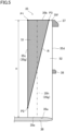
- the porous portion (51) is located in a region that is 90% or less of the blade height (H) from the other end (35b) and 90% or less of the blade chord length (L) from the leading edge (35c). More specifically, the porous portion (51) is located in a specific region (R) defined by connecting the first vertex (P1), the second vertex (P2), and the third vertex (P3) by straight lines or curves. In this embodiment, the porous portion (51) is located in the entire specific region (R).
- the shape of the porous portion (51) as viewed from the rotational direction is a triangular shape. The shape of the porous portion (51) is not limited to the triangular shape.
- the length from the leading edge (35c) to the end of the porous portion (51) closer to the trailing edge in the radial direction is longer at a portion closer to the other end (35b) of the blade (35) than at a portion closer to the one end (35a) of the blade (35). More specifically, the length from the leading edge (35c) to the end of the porous portion (51) closer to the trailing edge is longer as it is closer to the other end (35b) of the blade (35), and the longest at the other end (35b) of the blade (35).
- part of the blade (35) is the porous portion (51), and the joint portion (35e) between the blade (35) and the plate (36) and the joint portion (35f) between the blade (35) and the first ring (37) are the non-porous portion (52).
- the joint portions (35e, 35f), where stress is easily concentrated, are configured as the non-porous portion (52), thereby making it possible to increase the strength against centrifugal force. It is also possible to reduce the airflow separation since part of the blade (35) is the porous portion (51). The reduction in the airflow separation improves the quietness of the fan device (30). It is thus possible to improve the quietness of the fan device (30) while increasing the strength of the blade (35) against the centrifugal force.
- the porous portion (51) is located at the separation portion (35g) where airflow separation along the blade (35) occurs.
- the porous portion (51) located at the separation portion (35g) effectively reduces the airflow separation. It is thus possible to improve the quietness of the fan device (30).
- the porous portion (51) includes the leading edge (35c) of the blade (35).
- the leading edge (35c), where airflow separation easily occurs, is configured as the porous portion (51), thereby reducing the airflow separation effectively. It is thus possible to improve the quietness of the fan device (30).
- the porous portion (51) is located in a region that is 90% or less of the blade height (H) from the other end (35b) of the blade (35) and 90% or less of the blade chord length (L) from the leading edge (35c). Since the porous portion (51) is located as widely as possible, it is possible to improve the quietness of the fan device (30).
- the length from the leading edge (35c) to the end of the porous portion (51) closer to the trailing edge (35d) in the radial direction of the axis (X) is longer at a portion closer to the other end (35b) than at a portion closer to the one end (35a).
- the region where the porous portion (51) is located is narrow. It is thus possible to increase the strength of the blade (35) against the centrifugal force.
- the porous portion (51) is located in a region defined by connecting the first vertex (P1), the second vertex (P2), and the third vertex (P3) by straight lines or curves. Since the porous portion (51) is located at a large part of the leading edge (35c), it is possible to improve the quietness of the fan device (30).
- the region of the non-porous portion (52) around the joint portions (35e, 35f) can be as wide as possible. It is thus possible to increase the strength of the blade (35) against the centrifugal force.
- the fan device (30) described above may have configurations as those of the following variations. Differences from the above embodiment will be described below.
- the region where a porous portion (151) is located differs in the first variation. As illustrated in FIG. 7 , the porous portion (151) is not provided at a portion near the other end (35b) and the trailing edge (35d) of the blade (35) in the specific region (R). A non-porous portion (152) is located in this portion of the specific region (R).
- the region of the non-porous portion (152) is wide around the joint portion (35f) between the blade (35) and the first ring (37). It is thus possible to increase the strength of the blade (35) against the centrifugal force.
- the separation portion (35g) is the porous portion (151), it is possible to improve the quietness of the fan device (30).
- the region where a porous portion (251) is located differs in the second variation.
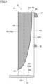
- the porous portion (251) is located in a region defined by connecting the first vertex (P1) and the second vertex (P2) by a straight line, connecting the first vertex (P1) and the third vertex (P3) by a straight line, and connecting the second vertex (P2) and the third vertex (P3) by a curve.
- the shape of the porous portion (251) as viewed from the rotational direction is a quarter ellipse having a long side from the first vertex (P1) to the second vertex (P2) and a short side from the first vertex (P1) to the third vertex (P3).
- the length from the leading edge (35c) to the end of the porous portion (251) closer to the trailing edge is longer as it is closer to the other end (35b) of the blade (35), and the longest at the other end (35b) of the blade (35).
- the region of the porous portion (251) is made as wide as possible at the top portion (35h) of the curve of the blade (35) on the negative pressure surface. It is thus possible to improve the quietness of the fan device (30).
- the joint portions (35e, 35f) are a non-porous portion (252), it is possible to increase the strength of the blade (35) against the centrifugal force.
- the region where a porous portion (351) is located differs in the third variation.
- the shape of the porous portion (351) as viewed from the rotational direction is a rectangle having a long side from the first vertex (P1) to the second vertex (P2) and a short side from the first vertex (P1) to the third vertex (P3).
- the region of the porous portion (351) is made as wide as possible at the top portion (35h) of the curve of the blade (35) on the negative pressure surface. It is thus possible to improve the quietness of the fan device (30).
- the joint portions (35e, 35f) are a non-porous portion (352), it is possible to increase the strength of the blade (35) against the centrifugal force.
- a porous portion (451) is located at the other end (35b) of the blade (35) at least in a region between the third vertex (P3) and the leading edge (35c).
- at least a portion of the other end (35b) of the blade (35) between the third vertex (P3) and the trailing edge (35d) is a non-porous portion (452).
- the porous portion (451) may extend such that the length from the leading edge (35c) be longer than 90% of the blade chord length (L) in a region closer to the one end (35a) than the other end (35b) of the blade (35).
- the joint portion (35f) between the blade (35) and the first ring (37) may be the entirety of the other end (35b) of the blade (35) instead of part of the other end (35b).
- the entirety of the other end (35b) of the blade (35) may be the non-porous portion.
- a portion of the fan (33) where the non-porous portion (52, 152, 252, 352, 452) is formed may be either the joint portion (35e) between the blade (35) and the plate (36) or the joint portion (35f) between the blade (35) and the first ring (37).
- the fan (33) may be a cross-flow fan.
- the configuration of this embodiment employed to the cross-flow fan increases the strength of the blade (35) and improves the quietness.
- some of a plurality of fans coupled to each other may have blades (35) whose one end (35a) and the other end (35b) are both joined to annular ring portions.
- the joint portion between the annular ring portion and each of the one end (35a) and other end (35b) of the blade (35) may be a non-porous portion.
- the fan device (30) may be installed sideways, in which the axis (X) extends in the vertical direction, or may be installed such that the axis (X) extends in another direction.
- the fan device (30) may be of a one-side suction type, in which only the second wall (42) has a suction port.
- the air conditioner (10) may be an air purifier that purifies air in a target space, a ventilation apparatus that ventilates a target space, or a humidity control apparatus that controls a humidity in a target space.
- the indoor unit (10a) may be of a ceiling hanging type, a wall hanging type, or a floor mounting type.
- the present disclosure is useful for a fan.
Landscapes
- Engineering & Computer Science (AREA)
- Mechanical Engineering (AREA)
- General Engineering & Computer Science (AREA)
- Chemical & Material Sciences (AREA)
- Combustion & Propulsion (AREA)
- Structures Of Non-Positive Displacement Pumps (AREA)
- Air-Conditioning Room Units, And Self-Contained Units In General (AREA)
Abstract
Description
- The present disclosure relates to a fan and an air conditioner.
- Patent Document 1 discloses a sirocco fan as a fan. Blades of the sirocco fan are fixed to an upper fixed frame and a lower disk. The entirety of each blade of the sirocco fan is made of a porous material, such as metal, synthetic resin, or ceramic.
- Patent Document 1:
Japanese Unexamined Patent Publication No. S63-032196 - When the fan rotates, stress tends to be concentrated on a joint portion between the blades and other components. In the structure in which the entirety of each blade is formed as a porous portion as in the fan of Patent Document 1, the strength is lowered at the j oint portion.
- The present disclosure improves the quietness of a fan while increasing the strength of a blade.
- A first aspect is directed to a fan. The fan includes: a plate (36) having a discoidal shape and configured to rotate about an axis (X); an annular ring portion (37) having an annular ring shape and located apart from the plate (36) in an axial direction of the axis (X); and a blade (35) located between the plate (36) and the annular ring portion (37) and having one end (35a) in the axial direction of the axis (X) joined to the plate (36) and the other end (35b) in the axial direction joined to the annular ring portion (37), part of the blade (35) being a porous portion (51), a joint portion (35e) between the blade (35) and the plate (36) or a joint portion (35f) between the blade (35) and the annular ring portion (37) being a non-porous portion (52).
- According to the first aspect, the joint portions (35e, 35f), where stress is easily concentrated, are configured as the non-porous portion (52), thereby making it possible to increase the strength of the blade (35). It is also possible to reduce the airflow separation since part of the blade is the porous portion (51). The reduction in the airflow separation improves the quietness. It is thus possible to improve the quietness while increasing the strength of the blade (35).
- A second aspect is an embodiment of the first aspect. In the second aspect, the porous portion (51) is located at a separation portion (35g) where airflow separation along the blade (35) occurs.
- According to the second aspect, the porous portion (51) located at the separation portion (35g) effectively reduces the airflow separation. It is thus possible to improve the quietness.
- A third aspect is an embodiment of the first aspect. In the third aspect, the porous portion (51) includes a leading edge (35c) of the blade (35).
- According to the third aspect, the leading edge (35c), where the airflow separation easily occurs, is configured as the porous portion (51), thereby reducing the airflow separation effectively. It is thus possible to improve the quietness.
- A fourth aspect is an embodiment of the second or third aspect. In the fourth aspect, the joint portion (35e) between the blade (35) and the plate (36) is an entirety of the one end (35a) of the blade (35), the joint portion (35f) between the blade (35) and the annular ring portion (37) is a portion of the blade (35) at a trailing edge (35d) and the other end (35b), and a dimension from the one end (35a) of the blade (35) to the plate (36) is defined as a blade height (H) and a dimension from the leading edge (35c) to the trailing edge (35d) of the blade (35) is defined as a blade chord length (L), and the porous portion (51) is located in a region that is 90% or less of the blade height (H), and 90% or less of the blade chord length (L) from the leading edge (35c).
- According to the fourth aspect, since the porous portion (51) is located as widely as possible, it is possible to improve the quietness. In addition, since the region where the non-porous portion (52) is located can be ensured, it is possible to increase the strength of the blade (35).
- A fifth aspect is an embodiment of the fourth aspect. In the fifth aspect, a length from the leading edge (35c) to an end of the porous portion (51) closer to the trailing edge (35d) in a direction perpendicular to the axial direction is longer at a portion closer to the other end (35b) than at a portion closer to the one end (35a).
- According to the fifth aspect, around the joint portion between the blade (35) and the plate (36), the region where the porous portion (51) is located is narrow. It is thus possible to increase the strength of the blade (35).
- A sixth aspect is an embodiment of the fourth or fifth aspect. In the sixth aspect, the porous portion (51) is located in a region defined by connecting a first vertex (P1), a second vertex (P2), and a third vertex (P3) by straight lines or curves, the first vertex (P1) being a point of the blade (35) at the other end (35b) and at the leading edge (35c), the second vertex (P2) being a point at 90% of the blade height (H) from the first vertex (P1), the third vertex (P3) being a point at 90% of the blade chord length (L) from the first vertex (P1), as viewed from a rotational direction about the axis (X).
- According to the sixth aspect, since the porous portion (51) is located at a large part of the leading edge, it is possible to improve the quietness. The region of the non-porous portion (52) around the joint portions (35e, 35f) can be as wide as possible. It is thus possible to increase the strength of the blade (35).
- A seventh aspect is an embodiment of any one of the first to sixth aspects. In the seventh aspect, the fan is a centrifugal fan.
- According to the seventh aspect, a relatively great centrifugal force is generated in the centrifugal fan. Stress caused by the centrifugal force concentrates on the joint portions (35e, 35f) easily. The joint portions (35e, 35f) are configured as the non-porous portion (52), thereby making it possible to ensure the strength of the blade (35). It is also possible to reduce the airflow separation since part of the blade is the porous portion (51). The reduction in the airflow separation improves the quietness. It is thus possible to improve the quietness while increasing the strength of the blade (35) against the centrifugal force.
- An eighth aspect is directed to an air conditioner including the fan of any one of the first to seventh aspects.
-
-
FIG. 1 is a longitudinal sectional view illustrating a schematic configuration of an air conditioner. -
FIG. 2 is a side view of a fan. -
FIG. 3 is a sectional view taken along line III-III ofFIG. 2 . -
FIG. 4 is a perspective view of the fan. -
FIG. 5 is a side view of a blade as viewed from a rotational direction about an axis. -
FIG. 6 is an enlarged view of the blade as viewed from the axial direction of the axis. -
FIG. 7 is a side view of a blade according to a first variation. -
FIG. 8 is a side view of a blade according to a second variation. -
FIG. 9 is a side view of a blade according to a third variation. -
FIG. 10 is a side view of a blade according to another embodiment. - Embodiments of the present disclosure will be described in detail below with reference to the drawings. The present disclosure is not limited to the embodiments shown below, and various changes can be made within the scope without departing from the technical concept of the present disclosure. Each of the drawings is intended to illustrate the present disclosure conceptually, and dimensions, ratios, or numbers may be exaggerated or simplified as necessary for the sake of ease of understanding.
- A fan device (30) is applied to an air conditioner (10). The air conditioner (10) conditions indoor air. The air conditioner (10) of this embodiment adjusts the temperature of air. The air conditioner (10) is an outdoor air conditioner that supplies outdoor air to an indoor space. As illustrated in
FIG. 1 , the air conditioner (10) has an indoor unit (10a) disposed above the ceiling. The indoor unit (10a) has an air conditioning casing (11), and the fan device (30) and an indoor heat exchanger (17) housed in the air conditioning casing (11). - The air conditioning casing (11) is in a horizontally oriented rectangular parallelepiped box shape. The air conditioning casing (11) has a first side plate (12) and a second side plate (13) facing each other. An outside air suction port (14) is formed in the first side plate (12), and an air supply port (15) is formed in the second side plate (13). The outside air suction port (14) communicates with an outdoor space through a suction duct. The air supply port (15) communicates with the indoor space via an air supply duct. An air passage (16) through which air flows is formed from the outside air suction port (14) to the air supply port (15) in the air conditioning casing (11).
- The fan device (30) is disposed in the air passage (16). To be exact, the fan device (30) is a sirocco fan device.
- The indoor heat exchanger (17) causes heat exchange between the air and a refrigerant. The indoor heat exchanger (17) is connected to a refrigerant circuit. The refrigerant circuit has a compressor, an outdoor heat exchanger, an expansion valve, and the indoor heat exchanger (17). The refrigerant circuit circulates the refrigerant to perform a vapor compression refrigeration cycle. The compressor and the outdoor heat exchanger are provided in an outdoor unit.
- In a cooling operation, the compressor and the fan device (30) are operated, and the indoor heat exchanger (17) functions as an evaporator. The air having flowed into the air passage (16) through the outside air suction port (14) passes through the indoor heat exchanger (17). In the indoor heat exchanger (17), the air is cooled by the refrigerant that evaporates. The air cooled in the indoor heat exchanger (17) is supplied to the indoor space through the air supply port (15) and the air supply duct.
- In a heating operation, the compressor and the fan device (30) are operated, and the indoor heat exchanger (17) functions as a condenser (radiator). The air having flowed into the air passage (16) through the outside air suction port (14) passes through the indoor heat exchanger (17). In the indoor heat exchanger (17), the air is heated by the refrigerant that condenses. The air heated in the indoor heat exchanger (17) is supplied to the indoor space through the air supply port (15) and the air supply duct.
- The fan device (30) illustrated in
FIGS. 1 to 3 has a motor (31), a drive shaft (32) rotationally driven by the motor (31), a fan (33) coupled to the drive shaft (32), and a casing (40) housing the fan (33). The motor (31) is supported by a motor support (34). The drive shaft (32) is coupled to the motor (31) and extends horizontally. The fan device (30) is installed upright, in which the drive shaft (32) of the motor (31) extends horizontally. - The fan (33) is coupled to the drive shaft (32). The fan (33) is a centrifugal fan. The fan (33) has a plurality of blades (35) arranged in the rotational direction of the fan (33). In the case of
FIG. 3 , the rotational direction of the fan (33) is counterclockwise about the axis (X). - The casing (40) has a cylindrical casing body (40a) and a discharge portion (40b) extending in the direction of a tangent to the casing body (40a) from an outer peripheral portion of the casing body (40a).
- The casing body (40a) has a first wall (41), a second wall (42), and a peripheral wall (43). The first wall (41) is formed on one end side of the casing body (40a) in the axial direction, and the second wall (42) is formed on the other end side of the casing body (40a) in the axial direction. The first wall (41) is located closer to the motor (31) with respect to the fan (33), and the second wall (42) is located opposite to the motor (31) with respect to the fan (33). The first wall (41) and the second wall (42) has a discoidal shape. A first suction port (47) is formed in a center portion of the first wall (41). A second suction port (44) is formed in a center portion of the second wall (42). The peripheral wall (43) surrounds an outer peripheral portion of the fan (33). The peripheral wall (43) has a substantially arc shape along the fan (33).
- The discharge portion (40b) forms a duct communicating with the inside of the casing body (40a). The discharge portion (40b) is formed in a rectangular tubular shape with both ends in the axial direction open. The opening on one end of the discharge portion (40b) in the axial direction is connected to the inside of the casing body (40a). The opening on the other end of the discharge portion (40b) in the axial direction forms a blow-out port (45). A fan flow path (46) through which the air flows is formed in the casing (40) from the first suction port (47) and the second suction port (44) to the blow-out port (45).
- The fan (33) illustrated in
FIG. 4 has the plurality of blades (35), a discoidal plate (36), a first ring (37) located apart from the plate (36) in the axial direction of the axis (X), and a second ring (38) located between the plate (36) and the first ring (37) in the axial direction of the axis (X). The blades (35), the first ring (37), and the second ring (38) are arranged on both sides of the plate (36) in the axial direction of the axis (X). - The blades (35) are arranged parallel with the axial direction of axis (X). The blades (35) are located between the plate (36) and the first ring (37). One end (35a) of the blade (35) in the axial direction of the axis (X) is joined to the plate (36), and the other end (35b) in the axial direction is joined to the first ring (37). The inner side of the blade (35) in a radial direction perpendicular to the axial direction of the axis (X) is a leading edge (35c), and the outer side is a trailing edge (35d). In this specification, a portion of the blade (35) closer to the plate (36) in the axial direction of the axis (X) will be referred to as one end side, and a portion closer to the first ring (37) will be referred to as the other end side.
- The plate (36) has a boss (36a) at the center. The boss (36a) is coupled to the drive shaft (32). A joint portion (35e) between the blade (35) and the plate (36) is the entirety of the one end (35a) of the blade (35). The blades (35) and the plate (36) are integrally joined to each other by integral molding or insertion.
- The first ring (37) is disposed concentrically with the plate (36). The first ring (37) is disposed outside the blades (35) in the radial direction described above. A joint portion (35f) between the blade (35) and the first ring (37) is a portion of the blade (35) at the trailing edge (35d) and the other end (35b). The blades (35) and the first ring (37) are integrally joined to each other by integral molding or welding.
- The second ring (38) is disposed concentrically with the plate (36). The second ring (38) is located in the middle of the blades (35) in the axial direction of the axis (X). The second ring (38) is disposed outside the blades (35) in the radial direction described above. The second ring (38) is joined to the trailing edges (35d) of the blades (35). The blades (35) and the second ring (38) are integrally joined to each other by integral molding or welding.
- Part of the blade (35) is a porous portion (51). The porous portion (51) has a plurality of fine pores penetrating the blade (35) from a positive pressure surface to a negative pressure surface. The porous portion (51) is made of resin, ceramics, or metal, for example. The resin is a foamed resin, for example. The metal and the ceramic are porous sintered bodies. The average diameter of the pores (air gaps) of the porous portion (51) is, for example, in a range of 15 µm to 300 µm. The porosity of the porous portion (51) (= the total volume of the air gaps / the entire volume of the porous portion) is, for example, in a range of 35% to 90%.
- Of the blade (35), a portion other than the porous portion (51) is a non-porous portion (52). The joint portion (35e) between the blade (35) and the plate (36) and the joint portion (35f) between the blade (35) and the first ring (37) are the non-porous portion (52). A joint portion between the blade (35) and the second ring (38) is also the non-porous portion (52). The non-porous portion (52) has no pores penetrating the blade (35) from the positive pressure surface to the negative pressure surface, and is solid. The non-porous portion (52) is made of, for example, synthetic resin. The strength of the non-porous portion (52) is higher than that of the porous portion (51). The porous portion (51) and the non-porous portion (52) are integrally formed by, for example, insert molding, adhesion, or fitting.
- The porous portion (51) is located at a separation portion (35g) where airflow separation along the blade (35) occurs. When the airflow separation occurs at the separation portion (35g), a vortex flow is easily generated. The vortex flow causes a problem of greatly disturbing the flow of air and generating noise. In this embodiment, in order to solve the above problem, the porous portion (51) is provided at the separation portion (35g).
- As illustrated in
FIGS. 5 and6 , the separation portion (35g) is the leading edge (35c) and a top portion (35h) of the curve of the blade (35) on the negative pressure surface. In the case of the sirocco fan as in this embodiment, the airflow separation occurs particularly easily on the negative pressure surface of the leading edge (35c) in the course of flowing from the inner side to the outer side in the radial direction. Thus, the porous portion (51) is located at the substantially entire leading edge (35c). The porous portion (51) includes at least part of the separation portion (35g). It is not necessary that the entire separation portion (35g) is the porous portion (51). - An area where the porous portion (51) is located will be described in detail. As illustrated in
FIGS. 5 and6 , a dimension from the other end (35b) of the blade (35) to the plate (36) is defined as a blade height (H). A dimension from the leading edge (35c) to the trailing edge (35d) of the blade (35) is defined as a blade chord length (L). A point of the blade (35) at the other end (35b) and at the leading edge (35c) as viewed from the rotational direction is defined as a first vertex (P1). A point of the blade (35) at 90% of the blade height (H) from the first vertex (P1) in the axial direction of the axis (X) is defined as a second vertex (P2). A point of the blade (35) at 90% of the blade chord length (L) from the first vertex (P1) is defined as a third vertex (P3). - As illustrated in
FIG. 5 , the porous portion (51) is located in a region that is 90% or less of the blade height (H) from the other end (35b) and 90% or less of the blade chord length (L) from the leading edge (35c). More specifically, the porous portion (51) is located in a specific region (R) defined by connecting the first vertex (P1), the second vertex (P2), and the third vertex (P3) by straight lines or curves. In this embodiment, the porous portion (51) is located in the entire specific region (R). In this embodiment, the shape of the porous portion (51) as viewed from the rotational direction is a triangular shape. The shape of the porous portion (51) is not limited to the triangular shape. - In this embodiment, the length from the leading edge (35c) to the end of the porous portion (51) closer to the trailing edge in the radial direction is longer at a portion closer to the other end (35b) of the blade (35) than at a portion closer to the one end (35a) of the blade (35). More specifically, the length from the leading edge (35c) to the end of the porous portion (51) closer to the trailing edge is longer as it is closer to the other end (35b) of the blade (35), and the longest at the other end (35b) of the blade (35).
- In this embodiment, part of the blade (35) is the porous portion (51), and the joint portion (35e) between the blade (35) and the plate (36) and the joint portion (35f) between the blade (35) and the first ring (37) are the non-porous portion (52). The joint portions (35e, 35f), where stress is easily concentrated, are configured as the non-porous portion (52), thereby making it possible to increase the strength against centrifugal force. It is also possible to reduce the airflow separation since part of the blade (35) is the porous portion (51). The reduction in the airflow separation improves the quietness of the fan device (30). It is thus possible to improve the quietness of the fan device (30) while increasing the strength of the blade (35) against the centrifugal force.
- In this embodiment, the porous portion (51) is located at the separation portion (35g) where airflow separation along the blade (35) occurs. The porous portion (51) located at the separation portion (35g) effectively reduces the airflow separation. It is thus possible to improve the quietness of the fan device (30).
- In this embodiment, the porous portion (51) includes the leading edge (35c) of the blade (35). The leading edge (35c), where airflow separation easily occurs, is configured as the porous portion (51), thereby reducing the airflow separation effectively. It is thus possible to improve the quietness of the fan device (30).
- In this embodiment, the porous portion (51) is located in a region that is 90% or less of the blade height (H) from the other end (35b) of the blade (35) and 90% or less of the blade chord length (L) from the leading edge (35c). Since the porous portion (51) is located as widely as possible, it is possible to improve the quietness of the fan device (30).
- In this embodiment, the length from the leading edge (35c) to the end of the porous portion (51) closer to the trailing edge (35d) in the radial direction of the axis (X) is longer at a portion closer to the other end (35b) than at a portion closer to the one end (35a). Around the joint portion (35e) between the blade (35) and the plate (36), the region where the porous portion (51) is located is narrow. It is thus possible to increase the strength of the blade (35) against the centrifugal force.
- In a sixth aspect, the porous portion (51) is located in a region defined by connecting the first vertex (P1), the second vertex (P2), and the third vertex (P3) by straight lines or curves. Since the porous portion (51) is located at a large part of the leading edge (35c), it is possible to improve the quietness of the fan device (30). The region of the non-porous portion (52) around the joint portions (35e, 35f) can be as wide as possible. It is thus possible to increase the strength of the blade (35) against the centrifugal force.
- The fan device (30) described above may have configurations as those of the following variations. Differences from the above embodiment will be described below.
- The region where a porous portion (151) is located differs in the first variation. As illustrated in
FIG. 7 , the porous portion (151) is not provided at a portion near the other end (35b) and the trailing edge (35d) of the blade (35) in the specific region (R). A non-porous portion (152) is located in this portion of the specific region (R). - In the first variation, the region of the non-porous portion (152) is wide around the joint portion (35f) between the blade (35) and the first ring (37). It is thus possible to increase the strength of the blade (35) against the centrifugal force. In the first variation, since great part of the separation portion (35g) is the porous portion (151), it is possible to improve the quietness of the fan device (30).
- The region where a porous portion (251) is located differs in the second variation. As illustrated in
FIG. 8 , in the second variation, the porous portion (251) is located in a region defined by connecting the first vertex (P1) and the second vertex (P2) by a straight line, connecting the first vertex (P1) and the third vertex (P3) by a straight line, and connecting the second vertex (P2) and the third vertex (P3) by a curve. Specifically, the shape of the porous portion (251) as viewed from the rotational direction is a quarter ellipse having a long side from the first vertex (P1) to the second vertex (P2) and a short side from the first vertex (P1) to the third vertex (P3). In the second variation, the length from the leading edge (35c) to the end of the porous portion (251) closer to the trailing edge is longer as it is closer to the other end (35b) of the blade (35), and the longest at the other end (35b) of the blade (35). - In the second variation, it is possible to make the region of the porous portion (251) as wide as possible at the top portion (35h) of the curve of the blade (35) on the negative pressure surface. It is thus possible to improve the quietness of the fan device (30). In the second variation, since the joint portions (35e, 35f) are a non-porous portion (252), it is possible to increase the strength of the blade (35) against the centrifugal force.
- The region where a porous portion (351) is located differs in the third variation. As illustrated in
FIG. 9 , the shape of the porous portion (351) as viewed from the rotational direction is a rectangle having a long side from the first vertex (P1) to the second vertex (P2) and a short side from the first vertex (P1) to the third vertex (P3). - In the third variation, it is possible to make the region of the porous portion (351) as wide as possible at the top portion (35h) of the curve of the blade (35) on the negative pressure surface. It is thus possible to improve the quietness of the fan device (30). In the third variation, since the joint portions (35e, 35f) are a non-porous portion (352), it is possible to increase the strength of the blade (35) against the centrifugal force.
- A porous portion (451) is located at the other end (35b) of the blade (35) at least in a region between the third vertex (P3) and the leading edge (35c). In other words, at least a portion of the other end (35b) of the blade (35) between the third vertex (P3) and the trailing edge (35d) is a non-porous portion (452). As illustrated in
FIG. 10 , the porous portion (451) may extend such that the length from the leading edge (35c) be longer than 90% of the blade chord length (L) in a region closer to the one end (35a) than the other end (35b) of the blade (35). - The joint portion (35f) between the blade (35) and the first ring (37) may be the entirety of the other end (35b) of the blade (35) instead of part of the other end (35b). In this case, the entirety of the other end (35b) of the blade (35) may be the non-porous portion.
- A portion of the fan (33) where the non-porous portion (52, 152, 252, 352, 452) is formed may be either the joint portion (35e) between the blade (35) and the plate (36) or the joint portion (35f) between the blade (35) and the first ring (37).
- Although the centrifugal fan has been described as the fan (33), the fan (33) may be a cross-flow fan. The configuration of this embodiment employed to the cross-flow fan increases the strength of the blade (35) and improves the quietness. In the case of the cross-flow fan, some of a plurality of fans coupled to each other may have blades (35) whose one end (35a) and the other end (35b) are both joined to annular ring portions. In this case, for some of the plurality of fans, the joint portion between the annular ring portion and each of the one end (35a) and other end (35b) of the blade (35) may be a non-porous portion.
- The fan device (30) may be installed sideways, in which the axis (X) extends in the vertical direction, or may be installed such that the axis (X) extends in another direction.
- The fan device (30) may be of a one-side suction type, in which only the second wall (42) has a suction port.
- The air conditioner (10) may be an air purifier that purifies air in a target space, a ventilation apparatus that ventilates a target space, or a humidity control apparatus that controls a humidity in a target space.
- The indoor unit (10a) may be of a ceiling hanging type, a wall hanging type, or a floor mounting type.
- While the embodiment and variations thereof have been described above, it will be understood that various changes in form and details may be made without departing from the spirit and scope of the claims. The embodiment, the variation thereof, and the other embodiments may be combined and replaced with each other without deteriorating intended functions of the present disclosure.
- The ordinal numbers such as "first," "second," "third," ... , described above are used to distinguish the terms to which these expressions are given, and do not limit the number and order of the terms.
- As described above, the present disclosure is useful for a fan.
-
- 33
- Fan
- 5
- Blade
- 35a
- One End
- 35b
- Other End
- 35c
- Leading Edge
- 35d
- Trailing Edge
- 35e
- Joint Portion
- 35f
- Joint Portion
- 35g
- Separation Portion
- 36
- Plate
- 37
- First Ring (Annular Ring Portion)
- 51
- Porous Portion
- 52
- Non-Porous Portion
- 151
- Porous Portion
- 152
- Non-Porous Portion
- 251
- Porous Portion
- 252
- Non-Porous Portion
- 351
- Porous Portion
- 352
- Non-Porous Portion
- 451
- Porous Portion
- 452
- Non-Porous Portion
- H
- Blade Height
- L
- Blade Chord Length
- P1
- First Vertex
- P2
- Second Vertex
- P3
- Third Vertex
- X
- Axis
Claims (8)
- A fan comprising:a plate (36) having a discoidal shape and configured to rotate about an axis (X);an annular ring portion (37) having an annular ring shape and located apart from the plate (36) in an axial direction of the axis (X); anda blade (35) located between the plate (36) and the annular ring portion (37) and having one end (35a) in the axial direction of the axis (X) joined to the plate (36) and the other end (35b) in the axial direction joined to the annular ring portion (37),part of the blade (35) being a porous portion (51, 151, 251, 351, 451),a joint portion (35e) between the blade (35) and the plate (36) or a joint portion (35f) between the blade (35) and the annular ring portion (37) being a non-porous portion (52, 152, 252, 352, 452).
- The fan of claim 1, wherein
the porous portion (51, 151, 251, 351, 451) is located at a separation portion (35g) where airflow separation along the blade (35) occurs. - The fan of claim 1, wherein
the porous portion (51, 151, 251, 351, 451) includes a leading edge (35c) of the blade (35). - The fan of claim 2 or 3, whereinthe joint portion (35e) between the blade (35) and the plate (36) is an entirety of the one end (35a) of the blade (35),the joint portion (35f) between the blade (35) and the annular ring portion (37) is a portion of the blade (35) at a trailing edge (35d) and the other end (35b), anda dimension from the plate (36) to the other end (35b) of the blade (35) is defined as a blade height (H) and a dimension from the leading edge (35c) to the trailing edge (35d) of the blade (35) is defined as a blade chord length (L), and the porous portion (51, 151, 251, 351) is located in a region that is 90% or less of the blade height (H), and 90% or less of the blade chord length (L) from the leading edge (35c).
- The fan of claim 4, wherein
a length from the leading edge (35c) to an end of the porous portion (51, 151, 251, 351) closer to the trailing edge (35d) in a direction perpendicular to the axial direction is longer at a portion closer to the other end (35b) than at a portion closer to the one end (35a). - The fan of claim 4 or 5, wherein
the porous portion (51, 151, 251, 351) is located in a region defined by connecting a first vertex (P1), a second vertex (P2), and a third vertex (P3) by straight lines or curves, the first vertex (P1) being a point of the blade (35) at the other end (35b) and at the leading edge (35c), the second vertex (P2) being a point at 90% of the blade height (H) from the first vertex (P1), the third vertex (P3) being a point at 90% of the blade chord length (L) from the first vertex (P1), as viewed from a rotational direction about the axis (X). - The fan of any one of claims 1 to 6, wherein the fan is a centrifugal fan.
- An air conditioner comprising the fan (33) of any one of claims 1 to 7.
Applications Claiming Priority (2)
| Application Number | Priority Date | Filing Date | Title |
|---|---|---|---|
| JP2023107918 | 2023-06-30 | ||
| PCT/JP2024/021750 WO2025004867A1 (en) | 2023-06-30 | 2024-06-14 | Fan and air conditioning device |
Publications (3)
| Publication Number | Publication Date |
|---|---|
| EP4509719A1 true EP4509719A1 (en) | 2025-02-19 |
| EP4509719A4 EP4509719A4 (en) | 2025-08-20 |
| EP4509719B1 EP4509719B1 (en) | 2026-05-13 |
Family
ID=92932696
Family Applications (1)
| Application Number | Title | Priority Date | Filing Date |
|---|---|---|---|
| EP24772547.6A Active EP4509719B1 (en) | 2023-06-30 | 2024-06-14 | Fan and air conditioning device |
Country Status (5)
| Country | Link |
|---|---|
| US (1) | US20260085689A1 (en) |
| EP (1) | EP4509719B1 (en) |
| JP (1) | JP7716025B2 (en) |
| CN (1) | CN121358959A (en) |
| WO (1) | WO2025004867A1 (en) |
Family Cites Families (3)
| Publication number | Priority date | Publication date | Assignee | Title |
|---|---|---|---|---|
| JPS6332196A (en) | 1986-07-25 | 1988-02-10 | N D C Kk | Low noise fan |
| JPH02207196A (en) * | 1989-02-03 | 1990-08-16 | Matsushita Refrig Co Ltd | Impeller for centrifugal fan |
| JP2754862B2 (en) * | 1990-04-27 | 1998-05-20 | 松下電器産業株式会社 | Blower impeller |
-
2024
- 2024-06-14 WO PCT/JP2024/021750 patent/WO2025004867A1/en not_active Ceased
- 2024-06-14 JP JP2024096772A patent/JP7716025B2/en active Active
- 2024-06-14 CN CN202480042028.3A patent/CN121358959A/en active Pending
- 2024-06-14 EP EP24772547.6A patent/EP4509719B1/en active Active
-
2025
- 2025-11-25 US US19/400,922 patent/US20260085689A1/en active Pending
Also Published As
| Publication number | Publication date |
|---|---|
| EP4509719B1 (en) | 2026-05-13 |
| US20260085689A1 (en) | 2026-03-26 |
| JP7716025B2 (en) | 2025-07-31 |
| WO2025004867A1 (en) | 2025-01-02 |
| CN121358959A (en) | 2026-01-16 |
| EP4509719A4 (en) | 2025-08-20 |
| JP2025009916A (en) | 2025-01-20 |
Similar Documents
| Publication | Publication Date | Title |
|---|---|---|
| US12044250B2 (en) | Centrifugal blower, air-blowing apparatus, air-conditioning apparatus, and refrigeration cycle apparatus | |
| US10634168B2 (en) | Blower and air-conditioning apparatus including the same | |
| US11319961B2 (en) | Centrifugal blower, air conditioner, and refrigeration cycle apparatus | |
| JP6625305B1 (en) | Blower, air conditioner indoor unit and air conditioner | |
| JPH0658564A (en) | Air conditioner | |
| US11480192B2 (en) | Cutoff for a blower housing | |
| EP4509719B1 (en) | Fan and air conditioning device | |
| WO2020136788A1 (en) | Centrifugal blower, blower device, air conditioner, and refrigeration cycle device | |
| JP7640885B2 (en) | Fans and air conditioners | |
| JP4441665B2 (en) | Air conditioner outdoor unit and air conditioner | |
| WO2023223383A1 (en) | Cross flow fan, blowing device, and refrigeration cycle device | |
| WO2024038573A1 (en) | Blower fan, multi-blade centrifugal blower, and air-conditioning indoor unit | |
| HK40069680A (en) | Centrifugal blower, blowing device, air conditioner, and refrigeration cycle device | |
| KR100720578B1 (en) | Air conditioner | |
| HK40025188B (en) | Centrifugal blower, blowing device, air conditioner, and refrigeration cycle device | |
| HK40025188A (en) | Centrifugal blower, blowing device, air conditioner, and refrigeration cycle device |
Legal Events
| Date | Code | Title | Description |
|---|---|---|---|
| STAA | Information on the status of an ep patent application or granted ep patent |
Free format text: STATUS: UNKNOWN |
|
| STAA | Information on the status of an ep patent application or granted ep patent |
Free format text: STATUS: THE INTERNATIONAL PUBLICATION HAS BEEN MADE |
|
| PUAI | Public reference made under article 153(3) epc to a published international application that has entered the european phase |
Free format text: ORIGINAL CODE: 0009012 |
|
| STAA | Information on the status of an ep patent application or granted ep patent |
Free format text: STATUS: REQUEST FOR EXAMINATION WAS MADE |
|
| 17P | Request for examination filed |
Effective date: 20240925 |
|
| AK | Designated contracting states |
Kind code of ref document: A1 Designated state(s): AL AT BE BG CH CY CZ DE DK EE ES FI FR GB GR HR HU IE IS IT LI LT LU LV MC ME MK MT NL NO PL PT RO RS SE SI SK SM TR |
|
| A4 | Supplementary search report drawn up and despatched |
Effective date: 20250718 |
|
| RIC1 | Information provided on ipc code assigned before grant |
Ipc: F04D 29/30 20060101AFI20250714BHEP Ipc: F04D 29/02 20060101ALI20250714BHEP Ipc: F04D 29/66 20060101ALI20250714BHEP |
|
| P01 | Opt-out of the competence of the unified patent court (upc) registered |
Free format text: CASE NUMBER: UPC_APP_3794_4509719/2025 Effective date: 20250820 |
|
| GRAP | Despatch of communication of intention to grant a patent |
Free format text: ORIGINAL CODE: EPIDOSNIGR1 |
|
| STAA | Information on the status of an ep patent application or granted ep patent |
Free format text: STATUS: GRANT OF PATENT IS INTENDED |
|
| DAV | Request for validation of the european patent (deleted) | ||
| DAX | Request for extension of the european patent (deleted) | ||
| INTG | Intention to grant announced |
Effective date: 20260130 |
|
| GRAS | Grant fee paid |
Free format text: ORIGINAL CODE: EPIDOSNIGR3 |
|
| GRAA | (expected) grant |
Free format text: ORIGINAL CODE: 0009210 |
|
| STAA | Information on the status of an ep patent application or granted ep patent |
Free format text: STATUS: THE PATENT HAS BEEN GRANTED |
|
| AK | Designated contracting states |
Kind code of ref document: B1 Designated state(s): AL AT BE BG CH CY CZ DE DK EE ES FI FR GB GR HR HU IE IS IT LI LT LU LV MC ME MK MT NL NO PL PT RO RS SE SI SK SM TR |
|
| REG | Reference to a national code |
Ref country code: CH Ref legal event code: F10 Free format text: ST27 STATUS EVENT CODE: U-0-0-F10-F00 (AS PROVIDED BY THE NATIONAL OFFICE) Effective date: 20260513 Ref country code: GB Ref legal event code: FG4D |
|
| REG | Reference to a national code |
Ref country code: DE Ref legal event code: R096 Ref document number: 602024004845 Country of ref document: DE |
|
| REG | Reference to a national code |
Ref country code: IE Ref legal event code: FG4D |
|
| PGFP | Annual fee paid to national office [announced via postgrant information from national office to epo] |
Ref country code: DE Payment date: 20260622 Year of fee payment: 3 |
|
| PGFP | Annual fee paid to national office [announced via postgrant information from national office to epo] |
Ref country code: AT Payment date: 20260714 Year of fee payment: 3 |