EP4509662A1 - Operation mechanism of front loader and working vehicle - Google Patents
Operation mechanism of front loader and working vehicle Download PDFInfo
- Publication number
- EP4509662A1 EP4509662A1 EP24186402.4A EP24186402A EP4509662A1 EP 4509662 A1 EP4509662 A1 EP 4509662A1 EP 24186402 A EP24186402 A EP 24186402A EP 4509662 A1 EP4509662 A1 EP 4509662A1
- Authority
- EP
- European Patent Office
- Prior art keywords
- moving
- moving pin
- operation lever
- front loader
- recess
- Prior art date
- Legal status (The legal status is an assumption and is not a legal conclusion. Google has not performed a legal analysis and makes no representation as to the accuracy of the status listed.)
- Pending
Links
Images




Classifications
-
- E—FIXED CONSTRUCTIONS
- E02—HYDRAULIC ENGINEERING; FOUNDATIONS; SOIL SHIFTING
- E02F—DREDGING; SOIL-SHIFTING
- E02F9/00—Component parts of dredgers or soil-shifting machines, not restricted to one of the kinds covered by groups E02F3/00 - E02F7/00
- E02F9/20—Drives; Control devices
- E02F9/2004—Control mechanisms, e.g. control levers
Definitions
- the disclosure relates to a technique of an operation mechanism of a front loader and a working vehicle.
- JP 2017-91061 A discloses such a technique.
- the operation mechanism described in JP 2017-91061 A includes a loader lever, two push-pull wires, and the like.
- the loader lever is configured to be rockable in a left-right direction and a front-rear direction.
- the two push-pull wires couplet the loader lever and a loader valve.
- One of the two push-pull wires moves up and down in a case where the loader lever is rocked in the left-right direction.
- the other of the two push-pull wires moves up and down in a case where the loader lever is rocked in the front-rear direction.
- a spool of the loader valve is displaced by the vertical movement of the push-pull wire, and an arm of the front loader and a working tool (bucket) can be operated.
- One aspect of the present disclosure has been made in view of the above circumstances, and an object of the present disclosure is to provide an operation mechanism of a front loader and a working vehicle capable of reducing an influence of backlash of an operation lever.
- One aspect of the present disclosure includes: an operation lever; a moving member movable in a predetermined direction according to an operation of the operation lever and connected to a control valve; and a restriction mechanism configured to restrict movement of the moving member in a state where the operation lever is operated to a neutral position. According to one aspect of the present disclosure, the influence of backlash of the operation lever can be reduced by restricting the movement of the moving member.
- the restriction mechanism includes an abutment member capable of abutting on a surface of the moving member, and a biasing member configured to bias the abutment member toward the moving member.
- the influence of backlash of the operation lever can be reduced with a simple configuration.
- the moving member includes a first recess engageable with the abutment member in a state where the operation lever is operated to the neutral position. According to one aspect of the present disclosure, the influence of backlash of the operation lever can be effectively reduced.
- the moving member includes a second recess formed to extend along a moving direction of the moving member and configured to guide the abutment member. According to one aspect of the present disclosure, it is possible to suppress an increase in an operation load of the operation lever due to the provision of the restriction mechanism.
- One aspect of the present disclosure further includes a support member in which an accommodation portion that accommodates the moving member is formed, in which the restriction mechanism is provided in a communication hole that communicates an outer surface of the support member and the accommodation portion.
- the restriction mechanism can be easily provided from the outside of the support member.
- the moving member includes a rotation restriction portion configured to restrict rotation about an axis parallel to a moving direction of the moving member. According to one aspect of the present disclosure, it is possible to easily position the moving member with respect to the support member.
- the moving member includes a boom moving member configured to control an operation of a boom of the front loader, and a bucket moving member configured to control an operation of a bucket of the front loader. According to one aspect of the present disclosure, the influence of backlash of the operation lever in two operation directions can be reduced.
- One aspect of the present disclosure includes the above-described operation mechanism of a front loader. According to one aspect of the present disclosure, the influence of backlash of the operation lever can be reduced.
- the influence of backlash of the operation lever can be reduced.
- directions indicated by arrows U, D, F, B, L, and R in the drawings are defined as an upward direction, a downward direction, a forward direction, a backward direction, a left direction, and a right direction, respectively.
- a tractor 1 according to an embodiment of the disclosure will be described with reference to Fig. 1 .
- the tractor 1 mainly includes a machine body frame 2, an engine 3, a transmission case 4, front wheels 5, rear wheels 6, a bonnet 7, a cabin 8, a steering wheel 9, a seat 10, and a front loader 11.
- the machine body frame 2 is a frame-shaped member formed by appropriately combining a plurality of panel members.
- the machine body frame 2 is formed in a substantially rectangular shape in plan view.
- the machine body frame 2 is disposed with its longitudinal direction oriented in a front-rear direction.
- the engine 3 is fixed to a rear portion of the machine body frame 2.
- the transmission case 4 is fixed to a rear portion of the engine 3.
- a front portion of the machine body frame 2 is supported by the pair of left and right front wheels 5 through a front axle mechanism (not illustrated).
- a rear portion of the transmission case 4 is supported by the pair of left and right rear wheels 6 through a rear axle mechanism (not illustrated).
- the engine 3 is covered with the bonnet 7.
- Power of the engine 3 can be transmitted to the front wheels 5 through the front axle mechanism and can be transmitted to the rear wheels 6 through the rear axle mechanism after being shifted by a transmission device (not illustrated) accommodated in the transmission case 4.
- the front wheels 5 and the rear wheels 6 are rotationally driven by the power of the engine 3, and the tractor 1 can travel.
- the cabin 8 is provided behind the engine 3.
- a steering wheel 9 and various operation tools for adjusting a turning angle of the front wheels 5 are disposed in a front portion of the cabin 8.
- the seat 10 on which a driver sits is disposed substantially at a center of the cabin 8. Furthermore, an operation mechanism 20 for operating the front loader 11 is provided near the seat 10.
- the front loader 11 is attached to a front portion of the tractor 1.
- the front loader 11 includes a boom 12, a bucket 13, a boom cylinder 14, a bucket cylinder 15, a control valve 16, and the like.
- the boom 12 is disposed so as to extend forward and downward.
- the bucket 13 is detachably coupled to a front end portion of the boom 12.
- the control valve 16 is configured to be able to feed hydraulic pressure to the boom cylinder 14 and the bucket cylinder 15.
- the control valve 16 is disposed below the cabin 8.
- the boom 12 can be rotated with respect to a vehicle body by expansion and contraction of the boom cylinder 14 by the hydraulic pressure from the control valve 16.
- the bucket 13 can rotate with respect to the boom 12 when the bucket cylinder 15 is expanded and contracted by the hydraulic pressure from the control valve 16.
- the work of transporting earth and sand, and the like can be carried out while appropriately rotating the boom 12 and the bucket 13.
- the operation mechanism 20 is for operating the front loader 11 in accordance with an operation of an operator. As illustrated in Fig. 2 , the operation mechanism 20 includes a support member 30, a fixing pin 40, a moving pin 50, a cable 60, a coupling member 70, an operation lever 80, and a restriction mechanism 90. Note that Figs. 2 to 5 illustrate the operation mechanism 20 in a case where the operation lever 80 is located at a neutral position.
- the support member 30 illustrated in Figs. 2 , 3 , and 4B is a member for supporting various members (the fixing pin 40 and the like) of the operation mechanism 20.
- the support member 30 is formed in a substantially rectangular parallelepiped shape.
- the support member 30 is provided in the cabin 8.
- the support member 30 includes a first through hole 31, a second through hole 32, and a communication hole 33.
- the first through hole 31 and the second through hole 32 vertically penetrate the support member 30.
- the first through hole 31 and the second through hole 32 are formed in a substantially circular shape in plan view.
- the first through hole 31 is formed in a left front portion of the support member 30.
- the second through hole 32 is formed in each of a left rear portion and a right front portion of the support member 30.
- the second through hole 32 formed in the left rear portion of the support member 30 is referred to as a "left second through hole 32L”.
- the second through hole 32 formed in the right front portion of the support member 30 is referred to as a "right second through hole 32R".
- the communication hole 33 illustrated in Figs. 4B and 5 is a hole that allows the second through hole 32 and an outer surface of the support member 30 to communicate with each other.
- One communication hole 33 is formed for one second through hole 32.
- the communication hole 33 is formed to extend in the left-right direction.
- the communication hole 33 is formed in a substantially circular shape in side view.
- the communication hole 33 is formed so as to communicate the left second through hole 32L with a left side surface of the support member 30.
- the communication hole 33 is formed to communicate the right second through hole 32R with a right side surface of the support member 30.
- a female screw portion is formed (not illustrated) on an inner peripheral surface of each of the communication holes 33.
- the fixing pin 40 illustrated in Figs. 3 , 4A and 4B is a member fixed to the support member 30.
- the fixing pin 40 includes a columnar portion 41, a spherical portion 42, and a connection portion 43.
- the columnar portion 41 is a columnar portion whose axial direction is oriented in the vertical direction.
- the columnar portion 41 is fixed to the first through hole 31.
- the spherical portion 42 is a portion formed in a substantially spherical shape.
- the spherical portion 42 is formed above the columnar portion 41.
- the connection portion 43 is a portion that connects the columnar portion 41 and the spherical portion 42.
- the spherical portion 42 and the connection portion 43 are located above the support member 30.
- the moving pin 50 illustrated in Figs. 4B and 5 is a member relatively movable in the vertical direction with respect to the support member 30.
- the moving pin 50 is provided in each of the left and right second through holes 32L and 32R.
- the moving pin 50 provided in the left second through hole 32L is referred to as a "left moving pin 50L”.
- the moving pin 50 provided in the right second through hole 32R is referred to as a "right moving pin 50R".
- the configuration of the moving pin 50 will be described by taking the right moving pin 50R as an example.
- the moving pin 50 includes a columnar portion 51, a spherical portion 52, and a connection portion 53.
- the columnar portion 51 is a columnar portion whose axial direction is oriented in the vertical direction. An outer diameter of the columnar portion 51 is smaller than an inner diameter of the second through hole 32. The columnar portion 51 is accommodated in the second through hole 32. As illustrated in Figs. 5 and 6A , the columnar portion 51 includes a first recess 51a and a second recess 51b.
- the first recess 51a and the second recess 51b are formed to be recessed leftward (toward a center of the columnar portion 51) on an outer peripheral surface of the columnar portion 51.
- the first recess 51a is formed in a substantially hemispherical shape along a ball 92 of the restriction mechanism 90 described later.
- the first recess 51a is formed in a lower portion of the columnar portion 51.
- the second recess 51b is formed so as to extend in the vertical direction (moving direction of the moving pin 50) from the first recess 51a.
- a depth of the second recess 51b is shallower than that of the first recess 51a.
- a magnitude relationship between the depths of the first recess 51a and the second recess 51b is not limited to the present embodiment.
- the first recess 51a and the second recess 51b may have the same depth.
- the second recess 51b is formed on each of an upper side and a lower side of the first recess 51a. As illustrated in Fig. 6A , the second recess 51b on the upper side includes a sharp portion 51c and a straight portion 51d.
- the sharp portion 51c is a portion formed in a tapered shape in which a lateral width decreases toward the first recess 51a.
- the straight portion 51d is a portion extending in the vertical direction with a constant lateral width.
- the straight portion 51d is formed in a substantially arc shape in plan cross-sectional view (see Fig. 6B ).
- the straight portion 51d is formed to extend from the sharp portion 51c to an upper end portion of the columnar portion 51.
- the second recess 51b on the lower side includes only the sharp portion 51c of the above-described sharp portion 51c and straight portion 51d. Note that the second recess 51b on the lower side may include the straight portion 51d according to an amount of movement of the moving pin 50, a vertical position of the first recess 51a, and the like.
- the spherical portion 52 illustrated in Figs. 5 and 6A is formed above the columnar portion 51.
- the spherical portion 52 is formed in the same shape as the spherical portion 42 of the fixing pin 40.
- connection portion 53 is a portion that connects the columnar portion 51 and the spherical portion 52.
- the connection portion 53 is formed in a substantially columnar shape.
- a flat portion 53a is formed in the connection portion 53.
- the flat portion 53a is disposed above the first recess 51a and the second recess 51b so as to face rightward.
- the flat portion 53a is located above the second through hole 32.
- the cable 60 illustrated in Fig. 5 is for transmitting an operation force of the operation lever 80 to the control valve 16.
- the cable 60 is formed in a longitudinal shape (linear shape) and has flexibility.
- the cable 60 connects the left and right moving pins 50L and 50R and the control valve 16.
- the cable 60 includes an outer cable 61 and an inner cable 62.
- the outer cable 61 is formed so as to cover the inner cable 62. One end portion of the outer cable 61 is coupled to the support member 30. The other end portion of the outer cable 61 is fixed to the vehicle body in the vicinity of the control valve 16 illustrated in Fig. 1 .
- One end portion of the inner cable 62 illustrated in Fig. 5 protrudes upward from the one end portion of the outer cable 61 and is coupled to the moving pin 50.
- the other end portion of the inner cable 62 protrudes from the other end portion of the outer cable 61 and is coupled to the spool of the control valve 16 illustrated in Fig. 1 . More specifically, the other end portion of the outer cable 61 is coupled to the spool by inserting a pin into a hole portion formed in the spool.
- the coupling member 70 illustrated in Figs. 2 , 3 , and 4A is a member to which the operation lever 80 is coupled.
- the coupling member 70 is formed in a plate shape with a plate surface oriented in the vertical direction.
- the coupling member 70 is disposed above the support member 30.
- the coupling member 70 includes a first notch 71 and a second notch 72.
- the first notch 71 illustrated in Figs. 3 and 4A has a substantially semicircular cross-sectional shape with an opening facing downward, and is formed so as to extend from a left front end of the coupling member 70 to the right rear.
- the first notch 71 is formed in a left front portion of the coupling member 70 (above the first through hole 31).
- the spherical portion 42 of the fixing pin 40 is accommodated in the first notch 71.
- the second notch 72 is formed in a left rear portion (above the left second through hole 32) and a right front portion (above the right second through hole 32) of the coupling member 70.
- the second notch 72 at the left rear portion has a substantially semicircular cross-sectional shape with an opening facing downward, and is formed to extend forward from a rear side surface of the coupling member 70.
- the spherical portion 52 of the left moving pin 50L is accommodated in the second notch 72 at the left rear portion.
- the second notch 72 at the right front portion has a substantially semicircular cross-sectional shape with an opening facing downward, and is formed to extend leftward from a right side surface of the coupling member 70.
- the spherical portion 52 of the right moving pin 50R is accommodated in the second notch 72 at the right front portion.
- the operation lever 80 illustrated in Fig. 2 is a member that can be operated by an operator.
- the operation lever 80 is formed by appropriately bending a rod-like member.
- a lower end portion of the operation lever 80 is coupled to the coupling member 70.
- the lower end portion of the operation lever 80 is located at a position not overlapping with the fixing pin 40 and the moving pin 50 in plan view (see Figs. 4A and 4B ).
- the operation lever 80 is configured to be operable in the left-right direction and the front-rear direction from the neutral position.
- the coupling member 70 rocks left and right with the fixing pin 40 as a fulcrum.
- the right front portion of the coupling member 70 rocks up and down, and the right moving pin 50R accommodated in the second notch 72 of the right front portion is moved in the vertical direction.
- the right moving pin 50R slides in the vertical direction with respect to the right second through hole 32R of the support member 30.
- the cable 60 (inner cable 62) coupled to the right moving pin 50R is moved in the vertical direction, the spool of the control valve 16 is displaced, and the bucket cylinder 15 is controlled.
- the operator can operate the bucket 13 according to the operation of the operation lever 80 in the left-right direction.
- the coupling member 70 rocks back and forth with the fixing pin 40 as a fulcrum.
- the left rear portion of the coupling member 70 rocks up and down, and the left moving pin 50L accommodated in the second notch 72 of the left rear portion is moved in the vertical direction.
- the left moving pin 50L slides in the vertical direction with respect to the left second through hole 32L of the support member 30.
- the cable 60 inner cable 62 coupled to the left moving pin 50L is moved in the vertical direction, the spool of the control valve 16 is displaced, and the boom cylinder 14 is controlled.
- the operator can operate the boom 12 according to the operation of the operation lever 80 in the front-rear direction.
- the spool is not displaced (only the cable 60 moves) until the operation lever 80 is operated by a predetermined amount or more from the vicinity of the neutral position due to an influence of a gap generated between the outer cable 61 and the inner cable 62, a gap generated at a coupling portion between the spool and the cable 60 (between the hole portion of the spool and the pin), and the like.
- the operation lever 80 moves (backlash) near the center position unintentionally by the operator due to vibration or the like during traveling of the tractor 1.
- the restriction mechanism 90 illustrated in Figs. 4A, 4B and 5 restricts the movement of the moving pin 50 located at the neutral position to reduce the influence of the above-described backlash (backlash during traveling).
- the restriction mechanism 90 is provided on the support member 30.
- One restriction mechanism 90 is provided for one moving pin 50.
- the restriction mechanism 90 includes an accommodation member 91, a ball 92, and a spring 93.
- the accommodation member 91 illustrated in Fig. 5 is a member for accommodating the ball 92 and the spring 93.
- the accommodation member 91 is formed in a bottomed substantially cylindrical shape.
- the accommodation member 91 is disposed with an axial direction oriented in the left-right direction. Furthermore, the accommodation member 91 is disposed such that an opening faces the left side (second through hole 32).
- a male screw portion is formed on an outer peripheral surface of the accommodation member 91 (not illustrated).
- the accommodation member 91 is attached to the support member 30 by being screwed into the communication hole 33.
- the ball 92 is disposed in an opening of the support member 30 (an end portion on a side of the second through hole 32). A part of the ball 92 protrudes from the opening. The ball 92 abuts on (engages with) the first recess 51a of the moving pin 50 in a state where the operation lever 80 is located at the neutral position (state illustrated in Fig. 5 ).
- the spring 93 biases the ball 92 leftward (toward the moving pin 50).
- the spring 93 is accommodated in the accommodation member 91 and is disposed between a bottom (right end portion) of the accommodation member 91 and the ball 92.
- a biasing member that biases the ball 92 is not limited to the compression coil spring, and may be another type of spring or an elastic body such as resin.
- the restriction mechanism 90 in a case where the right moving pin 50R tries to move in the vertical direction in a state where the operation lever 80 is located at the neutral position, the ball 92 tries to climb over the first recess 51a. At this time, the ball 92 is pressed against the first recess 51a by the spring 93, and the movement of the moving pin 50R in the vertical direction is restricted.
- the operation lever 80 can be prevented from backlashing in the left-right direction near the neutral position due to vibration or the like during traveling of the tractor 1.
- the operator can move the moving pin 50 up and down against a biasing force of the spring 93.
- the second recess 51b abuts on the ball 92.
- the moving pin 50 moves in the vertical direction while the ball 92 is guided by the second recess 51b.
- the ball 92 is continuously released toward the second through hole 32 by the other recess (second recess 51b).
- the biasing force of the spring 93 can be made relatively small, so that it is possible to suppress an increase in the operation load after the operation lever 80 is moved from the neutral position, and it is possible to suppress a decrease in operability.
- the accommodation member 91 of the present embodiment is screwed into the communication hole 33. According to this configuration, the biasing force of the spring 93 can be easily adjusted by adjusting a screwing amount of the accommodation member 91 into the communication hole 33.
- the flat portion 53a of the moving pin 50 is disposed between the support member 30 and the coupling member 70 (see Fig. 3 ). With this configuration, since the flat portion 53a can be visually recognized from the outside, circumferential positions of the first recess 51a and the second recess 51b can be easily grasped using the flat portion 53a as a mark.
- the operation mechanism 20 of the front loader 11 includes the operation lever 80, the moving pin 50 (moving member) that is movable in a predetermined direction (vertical direction) according to the operation of the operation lever 80 and is connected to the control valve 16, and the restriction mechanism 90 that restricts the movement of the moving pin 50 in a state where the operation lever 80 is operated to the neutral position.
- the restriction mechanism 90 includes the ball 92 (abutment member) capable of abutting on the surface of the moving pin 50, and the spring 93 (biasing member) that biases the ball 92 toward the moving pin 50 (see Fig. 5 ).
- the moving pin 50 includes the first recess 51a engageable with the ball 92 in a state where the operation lever 80 is operated to the neutral position (see Fig. 5 ).
- the moving pin 50 includes the second recess 51b that is formed to extend along the moving direction (vertical direction) of the moving pin 50 and guides the ball 92 (see Fig. 5 ).
- the support member 30 in which the second through hole 32 (accommodation portion) that accommodates the moving pin 50 is formed is further provided, and the restriction mechanism 90 is provided in the communication hole 33 that communicates the outer surface of the support member 30 and the second through hole 32 (see Fig. 5 ).
- the restriction mechanism 90 can be easily provided from the outside of the support member 30.
- the moving pin 50 includes a boom moving member (the left moving pin 50L) that controls the operation of the boom 12 of the front loader 11 and a bucket moving member (the right moving pin 50R) that controls the operation of the bucket 13 of the front loader 11.
- the tractor 1 (working vehicle) according to the present embodiment includes the operation mechanism 20 of the front loader 11.
- moving pin 50 according to the present embodiment is an embodiment of the moving member according to the disclosure.
- the ball 92 according to the present embodiment is an embodiment of the abutment member according to the disclosure.
- the spring 93 according to the present embodiment is an embodiment of the biasing member according to the disclosure.
- the second through hole 32 according to the present embodiment is an embodiment of the accommodation portion according to the disclosure.
- tractor 1 is an embodiment of a working vehicle according to the disclosure.
- the working vehicle according to the present embodiment is the tractor 1, but the type of the working vehicle is not limited thereto.
- the working vehicle may be another agricultural vehicle, a construction vehicle, an industrial vehicle, or the like.
- the movement of the left and right moving pins 50L and 50R is restricted, but the restriction mechanism 90 according to the disclosure may restrict the movement of at least one moving pin 50.
- the configuration of the restriction mechanism 90 is not limited to the present embodiment as long as the movement of the moving pin 50 can be restricted.
- a member having a shape different from the spherical shape (ball 92) can be brought into contact with the moving pin 50.
- first recess 51a is formed in a substantially hemispherical shape
- shape of the first recess 51a can be appropriately changed according to the shape or the like of the abutment member to abut on the moving pin 50.
- second recess 51b is formed in a substantially arc shape in plan cross-sectional view, but the shape of the second recess 51b can be appropriately changed according to the shape or the like of the abutment member.
- the moving pin 50 moves in the vertical direction according to the operation of the operation lever 80, this is an example, and the moving direction of the moving pin 50 can be arbitrarily changed.
- the second through hole 32 and the moving pin 50 are formed in a circular shape in plan view, this is an example, and the second through hole and the moving pin may be formed in a shape different from a circle in plan view.
- the second through hole 32 and the moving pin 50 may be formed in a shape in which a part of a circle is cut out in plan view.
- flat portions 32a and 51e facing the left-right direction are formed in the second through hole 32 and the moving pin 50. According to this configuration, when the moving pin 50 tries to rotate about its axis, the flat portions 32a and 51e come into contact with the moving pin, and the rotation of the moving pin 50 can be restricted.
- the moving pin 50 includes the flat portion 51e (rotation restriction portion) that restricts the rotation about the axis parallel to the moving direction (vertical direction) of the moving pin 50.
- flat portion 51e illustrated in Fig. 7 is an embodiment of the rotation restriction portion according to the disclosure.
- the rotation restriction portion is not limited to the flat portion 51e as long as the rotation restriction portion can restrict the rotation of the moving pin 50.
- the rotation restriction portion may be an uneven portion or the like formed on the columnar portion 51.
Landscapes
- Engineering & Computer Science (AREA)
- Mining & Mineral Resources (AREA)
- Civil Engineering (AREA)
- General Engineering & Computer Science (AREA)
- Structural Engineering (AREA)
- Mechanical Control Devices (AREA)
- Operation Control Of Excavators (AREA)
Abstract
Provided are an operation lever, a moving pin movable in a front-rear direction and a left-right direction according to an operation of the operation lever and connected to a control valve, and a restriction mechanism configured to restrict movement of the moving pin in a state where the operation lever is operated to a neutral position. The restriction mechanism includes a ball capable of abutting on a surface of the moving pin, and a spring configured to bias the ball toward the moving pin. (Fig. 5)
Description
- The disclosure relates to a technique of an operation mechanism of a front loader and a working vehicle.
- Conventionally, a technique of an operation mechanism for operating a front loader is known. For example,
JP 2017-91061 A - The operation mechanism described in
JP 2017-91061 A - However, there is a possibility that the spool is not displaced (only the push-pull wire is operated) until the loader lever is operated by a predetermined amount or more from a neutral position due to an influence of a gap or the like generated between an inner wire and an outer wire of the push-pull wire. In a case where there is an operation range (backlash) in which the spool is not displaced, there is a possibility that the loader lever moves (backlashes) near the neutral position unintentionally by an operator due to vibration or the like during traveling of a tractor.
- One aspect of the present disclosure has been made in view of the above circumstances, and an object of the present disclosure is to provide an operation mechanism of a front loader and a working vehicle capable of reducing an influence of backlash of an operation lever.
- The problem to be solved by one aspect of the present disclosure is as described above, and means for solving the problem will be described below.
- One aspect of the present disclosure includes: an operation lever; a moving member movable in a predetermined direction according to an operation of the operation lever and connected to a control valve; and a restriction mechanism configured to restrict movement of the moving member in a state where the operation lever is operated to a neutral position. According to one aspect of the present disclosure, the influence of backlash of the operation lever can be reduced by restricting the movement of the moving member.
- In one aspect of the present disclosure, the restriction mechanism includes an abutment member capable of abutting on a surface of the moving member, and a biasing member configured to bias the abutment member toward the moving member.
- According to one aspect of the present disclosure, the influence of backlash of the operation lever can be reduced with a simple configuration.
- In one aspect of the present disclosure, the moving member includes a first recess engageable with the abutment member in a state where the operation lever is operated to the neutral position. According to one aspect of the present disclosure, the influence of backlash of the operation lever can be effectively reduced.
- In one aspect of the present disclosure, the moving member includes a second recess formed to extend along a moving direction of the moving member and configured to guide the abutment member. According to one aspect of the present disclosure, it is possible to suppress an increase in an operation load of the operation lever due to the provision of the restriction mechanism.
- One aspect of the present disclosure further includes a support member in which an accommodation portion that accommodates the moving member is formed, in which the restriction mechanism is provided in a communication hole that communicates an outer surface of the support member and the accommodation portion. According to one aspect of the present disclosure, the restriction mechanism can be easily provided from the outside of the support member.
- In one aspect of the present disclosure, the moving member includes a rotation restriction portion configured to restrict rotation about an axis parallel to a moving direction of the moving member. According to one aspect of the present disclosure, it is possible to easily position the moving member with respect to the support member.
- In one aspect of the present disclosure, the moving member includes a boom moving member configured to control an operation of a boom of the front loader, and a bucket moving member configured to control an operation of a bucket of the front loader. According to one aspect of the present disclosure, the influence of backlash of the operation lever in two operation directions can be reduced.
- One aspect of the present disclosure includes the above-described operation mechanism of a front loader. According to one aspect of the present disclosure, the influence of backlash of the operation lever can be reduced.
- According to one aspect of the present disclosure, the influence of backlash of the operation lever can be reduced.
-
- FIG. 1
- is a side view of a tractor according to an embodiment of the disclosure;
- FIG. 2
- is a perspective view of an operation mechanism;
- FIG. 3
- is an enlarged front view of the same;
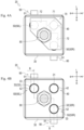
- FIG. 4A
- is a cross-sectional view taken along line A-A;
- FIG. 4B
- is a view in which a coupling member illustrated in
Fig. 4A is omitted; - FIG. 5
- is a cross-sectional view taken along line B-B;
- FIG. 6A
- is a side view illustrating a moving pin;
- FIG. 6B
- is a cross-sectional view taken along line C-C; and
- FIG. 7
- is a plan view illustrating a second through hole and a moving pin according to a modification.
- In the following description, directions indicated by arrows U, D, F, B, L, and R in the drawings are defined as an upward direction, a downward direction, a forward direction, a backward direction, a left direction, and a right direction, respectively.
- Hereinafter, a tractor 1 according to an embodiment of the disclosure will be described with reference to
Fig. 1 . - The tractor 1 mainly includes a machine body frame 2, an
engine 3, a transmission case 4,front wheels 5,rear wheels 6, abonnet 7, acabin 8, asteering wheel 9, aseat 10, and afront loader 11. - The machine body frame 2 is a frame-shaped member formed by appropriately combining a plurality of panel members. The machine body frame 2 is formed in a substantially rectangular shape in plan view. The machine body frame 2 is disposed with its longitudinal direction oriented in a front-rear direction. The
engine 3 is fixed to a rear portion of the machine body frame 2. The transmission case 4 is fixed to a rear portion of theengine 3. A front portion of the machine body frame 2 is supported by the pair of left and rightfront wheels 5 through a front axle mechanism (not illustrated). A rear portion of the transmission case 4 is supported by the pair of left and rightrear wheels 6 through a rear axle mechanism (not illustrated). Theengine 3 is covered with thebonnet 7. - Power of the
engine 3 can be transmitted to thefront wheels 5 through the front axle mechanism and can be transmitted to therear wheels 6 through the rear axle mechanism after being shifted by a transmission device (not illustrated) accommodated in the transmission case 4. Thefront wheels 5 and therear wheels 6 are rotationally driven by the power of theengine 3, and the tractor 1 can travel. - The
cabin 8 is provided behind theengine 3. Asteering wheel 9 and various operation tools for adjusting a turning angle of thefront wheels 5 are disposed in a front portion of thecabin 8. Theseat 10 on which a driver sits is disposed substantially at a center of thecabin 8. Furthermore, anoperation mechanism 20 for operating thefront loader 11 is provided near theseat 10. - The
front loader 11 is attached to a front portion of the tractor 1. Thefront loader 11 includes aboom 12, abucket 13, aboom cylinder 14, abucket cylinder 15, acontrol valve 16, and the like. - The
boom 12 is disposed so as to extend forward and downward. Thebucket 13 is detachably coupled to a front end portion of theboom 12. Thecontrol valve 16 is configured to be able to feed hydraulic pressure to theboom cylinder 14 and thebucket cylinder 15. Thecontrol valve 16 is disposed below thecabin 8. Theboom 12 can be rotated with respect to a vehicle body by expansion and contraction of theboom cylinder 14 by the hydraulic pressure from thecontrol valve 16. Thebucket 13 can rotate with respect to theboom 12 when thebucket cylinder 15 is expanded and contracted by the hydraulic pressure from thecontrol valve 16. As described above, the work of transporting earth and sand, and the like can be carried out while appropriately rotating theboom 12 and thebucket 13. - Hereinafter, the
operation mechanism 20 of thefront loader 11 will be described with reference toFigs. 2 to 6A and6B . - The
operation mechanism 20 is for operating thefront loader 11 in accordance with an operation of an operator. As illustrated inFig. 2 , theoperation mechanism 20 includes asupport member 30, a fixingpin 40, a movingpin 50, acable 60, acoupling member 70, anoperation lever 80, and arestriction mechanism 90. Note thatFigs. 2 to 5 illustrate theoperation mechanism 20 in a case where theoperation lever 80 is located at a neutral position. - The
support member 30 illustrated inFigs. 2 ,3 , and4B is a member for supporting various members (the fixingpin 40 and the like) of theoperation mechanism 20. Thesupport member 30 is formed in a substantially rectangular parallelepiped shape. Thesupport member 30 is provided in thecabin 8. As illustrated inFigs. 3 and4B , thesupport member 30 includes a first throughhole 31, a second throughhole 32, and acommunication hole 33. - The first through
hole 31 and the second throughhole 32 vertically penetrate thesupport member 30. The first throughhole 31 and the second throughhole 32 are formed in a substantially circular shape in plan view. The first throughhole 31 is formed in a left front portion of thesupport member 30. The second throughhole 32 is formed in each of a left rear portion and a right front portion of thesupport member 30. Hereinafter, the second throughhole 32 formed in the left rear portion of thesupport member 30 is referred to as a "left second throughhole 32L". Furthermore, the second throughhole 32 formed in the right front portion of thesupport member 30 is referred to as a "right second throughhole 32R". - The
communication hole 33 illustrated inFigs. 4B and5 is a hole that allows the second throughhole 32 and an outer surface of thesupport member 30 to communicate with each other. Onecommunication hole 33 is formed for one second throughhole 32. Thecommunication hole 33 is formed to extend in the left-right direction. Thecommunication hole 33 is formed in a substantially circular shape in side view. Thecommunication hole 33 is formed so as to communicate the left second throughhole 32L with a left side surface of thesupport member 30. Furthermore, thecommunication hole 33 is formed to communicate the right second throughhole 32R with a right side surface of thesupport member 30. A female screw portion is formed (not illustrated) on an inner peripheral surface of each of the communication holes 33. - The fixing
pin 40 illustrated inFigs. 3 ,4A and 4B is a member fixed to thesupport member 30. The fixingpin 40 includes acolumnar portion 41, aspherical portion 42, and aconnection portion 43. Thecolumnar portion 41 is a columnar portion whose axial direction is oriented in the vertical direction. Thecolumnar portion 41 is fixed to the first throughhole 31. Thespherical portion 42 is a portion formed in a substantially spherical shape. Thespherical portion 42 is formed above thecolumnar portion 41. Theconnection portion 43 is a portion that connects thecolumnar portion 41 and thespherical portion 42. Thespherical portion 42 and theconnection portion 43 are located above thesupport member 30. - The moving
pin 50 illustrated inFigs. 4B and5 is a member relatively movable in the vertical direction with respect to thesupport member 30. The movingpin 50 is provided in each of the left and right second throughholes pin 50 provided in the left second throughhole 32L is referred to as a "left movingpin 50L". Furthermore, the movingpin 50 provided in the right second throughhole 32R is referred to as a "right movingpin 50R". Hereinafter, the configuration of the movingpin 50 will be described by taking theright moving pin 50R as an example. The movingpin 50 includes acolumnar portion 51, aspherical portion 52, and aconnection portion 53. - The
columnar portion 51 is a columnar portion whose axial direction is oriented in the vertical direction. An outer diameter of thecolumnar portion 51 is smaller than an inner diameter of the second throughhole 32. Thecolumnar portion 51 is accommodated in the second throughhole 32. As illustrated inFigs. 5 and6A , thecolumnar portion 51 includes afirst recess 51a and asecond recess 51b. - The
first recess 51a and thesecond recess 51b are formed to be recessed leftward (toward a center of the columnar portion 51) on an outer peripheral surface of thecolumnar portion 51. Thefirst recess 51a is formed in a substantially hemispherical shape along aball 92 of therestriction mechanism 90 described later. Thefirst recess 51a is formed in a lower portion of thecolumnar portion 51. - The
second recess 51b is formed so as to extend in the vertical direction (moving direction of the moving pin 50) from thefirst recess 51a. A depth of thesecond recess 51b is shallower than that of thefirst recess 51a. Note that a magnitude relationship between the depths of thefirst recess 51a and thesecond recess 51b is not limited to the present embodiment. For example, thefirst recess 51a and thesecond recess 51b may have the same depth. Thesecond recess 51b is formed on each of an upper side and a lower side of thefirst recess 51a. As illustrated inFig. 6A , thesecond recess 51b on the upper side includes asharp portion 51c and astraight portion 51d. - The
sharp portion 51c is a portion formed in a tapered shape in which a lateral width decreases toward thefirst recess 51a. Thestraight portion 51d is a portion extending in the vertical direction with a constant lateral width. Thestraight portion 51d is formed in a substantially arc shape in plan cross-sectional view (seeFig. 6B ). Thestraight portion 51d is formed to extend from thesharp portion 51c to an upper end portion of thecolumnar portion 51. - The
second recess 51b on the lower side includes only thesharp portion 51c of the above-describedsharp portion 51c andstraight portion 51d. Note that thesecond recess 51b on the lower side may include thestraight portion 51d according to an amount of movement of the movingpin 50, a vertical position of thefirst recess 51a, and the like. - The
spherical portion 52 illustrated inFigs. 5 and6A is formed above thecolumnar portion 51. Thespherical portion 52 is formed in the same shape as thespherical portion 42 of the fixingpin 40. - The
connection portion 53 is a portion that connects thecolumnar portion 51 and thespherical portion 52. Theconnection portion 53 is formed in a substantially columnar shape. Aflat portion 53a is formed in theconnection portion 53. Theflat portion 53a is disposed above thefirst recess 51a and thesecond recess 51b so as to face rightward. Theflat portion 53a is located above the second throughhole 32. - The
cable 60 illustrated inFig. 5 is for transmitting an operation force of theoperation lever 80 to thecontrol valve 16. Thecable 60 is formed in a longitudinal shape (linear shape) and has flexibility. Thecable 60 connects the left and right movingpins control valve 16. Thecable 60 includes anouter cable 61 and aninner cable 62. - The
outer cable 61 is formed so as to cover theinner cable 62. One end portion of theouter cable 61 is coupled to thesupport member 30. The other end portion of theouter cable 61 is fixed to the vehicle body in the vicinity of thecontrol valve 16 illustrated inFig. 1 . - One end portion of the
inner cable 62 illustrated inFig. 5 protrudes upward from the one end portion of theouter cable 61 and is coupled to the movingpin 50. The other end portion of theinner cable 62 protrudes from the other end portion of theouter cable 61 and is coupled to the spool of thecontrol valve 16 illustrated inFig. 1 . More specifically, the other end portion of theouter cable 61 is coupled to the spool by inserting a pin into a hole portion formed in the spool. - The
coupling member 70 illustrated inFigs. 2 ,3 , and4A is a member to which theoperation lever 80 is coupled. Thecoupling member 70 is formed in a plate shape with a plate surface oriented in the vertical direction. Thecoupling member 70 is disposed above thesupport member 30. Thecoupling member 70 includes afirst notch 71 and asecond notch 72. - The
first notch 71 illustrated inFigs. 3 and4A has a substantially semicircular cross-sectional shape with an opening facing downward, and is formed so as to extend from a left front end of thecoupling member 70 to the right rear. Thefirst notch 71 is formed in a left front portion of the coupling member 70 (above the first through hole 31). Thespherical portion 42 of the fixingpin 40 is accommodated in thefirst notch 71. - The
second notch 72 is formed in a left rear portion (above the left second through hole 32) and a right front portion (above the right second through hole 32) of thecoupling member 70. Thesecond notch 72 at the left rear portion has a substantially semicircular cross-sectional shape with an opening facing downward, and is formed to extend forward from a rear side surface of thecoupling member 70. Thespherical portion 52 of the left movingpin 50L is accommodated in thesecond notch 72 at the left rear portion. Thesecond notch 72 at the right front portion has a substantially semicircular cross-sectional shape with an opening facing downward, and is formed to extend leftward from a right side surface of thecoupling member 70. Thespherical portion 52 of theright moving pin 50R is accommodated in thesecond notch 72 at the right front portion. - The
operation lever 80 illustrated inFig. 2 is a member that can be operated by an operator. Theoperation lever 80 is formed by appropriately bending a rod-like member. A lower end portion of theoperation lever 80 is coupled to thecoupling member 70. The lower end portion of theoperation lever 80 is located at a position not overlapping with the fixingpin 40 and the movingpin 50 in plan view (seeFigs. 4A and 4B ). - As illustrated in
Fig. 2 , theoperation lever 80 is configured to be operable in the left-right direction and the front-rear direction from the neutral position. In a case where theoperation lever 80 is moved in the left-right direction, thecoupling member 70 rocks left and right with the fixingpin 40 as a fulcrum. With this rocking, the right front portion of thecoupling member 70 rocks up and down, and theright moving pin 50R accommodated in thesecond notch 72 of the right front portion is moved in the vertical direction. Thus, as illustrated inFig. 5 , theright moving pin 50R slides in the vertical direction with respect to the right second throughhole 32R of thesupport member 30. Along with the sliding, the cable 60 (inner cable 62) coupled to theright moving pin 50R is moved in the vertical direction, the spool of thecontrol valve 16 is displaced, and thebucket cylinder 15 is controlled. As a result, the operator can operate thebucket 13 according to the operation of theoperation lever 80 in the left-right direction. - Furthermore, in a case where the
operation lever 80 illustrated inFig. 2 is rocked in the front-rear direction, thecoupling member 70 rocks back and forth with the fixingpin 40 as a fulcrum. With this rocking, the left rear portion of thecoupling member 70 rocks up and down, and the left movingpin 50L accommodated in thesecond notch 72 of the left rear portion is moved in the vertical direction. Thus, as illustrated inFig. 5 , the left movingpin 50L slides in the vertical direction with respect to the left second throughhole 32L of thesupport member 30. Along with the sliding, the cable 60 (inner cable 62) coupled to the left movingpin 50L is moved in the vertical direction, the spool of thecontrol valve 16 is displaced, and theboom cylinder 14 is controlled. As a result, the operator can operate theboom 12 according to the operation of theoperation lever 80 in the front-rear direction. - Here, there is a possibility that the spool is not displaced (only the
cable 60 moves) until theoperation lever 80 is operated by a predetermined amount or more from the vicinity of the neutral position due to an influence of a gap generated between theouter cable 61 and theinner cable 62, a gap generated at a coupling portion between the spool and the cable 60 (between the hole portion of the spool and the pin), and the like. In a case where there is an operation range (backlash) in which the spool is not displaced, there is a possibility that theoperation lever 80 moves (backlash) near the center position unintentionally by the operator due to vibration or the like during traveling of the tractor 1. - The
restriction mechanism 90 illustrated inFigs. 4A, 4B and5 restricts the movement of the movingpin 50 located at the neutral position to reduce the influence of the above-described backlash (backlash during traveling). Therestriction mechanism 90 is provided on thesupport member 30. Onerestriction mechanism 90 is provided for one movingpin 50. Hereinafter, the configuration of therestriction mechanism 90 will be described by taking as an example therestriction mechanism 90 that restricts the movement of theright moving pin 50R. Therestriction mechanism 90 includes anaccommodation member 91, aball 92, and aspring 93. - The
accommodation member 91 illustrated inFig. 5 is a member for accommodating theball 92 and thespring 93. Theaccommodation member 91 is formed in a bottomed substantially cylindrical shape. Theaccommodation member 91 is disposed with an axial direction oriented in the left-right direction. Furthermore, theaccommodation member 91 is disposed such that an opening faces the left side (second through hole 32). A male screw portion is formed on an outer peripheral surface of the accommodation member 91 (not illustrated). Theaccommodation member 91 is attached to thesupport member 30 by being screwed into thecommunication hole 33. - The
ball 92 is disposed in an opening of the support member 30 (an end portion on a side of the second through hole 32). A part of theball 92 protrudes from the opening. Theball 92 abuts on (engages with) thefirst recess 51a of the movingpin 50 in a state where theoperation lever 80 is located at the neutral position (state illustrated inFig. 5 ). - The
spring 93 biases theball 92 leftward (toward the moving pin 50). Thespring 93 is accommodated in theaccommodation member 91 and is disposed between a bottom (right end portion) of theaccommodation member 91 and theball 92. Note that, although thespring 93 is configured by a compression coil spring in the present embodiment, a biasing member that biases theball 92 is not limited to the compression coil spring, and may be another type of spring or an elastic body such as resin. - According to the
restriction mechanism 90, in a case where theright moving pin 50R tries to move in the vertical direction in a state where theoperation lever 80 is located at the neutral position, theball 92 tries to climb over thefirst recess 51a. At this time, theball 92 is pressed against thefirst recess 51a by thespring 93, and the movement of the movingpin 50R in the vertical direction is restricted. Thus, theoperation lever 80 can be prevented from backlashing in the left-right direction near the neutral position due to vibration or the like during traveling of the tractor 1. - In particular, in the present embodiment, not only the
right moving pin 50R but also the movement of the left movingpin 50L is restricted by therestriction mechanism 90. As a result, it is possible to suppress backlash of theoperation lever 80 in the front-rear direction near the neutral position, so that the influence of the backlash can be effectively reduced. - Furthermore, when a predetermined operation load or more is applied to the
operation lever 80 located at the neutral position, the operator can move the movingpin 50 up and down against a biasing force of thespring 93. In a case where theball 92 climbs over thefirst recess 51a along with the movement, thesecond recess 51b abuts on theball 92. In a case where theoperation lever 80 is further operated in this state, the movingpin 50 moves in the vertical direction while theball 92 is guided by thesecond recess 51b. As described above, in the present embodiment, even after theball 92 climbs over thefirst recess 51a, theball 92 is continuously released toward the second throughhole 32 by the other recess (second recess 51b). - As a result, the biasing force of the
spring 93 can be made relatively small, so that it is possible to suppress an increase in the operation load after theoperation lever 80 is moved from the neutral position, and it is possible to suppress a decrease in operability. - Furthermore, the
accommodation member 91 of the present embodiment is screwed into thecommunication hole 33. According to this configuration, the biasing force of thespring 93 can be easily adjusted by adjusting a screwing amount of theaccommodation member 91 into thecommunication hole 33. - Furthermore, in the present embodiment, the
flat portion 53a of the movingpin 50 is disposed between thesupport member 30 and the coupling member 70 (seeFig. 3 ). With this configuration, since theflat portion 53a can be visually recognized from the outside, circumferential positions of thefirst recess 51a and thesecond recess 51b can be easily grasped using theflat portion 53a as a mark. - As described above, the
operation mechanism 20 of thefront loader 11 according to the present embodiment includes theoperation lever 80, the moving pin 50 (moving member) that is movable in a predetermined direction (vertical direction) according to the operation of theoperation lever 80 and is connected to thecontrol valve 16, and therestriction mechanism 90 that restricts the movement of the movingpin 50 in a state where theoperation lever 80 is operated to the neutral position. - With this configuration, the influence of backlash of the
operation lever 80 can be reduced. - Furthermore, the
restriction mechanism 90 includes the ball 92 (abutment member) capable of abutting on the surface of the movingpin 50, and the spring 93 (biasing member) that biases theball 92 toward the moving pin 50 (seeFig. 5 ). - With this configuration, the influence of backlash of the
operation lever 80 can be reduced with a simple configuration. - Furthermore, the moving
pin 50 includes thefirst recess 51a engageable with theball 92 in a state where theoperation lever 80 is operated to the neutral position (seeFig. 5 ). - With this configuration, the influence of backlash of the
operation lever 80 can be effectively reduced. - Furthermore, the moving
pin 50 includes thesecond recess 51b that is formed to extend along the moving direction (vertical direction) of the movingpin 50 and guides the ball 92 (seeFig. 5 ). - With this configuration, it is possible to suppress an increase in the operation load of the
operation lever 80 due to the provision of therestriction mechanism 90. - Furthermore, the
support member 30 in which the second through hole 32 (accommodation portion) that accommodates the movingpin 50 is formed is further provided, and therestriction mechanism 90 is provided in thecommunication hole 33 that communicates the outer surface of thesupport member 30 and the second through hole 32 (seeFig. 5 ). - With this configuration, the
restriction mechanism 90 can be easily provided from the outside of thesupport member 30. - Furthermore, the moving
pin 50 includes a boom moving member (the left movingpin 50L) that controls the operation of theboom 12 of thefront loader 11 and a bucket moving member (theright moving pin 50R) that controls the operation of thebucket 13 of thefront loader 11. - With this configuration, it is possible to reduce the influence of backlash of the
operation lever 80 in the two operation directions (the directions in which theboom 12 and thebucket 13 are operated). - Furthermore, as described above, the tractor 1 (working vehicle) according to the present embodiment includes the
operation mechanism 20 of thefront loader 11. - With this configuration, the influence of backlash of the
operation lever 80 can be reduced. - Note that the moving
pin 50 according to the present embodiment is an embodiment of the moving member according to the disclosure. - Furthermore, the
ball 92 according to the present embodiment is an embodiment of the abutment member according to the disclosure. - Furthermore, the
spring 93 according to the present embodiment is an embodiment of the biasing member according to the disclosure. - Furthermore, the second through
hole 32 according to the present embodiment is an embodiment of the accommodation portion according to the disclosure. - Furthermore, the tractor 1 according to the present embodiment is an embodiment of a working vehicle according to the disclosure.
- Although the embodiments of the disclosure have been described above, the disclosure is not limited to the above configurations, and various modifications can be made within the scope of the invention described in the claims.
- For example, the working vehicle according to the present embodiment is the tractor 1, but the type of the working vehicle is not limited thereto. The working vehicle may be another agricultural vehicle, a construction vehicle, an industrial vehicle, or the like.
- Furthermore, in the present embodiment, the movement of the left and right moving
pins restriction mechanism 90 according to the disclosure may restrict the movement of at least one movingpin 50. - Furthermore, the configuration of the
restriction mechanism 90 is not limited to the present embodiment as long as the movement of the movingpin 50 can be restricted. For example, a member having a shape different from the spherical shape (ball 92) can be brought into contact with the movingpin 50. - Furthermore, although the
first recess 51a is formed in a substantially hemispherical shape, the shape of thefirst recess 51a can be appropriately changed according to the shape or the like of the abutment member to abut on the movingpin 50. Furthermore, thesecond recess 51b is formed in a substantially arc shape in plan cross-sectional view, but the shape of thesecond recess 51b can be appropriately changed according to the shape or the like of the abutment member. - Furthermore, although the moving
pin 50 moves in the vertical direction according to the operation of theoperation lever 80, this is an example, and the moving direction of the movingpin 50 can be arbitrarily changed. - Furthermore, although the second through
hole 32 and the moving pin 50 (columnar portion 51) are formed in a circular shape in plan view, this is an example, and the second through hole and the moving pin may be formed in a shape different from a circle in plan view. For example, as illustrated inFig. 7 , the second throughhole 32 and the movingpin 50 may be formed in a shape in which a part of a circle is cut out in plan view. InFig. 7 ,flat portions hole 32 and the movingpin 50. According to this configuration, when the movingpin 50 tries to rotate about its axis, theflat portions pin 50 can be restricted. - As described above, the moving
pin 50 includes theflat portion 51e (rotation restriction portion) that restricts the rotation about the axis parallel to the moving direction (vertical direction) of the movingpin 50. - With such a configuration, it is possible to easily position the moving
pin 50 with respect to the support member 30 (accommodation portion). As a result, the moving pin 50 (columnar portion 51) can be quickly accommodated in thesupport member 30. - Note that the
flat portion 51e illustrated inFig. 7 is an embodiment of the rotation restriction portion according to the disclosure. - The rotation restriction portion is not limited to the
flat portion 51e as long as the rotation restriction portion can restrict the rotation of the movingpin 50. For example, the rotation restriction portion may be an uneven portion or the like formed on thecolumnar portion 51.
Claims (8)
- An operation mechanism (20) of a front loader (11), the operation mechanism (20) comprising:- an operation lever (80);- a moving member (50) movable in a predetermined direction according to an operation of the operation lever (80) and connected to a control valve (16); and- a restriction mechanism (90) configured to restrict movement of the moving member (50) in a state where the operation lever (80) is operated to a neutral position.
- The operation mechanism (20) of a front loader (11) according to claim 1, wherein
the restriction mechanism (90) includes:- an abutment member (92) capable of abutting on a surface of the moving member (50), and- a biasing member (93) configured to bias the abutment member (92) toward the moving member (50). - The operation mechanism (20) of a front loader (11) according to claim 2, wherein the moving member (50) includes a first recess (51a) engageable with the abutment member (92) in a state where the operation lever (80) is operated to the neutral position.
- The operation mechanism (20) of a front loader (11) according to claim 3, wherein the moving member (50) includes a second recess (51b) formed to extend along a moving direction of the moving member (50) and configured to guide the abutment member (92).
- The operation mechanism (20) of a front loader (11) according to claim 2, further comprising a support member (30) in which an accommodation portion (32) that accommodates the moving member (50) is formed, wherein the restriction mechanism (90) is provided in a communication hole (33) that communicates an outer surface of the support member (30) and the accommodation portion (32).
- The operation mechanism (20) of a front loader (11) according to claim 5, wherein the moving member (50) includes a rotation restriction portion (51e) configured to restrict rotation about an axis parallel to a moving direction of the moving member (50).
- The operation mechanism (20) of a front loader (11) according to claim 1, wherein
the moving member (50) includes:- a boom moving member (50L) configured to control an operation of a boom (12) of the front loader (11), and- a bucket moving member (50R) configured to control an operation of a bucket (13) of the front loader (11). - A working vehicle (1) comprising the operation mechanism (20) of a front loader (11) according to any one of claims 1 to 7.
Applications Claiming Priority (1)
| Application Number | Priority Date | Filing Date | Title |
|---|---|---|---|
| JP2023127440A JP2025023373A (en) | 2023-08-04 | 2023-08-04 | Front loader operation mechanism and work vehicle |
Publications (1)
| Publication Number | Publication Date |
|---|---|
| EP4509662A1 true EP4509662A1 (en) | 2025-02-19 |
Family
ID=91829508
Family Applications (1)
| Application Number | Title | Priority Date | Filing Date |
|---|---|---|---|
| EP24186402.4A Pending EP4509662A1 (en) | 2023-08-04 | 2024-07-04 | Operation mechanism of front loader and working vehicle |
Country Status (3)
| Country | Link |
|---|---|
| US (1) | US12428810B2 (en) |
| EP (1) | EP4509662A1 (en) |
| JP (1) | JP2025023373A (en) |
Citations (4)
| Publication number | Priority date | Publication date | Assignee | Title |
|---|---|---|---|---|
| US4526055A (en) * | 1981-04-21 | 1985-07-02 | Massey-Ferguson Services N.V. | Lockable control lever arrangement |
| JP2004360331A (en) * | 2003-06-05 | 2004-12-24 | Kubota Corp | Working machine operating device |
| JP2017091061A (en) | 2015-11-05 | 2017-05-25 | ヤンマー株式会社 | Work vehicle |
| EP3670762A1 (en) * | 2018-12-20 | 2020-06-24 | Kubota Corporation | Operating mechanism of work vehicle |
Family Cites Families (6)
| Publication number | Priority date | Publication date | Assignee | Title |
|---|---|---|---|---|
| JP3997028B2 (en) * | 1999-02-09 | 2007-10-24 | ヤンマー株式会社 | Restriction mechanism for travel lever of reverse work vehicle |
| JP2005075619A (en) * | 2003-09-03 | 2005-03-24 | Furukawa Co Ltd | Operation lever safety device |
| JP2007172231A (en) * | 2005-12-21 | 2007-07-05 | Toyota Industries Corp | Control lever device |
| JP5368752B2 (en) * | 2008-09-02 | 2013-12-18 | ヤンマー株式会社 | Hydraulic circuit of work vehicle |
| JP6827916B2 (en) * | 2017-12-27 | 2021-02-10 | 株式会社クボタ | Lever device and work machine equipped with it |
| EP4361357A4 (en) * | 2021-06-24 | 2025-07-23 | Kubota Kk | LEVER DEVICE AND CONSTRUCTION MACHINE |
-
2023
- 2023-08-04 JP JP2023127440A patent/JP2025023373A/en active Pending
-
2024
- 2024-06-11 US US18/739,943 patent/US12428810B2/en active Active
- 2024-07-04 EP EP24186402.4A patent/EP4509662A1/en active Pending
Patent Citations (4)
| Publication number | Priority date | Publication date | Assignee | Title |
|---|---|---|---|---|
| US4526055A (en) * | 1981-04-21 | 1985-07-02 | Massey-Ferguson Services N.V. | Lockable control lever arrangement |
| JP2004360331A (en) * | 2003-06-05 | 2004-12-24 | Kubota Corp | Working machine operating device |
| JP2017091061A (en) | 2015-11-05 | 2017-05-25 | ヤンマー株式会社 | Work vehicle |
| EP3670762A1 (en) * | 2018-12-20 | 2020-06-24 | Kubota Corporation | Operating mechanism of work vehicle |
Also Published As
| Publication number | Publication date |
|---|---|
| JP2025023373A (en) | 2025-02-17 |
| US12428810B2 (en) | 2025-09-30 |
| US20250043538A1 (en) | 2025-02-06 |
Similar Documents
| Publication | Publication Date | Title |
|---|---|---|
| US8434562B2 (en) | Ripper operating device | |
| CN108698633A (en) | Working truck | |
| EP3845434B1 (en) | Traveling vehicle | |
| US11878732B2 (en) | Work vehicle | |
| US12428810B2 (en) | Operation mechanism of front loader and working vehicle | |
| EP3705380B1 (en) | Work vehicle | |
| US12012788B2 (en) | Work vehicle | |
| US11447194B2 (en) | Operating mechanism of work vehicle | |
| US8468905B2 (en) | Operating device for control valve | |
| JP5771119B2 (en) | Work vehicle | |
| US20250251039A1 (en) | Working vehicle | |
| USH1851H (en) | Motor grader having dual steering mechanisms | |
| JP5069669B2 (en) | Work vehicle | |
| US10969003B2 (en) | Operation device and work vehicle | |
| JP7806640B2 (en) | Work vehicles | |
| EP3718808B1 (en) | Operation mechanism of work vehicle and work vehicle | |
| JP6775448B2 (en) | Work platform | |
| JP7842706B2 (en) | Work vehicle | |
| US20220205219A1 (en) | Work vehicle | |
| JP2024096544A (en) | Work vehicle | |
| JP6475137B2 (en) | Operating device | |
| JP6625027B2 (en) | Backhoe device and tractor backhoe | |
| JP7187360B2 (en) | Operating device and work vehicle | |
| KR101063320B1 (en) | Apparatus for controlling hitch of tractor | |
| KR20230170572A (en) | Agricultural tractor |
Legal Events
| Date | Code | Title | Description |
|---|---|---|---|
| PUAI | Public reference made under article 153(3) epc to a published international application that has entered the european phase |
Free format text: ORIGINAL CODE: 0009012 |
|
| STAA | Information on the status of an ep patent application or granted ep patent |
Free format text: STATUS: THE APPLICATION HAS BEEN PUBLISHED |
|
| AK | Designated contracting states |
Kind code of ref document: A1 Designated state(s): AL AT BE BG CH CY CZ DE DK EE ES FI FR GB GR HR HU IE IS IT LI LT LU LV MC ME MK MT NL NO PL PT RO RS SE SI SK SM TR |
|
| STAA | Information on the status of an ep patent application or granted ep patent |
Free format text: STATUS: REQUEST FOR EXAMINATION WAS MADE |
|
| 17P | Request for examination filed |
Effective date: 20250722 |