EP4509640A1 - Thermal protection methods using barrier coatings with strain tolerance grooves - Google Patents
Thermal protection methods using barrier coatings with strain tolerance grooves Download PDFInfo
- Publication number
- EP4509640A1 EP4509640A1 EP24189967.3A EP24189967A EP4509640A1 EP 4509640 A1 EP4509640 A1 EP 4509640A1 EP 24189967 A EP24189967 A EP 24189967A EP 4509640 A1 EP4509640 A1 EP 4509640A1
- Authority
- EP
- European Patent Office
- Prior art keywords
- grooves
- component
- thermal
- barrier coating
- insulating layer
- Prior art date
- Legal status (The legal status is an assumption and is not a legal conclusion. Google has not performed a legal analysis and makes no representation as to the accuracy of the status listed.)
- Pending
Links
Images




Classifications
-
- C—CHEMISTRY; METALLURGY
- C23—COATING METALLIC MATERIAL; COATING MATERIAL WITH METALLIC MATERIAL; CHEMICAL SURFACE TREATMENT; DIFFUSION TREATMENT OF METALLIC MATERIAL; COATING BY VACUUM EVAPORATION, BY SPUTTERING, BY ION IMPLANTATION OR BY CHEMICAL VAPOUR DEPOSITION, IN GENERAL; INHIBITING CORROSION OF METALLIC MATERIAL OR INCRUSTATION IN GENERAL
- C23C—COATING METALLIC MATERIAL; COATING MATERIAL WITH METALLIC MATERIAL; SURFACE TREATMENT OF METALLIC MATERIAL BY DIFFUSION INTO THE SURFACE, BY CHEMICAL CONVERSION OR SUBSTITUTION; COATING BY VACUUM EVAPORATION, BY SPUTTERING, BY ION IMPLANTATION OR BY CHEMICAL VAPOUR DEPOSITION, IN GENERAL
- C23C24/00—Coating starting from inorganic powder
- C23C24/02—Coating starting from inorganic powder by application of pressure only
- C23C24/04—Impact or kinetic deposition of particles
-
- C—CHEMISTRY; METALLURGY
- C23—COATING METALLIC MATERIAL; COATING MATERIAL WITH METALLIC MATERIAL; CHEMICAL SURFACE TREATMENT; DIFFUSION TREATMENT OF METALLIC MATERIAL; COATING BY VACUUM EVAPORATION, BY SPUTTERING, BY ION IMPLANTATION OR BY CHEMICAL VAPOUR DEPOSITION, IN GENERAL; INHIBITING CORROSION OF METALLIC MATERIAL OR INCRUSTATION IN GENERAL
- C23C—COATING METALLIC MATERIAL; COATING MATERIAL WITH METALLIC MATERIAL; SURFACE TREATMENT OF METALLIC MATERIAL BY DIFFUSION INTO THE SURFACE, BY CHEMICAL CONVERSION OR SUBSTITUTION; COATING BY VACUUM EVAPORATION, BY SPUTTERING, BY ION IMPLANTATION OR BY CHEMICAL VAPOUR DEPOSITION, IN GENERAL
- C23C28/00—Coating for obtaining at least two superposed coatings either by methods not provided for in a single one of groups C23C2/00 - C23C26/00 or by combinations of methods provided for in subclasses C23C and C25C or C25D
- C23C28/04—Coating for obtaining at least two superposed coatings either by methods not provided for in a single one of groups C23C2/00 - C23C26/00 or by combinations of methods provided for in subclasses C23C and C25C or C25D only coatings of inorganic non-metallic material
-
- F—MECHANICAL ENGINEERING; LIGHTING; HEATING; WEAPONS; BLASTING
- F01—MACHINES OR ENGINES IN GENERAL; ENGINE PLANTS IN GENERAL; STEAM ENGINES
- F01D—NON-POSITIVE DISPLACEMENT MACHINES OR ENGINES, e.g. STEAM TURBINES
- F01D5/00—Blades; Blade-carrying members; Heating, heat-insulating, cooling or antivibration means on the blades or the members
- F01D5/12—Blades
- F01D5/28—Selecting particular materials; Particular measures relating thereto; Measures against erosion or corrosion
- F01D5/288—Protective coatings for blades
-
- C—CHEMISTRY; METALLURGY
- C09—DYES; PAINTS; POLISHES; NATURAL RESINS; ADHESIVES; COMPOSITIONS NOT OTHERWISE PROVIDED FOR; APPLICATIONS OF MATERIALS NOT OTHERWISE PROVIDED FOR
- C09D—COATING COMPOSITIONS, e.g. PAINTS, VARNISHES OR LACQUERS; FILLING PASTES; CHEMICAL PAINT OR INK REMOVERS; INKS; CORRECTING FLUIDS; WOODSTAINS; PASTES OR SOLIDS FOR COLOURING OR PRINTING; USE OF MATERIALS THEREFOR
- C09D5/00—Coating compositions, e.g. paints, varnishes or lacquers, characterised by their physical nature or the effects produced; Filling pastes
- C09D5/18—Fireproof paints including high temperature resistant paints
-
- C—CHEMISTRY; METALLURGY
- C23—COATING METALLIC MATERIAL; COATING MATERIAL WITH METALLIC MATERIAL; CHEMICAL SURFACE TREATMENT; DIFFUSION TREATMENT OF METALLIC MATERIAL; COATING BY VACUUM EVAPORATION, BY SPUTTERING, BY ION IMPLANTATION OR BY CHEMICAL VAPOUR DEPOSITION, IN GENERAL; INHIBITING CORROSION OF METALLIC MATERIAL OR INCRUSTATION IN GENERAL
- C23C—COATING METALLIC MATERIAL; COATING MATERIAL WITH METALLIC MATERIAL; SURFACE TREATMENT OF METALLIC MATERIAL BY DIFFUSION INTO THE SURFACE, BY CHEMICAL CONVERSION OR SUBSTITUTION; COATING BY VACUUM EVAPORATION, BY SPUTTERING, BY ION IMPLANTATION OR BY CHEMICAL VAPOUR DEPOSITION, IN GENERAL
- C23C28/00—Coating for obtaining at least two superposed coatings either by methods not provided for in a single one of groups C23C2/00 - C23C26/00 or by combinations of methods provided for in subclasses C23C and C25C or C25D
- C23C28/30—Coatings combining at least one metallic layer and at least one inorganic non-metallic layer
-
- C—CHEMISTRY; METALLURGY
- C23—COATING METALLIC MATERIAL; COATING MATERIAL WITH METALLIC MATERIAL; CHEMICAL SURFACE TREATMENT; DIFFUSION TREATMENT OF METALLIC MATERIAL; COATING BY VACUUM EVAPORATION, BY SPUTTERING, BY ION IMPLANTATION OR BY CHEMICAL VAPOUR DEPOSITION, IN GENERAL; INHIBITING CORROSION OF METALLIC MATERIAL OR INCRUSTATION IN GENERAL
- C23C—COATING METALLIC MATERIAL; COATING MATERIAL WITH METALLIC MATERIAL; SURFACE TREATMENT OF METALLIC MATERIAL BY DIFFUSION INTO THE SURFACE, BY CHEMICAL CONVERSION OR SUBSTITUTION; COATING BY VACUUM EVAPORATION, BY SPUTTERING, BY ION IMPLANTATION OR BY CHEMICAL VAPOUR DEPOSITION, IN GENERAL
- C23C4/00—Coating by spraying the coating material in the molten state, e.g. by flame, plasma or electric discharge
- C23C4/18—After-treatment
-
- F—MECHANICAL ENGINEERING; LIGHTING; HEATING; WEAPONS; BLASTING
- F01—MACHINES OR ENGINES IN GENERAL; ENGINE PLANTS IN GENERAL; STEAM ENGINES
- F01D—NON-POSITIVE DISPLACEMENT MACHINES OR ENGINES, e.g. STEAM TURBINES
- F01D25/00—Component parts, details, or accessories, not provided for in, or of interest apart from, other groups
- F01D25/005—Selecting particular materials
-
- F—MECHANICAL ENGINEERING; LIGHTING; HEATING; WEAPONS; BLASTING
- F01—MACHINES OR ENGINES IN GENERAL; ENGINE PLANTS IN GENERAL; STEAM ENGINES
- F01D—NON-POSITIVE DISPLACEMENT MACHINES OR ENGINES, e.g. STEAM TURBINES
- F01D25/00—Component parts, details, or accessories, not provided for in, or of interest apart from, other groups
- F01D25/007—Preventing corrosion
-
- F—MECHANICAL ENGINEERING; LIGHTING; HEATING; WEAPONS; BLASTING
- F01—MACHINES OR ENGINES IN GENERAL; ENGINE PLANTS IN GENERAL; STEAM ENGINES
- F01D—NON-POSITIVE DISPLACEMENT MACHINES OR ENGINES, e.g. STEAM TURBINES
- F01D25/00—Component parts, details, or accessories, not provided for in, or of interest apart from, other groups
- F01D25/08—Cooling; Heating; Heat-insulation
-
- F—MECHANICAL ENGINEERING; LIGHTING; HEATING; WEAPONS; BLASTING
- F01—MACHINES OR ENGINES IN GENERAL; ENGINE PLANTS IN GENERAL; STEAM ENGINES
- F01D—NON-POSITIVE DISPLACEMENT MACHINES OR ENGINES, e.g. STEAM TURBINES
- F01D5/00—Blades; Blade-carrying members; Heating, heat-insulating, cooling or antivibration means on the blades or the members
- F01D5/12—Blades
- F01D5/28—Selecting particular materials; Particular measures relating thereto; Measures against erosion or corrosion
- F01D5/286—Particular treatment of blades, e.g. to increase durability or resistance against corrosion or erosion
-
- C—CHEMISTRY; METALLURGY
- C23—COATING METALLIC MATERIAL; COATING MATERIAL WITH METALLIC MATERIAL; CHEMICAL SURFACE TREATMENT; DIFFUSION TREATMENT OF METALLIC MATERIAL; COATING BY VACUUM EVAPORATION, BY SPUTTERING, BY ION IMPLANTATION OR BY CHEMICAL VAPOUR DEPOSITION, IN GENERAL; INHIBITING CORROSION OF METALLIC MATERIAL OR INCRUSTATION IN GENERAL
- C23C—COATING METALLIC MATERIAL; COATING MATERIAL WITH METALLIC MATERIAL; SURFACE TREATMENT OF METALLIC MATERIAL BY DIFFUSION INTO THE SURFACE, BY CHEMICAL CONVERSION OR SUBSTITUTION; COATING BY VACUUM EVAPORATION, BY SPUTTERING, BY ION IMPLANTATION OR BY CHEMICAL VAPOUR DEPOSITION, IN GENERAL
- C23C28/00—Coating for obtaining at least two superposed coatings either by methods not provided for in a single one of groups C23C2/00 - C23C26/00 or by combinations of methods provided for in subclasses C23C and C25C or C25D
- C23C28/30—Coatings combining at least one metallic layer and at least one inorganic non-metallic layer
- C23C28/32—Coatings combining at least one metallic layer and at least one inorganic non-metallic layer including at least one pure metallic layer
- C23C28/321—Coatings combining at least one metallic layer and at least one inorganic non-metallic layer including at least one pure metallic layer with at least one metal alloy layer
- C23C28/3215—Coatings combining at least one metallic layer and at least one inorganic non-metallic layer including at least one pure metallic layer with at least one metal alloy layer at least one MCrAlX layer
-
- C—CHEMISTRY; METALLURGY
- C23—COATING METALLIC MATERIAL; COATING MATERIAL WITH METALLIC MATERIAL; CHEMICAL SURFACE TREATMENT; DIFFUSION TREATMENT OF METALLIC MATERIAL; COATING BY VACUUM EVAPORATION, BY SPUTTERING, BY ION IMPLANTATION OR BY CHEMICAL VAPOUR DEPOSITION, IN GENERAL; INHIBITING CORROSION OF METALLIC MATERIAL OR INCRUSTATION IN GENERAL
- C23C—COATING METALLIC MATERIAL; COATING MATERIAL WITH METALLIC MATERIAL; SURFACE TREATMENT OF METALLIC MATERIAL BY DIFFUSION INTO THE SURFACE, BY CHEMICAL CONVERSION OR SUBSTITUTION; COATING BY VACUUM EVAPORATION, BY SPUTTERING, BY ION IMPLANTATION OR BY CHEMICAL VAPOUR DEPOSITION, IN GENERAL
- C23C28/00—Coating for obtaining at least two superposed coatings either by methods not provided for in a single one of groups C23C2/00 - C23C26/00 or by combinations of methods provided for in subclasses C23C and C25C or C25D
- C23C28/30—Coatings combining at least one metallic layer and at least one inorganic non-metallic layer
- C23C28/34—Coatings combining at least one metallic layer and at least one inorganic non-metallic layer including at least one inorganic non-metallic material layer, e.g. metal carbide, nitride, boride, silicide layer and their mixtures, enamels, phosphates and sulphates
- C23C28/345—Coatings combining at least one metallic layer and at least one inorganic non-metallic layer including at least one inorganic non-metallic material layer, e.g. metal carbide, nitride, boride, silicide layer and their mixtures, enamels, phosphates and sulphates with at least one oxide layer
- C23C28/3455—Coatings combining at least one metallic layer and at least one inorganic non-metallic layer including at least one inorganic non-metallic material layer, e.g. metal carbide, nitride, boride, silicide layer and their mixtures, enamels, phosphates and sulphates with at least one oxide layer with a refractory ceramic layer, e.g. refractory metal oxide, ZrO2, rare earth oxides or a thermal barrier system comprising at least one refractory oxide layer
-
- C—CHEMISTRY; METALLURGY
- C23—COATING METALLIC MATERIAL; COATING MATERIAL WITH METALLIC MATERIAL; CHEMICAL SURFACE TREATMENT; DIFFUSION TREATMENT OF METALLIC MATERIAL; COATING BY VACUUM EVAPORATION, BY SPUTTERING, BY ION IMPLANTATION OR BY CHEMICAL VAPOUR DEPOSITION, IN GENERAL; INHIBITING CORROSION OF METALLIC MATERIAL OR INCRUSTATION IN GENERAL
- C23C—COATING METALLIC MATERIAL; COATING MATERIAL WITH METALLIC MATERIAL; SURFACE TREATMENT OF METALLIC MATERIAL BY DIFFUSION INTO THE SURFACE, BY CHEMICAL CONVERSION OR SUBSTITUTION; COATING BY VACUUM EVAPORATION, BY SPUTTERING, BY ION IMPLANTATION OR BY CHEMICAL VAPOUR DEPOSITION, IN GENERAL
- C23C4/00—Coating by spraying the coating material in the molten state, e.g. by flame, plasma or electric discharge
- C23C4/02—Pretreatment of the material to be coated, e.g. for coating on selected surface areas
-
- F—MECHANICAL ENGINEERING; LIGHTING; HEATING; WEAPONS; BLASTING
- F05—INDEXING SCHEMES RELATING TO ENGINES OR PUMPS IN VARIOUS SUBCLASSES OF CLASSES F01-F04
- F05D—INDEXING SCHEME FOR ASPECTS RELATING TO NON-POSITIVE-DISPLACEMENT MACHINES OR ENGINES, GAS-TURBINES OR JET-PROPULSION PLANTS
- F05D2230/00—Manufacture
- F05D2230/90—Coating; Surface treatment
-
- F—MECHANICAL ENGINEERING; LIGHTING; HEATING; WEAPONS; BLASTING
- F05—INDEXING SCHEMES RELATING TO ENGINES OR PUMPS IN VARIOUS SUBCLASSES OF CLASSES F01-F04
- F05D—INDEXING SCHEME FOR ASPECTS RELATING TO NON-POSITIVE-DISPLACEMENT MACHINES OR ENGINES, GAS-TURBINES OR JET-PROPULSION PLANTS
- F05D2300/00—Materials; Properties thereof
- F05D2300/60—Properties or characteristics given to material by treatment or manufacturing
- F05D2300/611—Coating
Definitions
- the present disclosure relates generally to thermal protection coatings for use with turbine engine components, and, more specifically, to methods for depositing material into strain tolerance grooves of a thermal barrier coating applied to turbine engine components.
- Turbine engines such as gas turbine engines and/or steam turbine engines, are widely used in industrial and power generation operations.
- Known turbine engines are subj ected to prolonged high temperatures, which over time may lead to deformation of the components of the turbine engines.
- at least some known turbine engine components include a thermal barrier coating.
- the thermal barrier coating on a turbine engine component includes one or more thermal insulating layers, as well as a metallic bond coat layer that extends directly across the base metal of the component.
- At least some known thermal barrier coatings are formed with strain tolerance grooves that extend across the turbine engine component.
- the presence of such grooves may result in a decreased thermal barrier coating thickness at the locations of each formed groove on the turbine engine component.
- oxidation and degradation of the metallic bond coat layer may be more likely to occur within or proximate to the strain tolerance grooves when exposed to the high operation temperatures at these locations. Accordingly, there exists a need for methods to deposit additional material into strain tolerance grooves of a thermal barrier coating to facilitate improving the overall thermal protection of the turbine engine components.
- a method of forming a component includes applying a thermal barrier coating to the component to facilitate decreasing heat transfer to the component, wherein the thermal barrier coating includes at least one thermal insulating layer and a metallic bond coat layer, wherein the at least one thermal insulating layer extends across the metallic bond coat layer and wherein the metallic bond coat layer is in contact with an outer surface of the component.
- the method also includes forming a plurality of grooves in the at least one thermal insulating layer of the thermal barrier coating to facilitate increasing a strain tolerance of the thermal barrier coating, wherein each of the plurality of grooves extends a depth into the at least one thermal insulating layer.
- the method further includes depositing a material within the plurality of grooves to facilitate increasing an amount of thermal protection of the metallic bond coat layer within those areas of the thermal barrier coating in which the plurality of grooves are formed.
- a method of fabricating a turbine engine component includes applying a thermal barrier coating to the component to facilitate decreasing heat transfer to the component, wherein the thermal barrier coating includes at least one thermal insulating layer and a metallic bond coat layer, wherein the at least one thermal insulating layer extends across the metallic bond coat layer and wherein the metallic bond coat layer is in contact with an outer surface of the component.
- the method also includes forming a plurality of grooves in the at least one thermal insulating layer of the applied thermal barrier coating to facilitate increasing a strain tolerance of the thermal barrier coating, wherein each of the plurality of grooves extends into a depth into the at least one thermal insulating layer to a groove bottom along a line perpendicular to the metallic bond coat layer.
- the method further includes depositing a material within the plurality of grooves to facilitate increasing an amount of thermal protection of the metallic bond coat layer that is proximate to the line of extension of each of the plurality of grooves.
- the embodiments described herein relate to methods for use in depositing material into strain tolerance grooves of a thermal barrier coating to facilitate improving the thermal protection of the turbine engine components.
- the methods described herein facilitate the thermal protection of turbine engine components.
- the advantages of the methods described herein include, at least: (i) improved thermal protection of a turbine engine component due to a thermal barrier coating protecting the component from heat damage; (ii) improved strain tolerance of the thermal barrier coating on the turbine engine component due to the grooves in the thermal barrier coating; and (iii) improved thermal protection of the turbine engine component due to the material deposited into the strain tolerance grooves of the thermal barrier coating to reduce the oxidation and degradation of a metallic bond coat layer of the thermal barrier coating proximate the strain tolerance grooves.
- approximating language such as “generally,” “substantially,” and “about,” as used herein indicates that the term so modified may apply to only an approximate degree, as would be recognized by one of ordinary skill in the art, rather than to an absolute or perfect degree. Accordingly, a value modified by a term or terms such as “about,” “approximately,” and “substantially” is not to be limited to the precise value specified. In at least some instances, the approximating language may correspond to the precision of an instrument for measuring the value. Additionally, unless otherwise indicated, the terms “first,” “second,” etc. are used herein merely as labels, and are not intended to impose ordinal, positional, or hierarchical requirements on the items to which these terms refer. Moreover, reference to, for example, a “second” item does not require or preclude the existence of, for example, a "first” or lower-numbered item or a “third” or higher-numbered item.
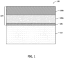
- FIG. 1 is a schematic illustration of an exemplary turbine engine component 100.
- the component 100 may be any of a variety of component types used in a variety of turbine engine applications, such as, for example, components utilized in high temperature applications.
- the component 100 may be a turbine blade, compressor blade, vane, nozzle, shroud, rotor, transition piece, and/or rotor casing.
- the component 100 may be any other component of a turbine engine.
- the component 100 includes a base metal 102 and a thermal barrier coating 104.
- the thermal barrier coating 104 may facilitate improving the thermal protection of the base metal 102 from exposure to high temperatures during use.
- the thermal barrier coating 104 includes a metallic bond coat layer 106 that contacts the base metal 102.
- the thermal barrier coating 104 may also include a plurality of thermal insulating layers 108.
- the thermal barrier coating 104 includes a first thermal insulating layer 108a and a second thermal insulating layer 108b.
- the thermal barrier coating 104 may include more or less than two thermal insulating layers 108.
- the thermal barrier coating 104 may include any material known in the art that facilitates the methods of thermal protection described herein.
- the first thermal insulating layer 108 and/or the second thermal insulating layer 108b may include one or more materials having one or more material properties that facilitate thermal protection of the metallic bond coat layer 106 of the thermal barrier coating 104 from the high operating temperatures of the component 100.
- the one or more materials included in the first thermal insulating layer 108 and/or the second thermal insulating layer 108b have the material property of a chemical composition.
- the chemical composition of the one or more materials included in the first thermal insulating layer 108 and/or the second thermal insulating layer 108b may include any chemical composition properties that facilitate the methods of thermal protection described herein. For example, adjustments of geometry (e.g., an element geometry and/or a composition geometry), a length, and/or a ratio (e.g., a molar ratio, a weight ratio, and/or a volume ratio) can adjust the size, shape, and properties of the one or more materials included in the first thermal insulating layer 108 and/or the second thermal insulating layer 108b. In some embodiments, the chemical composition may vary across the thermal insulating layers 108.
- geometry e.g., an element geometry and/or a composition geometry
- a length e.g., a length
- a ratio e.g., a molar ratio, a weight ratio, and/or a volume ratio
- the chemical composition may vary across the thermal insulating layers 108.
- the chemical composition of the first thermal insulating layer 108 may differ from the chemical composition of the second thermal insulating layer 108b.
- the chemical composition may be substantially the same for all thermal insulating layers 108.
- the chemical composition of the first thermal insulating layer 108 may be substantially the same as the chemical composition of the second thermal insulating layer 108b.
- FIG. 2 is a schematic illustration of an exemplary turbine engine component 200.
- the component 200 illustrated in FIG. 2 is similar to the component 100 (shown in FIG. 1 ), with the differences noted below, and as such, the same reference numbers are used to identify the same component in FIG. 2 as were used in FIG. 1 .
- the high temperatures in which the component 200 is used may strain the structure of the thermal barrier coating 104.
- the thermal barrier coating 104 may include vertical microcracks to facilitate increasing the strain tolerance of the thermal barrier coating 104.
- the thermal barrier coating 104 includes a plurality of grooves 202 that facilitate improving strain tolerance of the thermal barrier coating 104.
- the grooves 202 extend from an upper surface 112 of the thermal barrier coating 104 inwardly towards the base metal 102 of the component 200, such that a depth 114 of each of the grooves 202 extends to a bottom 116 of the grooves 202 defined within the second thermal insulating layer 108b of the thermal barrier coating 104.
- the thermal barrier coating 104 may include more or less than seven grooves 202, and as such, the illustration of a specific number of grooves 202 is not intended to be limiting.
- grooves 202 each having approximately the same depth 114, in alternative embodiments, at least one groove 202 may be formed with a different depth 114 than at least one other groove 202.
- grooves 202 are depicted as being substantially equi-spaced across component 200 and are substantially parallel to each other, in alternative embodiments, grooves 202 may be spaced in any orientation and/or may be aligned in any direction relative to each other that enables grooves 202 to facilitate improving the strain tolerance of thermal barrier coating 104.
- the shape of the grooves 202 is blunted or rounded at the bottom 116 to facilitate reducing cracking of the thermal barrier coating 104.
- the bottom 116 of each groove 202 may be formed with a radius or be semi-elliptical.
- grooves 202 may have any other shape, such as being generally triangular-shaped, that enables grooves 202 to facilitate improving the strain tolerance of thermal barrier coating 104 without increasing the likelihood of cracking forming.
- FIG. 3 is a schematic illustration of an exemplary turbine engine component 300.
- the component 300 illustrated in FIG. 3 is similar to the component 100 (shown in FIG. 1 ) and the component 200 (shown in FIG. 2 ), with the differences noted below, and as such, the same reference numbers are used in FIG. 3 to identify the same components as were used in FIGS. 1 and 2 .
- the thermal barrier coating 104 includes the plurality of grooves 202 to facilitate improved strain tolerance of the thermal barrier coating 104.
- each groove 202 extends from the upper surface 112 of the thermal barrier coating 104 inwardly towards the base metal 102 of the component 300, such that the depth 114 of each groove 202 is defined at its bottom 116 within the second thermal insulating layer 108b of the thermal barrier coating 104. Accordingly, the depth 114 of each groove 202 illustrated in FIG. 3 is deeper than the depth 114 of each groove 202 illustrated in FIG. 2 .
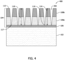
- FIG. 4 is a schematic illustration of an exemplary turbine engine component 400.
- the component 400 illustrated in FIG. 4 is similar to the component 100 (shown in FIG. 1 ), the component 200 (shown in FIG. 2 ), and the component 300 (shown in FIG. 3 ), with the differences noted below, and as such, the same reference numbers are used in FIG. 4 to identify the same components as were used in FIGS. 1-3 .
- the thermal barrier coating 104 includes the plurality of grooves 202 to facilitate improved strain tolerance of the thermal barrier coating 104.
- each groove 202 extends from the upper surface 112 of the thermal barrier coating 104 inwardly towards the base metal 102 of the component 300, such that the depth 114 of each groove 202 is defined at its bottom 116 at a junction 117 between the first thermal insulating layer 108 and the metallic bond coat layer 106. Accordingly, the depth 114 of each groove 202 illustrated in FIG. 4 is deeper than the depth 114 of each groove 202 illustrated in FIGS. 2 and 3 .
- a thickness 118 of the thermal barrier coating 104 is defined by the combined thicknesses of all of the individual thermal insulating layers 108 (e.g., the first thermal insulating layer 108a and the second thermal insulating layer 108b) as measured from the upper surface 112 of the thermal barrier coating 104 to the junction 117 defined between the first thermal insulating layer 108 and the metallic bond coat layer 106.
- the thickness 118 of the thermal barrier coating is defined as the combined thicknesses of the first thermal insulating layer 108 and the second thermal insulating layer 108b.
- each of the groove bottoms 116 is defined an intermediate distance 120 from the junction 117 defined between the first thermal insulating layer 108 and the metallic bond coat layer 106. As seen in FIGS. 2-4 , the intermediate thickness 120 is smaller than the overall thickness 118 of the thermal barrier coating 104. Thus, at the bottoms 116 of the grooves 202, the thermal barrier coating 104 provides less thermal protection between the high environmental operating temperatures of the component (e.g., the components 200, 300, 400) and the metallic bond coat layer 106.
- the increased proximity to the high operation temperatures e.g., because the metallic bond coat layer 106 has less thermal barrier coating 104 extending across it at each groove bottom 116
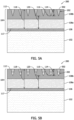
- FIGS. 5-7 are schematic illustrations of the turbine engine components (e.g., the components 200, 300, 400) including an insulating filler material 502 deposited within at least one of the plurality of grooves 202 of the thermal barrier coating 104.
- the insulating filler material 502 enhances the thermal protection provided at relative locations across the thermal barrier coating 104 in which less thermal barrier coating 104 extends across the metallic bond coat layer 106 (e.g., locations such as the bottom 116 of each groove 202).
- the insulating filler material 502 may be any material known in the art that facilitates enhancing thermal protection of the components as described herein.
- the insulating filler material 502 may have one or more material properties that facilitates enhancing thermal protection of the base metal 102 of the component (e.g., the components 200, 300, 400) and the metallic bond coat layer 106from the high environmental operating temperatures that each component may be exposed to.
- the insulating filler material 502 is variably selected to have intrinsic material properties of a desired chemical composition and porosity.
- the material selected may be chosen to have chemical composition properties that facilitate a desired level of thermal protection described herein.
- adjustments of geometry e.g., an element geometry and/or a composition geometry
- length, and/or ratio e.g., a molar ratio, a weight ratio, and/or a volume ratio
- ratio can enable the size, shape, and properties of the insulating filler material 502 to be variably selected and adjusted.
- the insulating filler material 502 may be selected to include any porosity properties that facilitate the methods of thermal protection described herein.
- the material can be variably selected to include desired particle density, particle size distribution, and/or particle shape properties.
- FIGS. 5A and 5B are schematic illustrations of the component 200, wherein the insulating filler material 502 substantially fills (shown in FIG. 5A ) and partially fills (shown in FIG. 5B ) each of the grooves 202.
- FIGS. 6A and 6B are schematic illustrations of the component 300, wherein the insulating filler material 502 substantially fills (shown in FIG. 6A ) and partially fills (shown in FIG. 6B ) each of the grooves 202.
- FIGS. 7A and 7B are schematic illustrations of the component 400, wherein the insulating filler material 502 substantially fills (shown in FIG. 7A ) and partially fills (shown in FIG. 7B ) each of the grooves 202.
- the grooves 202 may include any amount of insulating filler material 502, such that at least some grooves 202 may remain empty while other grooves 202 are completely filled with the insulating filler material 502. As such, the amount of insulating filler material 502 inserted within the grooves 202 is not intended to be limited by the amounts shown in FIGS. 5-7 .
- the amount of insulating filler material inserted into the grooves 202 may not be uniform across the component (e.g., component 200, 300, 400).
- FIGS. 5-7 illustrate a substantially uniform amount of insulating filler material 502 inserted within the grooves 202, the illustrations are exemplary only and are not intended to be limiting with respect to the amount and/or the displacement of insulating filler material 502 inserted within the grooves 202.
- the amount of insulating filler material 502 each groove 202 receives is based on the type, size, and/or shape of the component (e.g., component 200, 300, 400), for example.
- the grooves 202 may receive an increased amount of insulating filler material 502 as compared to other types and/or areas of the same component.
- the amount (e.g., depth) of the insulating filler material 502 deposited in the grooves 202 may also depend on the application process used for depositing the insulating filler material 502.
- the insulating filler material 502 may be deposited in the grooves 202 as a slurry or sprayed across the component (e.g., component 200, 300, 400).
- the insulating filler material 502 may be a yttria-based material applied in the form of slurry.
- the insulating filler material 502 may be an oxide-based mixture or slurry, such as, but not limited to, a zirconia-based mixture or slurry.
- the insulating filler material 502 may be a zirconia-based mixture or slurry that may also include silicon, aluminum, and/or rare earths.
- the amount of the insulating filler material 502 in the grooves 202 may also be controlled by the type of and/or amount of application of the insulating filler material 502. For example, to increase the amount of insulating filler material 502 (e.g., to increase a depth of the insulating filler material 502 deposited in the grooves 202), multiple passes of a spray application may be performed. In some embodiments, a heat treatment may be applied to the component (e.g., component 200, 300, 400) after the insulating filler material 502 is deposited within the grooves 202. In other embodiments, a reactive sintering process may occur as the insulating filler material 502 is applied to the component (e.g., component 200, 300, 400).
- the amount of the insulating filler material 502 in the grooves 202 may also be controlled by the type of mixture of the insulating filler material 502.
- the mixture of the insulating filler material 502 may be varied based on the powder size of the mixture to facilitate improving the fill of the grooves 202 by the insulating filler material 502.
- the powder size of the mixture may be increased or decreased to enable improved filling along the length of the grooves 202, facilitating an improved depth of thermal protection (e.g., both oxidation protection and heat protection) that is provided through the thickness of the coating in the grooves 202.
- Exemplary methods for depositing insulating filler material into strain tolerance grooves of a thermal barrier coating to improve the thermal protection of the turbine engine components are described herein.
- the exemplary systems and methods as described herein provide several advantages over conventional designs and processes, including improved thermal protection of a turbine engine component, improved strain tolerance of the thermal barrier coating extending across the turbine engine component, and extending the useful life of the turbine engine component by facilitating the reduction of the effects of prolonged exposure to high operating temperatures, including a reduction in the oxidation and degradation of the turbine component at the locations of the strain tolerance grooves formed within the thermal barrier coating.
- a method of forming a component comprising: applying a thermal barrier coating to the component to facilitate decreasing heat transfer to the component, wherein the thermal barrier coating comprises at least one thermal insulating layer and a metallic bond coat layer, wherein the at least one thermal insulating layer extends across the metallic bond coat layer and wherein the metallic bond coat layer is in contact with an outer surface of the component; forming a plurality of grooves in the at least one thermal insulating layer of the thermal barrier coating to facilitate increasing a strain tolerance of the thermal barrier coating, wherein each of the plurality of grooves extends a depth into the at least one thermal insulating layer; and depositing a material within the plurality of grooves to facilitate increasing an amount of thermal protection of the metallic bond coat layer within those areas of the thermal barrier coating in which the plurality of grooves are formed.
- depositing the material within the plurality of grooves comprises depositing the material in a slurry form.
- depositing the material within the plurality of grooves comprises depositing the material in a spray form.
- applying the thermal barrier coating to the component comprises applying a first thermal insulating layer across the component and a second thermal insulating layer across at least a portion of the first thermal insulating layer.
- forming the plurality of grooves comprises forming the plurality of grooves such that at least some of the grooves extend into the second thermal insulating layer.
- forming the plurality of grooves comprises forming the plurality of grooves such that at least some of the grooves extend through the second thermal insulating layer and at least partially into the first thermal insulating layer.
- forming the plurality of grooves comprises forming the plurality of grooves such that at least some of the grooves extend through the second and first thermal insulating layers to contact the metallic bond coat layer.
- depositing the material within the plurality of grooves further comprises depositing the material within the plurality of grooves to facilitate decreasing an amount of degradation of the component within those areas of the thermal barrier coating including the plurality of grooves.
- depositing the material within the plurality of grooves further comprises depositing the material to fill an entirety of each of the plurality of grooves.
- depositing the material within the plurality of grooves further comprises depositing the material to fill only a portion of the plurality of grooves.
- depositing the material within the plurality of grooves further comprises depositing the material within the plurality of grooves to facilitate decreasing an amount of oxidation of the component within those areas of the thermal barrier coating including the plurality of grooves.
- forming the plurality of grooves comprises forming each groove with a bottom surface that is defined by a radius.
- a method of fabricating a turbine engine component comprising: applying a thermal barrier coating to the component to facilitate decreasing heat transfer to the component, wherein the thermal barrier coating comprises at least one thermal insulating layer and a metallic bond coat layer, wherein the at least one thermal insulating layer extends across the metallic bond coat layer and wherein the metallic bond coat layer is in contact with an outer surface of the component; forming a plurality of grooves in the at least one thermal insulating layer of the applied thermal barrier coating to facilitate increasing a strain tolerance of the thermal barrier coating, wherein each of the plurality of grooves extends into a depth into the at least one thermal insulating layer to a groove bottom along a line perpendicular to the metallic bond coat layer; and depositing a material within the plurality of grooves to facilitate increasing an amount of thermal protection of the metallic bond coat layer that is proximate to the line of extension of each of the plurality of grooves.
- applying the thermal barrier coating to the component comprises applying a first thermal insulating layer across the component and a second thermal insulating layer across at least a portion of the first thermal insulating layer.
- forming the plurality of grooves comprises forming the plurality of grooves such that at least some of the grooves extend into the second thermal insulating layer.
- forming the plurality of grooves comprises forming the plurality of grooves such that at least some of the grooves extend through the second thermal insulating layer and at least partially into the first thermal insulating layer.
- forming the plurality of grooves comprises forming the plurality of grooves such that at least some of the grooves extend through the second and first thermal insulating layers to contact the metallic bond coat layer.
- depositing the material within the plurality of grooves further comprises depositing the material within the plurality of grooves to facilitate decreasing an amount of degradation of the component that is proximate to the line of extension of each of the plurality of grooves.
- depositing the material within the plurality of grooves further comprises depositing the material to fill an entirety of each of the plurality of grooves.
- depositing the material within the plurality of grooves further comprises depositing the material to fill only a portion of the plurality of grooves.
Landscapes
- Engineering & Computer Science (AREA)
- Chemical & Material Sciences (AREA)
- Mechanical Engineering (AREA)
- Materials Engineering (AREA)
- General Engineering & Computer Science (AREA)
- Organic Chemistry (AREA)
- Chemical Kinetics & Catalysis (AREA)
- Metallurgy (AREA)
- Inorganic Chemistry (AREA)
- Life Sciences & Earth Sciences (AREA)
- Wood Science & Technology (AREA)
- Physics & Mathematics (AREA)
- Plasma & Fusion (AREA)
- Turbine Rotor Nozzle Sealing (AREA)
- Other Surface Treatments For Metallic Materials (AREA)
- Laminated Bodies (AREA)
Abstract
A method of forming a component. The method includes applying a thermal barrier coating to the component to facilitate decreasing heat transfer to the component, wherein the thermal barrier coating includes at least one thermal insulating layer and a metallic bond coat layer in contact with an outer surface of the component. The method also includes forming a plurality of grooves in the at least one thermal insulating layer of the thermal barrier coating to facilitate increasing a strain tolerance of the thermal barrier coating, wherein each of the plurality of grooves extends a depth into the at least one thermal insulating layer. The method further includes depositing a material within the plurality of grooves to facilitate increasing an amount of thermal protection of the metallic bond coat layer within those areas of the thermal barrier coating in which the plurality of grooves are formed.
Description
- The present disclosure relates generally to thermal protection coatings for use with turbine engine components, and, more specifically, to methods for depositing material into strain tolerance grooves of a thermal barrier coating applied to turbine engine components.
- Turbine engines, such as gas turbine engines and/or steam turbine engines, are widely used in industrial and power generation operations. Known turbine engines are subj ected to prolonged high temperatures, which over time may lead to deformation of the components of the turbine engines. To protect the components from the heat, at least some known turbine engine components include a thermal barrier coating. Typically, the thermal barrier coating on a turbine engine component includes one or more thermal insulating layers, as well as a metallic bond coat layer that extends directly across the base metal of the component.
- To facilitate improving the strain tolerance of the coating, at least some known thermal barrier coatings are formed with strain tolerance grooves that extend across the turbine engine component. However, the presence of such grooves may result in a decreased thermal barrier coating thickness at the locations of each formed groove on the turbine engine component. Thus, oxidation and degradation of the metallic bond coat layer may be more likely to occur within or proximate to the strain tolerance grooves when exposed to the high operation temperatures at these locations. Accordingly, there exists a need for methods to deposit additional material into strain tolerance grooves of a thermal barrier coating to facilitate improving the overall thermal protection of the turbine engine components.
- In one aspect, a method of forming a component is provided. The method includes applying a thermal barrier coating to the component to facilitate decreasing heat transfer to the component, wherein the thermal barrier coating includes at least one thermal insulating layer and a metallic bond coat layer, wherein the at least one thermal insulating layer extends across the metallic bond coat layer and wherein the metallic bond coat layer is in contact with an outer surface of the component. The method also includes forming a plurality of grooves in the at least one thermal insulating layer of the thermal barrier coating to facilitate increasing a strain tolerance of the thermal barrier coating, wherein each of the plurality of grooves extends a depth into the at least one thermal insulating layer. The method further includes depositing a material within the plurality of grooves to facilitate increasing an amount of thermal protection of the metallic bond coat layer within those areas of the thermal barrier coating in which the plurality of grooves are formed.
- In another aspect, a method of fabricating a turbine engine component is provided. The method includes applying a thermal barrier coating to the component to facilitate decreasing heat transfer to the component, wherein the thermal barrier coating includes at least one thermal insulating layer and a metallic bond coat layer, wherein the at least one thermal insulating layer extends across the metallic bond coat layer and wherein the metallic bond coat layer is in contact with an outer surface of the component. The method also includes forming a plurality of grooves in the at least one thermal insulating layer of the applied thermal barrier coating to facilitate increasing a strain tolerance of the thermal barrier coating, wherein each of the plurality of grooves extends into a depth into the at least one thermal insulating layer to a groove bottom along a line perpendicular to the metallic bond coat layer. The method further includes depositing a material within the plurality of grooves to facilitate increasing an amount of thermal protection of the metallic bond coat layer that is proximate to the line of extension of each of the plurality of grooves.
-
-
FIG. 1 is a schematic illustration of an exemplary turbine engine component including a thermal barrier coating. -
FIG. 2 is a schematic illustration of an exemplary turbine engine component, including a thermal barrier coating formed with a plurality of strain tolerance grooves in a first layer of the thermal barrier coating. -
FIG. 3 is a schematic illustration of an exemplary turbine engine component, including a thermal barrier coating formed with a plurality of strain tolerance grooves in the first layer and a second layer of the thermal barrier coating. -
FIG. 4 is a schematic illustration of an exemplary turbine engine component, including a thermal barrier coating formed with a plurality of strain tolerance grooves in the first and second layers of the thermal barrier coating and in contact with a metallic bond coat layer of the thermal barrier coating. -
FIGS. 5A and 5B are schematic illustrations of the turbine engine component ofFIG. 2 , including a material deposited into the plurality of strain tolerance grooves. -
FIGS. 6A and 6B are schematic illustrations of the turbine engine component ofFIG. 3 , including a material deposited into the plurality of strain tolerance grooves. -
FIGS. 7A and 7B are schematic illustrations of the turbine engine component ofFIG. 4 , including a material deposited into the plurality of strain tolerance grooves. - The embodiments described herein relate to methods for use in depositing material into strain tolerance grooves of a thermal barrier coating to facilitate improving the thermal protection of the turbine engine components.
- The methods described herein facilitate the thermal protection of turbine engine components. The advantages of the methods described herein include, at least: (i) improved thermal protection of a turbine engine component due to a thermal barrier coating protecting the component from heat damage; (ii) improved strain tolerance of the thermal barrier coating on the turbine engine component due to the grooves in the thermal barrier coating; and (iii) improved thermal protection of the turbine engine component due to the material deposited into the strain tolerance grooves of the thermal barrier coating to reduce the oxidation and degradation of a metallic bond coat layer of the thermal barrier coating proximate the strain tolerance grooves.
- When introducing elements of various embodiments disclosed herein, the articles "a," "an," "the," and "said" are intended to mean that there are one or more of the elements. The terms "comprising," "including," and "having" are intended to be inclusive and mean that there may be additional elements other than the listed elements.
- Unless otherwise indicated, approximating language, such as "generally," "substantially," and "about," as used herein indicates that the term so modified may apply to only an approximate degree, as would be recognized by one of ordinary skill in the art, rather than to an absolute or perfect degree. Accordingly, a value modified by a term or terms such as "about," "approximately," and "substantially" is not to be limited to the precise value specified. In at least some instances, the approximating language may correspond to the precision of an instrument for measuring the value. Additionally, unless otherwise indicated, the terms "first," "second," etc. are used herein merely as labels, and are not intended to impose ordinal, positional, or hierarchical requirements on the items to which these terms refer. Moreover, reference to, for example, a "second" item does not require or preclude the existence of, for example, a "first" or lower-numbered item or a "third" or higher-numbered item.
-
FIG. 1 is a schematic illustration of an exemplaryturbine engine component 100. Thecomponent 100 may be any of a variety of component types used in a variety of turbine engine applications, such as, for example, components utilized in high temperature applications. In some embodiments, thecomponent 100 may be a turbine blade, compressor blade, vane, nozzle, shroud, rotor, transition piece, and/or rotor casing. In other embodiments, thecomponent 100 may be any other component of a turbine engine. In the exemplary embodiment, thecomponent 100 includes abase metal 102 and athermal barrier coating 104. Thethermal barrier coating 104 may facilitate improving the thermal protection of thebase metal 102 from exposure to high temperatures during use. - In the exemplary embodiment, the
thermal barrier coating 104 includes a metallicbond coat layer 106 that contacts thebase metal 102. Thethermal barrier coating 104 may also include a plurality of thermal insulating layers 108. For example, in the illustrated embodiment, thethermal barrier coating 104 includes a firstthermal insulating layer 108a and a secondthermal insulating layer 108b. In some embodiments, thethermal barrier coating 104 may include more or less than two thermal insulating layers 108. - Generally, the
thermal barrier coating 104 may include any material known in the art that facilitates the methods of thermal protection described herein. For example, the first thermal insulating layer 108 and/or the secondthermal insulating layer 108b may include one or more materials having one or more material properties that facilitate thermal protection of the metallicbond coat layer 106 of thethermal barrier coating 104 from the high operating temperatures of thecomponent 100. In the exemplary embodiment, the one or more materials included in the first thermal insulating layer 108 and/or the secondthermal insulating layer 108b have the material property of a chemical composition. - Generally, the chemical composition of the one or more materials included in the first thermal insulating layer 108 and/or the second
thermal insulating layer 108b may include any chemical composition properties that facilitate the methods of thermal protection described herein. For example, adjustments of geometry (e.g., an element geometry and/or a composition geometry), a length, and/or a ratio (e.g., a molar ratio, a weight ratio, and/or a volume ratio) can adjust the size, shape, and properties of the one or more materials included in the first thermal insulating layer 108 and/or the secondthermal insulating layer 108b. In some embodiments, the chemical composition may vary across the thermal insulating layers 108. For example, the chemical composition of the first thermal insulating layer 108 may differ from the chemical composition of the secondthermal insulating layer 108b. In other embodiments, the chemical composition may be substantially the same for all thermal insulating layers 108. For example, the chemical composition of the first thermal insulating layer 108 may be substantially the same as the chemical composition of the secondthermal insulating layer 108b. -
FIG. 2 is a schematic illustration of an exemplaryturbine engine component 200. Thecomponent 200 illustrated inFIG. 2 is similar to the component 100 (shown inFIG. 1 ), with the differences noted below, and as such, the same reference numbers are used to identify the same component inFIG. 2 as were used inFIG. 1 . The high temperatures in which thecomponent 200 is used may strain the structure of thethermal barrier coating 104. As such, as is known in the art, thethermal barrier coating 104 may include vertical microcracks to facilitate increasing the strain tolerance of thethermal barrier coating 104. In the exemplary embodiment, thethermal barrier coating 104 includes a plurality ofgrooves 202 that facilitate improving strain tolerance of thethermal barrier coating 104. - In the exemplary embodiment, the
grooves 202 extend from anupper surface 112 of thethermal barrier coating 104 inwardly towards thebase metal 102 of thecomponent 200, such that adepth 114 of each of thegrooves 202 extends to abottom 116 of thegrooves 202 defined within the second thermal insulatinglayer 108b of thethermal barrier coating 104. Although sevengrooves 202 are illustrated inFIGs. 2-7 , thethermal barrier coating 104 may include more or less than sevengrooves 202, and as such, the illustration of a specific number ofgrooves 202 is not intended to be limiting. In addition, although depicted as thegrooves 202 each having approximately thesame depth 114, in alternative embodiments, at least onegroove 202 may be formed with adifferent depth 114 than at least oneother groove 202. Furthermore, althoughgrooves 202 are depicted as being substantially equi-spaced acrosscomponent 200 and are substantially parallel to each other, in alternative embodiments,grooves 202 may be spaced in any orientation and/or may be aligned in any direction relative to each other that enablesgrooves 202 to facilitate improving the strain tolerance ofthermal barrier coating 104. - In the exemplary embodiment, the shape of the
grooves 202 is blunted or rounded at the bottom 116 to facilitate reducing cracking of thethermal barrier coating 104. For example, thebottom 116 of eachgroove 202 may be formed with a radius or be semi-elliptical. In other embodiments,grooves 202 may have any other shape, such as being generally triangular-shaped, that enablesgrooves 202 to facilitate improving the strain tolerance ofthermal barrier coating 104 without increasing the likelihood of cracking forming. -
FIG. 3 is a schematic illustration of an exemplaryturbine engine component 300. Thecomponent 300 illustrated inFIG. 3 is similar to the component 100 (shown inFIG. 1 ) and the component 200 (shown inFIG. 2 ), with the differences noted below, and as such, the same reference numbers are used inFIG. 3 to identify the same components as were used inFIGS. 1 and2 . Thethermal barrier coating 104 includes the plurality ofgrooves 202 to facilitate improved strain tolerance of thethermal barrier coating 104. More specifically, in the exemplary embodiment, eachgroove 202 extends from theupper surface 112 of thethermal barrier coating 104 inwardly towards thebase metal 102 of thecomponent 300, such that thedepth 114 of eachgroove 202 is defined at itsbottom 116 within the second thermal insulatinglayer 108b of thethermal barrier coating 104. Accordingly, thedepth 114 of eachgroove 202 illustrated inFIG. 3 is deeper than thedepth 114 of eachgroove 202 illustrated inFIG. 2 . -
FIG. 4 is a schematic illustration of an exemplaryturbine engine component 400. Thecomponent 400 illustrated inFIG. 4 is similar to the component 100 (shown inFIG. 1 ), the component 200 (shown inFIG. 2 ), and the component 300 (shown inFIG. 3 ), with the differences noted below, and as such, the same reference numbers are used inFIG. 4 to identify the same components as were used inFIGS. 1-3 . Thethermal barrier coating 104 includes the plurality ofgrooves 202 to facilitate improved strain tolerance of thethermal barrier coating 104. More specifically, in the exemplary embodiment, eachgroove 202 extends from theupper surface 112 of thethermal barrier coating 104 inwardly towards thebase metal 102 of thecomponent 300, such that thedepth 114 of eachgroove 202 is defined at its bottom 116 at ajunction 117 between the first thermal insulating layer 108 and the metallicbond coat layer 106. Accordingly, thedepth 114 of eachgroove 202 illustrated inFIG. 4 is deeper than thedepth 114 of eachgroove 202 illustrated inFIGS. 2 and3 . - In the exemplary embodiment, a
thickness 118 of thethermal barrier coating 104 is defined by the combined thicknesses of all of the individual thermal insulating layers 108 (e.g., the first thermal insulatinglayer 108a and the second thermal insulatinglayer 108b) as measured from theupper surface 112 of thethermal barrier coating 104 to thejunction 117 defined between the first thermal insulating layer 108 and the metallicbond coat layer 106. For example, in the illustrated embodiments ofFIGs. 2-4 , thethickness 118 of the thermal barrier coating is defined as the combined thicknesses of the first thermal insulating layer 108 and the second thermal insulatinglayer 108b. - In the exemplary embodiment, each of the
groove bottoms 116 is defined anintermediate distance 120 from thejunction 117 defined between the first thermal insulating layer 108 and the metallicbond coat layer 106. As seen inFIGS. 2-4 , theintermediate thickness 120 is smaller than theoverall thickness 118 of thethermal barrier coating 104. Thus, at thebottoms 116 of thegrooves 202, thethermal barrier coating 104 provides less thermal protection between the high environmental operating temperatures of the component (e.g., thecomponents bond coat layer 106. Without the present invention, the increased proximity to the high operation temperatures (e.g., because the metallicbond coat layer 106 has lessthermal barrier coating 104 extending across it at each groove bottom 116), the likelihood of oxidation and/or degradation of the metallicbond coat layer 106 at such locations, relative to thethermal barrier coating 104, is increased. -
FIGS. 5-7 are schematic illustrations of the turbine engine components (e.g., thecomponents filler material 502 deposited within at least one of the plurality ofgrooves 202 of thethermal barrier coating 104. In the exemplary embodiment, the insulatingfiller material 502 enhances the thermal protection provided at relative locations across thethermal barrier coating 104 in which lessthermal barrier coating 104 extends across the metallic bond coat layer 106 (e.g., locations such as thebottom 116 of each groove 202). - Generally, the insulating
filler material 502 may be any material known in the art that facilitates enhancing thermal protection of the components as described herein. For example, the insulatingfiller material 502 may have one or more material properties that facilitates enhancing thermal protection of thebase metal 102 of the component (e.g., thecomponents - In the exemplary embodiment, the insulating
filler material 502 is variably selected to have intrinsic material properties of a desired chemical composition and porosity. For example, the material selected may be chosen to have chemical composition properties that facilitate a desired level of thermal protection described herein. For example, adjustments of geometry (e.g., an element geometry and/or a composition geometry), length, and/or ratio (e.g., a molar ratio, a weight ratio, and/or a volume ratio) can enable the size, shape, and properties of the insulatingfiller material 502 to be variably selected and adjusted. - Additionally, generally, the insulating
filler material 502 may be selected to include any porosity properties that facilitate the methods of thermal protection described herein. For example, the material can be variably selected to include desired particle density, particle size distribution, and/or particle shape properties. -
FIGS. 5A and 5B are schematic illustrations of thecomponent 200, wherein the insulatingfiller material 502 substantially fills (shown inFIG. 5A ) and partially fills (shown inFIG. 5B ) each of thegrooves 202.FIGS. 6A and 6B are schematic illustrations of thecomponent 300, wherein the insulatingfiller material 502 substantially fills (shown inFIG. 6A ) and partially fills (shown inFIG. 6B ) each of thegrooves 202.FIGS. 7A and 7B are schematic illustrations of thecomponent 400, wherein the insulatingfiller material 502 substantially fills (shown inFIG. 7A ) and partially fills (shown inFIG. 7B ) each of thegrooves 202. Thegrooves 202 may include any amount of insulatingfiller material 502, such that at least somegrooves 202 may remain empty whileother grooves 202 are completely filled with the insulatingfiller material 502. As such, the amount of insulatingfiller material 502 inserted within thegrooves 202 is not intended to be limited by the amounts shown inFIGS. 5-7 . - Additionally, the amount of insulating filler material inserted into the
grooves 202 may not be uniform across the component (e.g.,component FIGS. 5-7 illustrate a substantially uniform amount of insulatingfiller material 502 inserted within thegrooves 202, the illustrations are exemplary only and are not intended to be limiting with respect to the amount and/or the displacement of insulatingfiller material 502 inserted within thegrooves 202. Generally, the amount of insulatingfiller material 502 eachgroove 202 receives is based on the type, size, and/or shape of the component (e.g.,component grooves 202 may receive an increased amount of insulatingfiller material 502 as compared to other types and/or areas of the same component. - In the exemplary embodiment, the amount (e.g., depth) of the insulating
filler material 502 deposited in thegrooves 202 may also depend on the application process used for depositing the insulatingfiller material 502. For example, in some embodiments, the insulatingfiller material 502 may be deposited in thegrooves 202 as a slurry or sprayed across the component (e.g.,component filler material 502 may be a yttria-based material applied in the form of slurry. In some embodiments, the insulatingfiller material 502 may be an oxide-based mixture or slurry, such as, but not limited to, a zirconia-based mixture or slurry. In other embodiments, the insulatingfiller material 502 may be a zirconia-based mixture or slurry that may also include silicon, aluminum, and/or rare earths. - The amount of the insulating
filler material 502 in thegrooves 202 may also be controlled by the type of and/or amount of application of the insulatingfiller material 502. For example, to increase the amount of insulating filler material 502 (e.g., to increase a depth of the insulatingfiller material 502 deposited in the grooves 202), multiple passes of a spray application may be performed. In some embodiments, a heat treatment may be applied to the component (e.g.,component filler material 502 is deposited within thegrooves 202. In other embodiments, a reactive sintering process may occur as the insulatingfiller material 502 is applied to the component (e.g.,component - The amount of the insulating
filler material 502 in thegrooves 202 may also be controlled by the type of mixture of the insulatingfiller material 502. For example, the mixture of the insulatingfiller material 502 may be varied based on the powder size of the mixture to facilitate improving the fill of thegrooves 202 by the insulatingfiller material 502. The powder size of the mixture may be increased or decreased to enable improved filling along the length of thegrooves 202, facilitating an improved depth of thermal protection (e.g., both oxidation protection and heat protection) that is provided through the thickness of the coating in thegrooves 202. - Exemplary methods for depositing insulating filler material into strain tolerance grooves of a thermal barrier coating to improve the thermal protection of the turbine engine components are described herein. The exemplary systems and methods as described herein provide several advantages over conventional designs and processes, including improved thermal protection of a turbine engine component, improved strain tolerance of the thermal barrier coating extending across the turbine engine component, and extending the useful life of the turbine engine component by facilitating the reduction of the effects of prolonged exposure to high operating temperatures, including a reduction in the oxidation and degradation of the turbine component at the locations of the strain tolerance grooves formed within the thermal barrier coating.
- The above description is meant to be exemplary only, and one skilled in the art will recognize that changes may be made to the embodiments described without departing from the scope of the invention disclosed. Modifications, which fall within the scope of the present invention, will be apparent to those skilled in the art, in light of a review of this disclosure, and such modifications are intended to fall within the appended claims. The systems and methods described herein are not limited to the specific embodiments described herein, but rather portions of the various systems may be utilized independently and separately from other systems and methods described herein.
- Although specific features of various embodiments of the invention may be shown in some drawings and not in others, this is for convenience only. Moreover, references to "one embodiment" in the above description are not intended to be interpreted as excluding the existence of additional embodiments that also incorporate the recited features. In accordance with the principles of the invention, any feature of a drawing may be referenced and/or claimed in combination with any feature of any other drawing.
- Further aspects of the invention are provided by the subject matter of the following clauses:
- A method of forming a component, the method comprising: applying a thermal barrier coating to the component to facilitate decreasing heat transfer to the component, wherein the thermal barrier coating comprises at least one thermal insulating layer and a metallic bond coat layer, wherein the at least one thermal insulating layer extends across the metallic bond coat layer and wherein the metallic bond coat layer is in contact with an outer surface of the component; forming a plurality of grooves in the at least one thermal insulating layer of the thermal barrier coating to facilitate increasing a strain tolerance of the thermal barrier coating, wherein each of the plurality of grooves extends a depth into the at least one thermal insulating layer; and depositing a material within the plurality of grooves to facilitate increasing an amount of thermal protection of the metallic bond coat layer within those areas of the thermal barrier coating in which the plurality of grooves are formed.
- The method in accordance with any of the preceding clauses, wherein depositing the material within the plurality of grooves comprises depositing the material in a slurry form.
- The method in accordance with any of the preceding clauses, wherein depositing the material within the plurality of grooves comprises depositing the material in a spray form.
- The method in accordance with any of the preceding clauses, wherein applying the thermal barrier coating to the component comprises applying a first thermal insulating layer across the component and a second thermal insulating layer across at least a portion of the first thermal insulating layer.
- The method in accordance with any of the preceding clauses, wherein forming the plurality of grooves comprises forming the plurality of grooves such that at least some of the grooves extend into the second thermal insulating layer.
- The method in accordance with any of the preceding clauses, wherein forming the plurality of grooves comprises forming the plurality of grooves such that at least some of the grooves extend through the second thermal insulating layer and at least partially into the first thermal insulating layer.
- The method in accordance with any of the preceding clauses, wherein forming the plurality of grooves comprises forming the plurality of grooves such that at least some of the grooves extend through the second and first thermal insulating layers to contact the metallic bond coat layer.
- The method in accordance with any of the preceding clauses, wherein depositing the material within the plurality of grooves further comprises depositing the material within the plurality of grooves to facilitate decreasing an amount of degradation of the component within those areas of the thermal barrier coating including the plurality of grooves.
- The method in accordance with any of the preceding clauses, wherein depositing the material within the plurality of grooves further comprises depositing the material to fill an entirety of each of the plurality of grooves.
- The method in accordance with any of the preceding clauses, wherein depositing the material within the plurality of grooves further comprises depositing the material to fill only a portion of the plurality of grooves.
- The method in accordance with any of the preceding clauses, wherein depositing the material within the plurality of grooves further comprises depositing the material within the plurality of grooves to facilitate decreasing an amount of oxidation of the component within those areas of the thermal barrier coating including the plurality of grooves.
- The method in accordance with any of the preceding clauses, wherein forming the plurality of grooves comprises forming each groove with a bottom surface that is defined by a radius.
- A method of fabricating a turbine engine component, the method comprising: applying a thermal barrier coating to the component to facilitate decreasing heat transfer to the component, wherein the thermal barrier coating comprises at least one thermal insulating layer and a metallic bond coat layer, wherein the at least one thermal insulating layer extends across the metallic bond coat layer and wherein the metallic bond coat layer is in contact with an outer surface of the component; forming a plurality of grooves in the at least one thermal insulating layer of the applied thermal barrier coating to facilitate increasing a strain tolerance of the thermal barrier coating, wherein each of the plurality of grooves extends into a depth into the at least one thermal insulating layer to a groove bottom along a line perpendicular to the metallic bond coat layer; and depositing a material within the plurality of grooves to facilitate increasing an amount of thermal protection of the metallic bond coat layer that is proximate to the line of extension of each of the plurality of grooves.
- The method in accordance with any of the preceding clauses, wherein applying the thermal barrier coating to the component comprises applying a first thermal insulating layer across the component and a second thermal insulating layer across at least a portion of the first thermal insulating layer.
- The method in accordance with any of the preceding clauses, wherein forming the plurality of grooves comprises forming the plurality of grooves such that at least some of the grooves extend into the second thermal insulating layer.
- The method in accordance with any of the preceding clauses, wherein forming the plurality of grooves comprises forming the plurality of grooves such that at least some of the grooves extend through the second thermal insulating layer and at least partially into the first thermal insulating layer.
- The method in accordance with any of the preceding clauses, wherein forming the plurality of grooves comprises forming the plurality of grooves such that at least some of the grooves extend through the second and first thermal insulating layers to contact the metallic bond coat layer.
- The method in accordance with any of the preceding clauses, wherein depositing the material within the plurality of grooves further comprises depositing the material within the plurality of grooves to facilitate decreasing an amount of degradation of the component that is proximate to the line of extension of each of the plurality of grooves.
- The method in accordance with any of the preceding clauses, wherein depositing the material within the plurality of grooves further comprises depositing the material to fill an entirety of each of the plurality of grooves.
- The method in accordance with any of the preceding clauses, wherein depositing the material within the plurality of grooves further comprises depositing the material to fill only a portion of the plurality of grooves.
- While the invention has been described in terms of various specific embodiments, those skilled in the art will recognize that the invention can be practiced with modification within the spirit and scope of the claims.
Claims (15)
- A method of forming a component, the method comprising:applying a thermal barrier coating to the component to facilitate decreasing heat transfer to the component, wherein the thermal barrier coating comprises at least one thermal insulating layer and a metallic bond coat layer, wherein the at least one thermal insulating layer extends across the metallic bond coat layer and wherein the metallic bond coat layer is in contact with an outer surface of the component;forming a plurality of grooves in the at least one thermal insulating layer of the thermal barrier coating to facilitate increasing a strain tolerance of the thermal barrier coating, wherein each of the plurality of grooves extends a depth into the at least one thermal insulating layer; anddepositing a material within the plurality of grooves to facilitate increasing an amount of thermal protection of the metallic bond coat layer within those areas of the thermal barrier coating in which the plurality of grooves are formed.
- The method of claim 1, wherein depositing the material within the plurality of grooves comprises depositing the material in a slurry form.
- The method of claim 1, wherein depositing the material within the plurality of grooves comprises depositing the material in a spray form.
- The method of claim 1, wherein applying the thermal barrier coating to the component comprises applying a first thermal insulating layer across the component and a second thermal insulating layer across at least a portion of the first thermal insulating layer.
- The method of claim 4, wherein forming the plurality of grooves comprises forming the plurality of grooves such that at least some of the grooves extend into the second thermal insulating layer.
- The method of claim 4, wherein forming the plurality of grooves comprises forming the plurality of grooves such that at least some of the grooves extend through the second thermal insulating layer and at least partially into the first thermal insulating layer.
- The method of claim 4, wherein forming the plurality of grooves comprises forming the plurality of grooves such that at least some of the grooves extend through the second and first thermal insulating layers to contact the metallic bond coat layer.
- The method of claim 7, wherein depositing the material within the plurality of grooves further comprises depositing the material within the plurality of grooves to facilitate decreasing an amount of degradation of the component within those areas of the thermal barrier coating including the plurality of grooves.
- The method of claim 1, wherein depositing the material within the plurality of grooves further comprises depositing the material to fill an entirety of each of the plurality of grooves.
- The method of claim 1, wherein depositing the material within the plurality of grooves further comprises depositing the material to fill only a portion of the plurality of grooves.
- The method of claim 1, wherein depositing the material within the plurality of grooves further comprises depositing the material within the plurality of grooves to facilitate decreasing an amount of oxidation of the component within those areas of the thermal barrier coating including the plurality of grooves.
- The method of claim 1, wherein forming the plurality of grooves comprises forming each groove with a bottom surface that is defined by a radius.
- A method of fabricating a turbine engine component, the method comprising:applying a thermal barrier coating to the component to facilitate decreasing heat transfer to the component, wherein the thermal barrier coating comprises at least one thermal insulating layer and a metallic bond coat layer, wherein the at least one thermal insulating layer extends across the metallic bond coat layer and wherein the metallic bond coat layer is in contact with an outer surface of the component;forming a plurality of grooves in the at least one thermal insulating layer of the applied thermal barrier coating to facilitate increasing a strain tolerance of the thermal barrier coating, wherein each of the plurality of grooves extends into a depth into the at least one thermal insulating layer to a groove bottom along a line perpendicular to the metallic bond coat layer; anddepositing a material within the plurality of grooves to facilitate increasing an amount of thermal protection of the metallic bond coat layer that is proximate to the line of extension of each of the plurality of grooves.
- The method of claim 13, wherein applying the thermal barrier coating to the component comprises applying a first thermal insulating layer across the component and a second thermal insulating layer across at least a portion of the first thermal insulating layer.
- The method of claim 14, wherein forming the plurality of grooves comprises forming the plurality of grooves such that at least some of the grooves extend into the second thermal insulating layer.
Applications Claiming Priority (1)
| Application Number | Priority Date | Filing Date | Title |
|---|---|---|---|
| US18/449,768 US12523163B2 (en) | 2023-08-15 | 2023-08-15 | Thermal protection methods using barrier coatings with strain tolerance grooves |
Publications (1)
| Publication Number | Publication Date |
|---|---|
| EP4509640A1 true EP4509640A1 (en) | 2025-02-19 |
Family
ID=91961812
Family Applications (1)
| Application Number | Title | Priority Date | Filing Date |
|---|---|---|---|
| EP24189967.3A Pending EP4509640A1 (en) | 2023-08-15 | 2024-07-22 | Thermal protection methods using barrier coatings with strain tolerance grooves |
Country Status (5)
| Country | Link |
|---|---|
| US (1) | US12523163B2 (en) |
| EP (1) | EP4509640A1 (en) |
| JP (1) | JP2025041524A (en) |
| KR (1) | KR20250025575A (en) |
| CN (1) | CN119491218A (en) |
Citations (4)
| Publication number | Priority date | Publication date | Assignee | Title |
|---|---|---|---|---|
| US20050158590A1 (en) * | 2004-01-16 | 2005-07-21 | Honeywell International Inc. | Atomic layer deposition for turbine components |
| US20090017260A1 (en) * | 2001-08-02 | 2009-01-15 | Kulkarni Anand A | Segmented thermal barrier coating |
| US20180066527A1 (en) * | 2015-02-18 | 2018-03-08 | Siemens Aktiengesellschaft | Turbine component thermal barrier coating with vertically aligned, engineered surface and multifurcated groove features |
| EP3455393B1 (en) * | 2016-05-09 | 2023-01-11 | General Electric Company | Thermal barrier system with bond coat barrier |
Family Cites Families (15)
| Publication number | Priority date | Publication date | Assignee | Title |
|---|---|---|---|---|
| US5419971A (en) | 1993-03-03 | 1995-05-30 | General Electric Company | Enhanced thermal barrier coating system |
| US5558922A (en) | 1994-12-28 | 1996-09-24 | General Electric Company | Thick thermal barrier coating having grooves for enhanced strain tolerance |
| US6379754B1 (en) | 1997-07-28 | 2002-04-30 | Volkswagen Ag | Method for thermal coating of bearing layers |
| US6074706A (en) | 1998-12-15 | 2000-06-13 | General Electric Company | Adhesion of a ceramic layer deposited on an article by casting features in the article surface |
| US6471881B1 (en) | 1999-11-23 | 2002-10-29 | United Technologies Corporation | Thermal barrier coating having improved durability and method of providing the coating |
| US6461107B1 (en) | 2001-03-27 | 2002-10-08 | General Electric Company | Turbine blade tip having thermal barrier coating-formed micro cooling channels |
| US20080085191A1 (en) | 2006-10-05 | 2008-04-10 | Siemens Power Generation, Inc. | Thermal barrier coating system for a turbine airfoil usable in a turbine engine |
| DE102008002572A1 (en) | 2008-06-20 | 2009-12-24 | Federal-Mogul Nürnberg GmbH | Method for producing a piston for an internal combustion engine and pistons for an internal combustion engine |
| CN103091189B (en) | 2013-01-10 | 2014-09-24 | 湘潭大学 | A test device for simulating the service environment of thermal barrier coatings and detecting its failure in real time |
| BR102013019686B1 (en) | 2013-08-01 | 2020-11-03 | Mahle Metal Leve S/A | piston ring and its manufacturing process |
| US8939706B1 (en) | 2014-02-25 | 2015-01-27 | Siemens Energy, Inc. | Turbine abradable layer with progressive wear zone having a frangible or pixelated nib surface |
| JP6278020B2 (en) | 2015-09-30 | 2018-02-14 | マツダ株式会社 | Manufacturing method of piston for engine |
| US10526996B2 (en) | 2016-08-10 | 2020-01-07 | GM Global Technology Operations LLC | Adhesion of thermal spray using compression technique |
| US11827986B2 (en) * | 2018-03-16 | 2023-11-28 | Rolls-Royce Corporation | Coating system including nucleating agent |
| WO2021067978A1 (en) | 2019-10-04 | 2021-04-08 | Siemens Aktiengesellschaft | High temperature capable additively manufactured turbine component design |
-
2023
- 2023-08-15 US US18/449,768 patent/US12523163B2/en active Active
-
2024
- 2024-07-11 CN CN202410929708.9A patent/CN119491218A/en active Pending
- 2024-07-12 JP JP2024112590A patent/JP2025041524A/en active Pending
- 2024-07-22 EP EP24189967.3A patent/EP4509640A1/en active Pending
- 2024-08-08 KR KR1020240106072A patent/KR20250025575A/en active Pending
Patent Citations (4)
| Publication number | Priority date | Publication date | Assignee | Title |
|---|---|---|---|---|
| US20090017260A1 (en) * | 2001-08-02 | 2009-01-15 | Kulkarni Anand A | Segmented thermal barrier coating |
| US20050158590A1 (en) * | 2004-01-16 | 2005-07-21 | Honeywell International Inc. | Atomic layer deposition for turbine components |
| US20180066527A1 (en) * | 2015-02-18 | 2018-03-08 | Siemens Aktiengesellschaft | Turbine component thermal barrier coating with vertically aligned, engineered surface and multifurcated groove features |
| EP3455393B1 (en) * | 2016-05-09 | 2023-01-11 | General Electric Company | Thermal barrier system with bond coat barrier |
Also Published As
| Publication number | Publication date |
|---|---|
| JP2025041524A (en) | 2025-03-26 |
| KR20250025575A (en) | 2025-02-24 |
| CN119491218A (en) | 2025-02-21 |
| US12523163B2 (en) | 2026-01-13 |
| US20250059895A1 (en) | 2025-02-20 |
Similar Documents
| Publication | Publication Date | Title |
|---|---|---|
| US6924002B2 (en) | Coating and coating process incorporating raised surface features for an air-cooled surface | |
| US7285312B2 (en) | Atomic layer deposition for turbine components | |
| EP1550645B1 (en) | Ceramic compositions for thermal barrier coatings stabilized in the cubic crystalline phase | |
| EP1254967B1 (en) | Improved plasma sprayed thermal bond coat system | |
| US6677064B1 (en) | In-situ formation of multiphase deposited thermal barrier coatings | |
| EP0916744A2 (en) | Strain tolerant ceramic coating | |
| EP0783043A1 (en) | Thermal barrier coating resistant to erosion and impact by particulate matter | |
| CN102691533A (en) | Components with cooling channels formed in coating and methods of manufacture | |
| KR19990030016A (en) | Deposition Method of Bonded Coating Layer for Thermal Barrier Coating System | |
| US10843271B2 (en) | Method for manufacturing a turbine shroud for a turbomachine | |
| JP6941634B2 (en) | Thermal barrier coating | |
| CN102560481A (en) | Method of fabricating a component using a two-layer structural coating | |
| CN1854344A (en) | Repair and reclassification of superalloy components | |
| EP0964077B1 (en) | A metallic article having a thermal barrier coating and a method of application thereof | |
| US7422771B2 (en) | Methods for applying a hybrid thermal barrier coating | |
| CA2373591C (en) | A process for applying a heat shielding coating system on a metallic substrate | |
| EP1491658A1 (en) | Method of applying a coating system | |
| US12523163B2 (en) | Thermal protection methods using barrier coatings with strain tolerance grooves | |
| US9249514B2 (en) | Article formed by plasma spray | |
| EP1686199A2 (en) | Thermal barrier coating system and process therefor | |
| US20040213919A1 (en) | Coating process and coated base material | |
| US20030054191A1 (en) | Diffusion aluminide coated metallic substrate including a thin diffusion portion of controlled thickness | |
| US7163747B2 (en) | Component comprising a masking layer | |
| WO2008116757A2 (en) | Turbomachine blade with erosion and corrosion protective coating and method of manufacturing the same | |
| EP3453784A1 (en) | Coating with dense columns separated by gaps |
Legal Events
| Date | Code | Title | Description |
|---|---|---|---|
| PUAI | Public reference made under article 153(3) epc to a published international application that has entered the european phase |
Free format text: ORIGINAL CODE: 0009012 |
|
| STAA | Information on the status of an ep patent application or granted ep patent |
Free format text: STATUS: THE APPLICATION HAS BEEN PUBLISHED |
|
| AK | Designated contracting states |
Kind code of ref document: A1 Designated state(s): AL AT BE BG CH CY CZ DE DK EE ES FI FR GB GR HR HU IE IS IT LI LT LU LV MC ME MK MT NL NO PL PT RO RS SE SI SK SM TR |
|
| STAA | Information on the status of an ep patent application or granted ep patent |
Free format text: STATUS: REQUEST FOR EXAMINATION WAS MADE |
|
| 17P | Request for examination filed |
Effective date: 20250528 |
|
| RAP3 | Party data changed (applicant data changed or rights of an application transferred) |
Owner name: GE VERNOVA TECHNOLOGY GMBH |