EP4509633A1 - Austenite stainless steel and manufacturing method therefor - Google Patents
Austenite stainless steel and manufacturing method therefor Download PDFInfo
- Publication number
- EP4509633A1 EP4509633A1 EP23816194.7A EP23816194A EP4509633A1 EP 4509633 A1 EP4509633 A1 EP 4509633A1 EP 23816194 A EP23816194 A EP 23816194A EP 4509633 A1 EP4509633 A1 EP 4509633A1
- Authority
- EP
- European Patent Office
- Prior art keywords
- expression
- stainless steel
- austenite stainless
- less
- present disclosure
- Prior art date
- Legal status (The legal status is an assumption and is not a legal conclusion. Google has not performed a legal analysis and makes no representation as to the accuracy of the status listed.)
- Pending
Links
Images
Classifications
-
- C—CHEMISTRY; METALLURGY
- C21—METALLURGY OF IRON
- C21D—MODIFYING THE PHYSICAL STRUCTURE OF FERROUS METALS; GENERAL DEVICES FOR HEAT TREATMENT OF FERROUS OR NON-FERROUS METALS OR ALLOYS; MAKING METAL MALLEABLE, e.g. BY DECARBURISATION OR TEMPERING
- C21D9/00—Heat treatment, e.g. annealing, hardening, quenching or tempering, adapted for particular articles; Furnaces therefor
- C21D9/46—Heat treatment, e.g. annealing, hardening, quenching or tempering, adapted for particular articles; Furnaces therefor for sheet metals
-
- C—CHEMISTRY; METALLURGY
- C22—METALLURGY; FERROUS OR NON-FERROUS ALLOYS; TREATMENT OF ALLOYS OR NON-FERROUS METALS
- C22C—ALLOYS
- C22C38/00—Ferrous alloys, e.g. steel alloys
- C22C38/18—Ferrous alloys, e.g. steel alloys containing chromium
- C22C38/40—Ferrous alloys, e.g. steel alloys containing chromium with nickel
- C22C38/42—Ferrous alloys, e.g. steel alloys containing chromium with nickel with copper
-
- C—CHEMISTRY; METALLURGY
- C21—METALLURGY OF IRON
- C21D—MODIFYING THE PHYSICAL STRUCTURE OF FERROUS METALS; GENERAL DEVICES FOR HEAT TREATMENT OF FERROUS OR NON-FERROUS METALS OR ALLOYS; MAKING METAL MALLEABLE, e.g. BY DECARBURISATION OR TEMPERING
- C21D6/00—Heat treatment of ferrous alloys
- C21D6/004—Heat treatment of ferrous alloys containing Cr and Ni
-
- C—CHEMISTRY; METALLURGY
- C21—METALLURGY OF IRON
- C21D—MODIFYING THE PHYSICAL STRUCTURE OF FERROUS METALS; GENERAL DEVICES FOR HEAT TREATMENT OF FERROUS OR NON-FERROUS METALS OR ALLOYS; MAKING METAL MALLEABLE, e.g. BY DECARBURISATION OR TEMPERING
- C21D6/00—Heat treatment of ferrous alloys
- C21D6/005—Heat treatment of ferrous alloys containing Mn
-
- C—CHEMISTRY; METALLURGY
- C21—METALLURGY OF IRON
- C21D—MODIFYING THE PHYSICAL STRUCTURE OF FERROUS METALS; GENERAL DEVICES FOR HEAT TREATMENT OF FERROUS OR NON-FERROUS METALS OR ALLOYS; MAKING METAL MALLEABLE, e.g. BY DECARBURISATION OR TEMPERING
- C21D6/00—Heat treatment of ferrous alloys
- C21D6/008—Heat treatment of ferrous alloys containing Si
-
- C—CHEMISTRY; METALLURGY
- C21—METALLURGY OF IRON
- C21D—MODIFYING THE PHYSICAL STRUCTURE OF FERROUS METALS; GENERAL DEVICES FOR HEAT TREATMENT OF FERROUS OR NON-FERROUS METALS OR ALLOYS; MAKING METAL MALLEABLE, e.g. BY DECARBURISATION OR TEMPERING
- C21D8/00—Modifying the physical properties of ferrous metals or ferrous alloys by deformation combined with, or followed by, heat treatment
- C21D8/02—Modifying the physical properties of ferrous metals or ferrous alloys by deformation combined with, or followed by, heat treatment during manufacturing of plates or strips
-
- C—CHEMISTRY; METALLURGY
- C21—METALLURGY OF IRON
- C21D—MODIFYING THE PHYSICAL STRUCTURE OF FERROUS METALS; GENERAL DEVICES FOR HEAT TREATMENT OF FERROUS OR NON-FERROUS METALS OR ALLOYS; MAKING METAL MALLEABLE, e.g. BY DECARBURISATION OR TEMPERING
- C21D8/00—Modifying the physical properties of ferrous metals or ferrous alloys by deformation combined with, or followed by, heat treatment
- C21D8/02—Modifying the physical properties of ferrous metals or ferrous alloys by deformation combined with, or followed by, heat treatment during manufacturing of plates or strips
- C21D8/0221—Modifying the physical properties of ferrous metals or ferrous alloys by deformation combined with, or followed by, heat treatment during manufacturing of plates or strips characterised by the working steps
- C21D8/0226—Hot rolling
-
- C—CHEMISTRY; METALLURGY
- C21—METALLURGY OF IRON
- C21D—MODIFYING THE PHYSICAL STRUCTURE OF FERROUS METALS; GENERAL DEVICES FOR HEAT TREATMENT OF FERROUS OR NON-FERROUS METALS OR ALLOYS; MAKING METAL MALLEABLE, e.g. BY DECARBURISATION OR TEMPERING
- C21D8/00—Modifying the physical properties of ferrous metals or ferrous alloys by deformation combined with, or followed by, heat treatment
- C21D8/02—Modifying the physical properties of ferrous metals or ferrous alloys by deformation combined with, or followed by, heat treatment during manufacturing of plates or strips
- C21D8/0221—Modifying the physical properties of ferrous metals or ferrous alloys by deformation combined with, or followed by, heat treatment during manufacturing of plates or strips characterised by the working steps
- C21D8/0236—Cold rolling
-
- C—CHEMISTRY; METALLURGY
- C21—METALLURGY OF IRON
- C21D—MODIFYING THE PHYSICAL STRUCTURE OF FERROUS METALS; GENERAL DEVICES FOR HEAT TREATMENT OF FERROUS OR NON-FERROUS METALS OR ALLOYS; MAKING METAL MALLEABLE, e.g. BY DECARBURISATION OR TEMPERING
- C21D8/00—Modifying the physical properties of ferrous metals or ferrous alloys by deformation combined with, or followed by, heat treatment
- C21D8/02—Modifying the physical properties of ferrous metals or ferrous alloys by deformation combined with, or followed by, heat treatment during manufacturing of plates or strips
- C21D8/0247—Modifying the physical properties of ferrous metals or ferrous alloys by deformation combined with, or followed by, heat treatment during manufacturing of plates or strips characterised by the heat treatment
- C21D8/0263—Modifying the physical properties of ferrous metals or ferrous alloys by deformation combined with, or followed by, heat treatment during manufacturing of plates or strips characterised by the heat treatment following hot rolling
-
- C—CHEMISTRY; METALLURGY
- C21—METALLURGY OF IRON
- C21D—MODIFYING THE PHYSICAL STRUCTURE OF FERROUS METALS; GENERAL DEVICES FOR HEAT TREATMENT OF FERROUS OR NON-FERROUS METALS OR ALLOYS; MAKING METAL MALLEABLE, e.g. BY DECARBURISATION OR TEMPERING
- C21D8/00—Modifying the physical properties of ferrous metals or ferrous alloys by deformation combined with, or followed by, heat treatment
- C21D8/02—Modifying the physical properties of ferrous metals or ferrous alloys by deformation combined with, or followed by, heat treatment during manufacturing of plates or strips
- C21D8/0247—Modifying the physical properties of ferrous metals or ferrous alloys by deformation combined with, or followed by, heat treatment during manufacturing of plates or strips characterised by the heat treatment
- C21D8/0273—Final recrystallisation annealing
-
- C—CHEMISTRY; METALLURGY
- C22—METALLURGY; FERROUS OR NON-FERROUS ALLOYS; TREATMENT OF ALLOYS OR NON-FERROUS METALS
- C22C—ALLOYS
- C22C38/00—Ferrous alloys, e.g. steel alloys
- C22C38/001—Ferrous alloys, e.g. steel alloys containing N
-
- C—CHEMISTRY; METALLURGY
- C22—METALLURGY; FERROUS OR NON-FERROUS ALLOYS; TREATMENT OF ALLOYS OR NON-FERROUS METALS
- C22C—ALLOYS
- C22C38/00—Ferrous alloys, e.g. steel alloys
- C22C38/02—Ferrous alloys, e.g. steel alloys containing silicon
-
- C—CHEMISTRY; METALLURGY
- C22—METALLURGY; FERROUS OR NON-FERROUS ALLOYS; TREATMENT OF ALLOYS OR NON-FERROUS METALS
- C22C—ALLOYS
- C22C38/00—Ferrous alloys, e.g. steel alloys
- C22C38/04—Ferrous alloys, e.g. steel alloys containing manganese
-
- C—CHEMISTRY; METALLURGY
- C22—METALLURGY; FERROUS OR NON-FERROUS ALLOYS; TREATMENT OF ALLOYS OR NON-FERROUS METALS
- C22C—ALLOYS
- C22C38/00—Ferrous alloys, e.g. steel alloys
- C22C38/18—Ferrous alloys, e.g. steel alloys containing chromium
- C22C38/40—Ferrous alloys, e.g. steel alloys containing chromium with nickel
- C22C38/58—Ferrous alloys, e.g. steel alloys containing chromium with nickel with more than 1.5% by weight of manganese
-
- C—CHEMISTRY; METALLURGY
- C21—METALLURGY OF IRON
- C21D—MODIFYING THE PHYSICAL STRUCTURE OF FERROUS METALS; GENERAL DEVICES FOR HEAT TREATMENT OF FERROUS OR NON-FERROUS METALS OR ALLOYS; MAKING METAL MALLEABLE, e.g. BY DECARBURISATION OR TEMPERING
- C21D2211/00—Microstructure comprising significant phases
- C21D2211/001—Austenite
Definitions
- the present disclosure relates to an austenite stainless steel and a manufacturing method therefor, and more particularly, to an austenite stainless steel having high strength, high ductility, and improved corrosion resistance by realizing ultrafine grain characteristics and a manufacturing method therefor.
- 304 steels as common austenite stainless steels, having a yield strength of 200 MPa to 350 MPa are limited in application as structural members. 304 steels are subject to an additional skin pass rolling process to obtain a higher yield strength, but this process causes an increase in costs and rapid decreases in elongation and formability. In addition, 304 steels including large amounts high-priced alloying elements have a problem of low price competitiveness.
- Patent Document 0001 discloses an austenite stainless steel and a manufacturing method therefor. Although an austenite stainless steel having a tensile strength of 600 MPa or more is disclosed, price competitiveness decreases due to a high Ni content.
- SPD severe plastic deformation
- Patent Document 0002 discloses a method including heat treatment performed at a temperature of 600 to 700°C for a long time over 48 hours to obtain an average grain size of 10 ⁇ m or less.
- Patent Document 0002 there are problems of a decrease in productivity and an increase in manufacturing costs.
- the present disclosure has been proposed to solve the above-described problems, and provided is an austenite stainless steel having high strength, high ductility, and high corrosion resistance by realizing ultrafine grain characteristics as well as price competitiveness.
- An austenite stainless steel includes, in weight %, at least 0.05% but not more than 0.1% of C, at least 0.2% but not more than 0.7% of Si, at least 2.0% but not more than 4.0% of Mn, more than 0% but less than 0.1% of P, more than 0% but less than 0.01% of S, at least 17% but not more than 19% of Cr, at least 2.0% but not more than 4.0% of Ni, at least 1.0% but not more than 2.5% of Cu, at least 0.15% but not more than 0.25% of N, and the balance being iron (Fe) and inevitable impurities and is 5 ⁇ m or less in average grain diameter of the thickness center.
- austenite stainless steel may have an austenite stability parameter (ASP), represented by Expression (1) below, of -30 to 30. 551 - 462 ⁇ ([C]+[N]) - 9.2 ⁇ [Si] - 8.1 ⁇ [Mn] - 13.7 ⁇ [Cr] - 29 ⁇ ([Ni]+[Cu])
- ASP austenite stability parameter
- [C], [N], [Si], [Mn], [Cr], [Ni], and [Cu] represent weight percentages (wt%) of respective elements.
- austenite stainless steel according to an embodiment of the present disclosure may have a strength stability parameter (SSP), represented by Expression (2) below, of 0 or more.
- SSP strength stability parameter
- austenite stainless steel according to an embodiment of the present disclosure may have a pitting resistance equivalent number (PREN), represented by Expression (3) below, of 17 or more.
- PREN pitting resistance equivalent number
- austenite stainless steel according to an embodiment of the present disclosure may have a yield strength of 600 MPa or more.
- austenite stainless steel according to an embodiment of the present disclosure may have an elongation of 30% or more.
- austenite stainless steel according to an embodiment of the present disclosure may have a pitting potential value of 200 mV or more.
- austenite stainless steel according to an embodiment of the present disclosure may have a thickness of 0.4 to 2.0 mm.
- a method for manufacturing an austenite stainless steel may include: manufacturing an ingot including, in weight %, at least 0.05% but not more than 0.1% of C, at least 0.2% but not more than 0.7% of Si, at least 2.0% but not more than 4.0% of Mn, more than 0% but less than 0.1% of P, more than 0% but less than 0.01% of S, at least 17% but not more than 19% of Cr, at least 2.0% but not more than 4.0% of Ni, at least 1.0% but not more than 2.5% of Cu, at least 0.15% but not more than 0.25% of N, and the balance being iron (Fe) and inevitable impurities; hot rolling the ingot into a hot-rolled steel sheet; cold rolling the hot-rolled steel sheet into a cold-rolled steel sheet; and final annealing the cold-rolled steel sheet.
- ingot including, in weight %, at least 0.05% but not more than 0.1% of C, at least 0.2% but not more than 0.7% of Si, at least 2.0% but not more than 4.0% of M
- the ingot may have an austenite stability parameter (ASP), represented by Expression (1) below, of -30 to 30. 551 - 462 ⁇ ([C]+[N]) - 9.2 ⁇ [Si] - 8.1 ⁇ [Mn] - 13.7 ⁇ [Cr] - 29 ⁇ ([Ni]+[Cu])
- ASP austenite stability parameter
- [C], [N], [Si], [Mn], [Cr], [Ni], and [Cu] represent weight percentages (wt%) of respective elements.
- the ingot may have a strength stability parameter (SSP), represented by Expression (2) below, of 0 or more.
- SSP strength stability parameter
- the ingot may have a pitting resistance equivalent number (PREN), represented by Expression (3) below, of 17 or more.
- PREN pitting resistance equivalent number
- the method for manufacturing an austenite stainless steel according to an embodiment of the present disclosure may further include intermediate annealing the hot-rolled steel sheet before the cold rolling.
- the intermediate annealing may be performed at a temperature of 1050 to 1150°C.
- the final annealing may be performed at a temperature of 800 to 850°C.
- the cold rolling may be performed at room temperature such that a thickness reduction ratio of the hot-rolled steel sheet is 50% or more.
- an austenite stainless steel having high strength, high ductility, and high corrosion resistance by realizing ultrafine grain characteristics as well as price competitiveness and a manufacturing method therefor.
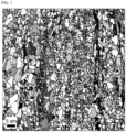
- FIG. 1 is a scanning electron microscope (SEM) image of a cross-section of the thickness center of an austenite stainless steel according to an embodiment of the present disclosure.
- An austenite stainless steel includes, in weight %, at least 0.05% but not more than 0.1% of C, at least 0.2% but not more than 0.7% of Si, at least 2.0% but not more than 4.0% of Mn, more than 0% but less than 0.1% of P, more than 0% but less than 0.01% of S, at least 17% but not more than 19% of Cr, at least 2.0% but not more than 4.0% of Ni, at least 1.0% but not more than 2.5% of Cu, at least 0.15% but not more than 0.25% of N, and the balance being iron (Fe) and inevitable impurities and is 5 ⁇ m or less in average grain diameter of the thickness center.
- An austenite stainless steel includes, in weight %, at least 0.05% but not more than 0.1% of C, at least 0.2% but not more than 0.7% of Si, at least 2.0% but not more than 4.0% of Mn, more than 0% but less than 0.1% of P, more than 0% but less than 0.01% of S, at least 17% but not more than 19% of Cr, at least 2.0% but not more than 4.0% of Ni, at least 1.0% but not more than 2.5% of Cu, at least 0.15% but not more than 0.25% of N, and the balance being iron (Fe) and inevitable impurities.
- the content of carbon (C) may be at least 0.05% but not more than 0.1%.
- Carbon (C) as an element effective on stabilizing an austenite phase, needs to be added in an appropriate amount to obtain a yield strength of a steel.
- C may be added in an amount of 0.05% or more.
- an excess of C may deteriorate cold workability due to the solid solution strengthening effect.
- an excess of C may cause grain boundary precipitation of a Cr carbide during a low-temperature annealing process, resulting in adverse effects on ductility and corrosion resistance.
- the upper limit of the C content may be controlled to 0.1%.
- the content of silicon (Si) may be at least 0.2% but not more than 0.7%.
- Si may be added for deoxidation of a steel and is an element effective on improving corrosion resistance.
- Si may be added in an amount of 0.2% or more.
- an excess of Si may promote formation of delta ferrite in a cast material due to the ferrite phase stabilization effect. Therefore, an excess of Si may deteriorate hot workability and adversely affect ductility and impact properties.
- the upper limit of the Si content may be controlled to 0.7%.
- Si may be added in an amount of at least 0.3% but not less than 0.4%.
- the content of manganese (Mn) may be at least 2.0% but not more than 4.0%.
- Mn is an austenite phase-stabilizing element added instead of Ni.
- Mn may be added in an amount of 2.0% or more.
- an excess of Mn may cause excessive formation of S-based inclusions (MnS) resulting in deterioration of ductility and corrosion resistance.
- the upper limit of the Mn content may be controlled to 4.0%.
- Mn may be added in an amount of at least 3.6% but not more than 3.9%.
- the content of phosphorus (P) may be more than 0% but less than 0.1%.
- P as an inevitable impurity contained in steels, is an element causing intergranular corrosion and deteriorating hot workability. Therefore, it is preferable to control the P content as low as possible. In consideration thereof, the upper limit of the P content may be controlled to less than 0.1%.
- the content of sulfur (S) may be more than 0% but less than 0.01%.
- S is an inevitable impurity contained in steels and is segregated in grain boundaries causing deterioration of hot workability. Therefore, it is preferable to control the S content as low as possible. In consideration thereof, the upper limit of the S content may be controlled to less than 0.01%.
- the content of chromium (Cr) may be at least 17% but not more than 19%.
- Cr is an element effective on inhibiting formation of a martensite phase and obtaining corrosion resistance.
- Cr may be added in an amount of 17% or more.
- an excess of Cr may increase manufacturing costs and form a large amount of delta ferrite in a material resulting in deterioration of hot workability.
- the upper limit of the Cr content may be controlled to 19%.
- Cr may be added in an amount of at least 17.2% but not more than 18%.
- the content of nickel (Ni) may be at least 2.0% but not more than 4.0%.
- Ni is essential to obtain excellent hot workability and cold workability. Therefore, although Mn is added in a certain level, Ni may be added in an amount of 2.0% or more. However, if the Ni content is excessive, a martensite transformation initiation temperature (Ms) becomes too low to form stress-induced martensite during cold working. In addition, an excess of Ni may cause an increase in costs of raw materials. In consideration thereof, the upper limit of the Ni content may be controlled to 4.0%. Preferably, Ni may be added in an amount of at least 3.4% but not more than 3.7%.
- the content of copper (Cu) may be at least 1.0% but not more than 2.5%.
- Cu as an austenite phase-stabilizing element, is effective on softening a material.
- Cu may be added in an amount of 1.0% or more.
- Ms martensite transformation initiation temperature
- an excess of Cu may cause an increase in costs of materials and hot brittleness.
- the upper limit of the Cu content may be controlled to 2.5%.
- Cu may be added in an amount of at least 1.5% but not more than 2.0%.
- the content of nitrogen (N) may be at least 0.15% but not more than 0.25%.
- N is an element effective on stabilization of an austenite phase and improvement of corrosion resistance.
- N may be added in an amount of 0.15% or more.
- Ms martensite transformation initiation temperature
- an excess of N may cause defects in quality due to pores formed during a casting process.
- the upper limit of the N content may be controlled to 0.25%.
- N may be added in an amount of at least 0.16% but not more than 0.21%.
- the remaining component of the composition of the present disclosure is iron (Fe).
- the composition may include unintended impurities inevitably incorporated from raw materials or surrounding environments, and thus addition of other alloy components is not excluded.
- the impurities are not specifically mentioned in the present disclosure, as they are known to any person skilled in the art of manufacturing.
- an average grain diameter in the thickness center may be 5 ⁇ m or less by realizing ultrafine grain characteristics.
- the thickness center refers to a region in a thickness range of 1/4t to 3/4t assuming that a total thickness of a stainless steel is t.
- the average refers to an average of values measured at random 5 points.
- the austenite stainless steel according to an embodiment of the present disclosure may have an austenite stability parameter (ASP), represented by Expression (1) below, of -30 to 30. 551 - 462 ⁇ ([C]+[N]) - 9.2 ⁇ [Si] - 8.1 ⁇ [Mn] - 13.7 ⁇ [Cr] - 29 ⁇ ([Ni]+[Cu])
- ASP austenite stability parameter
- [C], [N], [Si], [Mn], [Cr], [Ni], and [Cu] represent weight percentages (wt%) of respective elements.
- the value of Expression (1) refers to a temperature at which 50% of austenite is transformed into martensite in the case where a stainless steel is deformed to a true strain of 0.3 and may be used as an indicator of austenite phase stability.
- a lower value of Expression (1) indicates a higher austenite phase stability and a lower amount of strain-induced martensite transformed during deformation.
- Expression (1) If the value of Expression (1) is less than -30, an amount of TRIP transformation from the austenite phase into the martensite phase decreases, so that the amount of strain-induced martensite decreases. Therefore, if the value of Expression (1) is less than -30, a ratio of reverted austenite by low-temperature annealing decreases failing to obtain ultrafine grains. However, if the value of Expression (1) is greater than 30, TRIP transformation occurs too quickly so that yield strength and elongation may deteriorate.
- the austenite stainless steel according to an embodiment of the present disclosure may have a strength stability parameter (SSP), represented by Expression (2) below, of 0 or more.
- SSP strength stability parameter
- Expression (2) In the case where the value of Expression (2) is less than 0, it may be difficult to realize ultrafine microstructure characteristics in a wide range of final annealing temperature. That is, in order to realize ultrafine microstructure characteristics throughout the final annealing temperature range of 800 to 850°C suggested in the present disclosure, the value of Expression (2) needs to be controlled to 0 or more.
- the austenite stainless steel according to an embodiment of the present disclosure may have a pitting resistance equivalent number (PREN), represented by Expression (3) below, of 17 or more.
- PREN pitting resistance equivalent number
- the pitting potential value measured using a 3.5% NaCl solution (30°C) may not satisfy 200 mV or more. That is, in the case where the value of Expression (3) is less than 17, it may be difficult to achieve high corrosion resistance desired in the present disclosure.
- the ultrafine grain characteristics may be realized by the composition of alloying elements, parameters, and manufacturing method provided in the present disclosure. Therefore, the austenite stainless steel according to an embodiment of the present disclosure may have a yield strength of 600 MPa or more and an elongation of 30% or more.
- austenite stainless steel according to an embodiment of the present disclosure may have a pitting potential value of 200 mV or more.
- the austenite stainless steel according to an embodiment of the present disclosure may have a thickness of 0.4 to 2.0 mm.
- the embodiment is not limited thereto and the austenite stainless steel may be manufactured to have various thicknesses according to the purpose of use.
- a method for manufacturing an austenite stainless steel according to an embodiment of the present disclosure may include: manufacturing an ingot including, in weight %, at least 0.05% but not more than 0.1% of C, at least 0.2% but not more than 0.7% of Si, at least 2.0% but not more than 4.0% of Mn, more than 0% but less than 0.1% of P, more than 0% but less than 0.01% of S, at least 17% but not more than 19% of Cr, at least 2.0% but not more than 4.0% of Ni, at least 1.0% but not more than 2.5% of Cu, at least 0.15% but not more than 0.25% of N, and the balance being iron (Fe) and inevitable impurities; hot rolling the ingot into a hot-rolled steel sheet; cold rolling the hot-rolled steel sheet into a cold-rolled steel sheet; and final annealing the cold-rolled steel sheet.
- the ingot may have an austenite stability parameter (ASP), represented by Expression (1) below, of -30 to 30. 551 -462 ⁇ ([C]+[N]) - 9.2 ⁇ [Si] - 8.1 ⁇ [Mn] - 13.7 ⁇ [Cr] - 29 ⁇ ([Ni]+[Cu])
- ASP austenite stability parameter
- [C], [N], [Si], [Mn], [Cr], [Ni], and [Cu] represent weight percentages (wt%) of respective elements.
- the ingot may have a strength stability parameter (SSP), represented by Expression (2) below, of 0 or more.
- SSP strength stability parameter
- the ingot may have a pitting resistance equivalent number (PREN), represented by Expression (3) below, of 17 or more.
- PREN pitting resistance equivalent number
- slabs may be manufactured according to the purpose and use.
- an ingot satisfying the composition of alloying elements is manufactured and subject to a series of hot rolling, cold rolling, and final annealing processes.
- the ingot is heated to a temperature of 1150°C to 1300°C and hot-rolled into a hot-rolled steel sheet.
- the heating temperature In the case where the heating temperature is low, it may be difficult to redissolve coarse precipitates generated while manufacturing the ingot. In consideration thereof, the heating temperature may be 1150°C or higher. However, in the case where the heating temperature is high, internal grains may excessively coarsen resulting in severe surface oxidation causing surface defects. In consideration thereof, the upper limit of the heating temperature may be controlled to 1300°C.
- the method may further include intermediate annealing the hot-rolled steel sheet before the cold rolling.
- the intermediate annealing may be performed or omitted as needed.
- the intermediate annealing may be performed at a temperature of 1000 to 1150°C.
- the intermediate annealing is performed at a low temperature, a fraction of residual martensite may increase resulting in deterioration of workability. However, if the intermediate annealing is performed at a too high temperature, strength may decrease due to coarsening of grains.
- the final annealing may be performed at a temperature of 800 to 850°C.
- a too low final annealing temperature may deteriorate workability.
- strength may decrease due to coarsening of grains.
- the cold rolling may be performed at room temperature so that a thickness reductio of the hot-rolled steel sheet is 50% or more. If the thickness reduction ratio is less than 50% during cold rolling, the amount of strain-induced martensite decreases, so that the ultrafine reverted austenite phase decreases during low-temperature annealing making it difficult to obtain strength.
- compositions of alloying elements shown in Table 1 below were cast in a vacuum induction melting furnace in the form of 35 kg ingots with a thickness of 150 mm.
- the cast ingots were heated in a furnace at 1250°C for 2 hours and hot-rolled into hot-rolled steel sheets with a width of 200 mm and a thickness of 4 mm, and then air-cooled.
- the air-cooled hot-rolled steel sheets were intermediate-annealed at 1100°C for 1 minute, pickled, and cold-rolled into cold-rolled steel sheets to a thickness of 1.2 mm.
- the cold-rolled steel sheets were annealed at final annealing temperatures shown in Table 2, thereby manufacturing final products.
- [C], [N], [Si], [Mn], [Cr], [Ni], and [Cu] represent weight percentages (wt%) of respective elements.
- the average grain diameter was measured by obtaining images of a cross-section at the center of each steel by using a scanning electron microscope (SEM) with a model no. JSM-7001F.
- the pitting potential was measured by using a Potentiostat machine.
- a voltage was applied at a rate of 20 mV/min, a potential at which a current reached 100 ⁇ A was measured as the pitting potential.
- a temperature of the NaCl solution was 30°C and a concentration thereof was set to 3.5%. Meanwhile, a higher pitting potential indicates a better corrosion resistance.
- Examples 1 to 4 satisfied the composition of alloying elements, content ranges, parameters, and manufacturing processes proposed by the present disclosure. Therefore, Examples 1 to 4 satisfied the average grain diameter of 5 ⁇ m or less, the yield strength 600 MPa or more, the elongation of 30% or more, and the pitting potential value of 200 mV or more. That is, Examples 1 to 4 satisfied all of high strength, high ductility and high corrosion resistance.
- the value of Equation (1) did not satisfy the range of -30 to 30 and the value of Equation (2) did not satisfy the range of 0 or more. Therefore, the grain diameter of 5 ⁇ m or less and the yield strength of 600 MPa or more were not satisfied. In particular, it was difficult to realize ultrafine microstructure characteristics in the range of 800 to 850°C that is the final annealing temperature range suggested in the present disclosure.
- FIG. 1 is a scanning electron microscope (SEM) image of a cross-section of the thickness center of an austenite stainless steel according to an embodiment of the present disclosure.
- the average grain diameter at the thickness center of the austenite stainless steel according to an embodiment of the present disclosure satisfies the range of 5 ⁇ m or less. That is, according to an embodiment of the present disclosure, ultrafine grain characteristics may be realized.
- an austenite stainless steel having high strength, high ductility, and high corrosion resistance by realizing ultrafine grain characteristics as well as price competitiveness and a manufacturing method therefor. Therefore, industrial applicability of the present disclosure is apparent from the above description.
Landscapes
- Chemical & Material Sciences (AREA)
- Engineering & Computer Science (AREA)
- Mechanical Engineering (AREA)
- Materials Engineering (AREA)
- Metallurgy (AREA)
- Organic Chemistry (AREA)
- Physics & Mathematics (AREA)
- Thermal Sciences (AREA)
- Crystallography & Structural Chemistry (AREA)
- Heat Treatment Of Sheet Steel (AREA)
- Heat Treatment Of Steel (AREA)
Abstract
Description
- The present disclosure relates to an austenite stainless steel and a manufacturing method therefor, and more particularly, to an austenite stainless steel having high strength, high ductility, and improved corrosion resistance by realizing ultrafine grain characteristics and a manufacturing method therefor.
- 304 steels, as common austenite stainless steels, having a yield strength of 200 MPa to 350 MPa are limited in application as structural members. 304 steels are subject to an additional skin pass rolling process to obtain a higher yield strength, but this process causes an increase in costs and rapid decreases in elongation and formability. In addition, 304 steels including large amounts high-priced alloying elements have a problem of low price competitiveness.
- Patent Document 0001 discloses an austenite stainless steel and a manufacturing method therefor. Although an austenite stainless steel having a tensile strength of 600 MPa or more is disclosed, price competitiveness decreases due to a high Ni content.
- Meanwhile, grain refinement technology has drawn attention as a technology to improve both strength and ductility. Particularly, as a method for manufacturing ultrafine-grained steels for structural members, severe plastic deformation (SPD) has drawn attention. Severe plastic deformation is a method for realizing fine grains by generating new grain boundaries in existing grain boundaries by applying a strong sheer stress to a material. However, severe plastic deformation have problems such as a decrease in productivity and a limitation in product size.
- Patent Document 0002 discloses a method including heat treatment performed at a temperature of 600 to 700°C for a long time over 48 hours to obtain an average grain size of 10 µm or less. However, according to method disclosed in Patent Document 0002, there are problems of a decrease in productivity and an increase in manufacturing costs.
-
- Patent Document 0001:
Korean Patent Application Publication No. 10-2016-0138277 (Date of Publication: December 2, 2016 - Patent Document 0002:
Japanese Patent Application Laid-Open No. 2020-050940 (Date of Publication: April 2, 2020 - The present disclosure has been proposed to solve the above-described problems, and provided is an austenite stainless steel having high strength, high ductility, and high corrosion resistance by realizing ultrafine grain characteristics as well as price competitiveness.
- An austenite stainless steel according to an embodiment of the present disclosure includes, in weight %, at least 0.05% but not more than 0.1% of C, at least 0.2% but not more than 0.7% of Si, at least 2.0% but not more than 4.0% of Mn, more than 0% but less than 0.1% of P, more than 0% but less than 0.01% of S, at least 17% but not more than 19% of Cr, at least 2.0% but not more than 4.0% of Ni, at least 1.0% but not more than 2.5% of Cu, at least 0.15% but not more than 0.25% of N, and the balance being iron (Fe) and inevitable impurities and is 5 µm or less in average grain diameter of the thickness center.
- In addition, the austenite stainless steel according to an embodiment of the present disclosure may have an austenite stability parameter (ASP), represented by Expression (1) below, of -30 to 30.
551 - 462×([C]+[N]) - 9.2×[Si] - 8.1×[Mn] - 13.7×[Cr] - 29×([Ni]+[Cu]) - In Expression (1), [C], [N], [Si], [Mn], [Cr], [Ni], and [Cu] represent weight percentages (wt%) of respective elements.
- In addition, the austenite stainless steel according to an embodiment of the present disclosure may have a strength stability parameter (SSP), represented by Expression (2) below, of 0 or more.
58 + 132×[C] - 7.9×[Si] + 1.0×[Mn] - 5.6×[Cr] + 7.0×[Ni] + 3.9×[Cu] + 1.7×[N] - In Expression (2), [C], [Si], [Mn], [Cr], [Ni], [Cu], and [N] represent weight percentages (wt%) of respective elements.
- In addition, the austenite stainless steel according to an embodiment of the present disclosure, may have a pitting resistance equivalent number (PREN), represented by Expression (3) below, of 17 or more.

- In Expression (3), [Cr], [Mn], and [N] represent weight percentages (wt%) of respective elements.
- In addition, the austenite stainless steel according to an embodiment of the present disclosure may have a yield strength of 600 MPa or more.
- In addition, the austenite stainless steel according to an embodiment of the present disclosure may have an elongation of 30% or more.
- In addition, the austenite stainless steel according to an embodiment of the present disclosure may have a pitting potential value of 200 mV or more.
- In addition, the austenite stainless steel according to an embodiment of the present disclosure may have a thickness of 0.4 to 2.0 mm.
- In addition, a method for manufacturing an austenite stainless steel according to an embodiment of the present disclosure may include: manufacturing an ingot including, in weight %, at least 0.05% but not more than 0.1% of C, at least 0.2% but not more than 0.7% of Si, at least 2.0% but not more than 4.0% of Mn, more than 0% but less than 0.1% of P, more than 0% but less than 0.01% of S, at least 17% but not more than 19% of Cr, at least 2.0% but not more than 4.0% of Ni, at least 1.0% but not more than 2.5% of Cu, at least 0.15% but not more than 0.25% of N, and the balance being iron (Fe) and inevitable impurities; hot rolling the ingot into a hot-rolled steel sheet; cold rolling the hot-rolled steel sheet into a cold-rolled steel sheet; and final annealing the cold-rolled steel sheet.
- In addition, in the method for manufacturing an austenite stainless steel according to an embodiment of the present disclosure, the ingot may have an austenite stability parameter (ASP), represented by Expression (1) below, of -30 to 30.
551 - 462×([C]+[N]) - 9.2×[Si] - 8.1×[Mn] - 13.7×[Cr] - 29×([Ni]+[Cu]) - In Expression (1), [C], [N], [Si], [Mn], [Cr], [Ni], and [Cu] represent weight percentages (wt%) of respective elements.
- In addition, in the method for manufacturing an austenite stainless steel according to an embodiment of the present disclosure, the ingot may have a strength stability parameter (SSP), represented by Expression (2) below, of 0 or more.
58 + 132×[C] - 7.9×[Si] + 1.0×[Mn] - 5.6×[Cr] + 7.0×[Ni] + 3.9×[Cu] + 1.7×[N] - In Expression (2), [C], [Si], [Mn], [Cr], [Ni], [Cu], and [N] represent weight percentages (wt%) of respective elements.
- In addition, in the method for manufacturing an austenite stainless steel according to an embodiment of the present disclosure, the ingot may have a pitting resistance equivalent number (PREN), represented by Expression (3) below, of 17 or more.

- In Expression (3), [Cr], [Mn], and [N] represent weight percentages (wt%) of respective elements.
- In addition, the method for manufacturing an austenite stainless steel according to an embodiment of the present disclosure may further include intermediate annealing the hot-rolled steel sheet before the cold rolling.
- In addition, in the method for manufacturing an austenite stainless steel according to an embodiment of the present disclosure, the intermediate annealing may be performed at a temperature of 1050 to 1150°C.
- In addition, in the method for manufacturing an austenite stainless steel according to an embodiment of the present disclosure, the final annealing may be performed at a temperature of 800 to 850°C.
- In addition, in the method for manufacturing an austenite stainless steel according to an embodiment of the present disclosure, the cold rolling may be performed at room temperature such that a thickness reduction ratio of the hot-rolled steel sheet is 50% or more.
- According to an embodiment of the present disclosure, provided are an austenite stainless steel having high strength, high ductility, and high corrosion resistance by realizing ultrafine grain characteristics as well as price competitiveness and a manufacturing method therefor.
-
FIG. 1 is a scanning electron microscope (SEM) image of a cross-section of the thickness center of an austenite stainless steel according to an embodiment of the present disclosure. - An austenite stainless steel according to an embodiment of the present disclosure includes, in weight %, at least 0.05% but not more than 0.1% of C, at least 0.2% but not more than 0.7% of Si, at least 2.0% but not more than 4.0% of Mn, more than 0% but less than 0.1% of P, more than 0% but less than 0.01% of S, at least 17% but not more than 19% of Cr, at least 2.0% but not more than 4.0% of Ni, at least 1.0% but not more than 2.5% of Cu, at least 0.15% but not more than 0.25% of N, and the balance being iron (Fe) and inevitable impurities and is 5 µm or less in average grain diameter of the thickness center.
- Hereinafter, embodiments of the present disclosure will be described in detail with reference to the accompanying drawings. These embodiments are provided so that this disclosure will be thorough and complete, and will fully convey the concept of the invention to those skilled in the art. The embodiments of the present disclosure may, however, be embodied in many different forms and should not be construed as being limited to the embodiments set forth herein. In the drawings, parts unrelated to the descriptions are omitted for clear description of the disclosure and sizes of elements may be exaggerated for clarity.
- Throughout the specification, the term "include" an element does not preclude other elements but may further include another element, unless otherwise stated.
- As used herein, the singular forms are intended to include the plural forms as well, unless the context clearly indicates otherwise.
- Hereinafter, reasons for numerical limitations on the contents of alloying elements in the embodiment of the present disclosure will be described. Hereinafter, the unit of the component indicates wt% unless otherwise stated.
- An austenite stainless steel according to an embodiment of the present disclosure includes, in weight %, at least 0.05% but not more than 0.1% of C, at least 0.2% but not more than 0.7% of Si, at least 2.0% but not more than 4.0% of Mn, more than 0% but less than 0.1% of P, more than 0% but less than 0.01% of S, at least 17% but not more than 19% of Cr, at least 2.0% but not more than 4.0% of Ni, at least 1.0% but not more than 2.5% of Cu, at least 0.15% but not more than 0.25% of N, and the balance being iron (Fe) and inevitable impurities.
- The content of carbon (C) may be at least 0.05% but not more than 0.1%.
- Carbon (C), as an element effective on stabilizing an austenite phase, needs to be added in an appropriate amount to obtain a yield strength of a steel. In consideration thereof, C may be added in an amount of 0.05% or more. However, an excess of C may deteriorate cold workability due to the solid solution strengthening effect. In addition, an excess of C may cause grain boundary precipitation of a Cr carbide during a low-temperature annealing process, resulting in adverse effects on ductility and corrosion resistance. In consideration thereof, the upper limit of the C content may be controlled to 0.1%.
- The content of silicon (Si) may be at least 0.2% but not more than 0.7%.
- Si may be added for deoxidation of a steel and is an element effective on improving corrosion resistance. In consideration thereof, Si may be added in an amount of 0.2% or more. However, an excess of Si may promote formation of delta ferrite in a cast material due to the ferrite phase stabilization effect. Therefore, an excess of Si may deteriorate hot workability and adversely affect ductility and impact properties. In consideration thereof, the upper limit of the Si content may be controlled to 0.7%. Preferably, Si may be added in an amount of at least 0.3% but not less than 0.4%.
- The content of manganese (Mn) may be at least 2.0% but not more than 4.0%.
- In the present disclosure, Mn is an austenite phase-stabilizing element added instead of Ni. In consideration thereof, Mn may be added in an amount of 2.0% or more. However, an excess of Mn may cause excessive formation of S-based inclusions (MnS) resulting in deterioration of ductility and corrosion resistance. In consideration thereof, the upper limit of the Mn content may be controlled to 4.0%. Preferably, Mn may be added in an amount of at least 3.6% but not more than 3.9%.
- The content of phosphorus (P) may be more than 0% but less than 0.1%.
- P, as an inevitable impurity contained in steels, is an element causing intergranular corrosion and deteriorating hot workability. Therefore, it is preferable to control the P content as low as possible. In consideration thereof, the upper limit of the P content may be controlled to less than 0.1%.
- The content of sulfur (S) may be more than 0% but less than 0.01%.
- Like P, S is an inevitable impurity contained in steels and is segregated in grain boundaries causing deterioration of hot workability. Therefore, it is preferable to control the S content as low as possible. In consideration thereof, the upper limit of the S content may be controlled to less than 0.01%.
- The content of chromium (Cr) may be at least 17% but not more than 19%.
- Cr is an element effective on inhibiting formation of a martensite phase and obtaining corrosion resistance. In consideration thereof, Cr may be added in an amount of 17% or more. However, an excess of Cr may increase manufacturing costs and form a large amount of delta ferrite in a material resulting in deterioration of hot workability. In consideration thereof, the upper limit of the Cr content may be controlled to 19%. Preferably, Cr may be added in an amount of at least 17.2% but not more than 18%.
- The content of nickel (Ni) may be at least 2.0% but not more than 4.0%.
- As a strong austenite phase-stabilizing element, Ni is essential to obtain excellent hot workability and cold workability. Therefore, although Mn is added in a certain level, Ni may be added in an amount of 2.0% or more. However, if the Ni content is excessive, a martensite transformation initiation temperature (Ms) becomes too low to form stress-induced martensite during cold working. In addition, an excess of Ni may cause an increase in costs of raw materials. In consideration thereof, the upper limit of the Ni content may be controlled to 4.0%. Preferably, Ni may be added in an amount of at least 3.4% but not more than 3.7%.
- The content of copper (Cu) may be at least 1.0% but not more than 2.5%.
- Cu, as an austenite phase-stabilizing element, is effective on softening a material. In consideration thereof, Cu may be added in an amount of 1.0% or more. However, if the Cu content is excessive, a martensite transformation initiation temperature (Ms) becomes too low to form stress-induced martensite during cold working. In addition, an excess of Cu may cause an increase in costs of materials and hot brittleness. In consideration thereof, the upper limit of the Cu content may be controlled to 2.5%. Preferably, Cu may be added in an amount of at least 1.5% but not more than 2.0%.
- The content of nitrogen (N) may be at least 0.15% but not more than 0.25%.
- N is an element effective on stabilization of an austenite phase and improvement of corrosion resistance. In consideration thereof, N may be added in an amount of 0.15% or more. However, when the N content is excessive, cold workability may deteriorate due to the solid solution strengthening effect and a martensite transformation initiation temperature (Ms) becomes too low to form stress-induced martensite during cold working. In addition, an excess of N may cause defects in quality due to pores formed during a casting process. In consideration thereof, the upper limit of the N content may be controlled to 0.25%. Preferably, N may be added in an amount of at least 0.16% but not more than 0.21%.
- The remaining component of the composition of the present disclosure is iron (Fe). However, the composition may include unintended impurities inevitably incorporated from raw materials or surrounding environments, and thus addition of other alloy components is not excluded. The impurities are not specifically mentioned in the present disclosure, as they are known to any person skilled in the art of manufacturing.
- In the austenite stainless steel according to an embodiment of the present disclosure, an average grain diameter in the thickness center may be 5 µm or less by realizing ultrafine grain characteristics. In this regard, the thickness center refers to a region in a thickness range of 1/4t to 3/4t assuming that a total thickness of a stainless steel is t.
- Meanwhile, as used herein, the average refers to an average of values measured at random 5 points.
- The austenite stainless steel according to an embodiment of the present disclosure may have an austenite stability parameter (ASP), represented by Expression (1) below, of -30 to 30.
551 - 462×([C]+[N]) - 9.2×[Si] - 8.1×[Mn] - 13.7×[Cr] - 29×([Ni]+[Cu]) - In Expression (1), [C], [N], [Si], [Mn], [Cr], [Ni], and [Cu] represent weight percentages (wt%) of respective elements.
- The value of Expression (1) refers to a temperature at which 50% of austenite is transformed into martensite in the case where a stainless steel is deformed to a true strain of 0.3 and may be used as an indicator of austenite phase stability. A lower value of Expression (1) indicates a higher austenite phase stability and a lower amount of strain-induced martensite transformed during deformation.
- If the value of Expression (1) is less than -30, an amount of TRIP transformation from the austenite phase into the martensite phase decreases, so that the amount of strain-induced martensite decreases. Therefore, if the value of Expression (1) is less than -30, a ratio of reverted austenite by low-temperature annealing decreases failing to obtain ultrafine grains. However, if the value of Expression (1) is greater than 30, TRIP transformation occurs too quickly so that yield strength and elongation may deteriorate.
- The austenite stainless steel according to an embodiment of the present disclosure may have a strength stability parameter (SSP), represented by Expression (2) below, of 0 or more.
58 + 132×[C] - 7.9×[Si] + 1.0×[Mn] - 5.6×[Cr] + 7.0×[Ni] + 3.9×[Cu] + 1.7×[N] - In Expression (2), [C], [Si], [Mn], [Cr], [Ni], [Cu], and [N] represent weight percentages (wt%) of respective elements.
- In the case where the value of Expression (2) is less than 0, it may be difficult to realize ultrafine microstructure characteristics in a wide range of final annealing temperature. That is, in order to realize ultrafine microstructure characteristics throughout the final annealing temperature range of 800 to 850°C suggested in the present disclosure, the value of Expression (2) needs to be controlled to 0 or more.
- The austenite stainless steel according to an embodiment of the present disclosure may have a pitting resistance equivalent number (PREN), represented by Expression (3) below, of 17 or more.

- In Expression (3), [Cr], [Mn], and [N] represent weight percentages (wt%) of respective elements.
- In the case where the value of Expression (3) is less than 17, the pitting potential value measured using a 3.5% NaCl solution (30°C) may not satisfy 200 mV or more. That is, in the case where the value of Expression (3) is less than 17, it may be difficult to achieve high corrosion resistance desired in the present disclosure.
- The ultrafine grain characteristics may be realized by the composition of alloying elements, parameters, and manufacturing method provided in the present disclosure. Therefore, the austenite stainless steel according to an embodiment of the present disclosure may have a yield strength of 600 MPa or more and an elongation of 30% or more.
- In addition, the austenite stainless steel according to an embodiment of the present disclosure may have a pitting potential value of 200 mV or more.
- The austenite stainless steel according to an embodiment of the present disclosure may have a thickness of 0.4 to 2.0 mm. However, the embodiment is not limited thereto and the austenite stainless steel may be manufactured to have various thicknesses according to the purpose of use.
- Hereinafter, a method for manufacturing an austenite stainless steel according to another embodiment of the present disclosure will be described.
- A method for manufacturing an austenite stainless steel according to an embodiment of the present disclosure may include: manufacturing an ingot including, in weight %, at least 0.05% but not more than 0.1% of C, at least 0.2% but not more than 0.7% of Si, at least 2.0% but not more than 4.0% of Mn, more than 0% but less than 0.1% of P, more than 0% but less than 0.01% of S, at least 17% but not more than 19% of Cr, at least 2.0% but not more than 4.0% of Ni, at least 1.0% but not more than 2.5% of Cu, at least 0.15% but not more than 0.25% of N, and the balance being iron (Fe) and inevitable impurities; hot rolling the ingot into a hot-rolled steel sheet; cold rolling the hot-rolled steel sheet into a cold-rolled steel sheet; and final annealing the cold-rolled steel sheet.
- The ingot may have an austenite stability parameter (ASP), represented by Expression (1) below, of -30 to 30.
551 -462×([C]+[N]) - 9.2×[Si] - 8.1×[Mn] - 13.7×[Cr] - 29×([Ni]+[Cu]) - In Expression (1), [C], [N], [Si], [Mn], [Cr], [Ni], and [Cu] represent weight percentages (wt%) of respective elements.
- In addition, in the method for manufacturing an austenite stainless steel according to an embodiment of the present disclosure, the ingot may have a strength stability parameter (SSP), represented by Expression (2) below, of 0 or more.
58 + 132×[C] - 7.9×[Si] + 1.0×[Mn] - 5.6×[Cr] + 7.0×[Ni] + 3.9×[Cu] + 1.7×[N] - In Expression (2), [C], [Si], [Mn], [Cr], [Ni], [Cu], and [N] represent weight percentages (wt%) of respective elements.
- In addition, in the method for manufacturing an austenite stainless steel according to an embodiment of the present disclosure, the ingot may have a pitting resistance equivalent number (PREN), represented by Expression (3) below, of 17 or more.

- In Expression (3), [Cr], [Mn], and [N] represent weight percentages (wt%) of respective elements.
- Meanwhile, instead of ingots, slabs may be manufactured according to the purpose and use.
- Numerical limitations on the content ranges of alloying elements and values of Expression (1), Expression (2), and Expression (3) are as described above and each step of the manufacturing process will be described in more detail.
- First, an ingot satisfying the composition of alloying elements is manufactured and subject to a series of hot rolling, cold rolling, and final annealing processes.
- First, the ingot is heated to a temperature of 1150°C to 1300°C and hot-rolled into a hot-rolled steel sheet.
- In the case where the heating temperature is low, it may be difficult to redissolve coarse precipitates generated while manufacturing the ingot. In consideration thereof, the heating temperature may be 1150°C or higher. However, in the case where the heating temperature is high, internal grains may excessively coarsen resulting in severe surface oxidation causing surface defects. In consideration thereof, the upper limit of the heating temperature may be controlled to 1300°C.
- Next, the method may further include intermediate annealing the hot-rolled steel sheet before the cold rolling. The intermediate annealing may be performed or omitted as needed.
- In the case of performing the intermediate annealing, the intermediate annealing may be performed at a temperature of 1000 to 1150°C.
- If the intermediate annealing is performed at a low temperature, a fraction of residual martensite may increase resulting in deterioration of workability. However, if the intermediate annealing is performed at a too high temperature, strength may decrease due to coarsening of grains.
- The final annealing may be performed at a temperature of 800 to 850°C.
- Like the intermediate annealing temperature, a too low final annealing temperature may deteriorate workability. However, in the case where the final annealing temperature is too high, strength may decrease due to coarsening of grains.
- The cold rolling may be performed at room temperature so that a thickness reductio of the hot-rolled steel sheet is 50% or more. If the thickness reduction ratio is less than 50% during cold rolling, the amount of strain-induced martensite decreases, so that the ultrafine reverted austenite phase decreases during low-temperature annealing making it difficult to obtain strength.
- Hereinafter, the present disclosure will be described in more detail through following examples. However, it is necessary to note that the following examples are only intended to illustrate the present disclosure in more detail and are not intended to limit the scope of the present disclosure. This is because the scope of the present disclosure is determined by matters described in the claims and able to be reasonably inferred therefrom.
- Various compositions of alloying elements shown in Table 1 below were cast in a vacuum induction melting furnace in the form of 35 kg ingots with a thickness of 150 mm. The cast ingots were heated in a furnace at 1250°C for 2 hours and hot-rolled into hot-rolled steel sheets with a width of 200 mm and a thickness of 4 mm, and then air-cooled. The air-cooled hot-rolled steel sheets were intermediate-annealed at 1100°C for 1 minute, pickled, and cold-rolled into cold-rolled steel sheets to a thickness of 1.2 mm. The cold-rolled steel sheets were annealed at final annealing temperatures shown in Table 2, thereby manufacturing final products.
[Table 1] Category Composition of alloying elements C Si Mn Cr Ni Cu N Example 1 0.1 0.4 3.9 18 3.5 1.5 0.21 Example 2 0.06 0.3 3.7 17.7 3.6 1.9 0.18 Example 3 0.05 0.3 3.6 17.7 3.7 2.0 0.2 Example 4 0.07 0.4 3.6 17.2 3.4 1.7 0.16 Comparative Example 1 0.06 0.6 4.3 18.7 4.2 1.4 0.22 Comparative Example 2 0.07 0.6 5.7 16.7 2.4 1.5 0.15 Comparative Example 3 0.08 0.4 2.9 17.3 2.8 1.3 0.17 Comparative Example 4 0.05 0.5 5.1 16.8 4.1 1.8 0.15 - In Table 2 below, values of Expression (1), Expression (2), and Expression (3), final annealing temperatures, average grain diameters, pitting potentials, yield strengths, and elongations are shown. The value of Expression (1) was obtained by calculation using Expression (1).
551 - 462×([C]+[N]) - 9.2×[Si] - 8.1×[Mn] - 13.7×[Cr] - 29×([Ni]+[Cu]) - In Expression (1), [C], [N], [Si], [Mn], [Cr], [Ni], and [Cu] represent weight percentages (wt%) of respective elements.
- The value of Expression (2) was obtained by calculation using Expression (2).
58 + 132×[C] - 7.9×[Si] + 1.0×[Mn] - 5.6×[Cr] + 7.0×[Ni] + 3.9×[Cu] + 1.7×[N] - In Expression (2), [C], [Si], [Mn], [Cr], [Ni], [Cu], and [N] represent weight percentages (wt%) of respective elements.
- The value of Expression (3) was obtained by calculation using Expression (3).

- In Expression (3), [Cr], [Mn], and [N] represent weight percentages (wt%) of respective elements.
- The average grain diameter was measured by obtaining images of a cross-section at the center of each steel by using a scanning electron microscope (SEM) with a model no. JSM-7001F.
- The pitting potential was measured by using a Potentiostat machine. In this regard, when a steel was immersed and a voltage was applied at a rate of 20 mV/min, a potential at which a current reached 100 µA was measured as the pitting potential. Here, a temperature of the NaCl solution was 30°C and a concentration thereof was set to 3.5%. Meanwhile, a higher pitting potential indicates a better corrosion resistance.
- Yield strength and elongation were measured by using a Zwick Roell tensile tester. A JIS13B tensile test specimen was tested at room temperature at a tensile speed of 15 mm per minute.
[Table 2] Category Expre ssion (1) Expre ssion (2) Express ion (3) Final annealing temperatur e (°C) Average grain diameter (µm) Pitting potenti al (mV) Yield strength (MPa) Elongati on (%) Example 1 -19 1.8 19.4 800 3.2 309 679 36.0 850 4.1 318 622 38.5 Example 2 5 1.0 18.7 800 2.9 273 678 35.8 850 4.4 281 613 38.4 Example 3 -4.2 0.7 19.7 800 2.9 276 660 38.6 850 4.1 284 610 41.4 Example 4 28 2.1 18.0 800 3.8 233 666 35.9 850 4.6 240 624 37.9 Comparative Example 1 -37 -4 20.1 800 3.9 344 608 41.9 850 8.6 354 557 42.6 Comparative Example 2 56 -2.4 16.3 800 3.2 143 657 38.7 850 7.4 147 576 42.0 Comparative Example 3 52 -3.6 18.6 800 4.5 265 614 37.9 850 8.9 273 562 42.2 Comparative Example 4 11 7.6 16.7 800 3.1 169 762 29.4 850 4.1 164 676 36.5 - Referring to Table 2, Examples 1 to 4 satisfied the composition of alloying elements, content ranges, parameters, and manufacturing processes proposed by the present disclosure. Therefore, Examples 1 to 4 satisfied the average grain diameter of 5 µm or less, the yield strength 600 MPa or more, the elongation of 30% or more, and the pitting potential value of 200 mV or more. That is, Examples 1 to 4 satisfied all of high strength, high ductility and high corrosion resistance. However, in the case of Comparative Examples 1 to 3, the value of Equation (1) did not satisfy the range of -30 to 30 and the value of Equation (2) did not satisfy the range of 0 or more. Therefore, the grain diameter of 5 µm or less and the yield strength of 600 MPa or more were not satisfied. In particular, it was difficult to realize ultrafine microstructure characteristics in the range of 800 to 850°C that is the final annealing temperature range suggested in the present disclosure.
- In the case of Comparative Examples 2 and 4, the value of Equation (3) did not satisfy the range of 17 or more due to the excessive Mn content. Therefore, in the case of Comparative Examples 2 and 4, the pitting potential value did not satisfy the range of 200 mV or more. That is, Comparative Examples 2 and 4 exhibited inferior corrosion resistance.
-
FIG. 1 is a scanning electron microscope (SEM) image of a cross-section of the thickness center of an austenite stainless steel according to an embodiment of the present disclosure. - Referring to
FIG. 1 , it may be confirmed that the average grain diameter at the thickness center of the austenite stainless steel according to an embodiment of the present disclosure satisfies the range of 5 µm or less. That is, according to an embodiment of the present disclosure, ultrafine grain characteristics may be realized. - According to the present disclosure, provided are an austenite stainless steel having high strength, high ductility, and high corrosion resistance by realizing ultrafine grain characteristics as well as price competitiveness and a manufacturing method therefor. Therefore, industrial applicability of the present disclosure is apparent from the above description.
Claims (16)
- An austenite stainless steel comprising, in weight %, at least 0.05% but not more than 0.1% of C, at least 0.2% but not more than 0.7% of Si, at least 2.0% but not more than 4.0% of Mn, more than 0% but less than 0.1% of P, more than 0% but less than 0.01% of S, at least 17% but not more than 19% of Cr, at least 2.0% but not more than 4.0% of Ni, at least 1.0% but not more than 2.5% of Cu, at least 0.15% but not more than 0.25% of N, and the balance being iron (Fe) and inevitable impurities,
wherein an average grain diameter of the thickness center is 5 µm or less. - The austenite stainless steel according to claim 1, wherein an austenite stability parameter (ASP) represented by Expression (1) below is -30 to 30:
551 - 462×([C]+[N]) - 9.2×[Si] - 8.1×[Mn] - 13.7×[Cr] - 29×([Ni]+[Cu]) - The austenite stainless steel according to claim 1, wherein a strength stability parameter (SSP) represented by Expression (2) below is 0 or more:
58 + 132×[C] - 7.9×[Si] + 1.0×[Mn] - 5.6×[Cr] + 7.0×[Ni] + 3.9×[Cu] + 1.7×[N] - The austenite stainless steel according to claim 1, wherein a pitting resistance equivalent number (PREN) represented by Expression (3) below is 17 or more:

- The austenite stainless steel according to claim 1, wherein a yield strength is 600 MPa or more.
- The austenite stainless steel according to claim 1, wherein an elongation is 30% or more.
- The austenite stainless steel according to claim 1, wherein a pitting potential value is 200 mV or more.
- The austenite stainless steel according to claim 1, wherein a thickness is 0.4 mm to 2.0 mm.
- A method for manufacturing an austenite stainless steel, the method comprising:manufacturing an ingot including, in weight %, at least 0.05% but not more than 0.1% of C, at least 0.2% but not more than 0.7% of Si, at least 2.0% but not more than 4.0% of Mn, more than 0% but less than 0.1% of P, more than 0% but less than 0.01% of S, at least 17% but not more than 19% of Cr, at least 2.0% but not more than 4.0% of Ni, at least 1.0% but not more than 2.5% of Cu, at least 0.15% but not more than 0.25% of N, and the balance being iron (Fe) and inevitable impurities;hot rolling the ingot into a hot-rolled steel sheet;cold rolling the hot-rolled steel sheet into a cold-rolled steel sheet; andfinal annealing the cold-rolled steel sheet.
- The method according to claim 9, wherein the ingot has an austenite stability parameter (ASP), represented by Expression (1) below, of -30 to 30:
551 - 462×([C]+[N]) - 9.2×[Si] - 8.1×[Mn] - 13.7×[Cr] - 29×([Ni]+[Cu]) - The method according to claim 9, wherein the ingot has a strength stability parameter (SSP), represented by Expression (2) below, of 0 or more:
58 + 132×[C] - 7.9×[Si] + 1.0×[Mn] - 5.6×[Cr] + 7.0×[Ni] + 3.9×[Cu] + 1.7×[N] - The method according to claim 9, wherein the ingot has a pitting resistance equivalent number (PREN), represented by Expression (3) below, of 17 or more:

- The method according to claim 9, further comprising intermediate annealing the hot-rolled steel sheet before the cold rolling.
- The method according to claim 13, wherein the intermediate annealing is performed at a temperature of 1050°C to 1150°C.
- The method according to claim 9, wherein the final annealing is performed at a temperature of 800°C to 850°C.
- The method according to claim 9, wherein the cold rolling is performed to adjust a thickness reduction ratio of the hot rolled steel sheet to 50% or more.
Applications Claiming Priority (2)
| Application Number | Priority Date | Filing Date | Title |
|---|---|---|---|
| KR1020220066938A KR20230166672A (en) | 2022-05-31 | 2022-05-31 | Austenite stainless steel and manufacturing method |
| PCT/KR2023/003279 WO2023234525A1 (en) | 2022-05-31 | 2023-03-10 | Austenite stainless steel and manufacturing method therefor |
Publications (2)
| Publication Number | Publication Date |
|---|---|
| EP4509633A1 true EP4509633A1 (en) | 2025-02-19 |
| EP4509633A4 EP4509633A4 (en) | 2026-04-15 |
Family
ID=89025228
Family Applications (1)
| Application Number | Title | Priority Date | Filing Date |
|---|---|---|---|
| EP23816194.7A Pending EP4509633A4 (en) | 2022-05-31 | 2023-03-10 | AUSTENITIC STAINLESS STEEL AND MANUFACTURING PROCESSES FOR IT |
Country Status (6)
| Country | Link |
|---|---|
| US (1) | US20250333812A1 (en) |
| EP (1) | EP4509633A4 (en) |
| JP (1) | JP2025517789A (en) |
| KR (1) | KR20230166672A (en) |
| CN (1) | CN119234051A (en) |
| WO (1) | WO2023234525A1 (en) |
Family Cites Families (19)
| Publication number | Priority date | Publication date | Assignee | Title |
|---|---|---|---|---|
| US3904401A (en) * | 1974-03-21 | 1975-09-09 | Carpenter Technology Corp | Corrosion resistant austenitic stainless steel |
| US4222773A (en) * | 1979-05-29 | 1980-09-16 | Fagersta Ab | Corrosion resistant austenitic stainless steel containing 0.1 to 0.3 percent manganese |
| US4295769A (en) * | 1980-02-28 | 1981-10-20 | Armco Inc. | Copper and nitrogen containing austenitic stainless steel and fastener |
| AT412727B (en) * | 2003-12-03 | 2005-06-27 | Boehler Edelstahl | CORROSION RESISTANT, AUSTENITIC STEEL ALLOY |
| JP2008038191A (en) * | 2006-08-04 | 2008-02-21 | Nippon Metal Ind Co Ltd | Austenitic stainless steel and its manufacturing method |
| CN101765671B (en) * | 2007-08-02 | 2012-01-11 | 新日铁住金不锈钢株式会社 | Ferritic-austenitic stainless steel excellent in corrosion resistance and workability and manufacturing method thereof |
| WO2015087376A1 (en) * | 2013-12-09 | 2015-06-18 | 新日鐵住金株式会社 | Austenitic stainless steel sheet and method for producing same |
| JP5896089B1 (en) | 2014-04-17 | 2016-03-30 | 新日鐵住金株式会社 | Austenitic stainless steel and manufacturing method thereof |
| FI127274B (en) * | 2014-08-21 | 2018-02-28 | Outokumpu Oy | AUSTENITIC STAINLESS STEEL WITH HIGH STABILITY AND ITS PRODUCTION METHOD |
| JP6623761B2 (en) * | 2016-01-04 | 2019-12-25 | 日本製鉄株式会社 | Manufacturing method of metastable austenitic stainless steel |
| WO2017209431A1 (en) * | 2016-05-31 | 2017-12-07 | 주식회사 포스코 | Austenitic stainless steel having improved corrosion-resistance and workability and method for producing same |
| KR101952808B1 (en) * | 2017-08-22 | 2019-02-28 | 주식회사포스코 | Low nickel austenitic stainless steel having excellent hot workability and hydrogen embrittlement resistance |
| KR101977492B1 (en) * | 2017-11-10 | 2019-08-28 | 주식회사 포스코 | Austenitic stainless steel and method for manufacturing the same |
| JP7285050B2 (en) * | 2018-06-21 | 2023-06-01 | 日鉄ステンレス株式会社 | Ferrite-Austenite Duplex Stainless Steel Sheet and Welded Structure, and Manufacturing Method Therefor |
| KR102160735B1 (en) * | 2018-08-13 | 2020-09-28 | 주식회사 포스코 | Austenitic stainless steel with improved strength |
| JP2020050940A (en) | 2018-09-28 | 2020-04-02 | 国立研究開発法人日本原子力研究開発機構 | Method for producing austenitic fine-grained stainless steel |
| KR102249965B1 (en) * | 2019-05-28 | 2021-05-11 | 주식회사 포스코 | Austenitic stainless steel having excellent corrosion resistance of weld |
| JP7462439B2 (en) * | 2020-03-12 | 2024-04-05 | 日鉄ステンレス株式会社 | Austenitic stainless steel and calculation method for upper limit of N |
| JP7598219B2 (en) * | 2020-10-14 | 2024-12-11 | 日鉄ステンレス株式会社 | Austenitic stainless steel and method for producing same |
-
2022
- 2022-05-31 KR KR1020220066938A patent/KR20230166672A/en active Pending
-
2023
- 2023-03-10 WO PCT/KR2023/003279 patent/WO2023234525A1/en not_active Ceased
- 2023-03-10 JP JP2024569007A patent/JP2025517789A/en active Pending
- 2023-03-10 EP EP23816194.7A patent/EP4509633A4/en active Pending
- 2023-03-10 CN CN202380044148.2A patent/CN119234051A/en active Pending
- 2023-03-10 US US18/869,793 patent/US20250333812A1/en active Pending
Also Published As
| Publication number | Publication date |
|---|---|
| WO2023234525A1 (en) | 2023-12-07 |
| CN119234051A (en) | 2024-12-31 |
| EP4509633A4 (en) | 2026-04-15 |
| US20250333812A1 (en) | 2025-10-30 |
| KR20230166672A (en) | 2023-12-07 |
| JP2025517789A (en) | 2025-06-10 |
Similar Documents
| Publication | Publication Date | Title |
|---|---|---|
| JP5687624B2 (en) | Stainless steel, cold-rolled strip made from this steel, and method for producing steel plate products from this steel | |
| JP6068314B2 (en) | Hot-rolled steel sheet with excellent cold workability and surface hardness after carburizing heat treatment | |
| JP5363922B2 (en) | High-strength cold-rolled steel sheet with an excellent balance between elongation and stretch flangeability | |
| KR20140105849A (en) | Ferrite-austenite 2-phase stainless steel plate having low in-plane anisotropy and method for producing same | |
| EP3899062B1 (en) | Hot rolled and steel and a method of manufacturing thereof | |
| CN115003839A (en) | Steel plate and method of making the same | |
| JP2019014933A (en) | Steel sheet and method of producing the same | |
| CN108315637B (en) | High carbon hot-rolled steel sheet and method for producing same | |
| JP6140856B1 (en) | Ferritic / austenitic stainless steel sheet with excellent formability and method for producing the same | |
| EP3822384A1 (en) | Austenitic stainless steel having improved strength | |
| JPH07188834A (en) | High-strength steel sheet having high ductility and method of manufacturing the same | |
| US20240336989A1 (en) | Austenitic stainless steel and method for manufacturing same | |
| EP3699314A1 (en) | Utility ferritic stainless steel having excellent hot workability, and manufacturing method therefor | |
| CN116096934A (en) | Austenitic stainless steel with improved deep drawability | |
| EP4431631A1 (en) | Austenitic stainless steel and manufacturing method therefor | |
| JP7727222B2 (en) | Austenitic stainless steel and method for producing austenitic stainless steel | |
| JP2001271143A (en) | Ferritic stainless steel excellent in ridging resistance and its production method | |
| EP4481081A1 (en) | Austenitic stainless steel | |
| EP4442851A1 (en) | Ultra-high strength cold-rolled steel sheet having excellent elongation and manufacturing method thereof | |
| US20250333812A1 (en) | Austenite stainless steel and manufacturing method therefor | |
| EP3298175B1 (en) | High manganese third generation advanced high strength steels | |
| CN112912528B (en) | High-strength ferritic stainless steel for clamping device and method of making the same | |
| KR20190059361A (en) | Austenitic stainless steel with excellent high temperature anti-oxidation and method of manufacturing the same | |
| EP4606923A1 (en) | High-strength austenitic stainless steel and manufacturing method thereof | |
| JP2022047341A (en) | Martensitic stainless steel sheet and method for producing martensitic stainless steel sheet |
Legal Events
| Date | Code | Title | Description |
|---|---|---|---|
| STAA | Information on the status of an ep patent application or granted ep patent |
Free format text: STATUS: THE INTERNATIONAL PUBLICATION HAS BEEN MADE |
|
| PUAI | Public reference made under article 153(3) epc to a published international application that has entered the european phase |
Free format text: ORIGINAL CODE: 0009012 |
|
| STAA | Information on the status of an ep patent application or granted ep patent |
Free format text: STATUS: REQUEST FOR EXAMINATION WAS MADE |
|
| 17P | Request for examination filed |
Effective date: 20241115 |
|
| AK | Designated contracting states |
Kind code of ref document: A1 Designated state(s): AL AT BE BG CH CY CZ DE DK EE ES FI FR GB GR HR HU IE IS IT LI LT LU LV MC ME MK MT NL NO PL PT RO RS SE SI SK SM TR |
|
| DAV | Request for validation of the european patent (deleted) | ||
| DAX | Request for extension of the european patent (deleted) | ||
| A4 | Supplementary search report drawn up and despatched |
Effective date: 20260312 |
|
| RIC1 | Information provided on ipc code assigned before grant |
Ipc: C22C 38/58 20060101AFI20260306BHEP Ipc: C22C 38/42 20060101ALI20260306BHEP Ipc: C22C 38/02 20060101ALI20260306BHEP Ipc: C22C 38/00 20060101ALI20260306BHEP Ipc: C21D 9/46 20060101ALI20260306BHEP Ipc: C21D 8/02 20060101ALI20260306BHEP Ipc: C21D 8/0221 20260101ALI20260306BHEP Ipc: C21D 8/0247 20260101ALI20260306BHEP Ipc: C21D 6/00 20060101ALI20260306BHEP |