EP4509442A1 - Battery cell transport system for battery cell - Google Patents
Battery cell transport system for battery cell Download PDFInfo
- Publication number
- EP4509442A1 EP4509442A1 EP23894879.8A EP23894879A EP4509442A1 EP 4509442 A1 EP4509442 A1 EP 4509442A1 EP 23894879 A EP23894879 A EP 23894879A EP 4509442 A1 EP4509442 A1 EP 4509442A1
- Authority
- EP
- European Patent Office
- Prior art keywords
- basket
- transport device
- battery cell
- side wall
- electrode
- Prior art date
- Legal status (The legal status is an assumption and is not a legal conclusion. Google has not performed a legal analysis and makes no representation as to the accuracy of the status listed.)
- Pending
Links
Images




Classifications
-
- B—PERFORMING OPERATIONS; TRANSPORTING
- B65—CONVEYING; PACKING; STORING; HANDLING THIN OR FILAMENTARY MATERIAL
- B65G—TRANSPORT OR STORAGE DEVICES, e.g. CONVEYORS FOR LOADING OR TIPPING, SHOP CONVEYOR SYSTEMS OR PNEUMATIC TUBE CONVEYORS
- B65G47/00—Article or material-handling devices associated with conveyors; Methods employing such devices
- B65G47/74—Feeding, transfer, or discharging devices of particular kinds or types
- B65G47/88—Separating or stopping elements, e.g. fingers
- B65G47/8807—Separating or stopping elements, e.g. fingers with one stop
- B65G47/883—Fixed stop
-
- H—ELECTRICITY
- H01—ELECTRIC ELEMENTS
- H01M—PROCESSES OR MEANS, e.g. BATTERIES, FOR THE DIRECT CONVERSION OF CHEMICAL ENERGY INTO ELECTRICAL ENERGY
- H01M10/00—Secondary cells; Manufacture thereof
- H01M10/04—Construction or manufacture in general
- H01M10/0404—Machines for assembling batteries
-
- H—ELECTRICITY
- H01—ELECTRIC ELEMENTS
- H01M—PROCESSES OR MEANS, e.g. BATTERIES, FOR THE DIRECT CONVERSION OF CHEMICAL ENERGY INTO ELECTRICAL ENERGY
- H01M50/00—Constructional details or processes of manufacture of the non-active parts of electrochemical cells other than fuel cells, e.g. hybrid cells
- H01M50/20—Mountings; Secondary casings or frames; Racks, modules or packs; Suspension devices; Shock absorbers; Transport or carrying devices; Holders
- H01M50/204—Racks, modules or packs for multiple batteries or multiple cells
-
- H—ELECTRICITY
- H01—ELECTRIC ELEMENTS
- H01M—PROCESSES OR MEANS, e.g. BATTERIES, FOR THE DIRECT CONVERSION OF CHEMICAL ENERGY INTO ELECTRICAL ENERGY
- H01M50/00—Constructional details or processes of manufacture of the non-active parts of electrochemical cells other than fuel cells, e.g. hybrid cells
- H01M50/20—Mountings; Secondary casings or frames; Racks, modules or packs; Suspension devices; Shock absorbers; Transport or carrying devices; Holders
- H01M50/233—Mountings; Secondary casings or frames; Racks, modules or packs; Suspension devices; Shock absorbers; Transport or carrying devices; Holders characterised by physical properties of casings or racks, e.g. dimensions
-
- H—ELECTRICITY
- H01—ELECTRIC ELEMENTS
- H01M—PROCESSES OR MEANS, e.g. BATTERIES, FOR THE DIRECT CONVERSION OF CHEMICAL ENERGY INTO ELECTRICAL ENERGY
- H01M50/00—Constructional details or processes of manufacture of the non-active parts of electrochemical cells other than fuel cells, e.g. hybrid cells
- H01M50/20—Mountings; Secondary casings or frames; Racks, modules or packs; Suspension devices; Shock absorbers; Transport or carrying devices; Holders
- H01M50/244—Secondary casings; Racks; Suspension devices; Carrying devices; Holders characterised by their mounting method
-
- H—ELECTRICITY
- H01—ELECTRIC ELEMENTS
- H01M—PROCESSES OR MEANS, e.g. BATTERIES, FOR THE DIRECT CONVERSION OF CHEMICAL ENERGY INTO ELECTRICAL ENERGY
- H01M50/00—Constructional details or processes of manufacture of the non-active parts of electrochemical cells other than fuel cells, e.g. hybrid cells
- H01M50/20—Mountings; Secondary casings or frames; Racks, modules or packs; Suspension devices; Shock absorbers; Transport or carrying devices; Holders
- H01M50/256—Carrying devices, e.g. belts
-
- H—ELECTRICITY
- H01—ELECTRIC ELEMENTS
- H01M—PROCESSES OR MEANS, e.g. BATTERIES, FOR THE DIRECT CONVERSION OF CHEMICAL ENERGY INTO ELECTRICAL ENERGY
- H01M50/00—Constructional details or processes of manufacture of the non-active parts of electrochemical cells other than fuel cells, e.g. hybrid cells
- H01M50/20—Mountings; Secondary casings or frames; Racks, modules or packs; Suspension devices; Shock absorbers; Transport or carrying devices; Holders
- H01M50/296—Mountings; Secondary casings or frames; Racks, modules or packs; Suspension devices; Shock absorbers; Transport or carrying devices; Holders characterised by terminals of battery packs
-
- B—PERFORMING OPERATIONS; TRANSPORTING
- B65—CONVEYING; PACKING; STORING; HANDLING THIN OR FILAMENTARY MATERIAL
- B65G—TRANSPORT OR STORAGE DEVICES, e.g. CONVEYORS FOR LOADING OR TIPPING, SHOP CONVEYOR SYSTEMS OR PNEUMATIC TUBE CONVEYORS
- B65G2201/00—Indexing codes relating to handling devices, e.g. conveyors, characterised by the type of product or load being conveyed or handled
- B65G2201/02—Articles
- B65G2201/0214—Articles of special size, shape or weigh
-
- B—PERFORMING OPERATIONS; TRANSPORTING
- B65—CONVEYING; PACKING; STORING; HANDLING THIN OR FILAMENTARY MATERIAL
- B65G—TRANSPORT OR STORAGE DEVICES, e.g. CONVEYORS FOR LOADING OR TIPPING, SHOP CONVEYOR SYSTEMS OR PNEUMATIC TUBE CONVEYORS
- B65G2201/00—Indexing codes relating to handling devices, e.g. conveyors, characterised by the type of product or load being conveyed or handled
- B65G2201/02—Articles
- B65G2201/0235—Containers
-
- Y—GENERAL TAGGING OF NEW TECHNOLOGICAL DEVELOPMENTS; GENERAL TAGGING OF CROSS-SECTIONAL TECHNOLOGIES SPANNING OVER SEVERAL SECTIONS OF THE IPC; TECHNICAL SUBJECTS COVERED BY FORMER USPC CROSS-REFERENCE ART COLLECTIONS [XRACs] AND DIGESTS
- Y02—TECHNOLOGIES OR APPLICATIONS FOR MITIGATION OR ADAPTATION AGAINST CLIMATE CHANGE
- Y02E—REDUCTION OF GREENHOUSE GAS [GHG] EMISSIONS, RELATED TO ENERGY GENERATION, TRANSMISSION OR DISTRIBUTION
- Y02E60/00—Enabling technologies; Technologies with a potential or indirect contribution to GHG emissions mitigation
- Y02E60/10—Energy storage using batteries
-
- Y—GENERAL TAGGING OF NEW TECHNOLOGICAL DEVELOPMENTS; GENERAL TAGGING OF CROSS-SECTIONAL TECHNOLOGIES SPANNING OVER SEVERAL SECTIONS OF THE IPC; TECHNICAL SUBJECTS COVERED BY FORMER USPC CROSS-REFERENCE ART COLLECTIONS [XRACs] AND DIGESTS
- Y02—TECHNOLOGIES OR APPLICATIONS FOR MITIGATION OR ADAPTATION AGAINST CLIMATE CHANGE
- Y02P—CLIMATE CHANGE MITIGATION TECHNOLOGIES IN THE PRODUCTION OR PROCESSING OF GOODS
- Y02P70/00—Climate change mitigation technologies in the production process for final industrial or consumer products
- Y02P70/50—Manufacturing or production processes characterised by the final manufactured product
Definitions
- the inventors herein have recognized that an operational position of a basket holding battery cells needs to be validated during movement of the basket to ensure the proper position/orientation of the basket on a transport device.
- the inventors herein have recognized a need for a battery cell transport system that prevents baskets from advancing past a particular position when the baskets have an undesired position/orientation on a transport device.
- a battery cell transport system for a battery cell in accordance with an exemplary embodiment is provided.
- the battery cell has a battery housing, a first electrode, and a second electrode.
- the first and second electrodes are disposed on first and second ends, respectively of the battery housing.
- the battery cell transport system includes a basket having first, second, third, and fourth side walls coupled to a bottom wall, and an extension member.
- the first and second side walls are coupled to and between the third and fourth side walls and extend parallel to one another.
- the extension member is coupled to and extends outwardly from the first side wall.
- the basket holds the battery cell therein such that the first electrode is pointing toward the first side wall, and the second electrode is pointing toward the second side wall.
- the battery cell transport system further includes a transport device that holds the basket thereon and moves the basket in a first direction.
- the first direction is parallel to the first and second side walls.
- the battery cell transport system further includes first and second vertical members disposed proximate to first and second sides, respectively, of the transport device. The extension member on the basket contacts the second vertical member when the basket is in an undesired position on the transport device such that the basket is prevented from moving past the first and second vertical members.
- a method for transporting a battery cell in accordance with another exemplary embodiment is provided.
- the battery cell has a battery housing, a first electrode, and a second electrode.
- the first and second electrodes are disposed on first and second ends, respectively of the battery housing.
- the method includes providing a basket having first, second, third, and fourth side walls coupled to a bottom wall, and an extension member.
- the first and second side walls are coupled to and between the third and fourth side walls and extend parallel to one another.
- the extension member is coupled to and extend outwardly from the first side wall.
- the method further includes providing a transport device for moving the basket.
- the method further includes providing first and second vertical members disposed proximate to first and second sides, respectively, of the transport device.
- the method further includes disposing the battery cell in the basket such that the first electrode is pointing toward the first side wall, and the second electrode is pointing toward the second side wall.
- the method further includes disposing the basket on the transport device in an undesired position.
- the method further includes moving the basket in a first direction utilizing the transport device such that the extension member on the basket contacts the second vertical member when the basket is in the undesired position on the transport device and the basket is prevented from moving past the first and second vertical members.
- the first direction is parallel to the first and second side walls.
- FIGS. 1-10 a battery cell transport system 20 for transporting battery cells 30, 32 in accordance with an exemplary embodiment is illustrated.
- the battery cell transport system 20 includes a basket 60, a transport device 70, a first vertical member 81, a second vertical member 82, and a horizontal top member 83 (shown in FIG. 3 ).
- An advantage of the system 20 is that the system 20 prevents the basket 60 from moving past the first and second vertical members 81, 82 when the basket 60 is placed in an undesired position (shown in FIG. 1 ) on the transport device 70 (and as a result the battery cells 30, 32 which are in an improper position relative to the transport device 70 do not advance to a subsequent welding process).
- proximate means within 0-1 foot in distance.
- the basket 60 is provided to hold the battery cells 30, 32 therein.
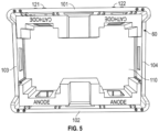
- the basket 60 has first, second, third, and fourth side walls 101, 102, 103, 104 coupled to a bottom wall 110, and extension members 121, 122.
- the first and second side walls 101, 102 are coupled to and between the third and fourth side walls 103, 104 and extend parallel to one another.
- the first side wall 101 includes first and second apertures 131, 132 (shown in FIG. 7 ) extending therethrough.
- the basket 60 holds the battery cell 30 therein such that a first electrode 121 thereof points toward the first side wall 101, and a second electrode 322 thereof points toward the second side wall 102.
- the basket 60 holds the battery cell 32 therein such that a first electrode 421 thereof points toward the first side wall 101, and a second electrode 422 thereof points toward the second side wall 102.
- the first, second, third, and fourth side walls 101, 102, 103, 104, and the bottom wall 110 are constructed of plastic.
- the extension members 121, 122 are coupled to and extend outwardly from the first side wall 101.
- the structure of the extension members 121, 122 are identical so that only the structure of extension member 121 will be discussed in greater detail herein. Also, the attachment of the extension members 121, 122 to the basket 60 are performed in a similar manner so only the attachment of the extension member 121 will be discussed herein.
- the extension member 121 includes a coupling wall 140 and first and second leg members 141, 142 coupled to and extending from the coupling wall 140 in a first direction.
- the first leg member 141 has an inner surface 150 defining a ledge 151 that is parallel to the coupling wall 140 and spaced apart from the coupling wall 140.
- the second leg member 142 has an inner surface 160 defining a ledge 161 that is parallel to the coupling wall 140 and spaced apart from the coupling wall 140.
- the extension member 121 is constructed of plastic. Referring to FIGS.
- the coupling wall 140 is disposed against an inner surface of the first side wall 101 of the basket 60 such that the first and second leg members 141, 142 extend through the first and second apertures 131, 132, respectively, of the first side wall 101, and the ledges 151, 161 are disposed against an outer surface of the first side wall 101.
- the transport device 70 is provided to hold the basket 60 thereon and to move the basket 60 in a first direction toward the first and second vertical members 81, 82.
- the transport device 70 has a first side 241 and a second side 242.
- the first direction is parallel to the first and second side walls 101, 102 of the basket 60 and parallel to the first and second sides 241, 242.
- the transport device 70 is a conveyor system.
- the first and second vertical members 81, 82 are disposed proximate to the first and second sides 241, 242, respectively, of the transport device 70.
- a horizontal top member 83 is coupled to and between a top end of the first vertical member 81 and a top end of the second vertical member 82.
- the first vertical member 81 has a slot 260 extending therein.
- the transport device 70 moves the basket 60 such that the first and second extension members 121, 122 move through the slot 260 in the first vertical member 81 and the basket 60 moves past the first and second vertical members 81, 82.
- the basket 60 has the desired position (shown in FIG. 2 ) on the transport device 70 when the first side wall 101 and the extension members 121, 122 of the basket 60 are proximate to the first side 241 of the transport device 70.
- the extension members 121, 122 on the basket 60 contact the second vertical member 82 such that the basket 60 is prevented from moving past the first and second vertical members 81, 82.
- the basket 60 is in the undesired position (shown in FIG. 1 ) on the transport device 70 when the first side wall 101 and the extension members 121, 122 of the basket 60 are disposed proximate to the second side 242 of the transport device 70.
- the battery cell 30 includes a battery housing 300, a first electrode 321, and a second electrode 322.
- the first and second electrodes 321, 322 are disposed on first and second ends 301, 302, respectively of the battery housing 300.
- the battery cell 32 includes a battery housing 400, a first electrode 421, and a second electrode 422.
- the first and second electrodes 421, 422 are disposed on first and second ends 401, 402, respectively of the battery housing 400.
- FIGS. 1, 2 , 11 and 12 a flowchart of a method for transporting the battery cell 30 will be explained in accordance with another exemplary embodiment.
- the battery cell 30 and the extension member 121 will be described in the following method.
- a user provides a battery cell 30 having a battery housing 300, a first electrode 321, and a second electrode 322.
- the first and second electrodes 321, 322 are disposed on first and second ends 301, 302, respectively of the battery housing 300.
- the user provides a basket 60 having first, second, third, and fourth side walls 101, 102, 103, 104 coupled to a bottom wall 110, and an extension member 121.
- the first and second side walls 101, 102 are coupled to and between the third and fourth side walls 103, 104 and extend parallel to one another.
- the extension member 121 is coupled to and extends outwardly from the first side wall 101.
- the user provides a transport device 70
- the user provides first and second vertical members 81, 82 disposed proximate to first and second sides 241, 242, respectively, of the transport device 70.
- the user disposes the battery cell 30 in the basket 60 such that the first electrode 321 is pointing toward the first side wall 101, and the second electrode 322 is pointing toward the second side wall 102.
- the user disposes the basket 60 on the transport device 70 in an undesired position (shown in FIG. 1 ) such that the transport device 70 holds the basket 60 thereon and moves the basket 60 in a first direction.
- the first direction is parallel to the first and second side walls 101, 102.
- the basket 60 is in the undesired position (shown in FIG. 1 ) when the first side wall 101 and the extension member 121 of the basket 60 are proximate to the second side 242 of the transport device 70.
- the transport device 70 moves the basket 60 in the first direction such that the extension member 121 on the basket 60 contacts the second vertical member 82 when the basket 60 is in the undesired position on the transport device 70 and the basket 60 is prevented from moving past the first and second vertical members 81, 82.
- the user disposes the basket 60 on the transport device 70 in a desired position (shown in FIG. 2 ) such that the transport device 70 holds the basket 60 thereon and moves the basket 60 in the first direction.
- the basket 60 is in the desired position (shown in FIG. 2 ) when the first side wall 101 and the extension member 121 of the basket 60 are disposed proximate to the first side of the transport device 70.
- the transport device 70 moves the basket 60 in the first direction such that the extension member 121 on the basket 60 moves through a slot 260 in the first vertical member 81 and the basket 60 is allowed to move past the first and second vertical members 81, 82 when the basket 60 is in the desired position on the transport device 70.
- the battery cell transport system 20 and associated method provide a substantial advantage over other systems and methods.
- the system 20 prevents the basket 60 from moving past the first and second vertical members 81, 82 when the basket 60 is placed in an undesired position on the transport device 70 (and as a result the battery cells 30, 32 which are in an improper position relative to the transport device 70 do not advance to a subsequent welding process).
Landscapes
- Chemical & Material Sciences (AREA)
- Chemical Kinetics & Catalysis (AREA)
- Electrochemistry (AREA)
- General Chemical & Material Sciences (AREA)
- Engineering & Computer Science (AREA)
- Manufacturing & Machinery (AREA)
- Mechanical Engineering (AREA)
- Battery Mounting, Suspending (AREA)
- Apparatus Associated With Microorganisms And Enzymes (AREA)
- Details Of Rigid Or Semi-Rigid Containers (AREA)
- Special Conveying (AREA)
- Non-Mechanical Conveyors (AREA)
- Secondary Cells (AREA)
Abstract
Description
- During a battery pack manufacturing process, the inventors herein have recognized that an operational position of a basket holding battery cells needs to be validated during movement of the basket to ensure the proper position/orientation of the basket on a transport device.
- In particular, the inventors herein have recognized a need for a battery cell transport system that prevents baskets from advancing past a particular position when the baskets have an undesired position/orientation on a transport device.
- A battery cell transport system for a battery cell in accordance with an exemplary embodiment is provided. The battery cell has a battery housing, a first electrode, and a second electrode. The first and second electrodes are disposed on first and second ends, respectively of the battery housing. The battery cell transport system includes a basket having first, second, third, and fourth side walls coupled to a bottom wall, and an extension member. The first and second side walls are coupled to and between the third and fourth side walls and extend parallel to one another. The extension member is coupled to and extends outwardly from the first side wall. The basket holds the battery cell therein such that the first electrode is pointing toward the first side wall, and the second electrode is pointing toward the second side wall. The battery cell transport system further includes a transport device that holds the basket thereon and moves the basket in a first direction. The first direction is parallel to the first and second side walls. The battery cell transport system further includes first and second vertical members disposed proximate to first and second sides, respectively, of the transport device. The extension member on the basket contacts the second vertical member when the basket is in an undesired position on the transport device such that the basket is prevented from moving past the first and second vertical members.
- A method for transporting a battery cell in accordance with another exemplary embodiment is provided. The battery cell has a battery housing, a first electrode, and a second electrode. The first and second electrodes are disposed on first and second ends, respectively of the battery housing. The method includes providing a basket having first, second, third, and fourth side walls coupled to a bottom wall, and an extension member. The first and second side walls are coupled to and between the third and fourth side walls and extend parallel to one another. The extension member is coupled to and extend outwardly from the first side wall. The method further includes providing a transport device for moving the basket. The method further includes providing first and second vertical members disposed proximate to first and second sides, respectively, of the transport device. The method further includes disposing the battery cell in the basket such that the first electrode is pointing toward the first side wall, and the second electrode is pointing toward the second side wall. The method further includes disposing the basket on the transport device in an undesired position. The method further includes moving the basket in a first direction utilizing the transport device such that the extension member on the basket contacts the second vertical member when the basket is in the undesired position on the transport device and the basket is prevented from moving past the first and second vertical members. The first direction is parallel to the first and second side walls.
-
-
FIG. 1 is a simplified schematic of a battery cell transport system for transporting battery cells in accordance with an exemplary embodiment wherein a basket holding the battery cells has an undesired position on a transport device; -
FIG. 2 is another simplified schematic of the battery cell transport system ofFIG. 1 wherein the basket holding battery cells has a desired position on a transport device; -
FIG. 3 is a schematic illustrating first and second vertical members, a horizontal top member, a transport device, at least one basket utilized in the battery cell transport system ofFIG. 1 ; -
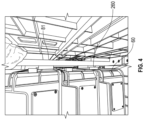
FIG. 4 is an enlarged view of a portion of the first vertical member having a slot therein, and at least one basket ofFIG. 3 ; -
FIG. 5 is a top view of a basket utilized in the battery cell transport system ofFIG. 1 ; -
FIG. 6 is a top view of a portion of a first side wall of the basket ofFIG. 5 ; -
FIG. 7 is a side view of a portion of the first side wall of the basket ofFIG. 5 ; -
FIG. 8 is a perspective view of a portion of the first side wall of the basket ofFIG. 6 ; -
FIG. 9 is an isometric view of an extension portion of the basket ofFIG. 5 ; -
FIG. 10 is a top view of the extension portion ofFIG. 9 ; and -
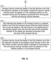
FIGS. 11 and12 are flowcharts of a method for transporting a battery cell in accordance with another exemplary embodiment. - Referring to
FIGS. 1-10 , a batterycell transport system 20 for transportingbattery cells - The battery
cell transport system 20 includes abasket 60, atransport device 70, a firstvertical member 81, a secondvertical member 82, and a horizontal top member 83 (shown inFIG. 3 ). An advantage of thesystem 20 is that thesystem 20 prevents thebasket 60 from moving past the first and secondvertical members basket 60 is placed in an undesired position (shown inFIG. 1 ) on the transport device 70 (and as a result thebattery cells transport device 70 do not advance to a subsequent welding process). - The term "proximate" used herein means within 0-1 foot in distance.
- Referring to
FIGS. 1 and5-8 , thebasket 60 is provided to hold thebattery cells basket 60 has first, second, third, andfourth side walls bottom wall 110, andextension members second side walls fourth side walls first side wall 101 includes first andsecond apertures 131, 132 (shown inFIG. 7 ) extending therethrough. Thebasket 60 holds thebattery cell 30 therein such that afirst electrode 121 thereof points toward thefirst side wall 101, and asecond electrode 322 thereof points toward thesecond side wall 102. Further, thebasket 60 holds thebattery cell 32 therein such that afirst electrode 421 thereof points toward thefirst side wall 101, and asecond electrode 422 thereof points toward thesecond side wall 102. In an exemplary embodiment, the first, second, third, andfourth side walls bottom wall 110 are constructed of plastic. - Referring to
FIGS. 5-8 , theextension members first side wall 101. The structure of theextension members extension member 121 will be discussed in greater detail herein. Also, the attachment of theextension members basket 60 are performed in a similar manner so only the attachment of theextension member 121 will be discussed herein. - Referring to
FIGS. 7 ,9 and10 , theextension member 121 includes acoupling wall 140 and first andsecond leg members coupling wall 140 in a first direction. Thefirst leg member 141 has aninner surface 150 defining aledge 151 that is parallel to thecoupling wall 140 and spaced apart from thecoupling wall 140. Also, thesecond leg member 142 has aninner surface 160 defining aledge 161 that is parallel to thecoupling wall 140 and spaced apart from thecoupling wall 140. In an exemplary embodiment, theextension member 121 is constructed of plastic. Referring toFIGS. 7 and10 , thecoupling wall 140 is disposed against an inner surface of thefirst side wall 101 of thebasket 60 such that the first andsecond leg members second apertures first side wall 101, and theledges first side wall 101. - Referring to
FIGS. 1-4 , thetransport device 70 is provided to hold thebasket 60 thereon and to move thebasket 60 in a first direction toward the first and secondvertical members transport device 70 has afirst side 241 and asecond side 242. The first direction is parallel to the first andsecond side walls basket 60 and parallel to the first andsecond sides transport device 70 is a conveyor system. - Referring to
FIGS. 1 ,3 and4 , the first and secondvertical members second sides transport device 70. A horizontaltop member 83 is coupled to and between a top end of the firstvertical member 81 and a top end of the secondvertical member 82. The firstvertical member 81 has aslot 260 extending therein. - When the
basket 60 has a desired position/placement (shown inFIG. 2 ) on thetransport device 70, thetransport device 70 moves thebasket 60 such that the first andsecond extension members slot 260 in the firstvertical member 81 and thebasket 60 moves past the first and secondvertical members basket 60 has the desired position (shown inFIG. 2 ) on thetransport device 70 when thefirst side wall 101 and theextension members basket 60 are proximate to thefirst side 241 of thetransport device 70. - Alternately, when the basket is in an undesired position/placement (shown in
FIG. 1 ) on thetransport device 70, theextension members basket 60 contact the secondvertical member 82 such that thebasket 60 is prevented from moving past the first and secondvertical members basket 60 is in the undesired position (shown inFIG. 1 ) on thetransport device 70 when thefirst side wall 101 and theextension members basket 60 are disposed proximate to thesecond side 242 of thetransport device 70. - Referring to
FIG. 1 , thebattery cell 30 includes abattery housing 300, afirst electrode 321, and asecond electrode 322. The first andsecond electrodes battery housing 300. Further, thebattery cell 32 includes abattery housing 400, afirst electrode 421, and asecond electrode 422. The first andsecond electrodes battery housing 400. - Referring to
FIGS. 1, 2 ,11 and12 , a flowchart of a method for transporting thebattery cell 30 will be explained in accordance with another exemplary embodiment. For purposes of simplicity, thebattery cell 30 and theextension member 121 will be described in the following method. - At
step 500, a user provides abattery cell 30 having abattery housing 300, afirst electrode 321, and asecond electrode 322. The first andsecond electrodes battery housing 300. - At
step 502, the user provides abasket 60 having first, second, third, andfourth side walls bottom wall 110, and anextension member 121. The first andsecond side walls fourth side walls extension member 121 is coupled to and extends outwardly from thefirst side wall 101. - At
step 504, the user provides atransport device 70 - At
step 506, the user provides first and secondvertical members second sides transport device 70. - At
step 508, the user disposes thebattery cell 30 in thebasket 60 such that thefirst electrode 321 is pointing toward thefirst side wall 101, and thesecond electrode 322 is pointing toward thesecond side wall 102. - At
step 510, the user disposes thebasket 60 on thetransport device 70 in an undesired position (shown inFIG. 1 ) such that thetransport device 70 holds thebasket 60 thereon and moves thebasket 60 in a first direction. The first direction is parallel to the first andsecond side walls basket 60 is in the undesired position (shown inFIG. 1 ) when thefirst side wall 101 and theextension member 121 of thebasket 60 are proximate to thesecond side 242 of thetransport device 70. - At
step 512, thetransport device 70 moves thebasket 60 in the first direction such that theextension member 121 on thebasket 60 contacts the secondvertical member 82 when thebasket 60 is in the undesired position on thetransport device 70 and thebasket 60 is prevented from moving past the first and secondvertical members - At
step 514, the user disposes thebasket 60 on thetransport device 70 in a desired position (shown inFIG. 2 ) such that thetransport device 70 holds thebasket 60 thereon and moves thebasket 60 in the first direction. Thebasket 60 is in the desired position (shown inFIG. 2 ) when thefirst side wall 101 and theextension member 121 of thebasket 60 are disposed proximate to the first side of thetransport device 70. - At
step 516, thetransport device 70 moves thebasket 60 in the first direction such that theextension member 121 on thebasket 60 moves through aslot 260 in the firstvertical member 81 and thebasket 60 is allowed to move past the first and secondvertical members basket 60 is in the desired position on thetransport device 70. - The battery
cell transport system 20 and associated method provide a substantial advantage over other systems and methods. In particular, thesystem 20 prevents thebasket 60 from moving past the first and secondvertical members basket 60 is placed in an undesired position on the transport device 70 (and as a result thebattery cells transport device 70 do not advance to a subsequent welding process). - While the claimed invention has been described in detail in connection with only a limited number of embodiments, it should be readily understood that the invention is not limited to such disclosed embodiments. Rather, the claimed invention can be modified to incorporate any number of variations, alterations, substitutions or equivalent arrangements not heretofore described, but which are commensurate with the spirit and scope of the invention. Additionally, while various embodiments of the claimed invention have been described, it is to be understood that aspects of the invention may include only some of the described embodiments. Accordingly, the claimed invention is not to be seen as limited by the foregoing description.
Claims (10)
- A battery cell transport system for a battery cell, the battery cell having a battery housing, a first electrode, and a second electrode; the first and second electrodes being disposed on first and second ends, respectively of the battery housing, comprising:a basket having first, second, third, and fourth side walls coupled to a bottom wall, and an extension member; the first and second side walls being coupled to and between the third and fourth side walls and extending parallel to one another; the extension member being coupled to and extending outwardly from the first side wall; the basket holding the battery cell therein such that the first electrode is pointing toward the first side wall, and the second electrode is pointing toward the second side wall;a transport device that holds the basket thereon and moves the basket in a first direction, the first direction being parallel to the first and second side walls;first and second vertical members disposed proximate to first and second sides, respectively, of the transport device, the extension member on the basket contacting the second vertical member when the basket is in an undesired position on the transport device such that the basket is prevented from moving past the first and second vertical members.
- The battery cell transport system of claim 1, wherein:
the extension member on the basket moves through a slot in the first vertical member when the basket is in a desired position on the transport device such that the basket is allowed to move past the first and second vertical members. - The battery cell transport system of claim 2, wherein:
the basket is in the desired position on the transport device when the first side wall and the extension member of the basket are proximate to the first side of the transport device. - The battery cell transport system of claim 1, wherein:
the basket is in the undesired position on the transport device when the first side wall and the extension member of the basket are disposed proximate to the second side of the transport device. - The battery cell transport system of claim 1, further comprising:
a horizontal top member coupled to and between a top end of the first vertical member and a top end of the second vertical member. - The battery cell transport system of claim 1, wherein the first side wall of the basket has first and second apertures disposed therethrough.
- The battery cell transport system of claim 1, wherein:the extension member having a coupling wall and first and second leg members coupled to and extending from the coupling wall in a first direction;the first leg member having a first inner surface defining a first ledge; andthe second leg member having a second inner surface defining a second ledge.
- The battery cell transport system of claim 7, wherein:
the coupling wall is disposed against an inner surface of the first side wall of the basket such that the first and second leg members extend through the first and second apertures, respectively, of the first side wall, and the first and second ledges are disposed against an outer surface of the first side wall. - A method for transporting a battery cell, the battery cell having a battery housing, a first electrode, and a second electrode; the first and second electrodes being disposed on first and second ends, respectively of the battery housing, the method comprising:providing a basket having first, second, third, and fourth side walls coupled to a bottom wall, and an extension member; the first and second side walls being coupled to and between the third and fourth side walls and extending parallel to one another; the extension member being coupled to and extending outwardly from the first side wall;providing a transport device for moving the basket;providing first and second vertical members disposed proximate to first and second sides, respectively, of the transport device;disposing the battery cell in the basket such that the first electrode is pointing toward the first side wall, and the second electrode is pointing toward the second side wall;disposing the basket on the transport device in an undesired position; andmoving the basket in a first direction utilizing the transport device such that the extension member on the basket contacts the second vertical member when the basket is in the undesired position on the transport device and the basket is prevented from moving past the first and second vertical members, the first direction being parallel to the first and second side walls.
- The method of claim 9, further comprising:disposing the basket on the transport device in a desired position; andmoving the basket in the first direction utilizing the transport device such that the extension member on the basket moves through a slot in the first vertical member and the basket moves past the first and second vertical members when the basket is in the desired position on the transport device.
Applications Claiming Priority (2)
| Application Number | Priority Date | Filing Date | Title |
|---|---|---|---|
| US17/994,100 US12592407B2 (en) | 2022-11-25 | 2022-11-25 | Battery cell transport system for a battery cell |
| PCT/KR2023/017756 WO2024111950A1 (en) | 2022-11-25 | 2023-11-07 | Battery cell transport system for battery cell |
Publications (2)
| Publication Number | Publication Date |
|---|---|
| EP4509442A1 true EP4509442A1 (en) | 2025-02-19 |
| EP4509442A4 EP4509442A4 (en) | 2026-03-11 |
Family
ID=91191091
Family Applications (1)
| Application Number | Title | Priority Date | Filing Date |
|---|---|---|---|
| EP23894879.8A Pending EP4509442A4 (en) | 2022-11-25 | 2023-11-07 | BATTERY CELL TRANSPORT SYSTEM FOR ONE BATTERY CELL |
Country Status (6)
| Country | Link |
|---|---|
| US (1) | US12592407B2 (en) |
| EP (1) | EP4509442A4 (en) |
| JP (1) | JP7820028B2 (en) |
| KR (1) | KR102941251B1 (en) |
| CN (1) | CN119384384A (en) |
| WO (1) | WO2024111950A1 (en) |
Families Citing this family (1)
| Publication number | Priority date | Publication date | Assignee | Title |
|---|---|---|---|---|
| US12430962B2 (en) * | 2023-11-30 | 2025-09-30 | Toyota Motor Engineering & Manufacturing North America, Inc. | Battery life prediction using a global-local decomposition transformer |
Family Cites Families (18)
| Publication number | Priority date | Publication date | Assignee | Title |
|---|---|---|---|---|
| JPH05112388A (en) | 1991-10-11 | 1993-05-07 | Mita Ind Co Ltd | Positioning of partition, container and partition |
| JPH0649429U (en) | 1992-11-26 | 1994-07-08 | 太平洋工業株式会社 | Belt conveyor article stopping device |
| JPH07179219A (en) | 1993-12-24 | 1995-07-18 | Ntn Corp | Vibratory parts supply machine |
| JPH0739847U (en) | 1993-12-27 | 1995-07-18 | オリンパス光学工業株式会社 | Endotracheal tube insertion aid |
| JPH0812049A (en) | 1994-06-24 | 1996-01-16 | Toshiba Corp | Parts transfer device and parts transfer method |
| JP3576213B2 (en) | 1994-07-28 | 2004-10-13 | 東芝電池株式会社 | Battery transport carrier forward / reverse detection method and battery transport carrier forward / reverse detection device |
| JPH10139045A (en) | 1996-11-11 | 1998-05-26 | Fuji Photo Film Co Ltd | Container for carriage |
| EP2894026B1 (en) | 2014-01-13 | 2018-04-18 | HADI Offermann Maschinenbau GmbH | Welding machine for the production of batteries and method for the production of batteries by means of a welding machine |
| KR101937995B1 (en) | 2015-06-04 | 2019-01-11 | 주식회사 엘지화학 | Test Device for function of Battery Pack |
| KR102490868B1 (en) * | 2015-11-09 | 2023-01-20 | 삼성에스디아이 주식회사 | Battery rack |
| KR101973741B1 (en) | 2017-07-17 | 2019-04-30 | 에스케이이노베이션 주식회사 | Battery Cell Common Tray |
| CN109175679B (en) | 2018-10-29 | 2024-09-27 | 武汉逸飞激光智能装备有限公司 | Welding system |
| US11427408B2 (en) | 2018-11-06 | 2022-08-30 | B & B Metals, Inc. | Tie plate dispenser and method therefore |
| JP6741308B2 (en) * | 2019-01-25 | 2020-08-19 | 株式会社ソフトエナジーコントロールズ | Rechargeable battery transport tray |
| KR102425700B1 (en) | 2019-06-10 | 2022-07-28 | 삼성에스디아이 주식회사 | Tray for packing secondary battery |
| KR102746536B1 (en) | 2019-10-08 | 2024-12-23 | 주식회사 엘지에너지솔루션 | Apparatus for transporting battery |
| CN213504086U (en) | 2020-08-14 | 2021-06-22 | 包头钢铁(集团)有限责任公司 | Coke oven machine side tail coke loading and unloading box capable of being pulled and transported by forklift |
| KR102523082B1 (en) | 2020-09-22 | 2023-04-18 | 한국앤컴퍼니 주식회사 | Lead-acid battery damage prevention case device to prevent scratches and product damage caused by collisions between stoppers and products during conveyor transfer |
-
2022
- 2022-11-25 US US17/994,100 patent/US12592407B2/en active Active
-
2023
- 2023-11-07 JP JP2024569397A patent/JP7820028B2/en active Active
- 2023-11-07 CN CN202380046464.3A patent/CN119384384A/en active Pending
- 2023-11-07 KR KR1020247037265A patent/KR102941251B1/en active Active
- 2023-11-07 EP EP23894879.8A patent/EP4509442A4/en active Pending
- 2023-11-07 WO PCT/KR2023/017756 patent/WO2024111950A1/en not_active Ceased
Also Published As
| Publication number | Publication date |
|---|---|
| KR20250003741A (en) | 2025-01-07 |
| JP2025519128A (en) | 2025-06-24 |
| EP4509442A4 (en) | 2026-03-11 |
| KR102941251B1 (en) | 2026-03-18 |
| CN119384384A (en) | 2025-01-28 |
| US12592407B2 (en) | 2026-03-31 |
| WO2024111950A1 (en) | 2024-05-30 |
| JP7820028B2 (en) | 2026-02-25 |
| US20240178501A1 (en) | 2024-05-30 |
Similar Documents
| Publication | Publication Date | Title |
|---|---|---|
| KR102553642B1 (en) | Piercing unit, Piercing apparatus including the same and Apparatus for manufacturing pouch type secondary battery including the same | |
| US10141697B2 (en) | Electrical connector | |
| EP2843725B1 (en) | Battery Pack | |
| KR102498389B1 (en) | Containment system for battery modules | |
| US12592407B2 (en) | Battery cell transport system for a battery cell | |
| US8747120B2 (en) | Electrical connector incorporated with pick-and-place pick-up cap | |
| US20250136388A1 (en) | Cell Packaging Device | |
| US8916286B2 (en) | Battery pack | |
| US11652231B2 (en) | Secondary battery cell supply apparatus for process of folding secondary battery cell | |
| KR20130014334A (en) | Rechargeable battery | |
| US20200105632A1 (en) | Wafer accommodation container | |
| KR102367412B1 (en) | Secondary battery cross-transfer equipment | |
| US20230048828A1 (en) | Rolling Device for Secondary Battery | |
| JPH0519187U (en) | Carrier for semiconductor package | |
| KR102665857B1 (en) | Cell guide for secondary cell and cell tray having the same | |
| KR20200069883A (en) | Apparatus for stacking of system for producing electrodes of battery and method for stacking producing electrodes of battery | |
| CN223230498U (en) | Electrode protection structure and cell module | |
| US20230158701A1 (en) | Electrode Cutting Device and Method and Electrode Manufacturing Apparatus Comprising the Same | |
| TW201740500A (en) | Container support rack support body having two front support parts, a rear support part, an indent part and an extension part | |
| US10985517B2 (en) | Apparatus for assembling cases made of thin plate | |
| JP2017147043A (en) | Stacking pallet transfer device | |
| EP3579265B1 (en) | Substrate housing container | |
| KR20250132291A (en) | Device carring battery cells | |
| US20240322388A1 (en) | Battery pack | |
| KR20210123574A (en) | Secondary Battery Cell Manufacturing Apparatus And Method Using The Same |
Legal Events
| Date | Code | Title | Description |
|---|---|---|---|
| STAA | Information on the status of an ep patent application or granted ep patent |
Free format text: STATUS: THE INTERNATIONAL PUBLICATION HAS BEEN MADE |
|
| PUAI | Public reference made under article 153(3) epc to a published international application that has entered the european phase |
Free format text: ORIGINAL CODE: 0009012 |
|
| STAA | Information on the status of an ep patent application or granted ep patent |
Free format text: STATUS: REQUEST FOR EXAMINATION WAS MADE |
|
| 17P | Request for examination filed |
Effective date: 20241114 |
|
| AK | Designated contracting states |
Kind code of ref document: A1 Designated state(s): AL AT BE BG CH CY CZ DE DK EE ES FI FR GB GR HR HU IE IS IT LI LT LU LV MC ME MK MT NL NO PL PT RO RS SE SI SK SM TR |
|
| DAV | Request for validation of the european patent (deleted) | ||
| DAX | Request for extension of the european patent (deleted) | ||
| A4 | Supplementary search report drawn up and despatched |
Effective date: 20260209 |
|
| RIC1 | Information provided on ipc code assigned before grant |
Ipc: B65G 47/88 20060101AFI20260203BHEP Ipc: B65D 25/20 20060101ALI20260203BHEP Ipc: H01M 50/256 20210101ALI20260203BHEP Ipc: H01M 10/04 20060101ALI20260203BHEP Ipc: H01M 50/244 20210101ALI20260203BHEP |