EP4509416A1 - Dual container, regenerated resin production method, preform, and method for extracting inner bag of dual container - Google Patents
Dual container, regenerated resin production method, preform, and method for extracting inner bag of dual container Download PDFInfo
- Publication number
- EP4509416A1 EP4509416A1 EP23788241.0A EP23788241A EP4509416A1 EP 4509416 A1 EP4509416 A1 EP 4509416A1 EP 23788241 A EP23788241 A EP 23788241A EP 4509416 A1 EP4509416 A1 EP 4509416A1
- Authority
- EP
- European Patent Office
- Prior art keywords
- inner bag
- mouth portion
- preform
- outer shell
- attachment
- Prior art date
- Legal status (The legal status is an assumption and is not a legal conclusion. Google has not performed a legal analysis and makes no representation as to the accuracy of the status listed.)
- Pending
Links
Images


































Classifications
-
- B—PERFORMING OPERATIONS; TRANSPORTING
- B65—CONVEYING; PACKING; STORING; HANDLING THIN OR FILAMENTARY MATERIAL
- B65D—CONTAINERS FOR STORAGE OR TRANSPORT OF ARTICLES OR MATERIALS, e.g. BAGS, BARRELS, BOTTLES, BOXES, CANS, CARTONS, CRATES, DRUMS, JARS, TANKS, HOPPERS, FORWARDING CONTAINERS; ACCESSORIES, CLOSURES, OR FITTINGS THEREFOR; PACKAGING ELEMENTS; PACKAGES
- B65D23/00—Details of bottles or jars not otherwise provided for
- B65D23/02—Linings or internal coatings
-
- B—PERFORMING OPERATIONS; TRANSPORTING
- B29—WORKING OF PLASTICS; WORKING OF SUBSTANCES IN A PLASTIC STATE IN GENERAL
- B29B—PREPARATION OR PRETREATMENT OF THE MATERIAL TO BE SHAPED; MAKING GRANULES OR PREFORMS; RECOVERY OF PLASTICS OR OTHER CONSTITUENTS OF WASTE MATERIAL CONTAINING PLASTICS
- B29B11/00—Making preforms
- B29B11/04—Making preforms by assembling preformed material
-
- B—PERFORMING OPERATIONS; TRANSPORTING
- B29—WORKING OF PLASTICS; WORKING OF SUBSTANCES IN A PLASTIC STATE IN GENERAL
- B29B—PREPARATION OR PRETREATMENT OF THE MATERIAL TO BE SHAPED; MAKING GRANULES OR PREFORMS; RECOVERY OF PLASTICS OR OTHER CONSTITUENTS OF WASTE MATERIAL CONTAINING PLASTICS
- B29B11/00—Making preforms
- B29B11/06—Making preforms by moulding the material
- B29B11/08—Injection moulding
-
- B—PERFORMING OPERATIONS; TRANSPORTING
- B29—WORKING OF PLASTICS; WORKING OF SUBSTANCES IN A PLASTIC STATE IN GENERAL
- B29B—PREPARATION OR PRETREATMENT OF THE MATERIAL TO BE SHAPED; MAKING GRANULES OR PREFORMS; RECOVERY OF PLASTICS OR OTHER CONSTITUENTS OF WASTE MATERIAL CONTAINING PLASTICS
- B29B11/00—Making preforms
- B29B11/06—Making preforms by moulding the material
- B29B11/10—Extrusion moulding
-
- B—PERFORMING OPERATIONS; TRANSPORTING
- B29—WORKING OF PLASTICS; WORKING OF SUBSTANCES IN A PLASTIC STATE IN GENERAL
- B29B—PREPARATION OR PRETREATMENT OF THE MATERIAL TO BE SHAPED; MAKING GRANULES OR PREFORMS; RECOVERY OF PLASTICS OR OTHER CONSTITUENTS OF WASTE MATERIAL CONTAINING PLASTICS
- B29B11/00—Making preforms
- B29B11/14—Making preforms characterised by structure or composition
-
- B—PERFORMING OPERATIONS; TRANSPORTING
- B29—WORKING OF PLASTICS; WORKING OF SUBSTANCES IN A PLASTIC STATE IN GENERAL
- B29B—PREPARATION OR PRETREATMENT OF THE MATERIAL TO BE SHAPED; MAKING GRANULES OR PREFORMS; RECOVERY OF PLASTICS OR OTHER CONSTITUENTS OF WASTE MATERIAL CONTAINING PLASTICS
- B29B17/00—Recovery of plastics or other constituents of waste material containing plastics
- B29B17/0026—Recovery of plastics or other constituents of waste material containing plastics by agglomeration or compacting
-
- B—PERFORMING OPERATIONS; TRANSPORTING
- B29—WORKING OF PLASTICS; WORKING OF SUBSTANCES IN A PLASTIC STATE IN GENERAL
- B29B—PREPARATION OR PRETREATMENT OF THE MATERIAL TO BE SHAPED; MAKING GRANULES OR PREFORMS; RECOVERY OF PLASTICS OR OTHER CONSTITUENTS OF WASTE MATERIAL CONTAINING PLASTICS
- B29B17/00—Recovery of plastics or other constituents of waste material containing plastics
- B29B17/04—Disintegrating plastics, e.g. by milling
-
- B—PERFORMING OPERATIONS; TRANSPORTING
- B29—WORKING OF PLASTICS; WORKING OF SUBSTANCES IN A PLASTIC STATE IN GENERAL
- B29C—SHAPING OR JOINING OF PLASTICS; SHAPING OF MATERIAL IN A PLASTIC STATE, NOT OTHERWISE PROVIDED FOR; AFTER-TREATMENT OF THE SHAPED PRODUCTS, e.g. REPAIRING
- B29C49/00—Blow-moulding, i.e. blowing a preform or parison to a desired shape within a mould; Apparatus therefor
- B29C49/02—Combined blow-moulding and manufacture of the preform or the parison
- B29C49/06—Injection blow-moulding
-
- B—PERFORMING OPERATIONS; TRANSPORTING
- B29—WORKING OF PLASTICS; WORKING OF SUBSTANCES IN A PLASTIC STATE IN GENERAL
- B29C—SHAPING OR JOINING OF PLASTICS; SHAPING OF MATERIAL IN A PLASTIC STATE, NOT OTHERWISE PROVIDED FOR; AFTER-TREATMENT OF THE SHAPED PRODUCTS, e.g. REPAIRING
- B29C49/00—Blow-moulding, i.e. blowing a preform or parison to a desired shape within a mould; Apparatus therefor
- B29C49/071—Preforms or parisons characterised by their configuration, e.g. geometry, dimensions or physical properties
-
- B—PERFORMING OPERATIONS; TRANSPORTING
- B29—WORKING OF PLASTICS; WORKING OF SUBSTANCES IN A PLASTIC STATE IN GENERAL
- B29C—SHAPING OR JOINING OF PLASTICS; SHAPING OF MATERIAL IN A PLASTIC STATE, NOT OTHERWISE PROVIDED FOR; AFTER-TREATMENT OF THE SHAPED PRODUCTS, e.g. REPAIRING
- B29C49/00—Blow-moulding, i.e. blowing a preform or parison to a desired shape within a mould; Apparatus therefor
- B29C49/22—Blow-moulding, i.e. blowing a preform or parison to a desired shape within a mould; Apparatus therefor using multilayered preforms or parisons
-
- B—PERFORMING OPERATIONS; TRANSPORTING
- B29—WORKING OF PLASTICS; WORKING OF SUBSTANCES IN A PLASTIC STATE IN GENERAL
- B29D—PRODUCING PARTICULAR ARTICLES FROM PLASTICS OR FROM SUBSTANCES IN A PLASTIC STATE
- B29D22/00—Producing hollow articles
- B29D22/003—Containers for packaging, storing or transporting, e.g. bottles, jars, cans, barrels, tanks
-
- B—PERFORMING OPERATIONS; TRANSPORTING
- B65—CONVEYING; PACKING; STORING; HANDLING THIN OR FILAMENTARY MATERIAL
- B65D—CONTAINERS FOR STORAGE OR TRANSPORT OF ARTICLES OR MATERIALS, e.g. BAGS, BARRELS, BOTTLES, BOXES, CANS, CARTONS, CRATES, DRUMS, JARS, TANKS, HOPPERS, FORWARDING CONTAINERS; ACCESSORIES, CLOSURES, OR FITTINGS THEREFOR; PACKAGING ELEMENTS; PACKAGES
- B65D1/00—Rigid or semi-rigid containers having bodies formed in one piece, e.g. by casting metallic material, by moulding plastics, by blowing vitreous material, by throwing ceramic material, by moulding pulped fibrous material or by deep-drawing operations performed on sheet material
- B65D1/02—Bottles or similar containers with necks or like restricted apertures, designed for pouring contents
-
- B—PERFORMING OPERATIONS; TRANSPORTING
- B65—CONVEYING; PACKING; STORING; HANDLING THIN OR FILAMENTARY MATERIAL
- B65D—CONTAINERS FOR STORAGE OR TRANSPORT OF ARTICLES OR MATERIALS, e.g. BAGS, BARRELS, BOTTLES, BOXES, CANS, CARTONS, CRATES, DRUMS, JARS, TANKS, HOPPERS, FORWARDING CONTAINERS; ACCESSORIES, CLOSURES, OR FITTINGS THEREFOR; PACKAGING ELEMENTS; PACKAGES
- B65D25/00—Details of other kinds or types of rigid or semi-rigid containers
- B65D25/14—Linings or internal coatings
- B65D25/16—Loose, or loosely-attached, linings
-
- B—PERFORMING OPERATIONS; TRANSPORTING
- B65—CONVEYING; PACKING; STORING; HANDLING THIN OR FILAMENTARY MATERIAL
- B65D—CONTAINERS FOR STORAGE OR TRANSPORT OF ARTICLES OR MATERIALS, e.g. BAGS, BARRELS, BOTTLES, BOXES, CANS, CARTONS, CRATES, DRUMS, JARS, TANKS, HOPPERS, FORWARDING CONTAINERS; ACCESSORIES, CLOSURES, OR FITTINGS THEREFOR; PACKAGING ELEMENTS; PACKAGES
- B65D41/00—Caps, e.g. crown caps or crown seals, i.e. members having parts arranged for engagement with the external periphery of a neck or wall defining a pouring opening or discharge aperture; Protective cap-like covers for closure members, e.g. decorative covers of metal foil or paper
- B65D41/02—Caps or cap-like covers without lines of weakness, tearing strips, tags, or like opening or removal devices
- B65D41/04—Threaded or like caps or cap-like covers secured by rotation
-
- B—PERFORMING OPERATIONS; TRANSPORTING
- B65—CONVEYING; PACKING; STORING; HANDLING THIN OR FILAMENTARY MATERIAL
- B65D—CONTAINERS FOR STORAGE OR TRANSPORT OF ARTICLES OR MATERIALS, e.g. BAGS, BARRELS, BOTTLES, BOXES, CANS, CARTONS, CRATES, DRUMS, JARS, TANKS, HOPPERS, FORWARDING CONTAINERS; ACCESSORIES, CLOSURES, OR FITTINGS THEREFOR; PACKAGING ELEMENTS; PACKAGES
- B65D41/00—Caps, e.g. crown caps or crown seals, i.e. members having parts arranged for engagement with the external periphery of a neck or wall defining a pouring opening or discharge aperture; Protective cap-like covers for closure members, e.g. decorative covers of metal foil or paper
- B65D41/02—Caps or cap-like covers without lines of weakness, tearing strips, tags, or like opening or removal devices
- B65D41/16—Snap-on caps or cap-like covers
-
- B—PERFORMING OPERATIONS; TRANSPORTING
- B65—CONVEYING; PACKING; STORING; HANDLING THIN OR FILAMENTARY MATERIAL
- B65D—CONTAINERS FOR STORAGE OR TRANSPORT OF ARTICLES OR MATERIALS, e.g. BAGS, BARRELS, BOTTLES, BOXES, CANS, CARTONS, CRATES, DRUMS, JARS, TANKS, HOPPERS, FORWARDING CONTAINERS; ACCESSORIES, CLOSURES, OR FITTINGS THEREFOR; PACKAGING ELEMENTS; PACKAGES
- B65D47/00—Closures with filling and discharging, or with discharging, devices
- B65D47/04—Closures with discharging devices other than pumps
- B65D47/06—Closures with discharging devices other than pumps with pouring spouts or tubes; with discharge nozzles or passages
- B65D47/10—Closures with discharging devices other than pumps with pouring spouts or tubes; with discharge nozzles or passages having frangible closures
- B65D47/103—Membranes with a tearing element
-
- B—PERFORMING OPERATIONS; TRANSPORTING
- B65—CONVEYING; PACKING; STORING; HANDLING THIN OR FILAMENTARY MATERIAL
- B65D—CONTAINERS FOR STORAGE OR TRANSPORT OF ARTICLES OR MATERIALS, e.g. BAGS, BARRELS, BOTTLES, BOXES, CANS, CARTONS, CRATES, DRUMS, JARS, TANKS, HOPPERS, FORWARDING CONTAINERS; ACCESSORIES, CLOSURES, OR FITTINGS THEREFOR; PACKAGING ELEMENTS; PACKAGES
- B65D47/00—Closures with filling and discharging, or with discharging, devices
- B65D47/04—Closures with discharging devices other than pumps
- B65D47/06—Closures with discharging devices other than pumps with pouring spouts or tubes; with discharge nozzles or passages
- B65D47/12—Closures with discharging devices other than pumps with pouring spouts or tubes; with discharge nozzles or passages having removable closures
-
- B—PERFORMING OPERATIONS; TRANSPORTING
- B65—CONVEYING; PACKING; STORING; HANDLING THIN OR FILAMENTARY MATERIAL
- B65D—CONTAINERS FOR STORAGE OR TRANSPORT OF ARTICLES OR MATERIALS, e.g. BAGS, BARRELS, BOTTLES, BOXES, CANS, CARTONS, CRATES, DRUMS, JARS, TANKS, HOPPERS, FORWARDING CONTAINERS; ACCESSORIES, CLOSURES, OR FITTINGS THEREFOR; PACKAGING ELEMENTS; PACKAGES
- B65D47/00—Closures with filling and discharging, or with discharging, devices
- B65D47/04—Closures with discharging devices other than pumps
- B65D47/06—Closures with discharging devices other than pumps with pouring spouts or tubes; with discharge nozzles or passages
- B65D47/12—Closures with discharging devices other than pumps with pouring spouts or tubes; with discharge nozzles or passages having removable closures
- B65D47/122—Threaded caps
- B65D47/123—Threaded caps with internal parts
-
- B—PERFORMING OPERATIONS; TRANSPORTING
- B65—CONVEYING; PACKING; STORING; HANDLING THIN OR FILAMENTARY MATERIAL
- B65D—CONTAINERS FOR STORAGE OR TRANSPORT OF ARTICLES OR MATERIALS, e.g. BAGS, BARRELS, BOTTLES, BOXES, CANS, CARTONS, CRATES, DRUMS, JARS, TANKS, HOPPERS, FORWARDING CONTAINERS; ACCESSORIES, CLOSURES, OR FITTINGS THEREFOR; PACKAGING ELEMENTS; PACKAGES
- B65D47/00—Closures with filling and discharging, or with discharging, devices
- B65D47/04—Closures with discharging devices other than pumps
- B65D47/06—Closures with discharging devices other than pumps with pouring spouts or tubes; with discharge nozzles or passages
- B65D47/12—Closures with discharging devices other than pumps with pouring spouts or tubes; with discharge nozzles or passages having removable closures
- B65D47/127—Snap-on caps
- B65D47/128—Snap-on caps with internal parts
-
- B—PERFORMING OPERATIONS; TRANSPORTING
- B65—CONVEYING; PACKING; STORING; HANDLING THIN OR FILAMENTARY MATERIAL
- B65D—CONTAINERS FOR STORAGE OR TRANSPORT OF ARTICLES OR MATERIALS, e.g. BAGS, BARRELS, BOTTLES, BOXES, CANS, CARTONS, CRATES, DRUMS, JARS, TANKS, HOPPERS, FORWARDING CONTAINERS; ACCESSORIES, CLOSURES, OR FITTINGS THEREFOR; PACKAGING ELEMENTS; PACKAGES
- B65D47/00—Closures with filling and discharging, or with discharging, devices
- B65D47/04—Closures with discharging devices other than pumps
- B65D47/32—Closures with discharging devices other than pumps with means for venting
-
- B—PERFORMING OPERATIONS; TRANSPORTING
- B65—CONVEYING; PACKING; STORING; HANDLING THIN OR FILAMENTARY MATERIAL
- B65D—CONTAINERS FOR STORAGE OR TRANSPORT OF ARTICLES OR MATERIALS, e.g. BAGS, BARRELS, BOTTLES, BOXES, CANS, CARTONS, CRATES, DRUMS, JARS, TANKS, HOPPERS, FORWARDING CONTAINERS; ACCESSORIES, CLOSURES, OR FITTINGS THEREFOR; PACKAGING ELEMENTS; PACKAGES
- B65D51/00—Closures not otherwise provided for
- B65D51/18—Arrangements of closures with protective outer cap-like covers or of two or more co-operating closures
-
- B—PERFORMING OPERATIONS; TRANSPORTING
- B65—CONVEYING; PACKING; STORING; HANDLING THIN OR FILAMENTARY MATERIAL
- B65D—CONTAINERS FOR STORAGE OR TRANSPORT OF ARTICLES OR MATERIALS, e.g. BAGS, BARRELS, BOTTLES, BOXES, CANS, CARTONS, CRATES, DRUMS, JARS, TANKS, HOPPERS, FORWARDING CONTAINERS; ACCESSORIES, CLOSURES, OR FITTINGS THEREFOR; PACKAGING ELEMENTS; PACKAGES
- B65D51/00—Closures not otherwise provided for
- B65D51/24—Closures not otherwise provided for combined or co-operating with auxiliary devices for non-closing purposes
- B65D51/242—Closures not otherwise provided for combined or co-operating with auxiliary devices for non-closing purposes provided with means for facilitating lifting or suspending of the container
-
- B—PERFORMING OPERATIONS; TRANSPORTING
- B65—CONVEYING; PACKING; STORING; HANDLING THIN OR FILAMENTARY MATERIAL
- B65D—CONTAINERS FOR STORAGE OR TRANSPORT OF ARTICLES OR MATERIALS, e.g. BAGS, BARRELS, BOTTLES, BOXES, CANS, CARTONS, CRATES, DRUMS, JARS, TANKS, HOPPERS, FORWARDING CONTAINERS; ACCESSORIES, CLOSURES, OR FITTINGS THEREFOR; PACKAGING ELEMENTS; PACKAGES
- B65D77/00—Packages formed by enclosing articles or materials in preformed containers, e.g. boxes, cartons, sacks or bags
- B65D77/04—Articles or materials enclosed in two or more containers disposed one within another
-
- B—PERFORMING OPERATIONS; TRANSPORTING
- B65—CONVEYING; PACKING; STORING; HANDLING THIN OR FILAMENTARY MATERIAL
- B65D—CONTAINERS FOR STORAGE OR TRANSPORT OF ARTICLES OR MATERIALS, e.g. BAGS, BARRELS, BOTTLES, BOXES, CANS, CARTONS, CRATES, DRUMS, JARS, TANKS, HOPPERS, FORWARDING CONTAINERS; ACCESSORIES, CLOSURES, OR FITTINGS THEREFOR; PACKAGING ELEMENTS; PACKAGES
- B65D77/00—Packages formed by enclosing articles or materials in preformed containers, e.g. boxes, cartons, sacks or bags
- B65D77/04—Articles or materials enclosed in two or more containers disposed one within another
- B65D77/06—Liquids or semi-liquids or other materials or articles enclosed in flexible containers disposed within rigid containers
-
- B—PERFORMING OPERATIONS; TRANSPORTING
- B29—WORKING OF PLASTICS; WORKING OF SUBSTANCES IN A PLASTIC STATE IN GENERAL
- B29B—PREPARATION OR PRETREATMENT OF THE MATERIAL TO BE SHAPED; MAKING GRANULES OR PREFORMS; RECOVERY OF PLASTICS OR OTHER CONSTITUENTS OF WASTE MATERIAL CONTAINING PLASTICS
- B29B17/00—Recovery of plastics or other constituents of waste material containing plastics
- B29B17/02—Separating plastics from other materials
-
- B—PERFORMING OPERATIONS; TRANSPORTING
- B29—WORKING OF PLASTICS; WORKING OF SUBSTANCES IN A PLASTIC STATE IN GENERAL
- B29B—PREPARATION OR PRETREATMENT OF THE MATERIAL TO BE SHAPED; MAKING GRANULES OR PREFORMS; RECOVERY OF PLASTICS OR OTHER CONSTITUENTS OF WASTE MATERIAL CONTAINING PLASTICS
- B29B17/00—Recovery of plastics or other constituents of waste material containing plastics
- B29B2017/0089—Recycling systems, wherein the flow of products between producers, sellers and consumers includes at least a recycling step, e.g. the products being fed back to the sellers or to the producers for recycling purposes
-
- B—PERFORMING OPERATIONS; TRANSPORTING
- B29—WORKING OF PLASTICS; WORKING OF SUBSTANCES IN A PLASTIC STATE IN GENERAL
- B29B—PREPARATION OR PRETREATMENT OF THE MATERIAL TO BE SHAPED; MAKING GRANULES OR PREFORMS; RECOVERY OF PLASTICS OR OTHER CONSTITUENTS OF WASTE MATERIAL CONTAINING PLASTICS
- B29B17/00—Recovery of plastics or other constituents of waste material containing plastics
- B29B17/02—Separating plastics from other materials
- B29B2017/0203—Separating plastics from plastics
-
- B—PERFORMING OPERATIONS; TRANSPORTING
- B29—WORKING OF PLASTICS; WORKING OF SUBSTANCES IN A PLASTIC STATE IN GENERAL
- B29C—SHAPING OR JOINING OF PLASTICS; SHAPING OF MATERIAL IN A PLASTIC STATE, NOT OTHERWISE PROVIDED FOR; AFTER-TREATMENT OF THE SHAPED PRODUCTS, e.g. REPAIRING
- B29C49/00—Blow-moulding, i.e. blowing a preform or parison to a desired shape within a mould; Apparatus therefor
- B29C49/02—Combined blow-moulding and manufacture of the preform or the parison
- B29C2049/023—Combined blow-moulding and manufacture of the preform or the parison using inherent heat of the preform, i.e. 1 step blow moulding
-
- B—PERFORMING OPERATIONS; TRANSPORTING
- B29—WORKING OF PLASTICS; WORKING OF SUBSTANCES IN A PLASTIC STATE IN GENERAL
- B29C—SHAPING OR JOINING OF PLASTICS; SHAPING OF MATERIAL IN A PLASTIC STATE, NOT OTHERWISE PROVIDED FOR; AFTER-TREATMENT OF THE SHAPED PRODUCTS, e.g. REPAIRING
- B29C2949/00—Indexing scheme relating to blow-moulding
- B29C2949/07—Preforms or parisons characterised by their configuration
- B29C2949/0715—Preforms or parisons characterised by their configuration the preform having one end closed
-
- B—PERFORMING OPERATIONS; TRANSPORTING
- B29—WORKING OF PLASTICS; WORKING OF SUBSTANCES IN A PLASTIC STATE IN GENERAL
- B29C—SHAPING OR JOINING OF PLASTICS; SHAPING OF MATERIAL IN A PLASTIC STATE, NOT OTHERWISE PROVIDED FOR; AFTER-TREATMENT OF THE SHAPED PRODUCTS, e.g. REPAIRING
- B29C2949/00—Indexing scheme relating to blow-moulding
- B29C2949/07—Preforms or parisons characterised by their configuration
- B29C2949/079—Auxiliary parts or inserts
- B29C2949/0791—Handle
-
- B—PERFORMING OPERATIONS; TRANSPORTING
- B29—WORKING OF PLASTICS; WORKING OF SUBSTANCES IN A PLASTIC STATE IN GENERAL
- B29C—SHAPING OR JOINING OF PLASTICS; SHAPING OF MATERIAL IN A PLASTIC STATE, NOT OTHERWISE PROVIDED FOR; AFTER-TREATMENT OF THE SHAPED PRODUCTS, e.g. REPAIRING
- B29C2949/00—Indexing scheme relating to blow-moulding
- B29C2949/07—Preforms or parisons characterised by their configuration
- B29C2949/079—Auxiliary parts or inserts
- B29C2949/0792—Closure
-
- B—PERFORMING OPERATIONS; TRANSPORTING
- B29—WORKING OF PLASTICS; WORKING OF SUBSTANCES IN A PLASTIC STATE IN GENERAL
- B29C—SHAPING OR JOINING OF PLASTICS; SHAPING OF MATERIAL IN A PLASTIC STATE, NOT OTHERWISE PROVIDED FOR; AFTER-TREATMENT OF THE SHAPED PRODUCTS, e.g. REPAIRING
- B29C2949/00—Indexing scheme relating to blow-moulding
- B29C2949/07—Preforms or parisons characterised by their configuration
- B29C2949/079—Auxiliary parts or inserts
- B29C2949/0793—Transport means
-
- B—PERFORMING OPERATIONS; TRANSPORTING
- B29—WORKING OF PLASTICS; WORKING OF SUBSTANCES IN A PLASTIC STATE IN GENERAL
- B29C—SHAPING OR JOINING OF PLASTICS; SHAPING OF MATERIAL IN A PLASTIC STATE, NOT OTHERWISE PROVIDED FOR; AFTER-TREATMENT OF THE SHAPED PRODUCTS, e.g. REPAIRING
- B29C2949/00—Indexing scheme relating to blow-moulding
- B29C2949/30—Preforms or parisons made of several components
- B29C2949/3008—Preforms or parisons made of several components at neck portion
-
- B—PERFORMING OPERATIONS; TRANSPORTING
- B29—WORKING OF PLASTICS; WORKING OF SUBSTANCES IN A PLASTIC STATE IN GENERAL
- B29C—SHAPING OR JOINING OF PLASTICS; SHAPING OF MATERIAL IN A PLASTIC STATE, NOT OTHERWISE PROVIDED FOR; AFTER-TREATMENT OF THE SHAPED PRODUCTS, e.g. REPAIRING
- B29C2949/00—Indexing scheme relating to blow-moulding
- B29C2949/30—Preforms or parisons made of several components
- B29C2949/3012—Preforms or parisons made of several components at flange portion
-
- B—PERFORMING OPERATIONS; TRANSPORTING
- B29—WORKING OF PLASTICS; WORKING OF SUBSTANCES IN A PLASTIC STATE IN GENERAL
- B29C—SHAPING OR JOINING OF PLASTICS; SHAPING OF MATERIAL IN A PLASTIC STATE, NOT OTHERWISE PROVIDED FOR; AFTER-TREATMENT OF THE SHAPED PRODUCTS, e.g. REPAIRING
- B29C2949/00—Indexing scheme relating to blow-moulding
- B29C2949/30—Preforms or parisons made of several components
- B29C2949/3016—Preforms or parisons made of several components at body portion
-
- B—PERFORMING OPERATIONS; TRANSPORTING
- B29—WORKING OF PLASTICS; WORKING OF SUBSTANCES IN A PLASTIC STATE IN GENERAL
- B29C—SHAPING OR JOINING OF PLASTICS; SHAPING OF MATERIAL IN A PLASTIC STATE, NOT OTHERWISE PROVIDED FOR; AFTER-TREATMENT OF THE SHAPED PRODUCTS, e.g. REPAIRING
- B29C2949/00—Indexing scheme relating to blow-moulding
- B29C2949/30—Preforms or parisons made of several components
- B29C2949/302—Preforms or parisons made of several components at bottom portion
-
- B—PERFORMING OPERATIONS; TRANSPORTING
- B29—WORKING OF PLASTICS; WORKING OF SUBSTANCES IN A PLASTIC STATE IN GENERAL
- B29C—SHAPING OR JOINING OF PLASTICS; SHAPING OF MATERIAL IN A PLASTIC STATE, NOT OTHERWISE PROVIDED FOR; AFTER-TREATMENT OF THE SHAPED PRODUCTS, e.g. REPAIRING
- B29C2949/00—Indexing scheme relating to blow-moulding
- B29C2949/30—Preforms or parisons made of several components
- B29C2949/3032—Preforms or parisons made of several components having components being injected
- B29C2949/3034—Preforms or parisons made of several components having components being injected having two or more components being injected
-
- B—PERFORMING OPERATIONS; TRANSPORTING
- B29—WORKING OF PLASTICS; WORKING OF SUBSTANCES IN A PLASTIC STATE IN GENERAL
- B29C—SHAPING OR JOINING OF PLASTICS; SHAPING OF MATERIAL IN A PLASTIC STATE, NOT OTHERWISE PROVIDED FOR; AFTER-TREATMENT OF THE SHAPED PRODUCTS, e.g. REPAIRING
- B29C2949/00—Indexing scheme relating to blow-moulding
- B29C2949/30—Preforms or parisons made of several components
- B29C2949/3086—Interaction between two or more components, e.g. type of or lack of bonding
- B29C2949/3094—Interaction between two or more components, e.g. type of or lack of bonding preform having at least partially loose components, e.g. at least partially loose layers
-
- B—PERFORMING OPERATIONS; TRANSPORTING
- B29—WORKING OF PLASTICS; WORKING OF SUBSTANCES IN A PLASTIC STATE IN GENERAL
- B29K—INDEXING SCHEME ASSOCIATED WITH SUBCLASSES B29B, B29C OR B29D, RELATING TO MOULDING MATERIALS OR TO MATERIALS FOR MOULDS, REINFORCEMENTS, FILLERS OR PREFORMED PARTS, e.g. INSERTS
- B29K2023/00—Use of polyalkenes or derivatives thereof as moulding material
-
- B—PERFORMING OPERATIONS; TRANSPORTING
- B29—WORKING OF PLASTICS; WORKING OF SUBSTANCES IN A PLASTIC STATE IN GENERAL
- B29L—INDEXING SCHEME ASSOCIATED WITH SUBCLASS B29C, RELATING TO PARTICULAR ARTICLES
- B29L2009/00—Layered products
- B29L2009/001—Layered products the layers being loose
-
- B—PERFORMING OPERATIONS; TRANSPORTING
- B29—WORKING OF PLASTICS; WORKING OF SUBSTANCES IN A PLASTIC STATE IN GENERAL
- B29L—INDEXING SCHEME ASSOCIATED WITH SUBCLASS B29C, RELATING TO PARTICULAR ARTICLES
- B29L2031/00—Other particular articles
- B29L2031/46—Knobs or handles, push-buttons, grips
- B29L2031/463—Grips, handles
-
- B—PERFORMING OPERATIONS; TRANSPORTING
- B29—WORKING OF PLASTICS; WORKING OF SUBSTANCES IN A PLASTIC STATE IN GENERAL
- B29L—INDEXING SCHEME ASSOCIATED WITH SUBCLASS B29C, RELATING TO PARTICULAR ARTICLES
- B29L2031/00—Other particular articles
- B29L2031/56—Stoppers or lids for bottles, jars, or the like, e.g. closures
- B29L2031/565—Stoppers or lids for bottles, jars, or the like, e.g. closures for containers
-
- B—PERFORMING OPERATIONS; TRANSPORTING
- B29—WORKING OF PLASTICS; WORKING OF SUBSTANCES IN A PLASTIC STATE IN GENERAL
- B29L—INDEXING SCHEME ASSOCIATED WITH SUBCLASS B29C, RELATING TO PARTICULAR ARTICLES
- B29L2031/00—Other particular articles
- B29L2031/712—Containers; Packaging elements or accessories, Packages
-
- B—PERFORMING OPERATIONS; TRANSPORTING
- B29—WORKING OF PLASTICS; WORKING OF SUBSTANCES IN A PLASTIC STATE IN GENERAL
- B29L—INDEXING SCHEME ASSOCIATED WITH SUBCLASS B29C, RELATING TO PARTICULAR ARTICLES
- B29L2031/00—Other particular articles
- B29L2031/712—Containers; Packaging elements or accessories, Packages
- B29L2031/7158—Bottles
-
- B—PERFORMING OPERATIONS; TRANSPORTING
- B65—CONVEYING; PACKING; STORING; HANDLING THIN OR FILAMENTARY MATERIAL
- B65D—CONTAINERS FOR STORAGE OR TRANSPORT OF ARTICLES OR MATERIALS, e.g. BAGS, BARRELS, BOTTLES, BOXES, CANS, CARTONS, CRATES, DRUMS, JARS, TANKS, HOPPERS, FORWARDING CONTAINERS; ACCESSORIES, CLOSURES, OR FITTINGS THEREFOR; PACKAGING ELEMENTS; PACKAGES
- B65D2205/00—Venting means
-
- B—PERFORMING OPERATIONS; TRANSPORTING
- B65—CONVEYING; PACKING; STORING; HANDLING THIN OR FILAMENTARY MATERIAL
- B65D—CONTAINERS FOR STORAGE OR TRANSPORT OF ARTICLES OR MATERIALS, e.g. BAGS, BARRELS, BOTTLES, BOXES, CANS, CARTONS, CRATES, DRUMS, JARS, TANKS, HOPPERS, FORWARDING CONTAINERS; ACCESSORIES, CLOSURES, OR FITTINGS THEREFOR; PACKAGING ELEMENTS; PACKAGES
- B65D2501/00—Containers having bodies formed in one piece
- B65D2501/0009—Bottles or similar containers with necks or like restricted apertures designed for pouring contents
- B65D2501/0081—Bottles of non-circular cross-section
-
- Y—GENERAL TAGGING OF NEW TECHNOLOGICAL DEVELOPMENTS; GENERAL TAGGING OF CROSS-SECTIONAL TECHNOLOGIES SPANNING OVER SEVERAL SECTIONS OF THE IPC; TECHNICAL SUBJECTS COVERED BY FORMER USPC CROSS-REFERENCE ART COLLECTIONS [XRACs] AND DIGESTS
- Y02—TECHNOLOGIES OR APPLICATIONS FOR MITIGATION OR ADAPTATION AGAINST CLIMATE CHANGE
- Y02W—CLIMATE CHANGE MITIGATION TECHNOLOGIES RELATED TO WASTEWATER TREATMENT OR WASTE MANAGEMENT
- Y02W30/00—Technologies for solid waste management
- Y02W30/50—Reuse, recycling or recovery technologies
- Y02W30/62—Plastics recycling; Rubber recycling
Definitions
- the present invention pertains to a dual container, regenerated resin production method, preform, and method for extracting an inner bag of a dual container.
- Patent Literature 1 discloses a dual container formed by performing biaxial stretch blow molding while an outer shell preform and an inner bag preform are stacked on each other.
- Patent Literature 1 JPA2019-10741
- outer shell and inner bag of such a dual container are each made of different materials, or if contents residue remains on the inner bag after use, it is desirable to separate the outer shell and inner bag to recycle the dual container.
- the present invention has been created in view of these circumstances, and provides a dual container with excellent recyclability.
- the inner bag is desirably formed thinner than the outer shell.
- the wall thickness of the inner preform can be reduced.
- the thinner the inner preform becomes the more difficult it becomes to mold the inner preform, and/or the more difficult it becomes to handle the inner preform.
- the present invention has been created in view of these circumstances, and provides a preform that enables the inner bag to become thinner.
- outer shell and inner bag of such a dual container are each made of different materials, or if contents residue remains on the inner bag after use, it is desirable to separate the outer shell and inner bag to recycle the dual container.
- the outer shell and inner bag are intended to be separated by pulling the inner bag out of the container body.
- a potential way to simplify as much as possible the process of extracting the inner bag from the container body is to extract the inner bag by pulling a cap while the cap is axially engaged with the inner bag.
- the cap is attached in such a way to seal the opening of the inner bag; if an attempt is made to extract the inner bag with the cap attached, extracting the inner bag 4 may become difficult as the inner bag 4 may not shrink due to the air inside the inner bag 4 not being able to escape.
- the present invention has been created in view of these circumstances, and provides a dual container in which the inner bag is easily extractable from the container body.
- outer shell and inner bag of such a dual container are each made of different materials, or if contents residue remains on the inner bag after use, it is desirable to separate the outer shell and inner bag to recycle the dual container.
- outer shell and inner bag can be separated by pulling the inner bag out of the container body, and it is desirable to make extracting the inner bag from the container body easier.
- the present invention has been created in view of these circumstances, and provides a dual container in which the inner bag is easily extractable from the container body.
- outer shell and inner bag of such a dual container are each made of different materials, or if contents residue remains on the inner bag after use, it is desirable to separate the outer shell and inner bag to recycle the dual container.
- outer shell and inner bag can be separated by pulling the inner bag out of the container body, and it is desirable to make extracting the inner bag from the container body easier.
- the present invention has been created in view of these circumstances, and provides a dual container in which the inner bag is easily extractable from the container body and, at the same time, the inner bag is prevented from being twisted unexpectedly.
- the first perspective includes 1A and 1B perspectives.
- the second perspective includes 2A, 2B, and 2C perspectives.
- the inner bag is configured to move in an axial direction of the protrusion by action of the cam mechanism between the cam member provided on the cap and the protrusion of the inner bag.
- the cap trunk portion engages with the protrusion of the inner bag in the axial and circumferential directions. Hence, rotating the cap trunk portion during extracting the inner bag results in rotation of the protrusion of the inner bag, and this rotation causes the protrusion to move outward in the axial direction, and hence the inner bag moves outward in the axial direction while being twisted. After this, the inner bag is extractable by grasping and pulling the cap trunk portion.
- the force required to extract the inner bag tends to be large in an initial stage of the extraction, but in a configuration of the present invention, the inner bag moves axially outward while being twisted due to rotation of the protrusion of the inner bag, making it easy to extract the inner bag from the container body.
- the fifth perspective includes 5A, 5B, and 5C perspectives.
- the seventh perspective includes 7A, 7B, and 7C perspectives.
- the invention from the 1B perspective is to be described later in "Description of the invention from the 1B perspective.”
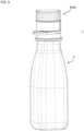
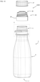
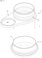
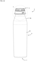
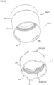
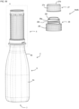
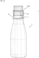
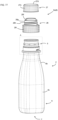
- the dual container 1 includes a container body 2 and a mouth portion attachment 8.
- the container body 2 includes a mouth portion 5, a trunk portion 6, and a bottom portion 7.
- the mouth portion 5 is a cylindrical (preferably circular cylindrical) portion having an open end 5c.
- the mouth portion 5 includes an engaging portion 4m to which a mouth portion attachment 8 such as a cap or a pump can be attached.
- the mouth portion 5 is provided with a flange 5b.
- the flange 5b can be used to support the mouth portion 5, when the mouth portion attachment 8 is attached to the mouth portion 5.
- "axial direction” and “circumferential direction” mean the axial direction and circumferential direction of the mouth portion 5, respectively, unless otherwise specified.
- the direction toward the bottom portion 7 will be referred to as “down”, and the direction toward the mouth portion 5 will be referred to as “up”.
- the direction in which the inner bag 4 comes out from the container body 2 is referred to as "outward”.
- the trunk portion 6 is disposed adjacent to the mouth portion 5 on a side further away from the opening end 5c than the mouth portion 5.
- the trunk portion 6 has a larger outer diameter (in this specification, "outer diameter” means an equivalent circle diameter when the cross section is not circular) than the mouth portion 5.
- the trunk portion 6 is cylindrical, and the bottom portion 7 is provided at the lower end of the trunk portion 6 and closes the lower end of the trunk portion 6.
- the trunk portion 6 includes a shoulder portion 6b whose outer diameter increases as the distance from the mouth portion 5 increases. Further, the trunk portion 6 includes a trunk portion main body 6c closer to the bottom portion 7 than the shoulder portion 6b.
- the trunk portion main body 6c has, for example, a shape in which the outer diameter is substantially constant toward the bottom portion 7, or a shape in which the diameter decreases toward the bottom portion 7.
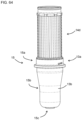
- the container body 2 includes an inner bag 4 and an outer shell 3 disposed to cover the inner bag 4.
- the inner bag main body 4d of the inner bag 4 is housed in the outer shell 3 except for the protrusion 4c.
- portions of the inner bag 4 corresponding to the mouth portion 5, trunk portion 6, and bottom portion 7 of the container body 2 will be referred to as the mouth portion 5, trunk portion 6, and bottom portion 7 of the inner bag 4, respectively.
- the average wall thickness of the outer shell 3 at the center of the trunk portion 6 in the height direction is, for example, 200 to 800 ⁇ m; a wall thickness between 250 and 500 ⁇ m is preferable.
- This wall thickness is, for example, 250, 300, 350, 400, 450, 500, 550, 600, 650, 700, 750, 800 ⁇ m; the wall thickness may also be set to an arbitrary value between any two of these exemplary values.
- the average wall thickness of the inner bag 4 at the center of the trunk portion 6 in the height direction is, for example, 50 to 250 ⁇ m; a wall thickness between 50 and 100 ⁇ m is preferable.
- This wall thickness is, for example, 50, 60, 70, 80, 90, 100, 110, 120, 130, 140, 150, 160, 170, 180, 190, 200, 210, 220, 230, 240, 250 ⁇ m; the wall thickness may also be set to an arbitrary value between any two of these exemplary values.
- the average wall thickness at a predetermined height position means the average value of the measured values at eight measurement points set at equal intervals in the circumferential direction at that height position.
- the mouth portion attachment 8 If the mouth portion attachment 8 is not provided with a check valve, the inner bag 4 does not contract even after the contents of the inner bag 4 are discharged. On the other hand, if the mouth portion attachment 8 is provided with a check valve and an air introduction portion is provided between the outer shell 3 and the inner bag 4 to introduce outside air, the inner bag contracts as the contents are discharged.
- the present invention is applicable to either version.
- the technical significance of the force-reducing configuration is significant in the case where the inner bag 4 does not contract, because in such a case the force required to extract the inner bag 4 tends to be larger than the case where the inner bag 4 contracts.
- the inner diameter of the mouth portion 5 of the outer shell 3 is, for example, 20 to 50 mm; a diameter between 25 and 40 mm is preferable. This diameter is, for example, 20, 25, 30, 35, 40, 45, 50 mm; the diameter may also be set to an arbitrary value between any two of these exemplary values.
- the length of the mouth portion 5 is, for example, 15 to 45 mm; a length between 15 and 35 mm is preferable. This length is, for example, 15, 20, 25, 30, 35, 40, 45 mm; the length may also be set to an arbitrary value between any two of these exemplary values.
- the inner bag 4 includes a protrusion 4c that protrudes from the open end 3a of the outer shell 3.
- the protrusion 4c includes a protruding cylinder 4c1, an engaging portion 4m, and an abutting flange 4c4.
- the engaging portion 4m engages with the mouth portion attachment 8 in the axial direction.
- the engaging portion 4m comprises an annular protrusion.
- the "axial direction” is the direction in which the central axis C of the mouth portion 5 extends, or in other words, the direction in which the inner bag 4 is extracted from the container body 2.
- the “circumferential direction” is a direction in which the mouth portion 5 is rotated about the central axis C, or in other words, a direction in which the inner bag 4 is rotated with respect to the outer shell 3 in the mouth portion 5.
- upward means upward in the axial direction
- “downward” means downward in the axial direction.
- the engaging portion 4m is provided with a tapered surface 4m1 on the upper surface. This makes it easy for the annular protrusion 29c (shown in FIG. 5 ) of the mouth portion attachment 8 to get over the engaging portion 4m, as described later.
- the abutting flange 4c4 is arranged at a position where it contacts the open end 3a.
- the abutting flange 4c4 is an annular portion whose diameter is larger than that of the protruding cylinder 4c1. As the abutting flange 4c4 is in contact with the open end 3a, the inner bag 4 is prevented from falling into the outer shell 3.
- An enlarged diameter structure 4k is provided at the open end 4l of the inner bag 4.
- the enlarged diameter structure 4k increases the rigidity of the opening 5 of the inner bag 4 and suppresses deformation of the opening 5 of the inner bag 4.
- the mouth portion attachment 8 is preferably configured to be attachable to the mouth portion 5 of the inner bag 4 by pushing-in.
- the mouth portion attachment 8 can be engaged with and attached to the mouth portion 5 by pressing the mouth portion attachment 8, while it is placed over the mouth portion 5, in the direction toward the bottom portion 7. Since the push-in type mouth portion attachment 8 can be attached by simply pressing, it has the advantage that the step of attaching the mouth portion attachment 8 can be simplified on the line for filling the contents.
- the mouth portion attachment 8 is configured to be removable from the mouth 5.
- the mouth portion attachment 8 is provided with an engaging portion 8c that engages with the inner bag 4, and by removing the portion 8d having the engaging portion 8c from the mouth portion attachment 8, the mouth portion attachment 8 is configured to be removable from the mouth 5.
- the mouth portion attachment 8 is a cap 8a.
- the mouth portion attachment 8 includes an inner plug 26 and an overcap 27.
- the inner plug 26 is engaged with the opening 5 of the inner bag 4 in the axial direction by pushing-in.
- the overcap 27 is screwed onto the inner plug 26.
- the inner plug 26 may be engaged with the mouth portion 5 of the inner bag 4 in the circumferential direction and the axial direction by pushing-in.
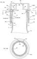
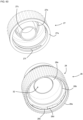
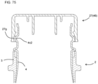
- the overcap 27 includes an outer cylinder 27a, an intermediate cylinder 27b, an inner cylinder 27c, and a top plate 27d.
- a knurl 27e is provided on the outer peripheral surface of the outer cylinder 27a, making it easy to grip and rotate the overcap 27.
- a female threaded portion 27f is provided on the inner peripheral surface of the outer cylinder 27a.
- the top plate 27d is provided on the upper surface of the outer cylinder 27a.
- the intermediate cylinder 27b and the inner cylinder 27c are provided on the lower surface of the top plate 27d.
- the intermediate cylinder 27b is a so-called inner ring that has a smaller diameter than the outer cylinder 27a and is arranged inside the outer cylinder 27a.
- the inner cylinder 27c has a smaller diameter than the intermediate cylinder 27b, and is arranged inside the intermediate cylinder 27b.
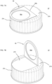
- a hook portion 50 is provided on the top plate 27d of the overcap 27.
- the hook portion 50 is provided with an annular portion 50a; a finger, etc., can be hooked onto the annular portion 50a.
- the hook portion 50 is connected to the top plate 27d via a hinge 50b, and is rotatable about the hinge 50b. Hence, the hook portion 50 can be placed in a lying position as shown in FIG. 7A , or in an upright position as shown in FIG. 7B .
- a recess 27h capable of accommodating the hook 50 is provided on the upper surface of the top plate 27d; when using the dual container 1, the hook portion 50 can be kept out of the way by folding it down and storing it in the recess 27h. In a state where the hook portion 50 is housed in the recess 27h, it is preferable that the top surface of the hook portion 50 and the top surface of the top plate 27d are flush with each other.
- the inner plug 26 includes a main body portion 28, a band portion 29, and an opening portion 32.
- the main body portion 28 and the band portion 29 are connected to each other via an easy-to-tear connecting portion 47.
- the main body portion 28 and the opening portion 32 are connected to each other via an easy-to-tear connecting portion 30.
- the connecting portion 47 is configured to be able to be torn apart by applying force (shearing force, rotational force, etc.) between the main body portion 28 and the band portion 29.
- the connecting portion 47 is preferably thinner than the main body portion 28 and the band portion 29.
- the band portion 29 engages with the mouth portion 5 of the inner bag 4 in the axial direction. Hence, movement of the band portion 29 in the axial direction with respect to the mouth portion 5 of the inner bag 4 is restricted.
- the band portion 29 may or may not engage the mouth portion 5 of the outer shell 3 in the circumferential direction.
- the band portion 29 includes an outer cylinder 29a and an inner cylinder 29b.
- Inner cylinder 29b is arranged inside outer cylinder 29a.
- the outer cylinder 29a and the inner cylinder 29b are connected at the lower end of the band portion 29, and the inner cylinder 29b is connected to the main body portion 28 via the connecting portion 47.
- the inner cylinder 29b is arranged so as to surround the engaging portion 4m of the inner bag 4.
- An annular protrusion 29c extending in the circumferential direction is provided on the inner peripheral surface of the inner cylinder 29b. The annular protrusion 29c engages with the engaging portion 4m in the axial direction, so that the band portion 29 engages with the mouth portion 5 of the inner bag 4 in the axial direction.
- a tapered surface is provided on the lower side of the annular protrusion 29c, reducing the force required for the annular protrusion 29c to climb over the engaging portion 4m. Note that the band portion 29 having the annular protrusion 29c corresponds to the portion 8d having the above-mentioned engaging portion 8c.
- the outer cylinder 29a of the band portion 29 is provided with a tear initiation portion 51.
- the tear initiation portion 51 comprises a thin wall portion, a notch, and a cut.
- the band portion 29 can be removed by tearing the connecting portion 47 after starting tearing at the tear initiation portion 51. Then, by removing the band portion 29, the mouth portion attachment 8 can be removed from the mouth portion 5.
- the main body portion 28 includes an outer cylinder 28a, an inner cylinder 28b, a top plate 28e, a discharge cylinder 28f, and a mounting cylinder 28g.
- the opening portion 32 and the connecting portion 30 are arranged inside the discharge cylinder 28f and the inner cylinder 28b.
- the opening portion 32 is provided with an engaging cylinder 32a provided with an engaging portion (not shown), and the inner cylinder 27c and the engaging cylinder 32a are engaged in the circumferential direction and the axial direction. According to such a configuration, by rotating the overcap 27 with respect to the main body portion 28, it becomes possible to rotate the engaging cylinder 32a with respect to the main body portion and break the connecting portion 30.
- breaking the connecting portion 30 the opening portion 32 is separated from the main body portion 28, and a flow hole is formed inside the discharge cylinder 28f and the inner cylinder 28b. The contents in the inner bag 4 can be discharged through this flow hole.
- the top plate 28e is provided on the upper surface of the outer cylinder 28a.
- An inner cylinder 28b is provided on the lower surface of the top plate 28e.
- the inner cylinder 28b is a so-called inner ring that has a smaller diameter than the outer cylinder 28a and is arranged inside the outer cylinder 28a.
- a discharge cylinder 28f and a mounting cylinder 28g are provided on the upper surface of the top plate 28e.
- the contents in the inner bag 4 are discharged through the discharge cylinder 28f.
- a male threaded portion 28h is provided on the outer peripheral surface of the mounting cylinder 28g
- a female threaded portion 27f is provided on the inner peripheral surface of the outer cylinder 27a of the overcap 27; as the male threaded portion 28h engages with female threaded portion 27f, the overcap 27 is screwed onto the inner plug 26.
- the overcap 27 can be attached to and removed from the inner plug 26 by rotating the overcap 27 relative to the inner plug 26.
- the overcap 27 When the overcap 27 is attached to the inner plug 26, the intermediate cylinder 27b is inserted into the discharge cylinder 28f, and the outer peripheral surface of the intermediate cylinder 27b is brought into close contact with the inner peripheral surface of the discharge cylinder 28f. The upper side of the discharge cylinder 28f is closed by the overcap 27.
- the inner bag 4 is extractable from the container main body 2 by placing the hook portion 50 in an upright state as shown in FIG. 7B and hooking a finger on the annular portion 50a and pulling it. Since the mouth portion attachment 8 is not engaged with the outer shell 3, the inner bag 4 is extractable without performing an operation to release the engagement between the mouth portion attachment 8 and the outer shell 3.
- the inner bag 4 may be extracted after or while being twisted, or may be extracted without being twisted. If the inner bag 4 is not twisted, the force required to extract the inner bag 4 tends to be large, but by hooking a finger on the annular portion 50a, it is easy to apply a strong force to the inner bag 4.
- the band portion 29 can be removed to remove the mouth portion attachment 8 from the inner bag 4. Hence, it is easy to separate the inner bag 4 and the mouth portion attachment 8.
- the mouth portion attachment 8 may be removed from the inner bag 4 before the inner bag 4 is extracted, it is preferably removed from the inner bag 4 after the inner bag 4 is extracted, because in the latter case, the mouth portion attachment 8 can be used to twist or pull the inner bag 4.
- each member can be recycled in an appropriate manner, which renders the dual container 1 excellent recyclability.
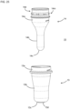
- the container body 2 can be formed by heating a preform 15 and performing biaxial stretch blow molding.
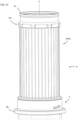
- the preform 15 can be constructed by covering an inner preform 14, which will become the inner bag 4, with an outer preform 13, which will become the outer shell 3.
- the inner preform 14 has a bottomed cylindrical shape and includes a mouth portion 14a, a trunk portion 14b, and a bottom portion 14c.
- a protrusion 14d is provided at the open end of the mouth 14a.
- the protrusion 14d does not deform during molding and becomes the protrusion 4c in its original shape. Hence, the descriptions of the protrusion 4c also apply to the protrusion 14d.
- the protrusion 14d is provided with an engaging portion 14m.
- the engaging portion 14m becomes the engaging portion 4m after molding.
- the bottom portion 14c is provided to close the lower end of the trunk portion 14b.
- a positioning pin (not shown) may be provided on the bottom portion 14c.
- the outer preform 13 has a bottomed cylindrical shape and includes a mouth portion 13a, a trunk portion 13b, and a bottom portion 13c.
- the bottom portion 13c is provided to close the lower end of the trunk portion 13b.
- the bottom portion 13c is provided with an annular protrusion 13d and a positioning hole (not shown).
- the preform 15 can be formed by covering the inner preform 14 with the outer preform 13. If the inner preform 14 is provided with a positioning pin, this positioning pin can be inserted into the positioning hole of the outer preform 13 to position the inner preform 14 and the outer preform 13 relative to each other. In the preform 15, the opening 14a and the opening 13a face each other, and the trunk portion 14b and the trunk portion 13b face each other.
- the mouth portions 13a and 14a become the mouth portion of the preform 15
- the trunk portions 13b and 14b become the trunk portion of the preform 15
- the bottom portions 13c and 14c become the bottom portion of the preform 15.
- the trunk portion and bottom portion of the preform 15 are mainly stretched in biaxial stretch blow molding.
- the inner preform 14 and the outer preform 13 can be formed by direct blow molding, injection molding, or the like of a thermoplastic resin such as polyester (e.g., PET) or polyolefin (e.g., polypropylene, polyethylene).
- a thermoplastic resin such as polyester (e.g., PET) or polyolefin (e.g., polypropylene, polyethylene).
- the inner preform 14 is made of polyolefin (e.g., polypropylene) and the outer preform 13 is made of PET.
- the polyolefin used for the inner preform 14 is preferably polypropylene rather than polyethylene. This is because the temperature at which polypropylene is suitable for biaxial stretch blow molding is closer to that of PET than polyethylene.
- the preform 15 may be constructed by separately manufacturing the inner preform 14 and the outer preform 13 and then covering the inner preform 14 with the outer preform 13, or may be manufactured by multilayer injection molding or two-color molding. By either method, a preform 15 constructed by laminating an inner preform 14 and an outer preform 13 can be obtained.
- a multilayer preform 15 having layers corresponding to the inner preform 14 and the outer preform 13 can be manufactured in a single injection molding step.
- one of the inner preform 14 and the outer preform 13 is molded in the first molding step, and the other of the inner preform 14 and the outer preform 13 is molded in the second molding step.
- the first molding step may be direct blow molding or injection molding.
- the second molding step is preferably injection molding.
- the inner preform 14 is preferably formed by direct blow molding using a molten cylindrical parison. Since it is easier to reduce wall thickness and to use multiple layers in direct blow molding than in injection molding, forming the inner preform 14 in direct blow molding enables to make the inner bag 4 thinner and to form the inner bag 4 with a multi-layer structure.
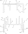
- seal portion 43 is made to protrude from the main body portion 14q of the inner preform 14 to form a protruding seal portion 42, as shown in FIG. 9 .
- the protruding seal portion 42 is formed by welding the inner surfaces of a cylindrical parison together, and protrudes from the main body portion 14q of the inner preform 14.
- the main body portion 14q refers to a portion of the inner preform 14 other than the protruding seal portion 42.
- protruding the seal portion 43 to form the protruding seal portion 42 increases the area of the sealing surface, which increases the sealing strength of the seal portion 43.
- the present invention can also be implemented in the following forms:
- FIGs. 9 to 11 A second embodiment of the present invention will be described using FIGs. 9 to 11 .
- the main difference between this embodiment and the first embodiment is that the inner bag 4 is provided with a hook portion 50 having an annular portion 50a.
- the differences are mainly explained below.
- a hook portion 50 is provided on the protrusion 4c of the inner bag 4.
- the hook portion 50 is provided with an annular portion 50a, and a finger or the like can be hooked onto the annular portion 50a.
- the hook portion 50 is provided at a position facing the open end 3a of the outer shell 3, and the inner bag 4 is positioned in the axial direction with respect to the outer shell 3 by the hook portion 50 coming into contact with the open end 3a.
- the engaging portion 4m of the inner bag 4 is constituted by an annular protrusion.
- the inner bag 4 is extractable from the container body 2 by hooking a finger on the annular portion 50a and pulling it.
- the inner bag 4 may be extracted after or while being twisted, or may be extracted without being twisted. Since the mouth portion attachment 8 is not engaged with the outer shell 3, the inner bag 4 is extractable without performing an operation to release the engagement between the mouth portion attachment 8 and the outer shell 3. If the inner bag 4 is not twisted, the force required to extract the inner bag 4 tends to be large, but by hooking a finger on the annular portion 50a, it is easy to apply a strong force to the inner bag 4.
- the mouth portion attachment 8 can be removed from the inner bag 4 by removing the band portion 29.
- the mouth portion attachment 8 may be removed before or after the inner bag 4 is extracted. According to this embodiment, since the dual container 1 can be separated into the outer shell 3, the inner bag 4, and the mouth portion attachment 8, each member can be recycled in an appropriate manner, which renders the dual container 1 excellent recyclability.
- the regeneration treatment includes, for example, a crushing treatment, a cleaning treatment, a deodorizing treatment, and a pelletizing treatment. Although these treatments are preferably performed in this order, the cleaning treatment may be performed after the deodorizing treatment. Further, one or both of the deodorizing treatment and the cleaning treatment may be omitted if unnecessary.
- the regenerated resin is preferably in the form of pellets. The regenerated resin may be used for manufacturing the dual container 1, or may be used for other purposes. The regenerated resin may be used alone or in combination with an unused virgin resin.
- the main resin of the inner bag 4 and the main resin of the mouth portion attachment 8 are preferably similar resins, and preferably the same resin.
- the main resin of the inner bag 4 is a resin that accounts for 51% by mass or more of all the resins constituting the inner bag 4.
- the main resin of the mouth portion attachment 8 is a resin that accounts for 51% by mass or more of all the resins constituting the mouth portion attachment 8.
- the proportion of the main resin in the inner bag 4 or the mouth portion attachment 8 is, for example, 51 to 100% by mass; a proportion between 80 and 100% is preferable. This proportion is, for example, 51, 55, 60, 65, 70, 75, 80, 85, 90, 95, 100% by mass; the proportion may also be set to an arbitrary value between any two of these exemplary values.
- the proportion of the main resin in the inner bag 4 and the proportion of the main resin in the mouth portion attachment 8 may be the same or different.
- Similar resins are resins in which 80% by mass (preferably 85, 90, or 95% by mass) or more of monomer units are common.
- Examples of similar resins include polyolefin-based resins such as polypropylene-based resins and polyethylene-based resins.
- Examples of polypropylene-based resins include propylene homopolymers, propylene copolymers that are copolymers of propylene and other olefins (such as ethylene), and acid-modified polypropylene.
- polypropylene copolymers include random copolymers and block copolymers of propylene and ethylene.
- polyethylene-based resins examples include ethylene homopolymers, ethylene copolymers that are copolymers of ethylene and other olefins (e.g., ⁇ -olefins such as 1-butene), and acid-modified polyethylene.
- ethylene homopolymer examples include high density polyethylene (HDPE) and low-density polyethylene (LDPE).
- LDPE low-density polyethylene
- ethylene copolymers include linear low-density polyethylene (LLDPE).
- the proportion of other olefin units in the propylene copolymer or ethylene copolymer is, for example, 1 to 20% by mass. This proportion is, for example, 1, 2, 3, 4, 5, 6, 7, 8, 9, 10, 15, 20% by mass; the proportion may also be set to an arbitrary value between any two of these exemplary values.
- the same resin means resins in which the monomers constituting the resins are the same.
- the monomers constituting the resins are the same.
- propylene homopolymers or ethylene homopolymers they are the same resin even if their molecular weights and branched structures are different.
- propylene copolymers for example, a random copolymer and a block copolymer of propylene and ethylene are the same resin.
- a propylene homopolymer and a propylene copolymer do not have the same monomer; hence, although they are similar resins, they are not the same resin.
- the total different resin ratio calculated by [(Ac+Bc)/(A+B)] is preferably 10% by mass or less, and more preferably 5% by mass, wherein A is the mass of the inner bag 4, Ac is the mass of the different resin other than the main resin in the inner bag 4, B is the mass of the mouth portion attachment 8, and Bc is the mass of the different resin other than the main resin in the mouth portion attachment 8.
- the total different resin ratio means the proportion of the total mass of the different resins in the inner bag 4 and the different resins in the mouth portion attachment 8 to the total mass of the inner bag 4 and the mouth portion attachment 8, which is equivalent to the different resin ratio in the regenerated resin.
- the different resin of the inner bag 4 or the mouth portion attachment 8 means a resin other than the main resin of the inner bag 4 or the mouth portion attachment 8.
- the total different resin ratio is, for example, 0, 1, 2, 3, 4, 5, 6, 7, 8, 9, 10% by mass; the ratio may also be set to an arbitrary value between any two of these exemplary values.
- the inner bag different resin ratio calculated by Ac/A is preferably 5% by mass or more, and more preferably 10% by mass or more. Although it becomes more difficult for the regenerated resin to be recognized as a monomaterial as the inner bag different resin ratio increases, the technical significance of applying the invention of this perspective becomes more remarkable as the inner bag different resin ratio increases, because in the invention of this perspective, the total different resin ratio can be reduced by carrying out a regeneration treatment on the inner bag 4 and the mouth portion attachment 8 together.
- the inner bag different resin ratio is, for example, 5 to 49% by mass, specifically, for example, 5, 10, 15, 20, 25, 30, 35, 40, 45, 49% by mass; the ratio may also be set to an arbitrary value between any two of these exemplary values.
- the different resin for the inner bag 4 is preferably a gas barrier resin with excellent gas barrier properties such as EVOH or polyamide. It is preferable that the inner bag 4 includes a gas barrier layer made of a gas barrier resin. This improves the gas barrier properties of the inner bag 4.
- the proportion of different resins in the mouth portion attachment calculated by Bc/B is preferably 20% by mass or less, more preferably 10% by mass or less. Since the mouth portion attachment 8 is not normally provided with a gas barrier layer, the mouth portion attachment 8 can be made of only the main resin. From the viewpoint of making regenerated resin into a monomaterial, it is preferable that the mouth portion attachment 8 is made of only the main resin.
- the proportion of different resins in the mouth portion attachment is, for example, 0 to 20% by mass, and specifically, for example, 0, 1, 2, 3, 4, 5, 10, 15, and 20% by mass; the proportion may also be set to an arbitrary value between any two of these exemplary values.
- the ratio of the sum of the mass A of the inner bag 4 and the mass B of the mouth portion attachment 8 to the mass A of the inner bag 4 is expressed by a dilution ratio calculated as [(A+B)/A].
- the dilution ratio is preferably 2 or more, more preferably 3 or more.
- the dilution ratio is, for example, 2 to 20, specifically, for example, 2, 3, 4, 5, 6, 7, 8, 9, 10, 11, 12, 13, 14, 15, 16, 17, 18. , 19, 20; the ratio may also be set to an arbitrary value between any two of these exemplary values.
- the allowable proportion of different resins in the inner bag becomes higher as the dilution ratio increases.
- the maximum allowable different resin ratio of the inner bag can be calculated as dilution ratio multiplied by the maximum value of the total different resin ratio. For example, if the goal is to make regenerated resin into a monomaterial, and if the maximum value of the total different resin ratio is 5% by mass and the dilution ratio is 3, then the maximum allowable different resin ratio of the inner bag is 15% by mass.
- the different resin ratio of the inner bag by controlling the different resin ratio of the inner bag to 15% by mass or less, it is possible to make the regenerated resin into a monomaterial. If only the inner bag 4 is to be put through a regeneration treatment, the different resin ratio of the inner bag needs to be 5% by mass or less, but it can be seen that by carrying out a regeneration treatment on the mouth portion attachment 8 and the inner bag 4 together, the ratio of different resins that can be included in the inner bag 4 is significantly increased.
- the maximum value of the total different resin ratio may be set to a value necessary to achieve monomaterialization of the regenerated resin, and may be set to 10% by mass, for example.
- the first embodiment shown below mainly relates to the 2B perspective
- the second embodiment mainly relates to the 2A perspective
- the third embodiment mainly relates to the 2C perspective.
- the descriptions of the first to third embodiments are mutually applicable unless doing so contradicts the scope of the descriptions.
- the descriptions provided in relation to the 2A to 2C perspectives are mutually applicable unless doing so contradict the scope of the descriptions.
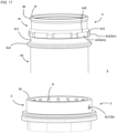
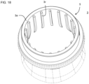
- the dual container 1 of this embodiment has a structure shown in FIGs. 14 to 20 .
- the descriptions of the first embodiment of the first perspective also apply to this embodiment unless doing so contradicts the scope of the descriptions. The differences are mainly explained below.
- the mouth portion attachment 8 is provided with a check valve (not shown), which allows the contents of the inner bag 4 to be discharged, but restricts the inflow of outside air into the inner bag 4.
- the outer shell 3 is provided with an air introduction portion 3p, and the outside air enters the intermediate space 55 between the inner bag 4 and the outer shell 3 through the air introduction portion 3p.
- the inner bag 4 is configured to contract away from the outer shell 3 as the contents of the inner bag 4 decrease.
- the air introducing portion 3p is constituted by through holes 3p1 provided in the mouth portion 5 of the outer shell 3.
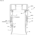
- the outer shell 3 is provided with a sealing flange 3q at a position closer to the open end 3a than the flange 5b; a sealed space 53 surrounded by the container body 2 and the mouth portion attachment 8 is formed by the inner surface of the cylindrical portion 8e of the mouth portion attachment 8 coming into close contact with the outer periphery of the sealing flange 3q.
- the closed space 53 communicates with the intermediate space 55 through the outside air introducing portion 3p.
- the air introduction portion 3p is arranged within the closed space 53. As shown in FIG.
- the cylindrical portion 8e of the mouth portion attachment 8 is provided with a through hole 8f.
- a valve member 54 is attached to the through hole 8f.
- the through hole 8f is provided to communicate the closed space 53 with the outside of the dual container 1.
- the valve member 54 is configured to be able to control the flow of air through the through hole 8f.
- the valve member 54 includes a cylindrical body 54a and a movable body 54b, and is configured to be openable and closable as the movable body 54b moves relative to the cylindrical body 54a.
- the movable body 54b is preferably spherical.
- the through holes 3p1 are provided in the mouth portion 5 of the outer shell 3, and if the outer shell 3 and the inner bag 4 are in close contact with each other at the mouth portion 5, it is not easy for outside air to enter the trunk portion 6 of the container body 2, and the contractibility of the inner bag 4 tends to deteriorate.
- protruding strips 3r extending toward the bottom portion 7 side of the outer shell 3 are provided. By providing the protruding strips 3r, a gap is formed between the outer shell 3 and the inner bag 4, making it easy for outside air to enter the trunk portion 6 of the container body 2.
- the protruding strips 3r extend toward the bottom portion 7 side of the outer shell 3, starting from a height position where the through holes 3p1 are provided or a position higher than that. It is preferable that the protruding strips 3r are positioned adjacent to the through holes 3p1. Moreover, it is preferable that a plurality of protruding strips 3r are positioned so as to sandwich the through holes 3p1.
- the number of the protruding strips 3r is, for example, 1 to 40, preferably 2 to 30 (18 in this embodiment). Specifically, this number is, for example, 1, 2, 3, 4, 5, 6, 7, 8, 9, 10, 15, 18, 20, 25, 30, 35, 40; this number may also be set to an arbitrary value between any two of these exemplary values.
- the protruding strips 3r are provided at positions closer to the bottom portion 7 than the flange 5b.
- Each of the width and height of the protruding strips 3r is, for example, 0.2 to 3 mm, preferably 0.5 to 2 mm.
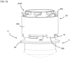
- the inner bag 4 includes a protrusion 4c that protrudes from the open end 3a of the outer shell 3.
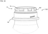
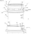
- the protrusion 4c includes a protruding cylinder 4c1, engaging protrusions 4c2, annular protrusions 4c5, and an abutting flange 4c4.
- the annular protrusions 4c5 engage with the mouth portion attachment 8 in the axial direction.
- the engaging protrusions 4c2 engage with the mouth portion attachment 8 in the circumferential direction.
- the "axial direction” is the direction in which the central axis C of the mouth portion 5 extends, or in other words, the direction in which the inner bag 4 is extracted from the container body 2.
- the "circumferential direction” is a direction in which the mouth portion 5 is rotated about the central axis C, or in other words, a direction in which the inner bag 4 is rotated with respect to the outer shell 3, in the mouth portion 5.
- upward direction means upward in the axial direction
- “downward direction” means downward in the axial direction.
- the engaging protrusions 4c2 are provided at a plurality of locations (eight locations in this embodiment) spaced apart in the circumferential direction.
- the engaging protrusions 4c2 are arranged on the annular protrusions 4c5, and is arranged so as to protrude radially outward from the annular protrusion 4c5.
- the annular protrusions 4c5 and the engaging protrusions 4c2 are provided with tapered surfaces 4c8 and 4c3 on their upper surfaces. This makes it easy for the annular protrusions 28c (shown in FIGs. 19 and 20 ) of the mouth portion attachment 8 to climb over the annular protrusions 4c5 and the engaging protrusions 4c2, as described later.
- the abutting flange 4c4 is an annular portion disposed at a position abutting the open end 3a and having a diameter larger than that of the protruding cylinder 4c1.
- An enlarged diameter structure 4k is provided at the open end 4l of the inner bag 4.
- the enlarged diameter structure 4k increases the rigidity of the opening 5 of the inner bag 4 and suppresses deformation of the opening 5 of the inner bag 4.
- the inner bag 4 is extracted using the engaging portion 4m (more specifically, the annular protrusions 4c5 and the engaging protrusions 4c2) provided on the inner bag 4, there are cases where a high load is applied to the inner bag 4. In such cases, it may become difficult to extract the inner bag 4 if the opening end 4l of the inner bag 4 is easily deformed. In this embodiment, however, the inner bag 4 is smoothly extractable since the deformation of the open end 4l of the inner bag 4 is suppressed.
- the mouth portion attachment 8 is a cap 8a, and includes an inner plug 26, an overcap 27, and a valve member 54.
- the inner plug 26 is engaged, by pushing-in, with the opening 5 of the inner bag 4 in the circumferential direction and the axial direction.
- the overcap 27 is removably attached to the inner plug 26, and by removing the overcap 27, the contents can be discharged through the mouth portion attachment 8.
- the inner plug 26 includes a main body portion 28.
- the main body portion 28 includes an outer cylinder 28a, an inner cylinder 28b, an annular protrusion 28c, an engaging protrusion 28d, a top plate 28e, and a flow hole 28j.
- the flow hole 28j is provided in the top plate 28e, and the contents inside the inner bag 4 can be discharged through the flow hole 28j.
- the top plate 28e is provided on the upper surface of the outer cylinder 28a.
- An inner cylinder 28b is provided on the lower surface of the top plate 28e.
- the inner cylinder 28b is a so-called inner ring that has a smaller diameter than the outer cylinder 28a and is arranged inside the outer cylinder 28a.
- the annular protrusions 28c are annular protrusions provided on the inner peripheral surface of the outer cylinder 28a in such a way to extend in the circumferential direction.
- the engaging protrusions 28d are provided at a plurality of locations (eight locations in this embodiment) spaced apart in the circumferential direction.
- the engaging protrusions 28d are disposed on the annular protrusion 28c, and are arranged so as to protrude radially inward from the annular protrusions 28c.
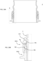
- the engaging protrusions 28d are arranged between the adjacent engaging protrusions 4c2, so that the main body portion 28 engages with the mouth portion 5 of the inner bag 4 in the circumferential direction.
- the mouth portion attachment 8 is engaged with the mouth portion 5 of the inner bag 4 in the circumferential direction and the axial direction, and the mouth portion 5 of the inner bag 4 is configured to rotate with respect to the outer shell 3 as the mouth portion attachment 8 rotates. Therefore, by rotating the mouth portion attachment 8, the inner bag 4 can be twisted.
- the inner bag 4 is extractable by grasping and pulling the mouth portion attachment 8. In this embodiment, although the inner bag 4 is deflated after the contents are used up, it becomes significantly easy to extract the inner bag 4 by twisting the inner bag 4.
- the container body 2 can be formed by heating a preform 15 and performing biaxial stretch blow molding.
- preform 15 the descriptions of the first embodiment of the first perspective also apply to this embodiment unless doing so contradicts the scope of the descriptions. The differences are mainly explained below.
- Through holes 13e are provided in the mouth portion 13a of the outer preform 13. Since the mouth portion 13a is hardly deformed during biaxial stretch blow molding, the through holes 13e become the through holes 3p1 of the outer shell 3.
- the inner surface of the mouth portion 13a of the outer preform 13 is provided with protruding strips 13f extending toward the bottom side of the outer preform 13. It is preferable that the protruding strips 13f are provided in such a way to extend toward the bottom side of the outer preform 13 starting from a height position where the through holes 13e are provided or a position higher than that.
- the protruding strips 13f become the protruding strips 3r of the outer shell 3 after biaxial stretch blow molding.
- the protruding strips 13f are preferably provided across the mouth portion 13a and the trunk portion 13b.
- the portions of the protruding strips 13f provided at the mouth portion 13a are hardly deformed during biaxial stretch blow molding, and the portion provided on the trunk portion 13b is stretched together with the trunk portion 13b.
- the position of the lower ends 13g of the protruding strips 13f is preferably 0.8H or less from the lower end 13h of the outer preform 13.
- the position of the lower ends 13g of the protruding strips 13f is, for example, 0.1H to 0.8H from the lower end 13h of the outer preform 13, preferably 0.4H to 0.8H, and specifically, for example, 0.1H, 0.2H, 0.3H, 0.4H, 0.5H, 0.6H, 0.7H, and 0.8H; this number may also be set to an arbitrary value between any two of these exemplary values or an arbitrary value below any of these exemplary values.
- the protruding strips 13f are preferably positioned adjacent to the through holes 13e. Moreover, it is preferable that a plurality of protruding strips 13f are positioned so as to sandwich the through holes 13e.
- the number of protruding strips 13f is, for example, 1 to 40, preferably 2 to 30 (18 in this embodiment). Specifically, this number is, for example, 1, 2, 3, 4, 5, 6, 7, 8, 9, 10, 15, 18, 20, 25, 30, 35, 40; this number may also be set to an arbitrary value between any two of these exemplary values.
- Each of the width and height of the protruding strips 13f is, for example, 0.2 to 3 mm, preferably 0.5 to 2 mm.
- the outer preform 13 is manufactured by injection molding and the inner preform 14 is manufactured by direct blow molding. Since objects manufactured by direct blow molding has lower shape accuracy than those manufactured by injection molding, trying to provide a protruding strip on the outer surface of the inner preform 14, which is manufactured by direct blow molding, could decrease the shape accuracy of the protruding strip and make it difficult to introduce outside air into the trunk portion 6 after biaxial stretch blow molding. On the other hand, in injection molding, the shape accuracy of manufactured objects is high, so trying to provide the protruding strips 13f on the inner surface of the outer preform 13, which is manufactured by injection molding, is unlikely to decrease the shape accuracy of the protruding strips 13f and prevents the above problem.
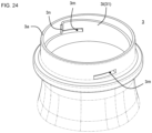
- FIGs. 23 to 26 A second embodiment of the present invention is described using FIGs. 23 to 26 .
- the dual container 1 of this embodiment is similar to the first embodiment, and the differences are mainly described below.
- the dual container 1 of this embodiment may be implemented in such a manner that the inner bag 4 contracts as the contents of the inner bag 4 decrease, or may be implemented in a manner in which the inner bag 4 does not contract.
- the dual container 1 of this embodiment may be implemented in such a manner that the inner bag 4 contracts as the contents of the inner bag 4 decrease, or may be implemented in a manner in which the inner bag 4 does not contract.
- the valve member 54 there is no need to provide the mouth portion attachment 8 with a check valve that allows the contents of the inner bag 4 to be discharged while restricting the inflow of outside air into the inner bag 4.
- the dual container 1 of this embodiment assumes that the inner bag 4 is extracted from the container body 2 after the contents of the inner bag 4 are used up, and in order to facilitate the extracting of the inner bag 4, the configuration shown below is provided.
- cam protrusions 4g and engaging protrusions 4h are provided on the outer peripheral surface of the inner bag body 4d.
- the engaging protrusions 4h are provided on the cam protrusions 4g.
- the lower surfaces of the cam protrusions 4g and the engaging protrusions 4h are respectively inclined so as to approach the open end 5c as they proceed counterclockwise, when viewed from the open end 5c side of the mouth portion 5.
- the inner peripheral surface of the outer shell 3 is provided with cam rails 3l, engaging recesses 3m, and engaging protrusions 3n.
- the engaging recesses 3m are provided such that the lower surfaces of the engaging recesses 3m are continuous with the upper surfaces of the cam rails 3l.
- the upper surfaces of the cam rails 31 and the lower surfaces of the engaging recesses 3m are inclined so as to approach the opening end 3a as they proceed counterclockwise, when viewed from the opening end 3a side.
- the engaging protrusions 3n are positioned adjacent to the engaging recesses 3m.
- the engaging protrusions 4h are disposed within the engaging recesses 3m, and the lower surfaces of the cam protrusions 4g are in contact with the upper surfaces of the cam rails 3l.
- a cam mechanism 31 is constituted by the cam protrusions 4g and the cam rails 3l.
- the engaging recesses 3m are through holes, but may be non-through holes.
- the engagement structure between the inner bag 4 and the mouth portion attachment 8 is similar to that in the first embodiment, and by rotating the mouth portion attachment 8, the inner bag 4 can be twisted.
- the same method as in the first embodiment is applicable to the dual container 1 of this embodiment, except that the shape of the preform 15 is different.
- the preform 15 of this embodiment has the shape shown in FIGs. 25 to 26 .
- Di 0.2 /Do 0.2 is preferably 0.70 or less wherein H is the total height of the outer preform 13, Di 02 ; is the outer diameter of the inner preform 14 at a position 0.2H from the lower end 13h of the outer preform 13, and Do 0.2 is the outer diameter of the outer preform 13. If Di 0.2 /Do 0.2 is 0.70 or less, the inner preform 14 is stretched to a greater extent than the outer preform 13 near the bottom of the preform 15 during biaxial stretch blow molding, reducing the thickness. Hence, the inner bag 4 can be made particularly thin.
- Di 0.2 /Do 0.2 is, for example, 0.10 to 0.70, specifically, for example, 0.10, 0.15, 0.20, 0.25, 0.30, 0.35, 0.40, 0.45, 0.50, 0.55, 0.60, 0.65, 0.70; the value of Di 0.2 /Do 0.2 may also be set to an arbitrary value between any two of these exemplary values.
- the thickness of the inner preform 14 at the 0.2H position is, for example, 0.5 to 2.0 mm, specifically, for example, 0.5, 0.6, 0.7, 0.8, 0. 9, 1.0, 1.1, 1.2, 1.3, 1.4, 1.5, 1.6, 1.7, 1.8, 1.9, 2.0mm; this thickness may also be set to an arbitrary value between any two of these exemplary values.
- the thickness of the outer preform at the 0.2H position is, for example, 1.5 to 4.0 mm, specifically, for example, 1.5, 2.0, 2.5, 3.0, 3..5, 4.0mm; this thickness may also be set to an arbitrary value between any two of these exemplary values.
- the value of [thickness of outer preform 13/thickness of inner preform 14] at the position of 0.2H is, for example, 1.0 to 3.0, specifically, for example, 1.0, 1.1, 1.2, 1.3, 1.4, 1.5, 1.6, 1.7, 1.8, 1.9, 2.0, 2.1, 2.2, 2. 3, 2.4, 2.5, 2.6, 2.7, 2.8, 2.9, 3.0, and may also be set to an arbitrary value between any two of these exemplary values.
- Di 0.2 is, for example, 6 to 20 mm, preferably 8 to 16 mm. Specifically, this value is, for example, 6, 7, 8, 9, 10, 11, 12, 13, 14, 15, 16, 17, 18, 19, 20 mm, and may also be set to an arbitrary value between any two of these exemplary values.
- Do 0.2 is, for example, 12 to 40 mm, preferably 18 to 32 mm. Specifically, this value is, for example, 12, 13, 14, 15, 16, 17, 18, 19, 20, 21, 22, 23, 24, 25, 26, 27, 28, 29, 30, 31, 32, 33, 34, 35, 36, 37, 38, 39, 40mm, and may also be set to an arbitrary value between any two of these exemplary values.
- Di 0.2 /Di is preferably 0.60 or less, wherein Di is the outer diameter of the inner preform 14 at the open end 13i of the outer preform 13. In this case, since the diameter of the inner preform 14 is greatly reduced near the bottom of the preform 15, the thickness of the inner bag 4 is noticeably thinned near the bottom portion 7 of the inner bag 4.
- the value of Di 0.2 /Di is, for example, 0.10 to 0.60, specifically, for example, 0.10, 0.15, 0.20, 0.25, 0.30, 0.35, 0.40, 0.45, 0.50, 0.55, 0.60, and may also be set to an arbitrary value between any two of these exemplary values.
- the inner preform 14 includes an inwardly curved portion 14r that curves so as to be inwardly convex. In this case, the diameter of the inner preform 14 is significantly reduced at the inwardly curved portion 14r.
- the inwardly curved portion 14r is preferably provided at a portion that becomes the shoulder portion 6b of the container body 2 after biaxial stretch blow molding. Since the shoulder portion 6b tends to have a large resistance force when the inner bag 4 is extracted from the container body 2, it may be particularly desirable to make the shoulder portion 6b thinner. Providing the inwardly curved portion 14r tends to increase the blow ratio during biaxial stretch blow molding, enabling the shoulder portion 6b to become thinner.
- H c /H is preferably 0.10 or more, wherein H c is the height range of the inwardly curved portion 14r (that is, the distance in the vertical direction between the upper and lower ends of the inwardly curved portion 14r).
- H c is the height range of the inwardly curved portion 14r (that is, the distance in the vertical direction between the upper and lower ends of the inwardly curved portion 14r).
- the value of H c /H is, for example, 0.10 to 0.60, specifically, for example, 0.10, 0.15, 0.20, 0.25, 0.30, 0.35, 0.40, 0.45, 0.50, 0.55, 0.60, and may also be set to an arbitrary value between any two of these exemplary values.
- the gap 15d between the inner preform 14 and the outer preform 13 is preferably maximized at the inwardly curved portion 14r.
- the inner preform 14 usually expands before the outer preform 13; hence, if there is a gap between the inner preform 14 and the outer preform 13, the inner preform 14 first expands to eliminate this gap, and then the inner preform 14 and the outer preform 13 expand together, to form the container body 2.
- the inner preform 14 is stretched more and thinner in a region where the gap 15d is larger.
- the portion e.g., the shoulder portion 6b
- S max /D imax is, for example, 0.20 to 0.80, specifically, for example, 0.20, 0.25, 0.30, 0.35, 0.40, 0.45, 0.50, 0.55, 0.60, 0.65, 0.70, 0.75, 0.80, and may also be set to an arbitrary value between any two of these exemplary values, wherein S max is the size of the gap 15d at the height position where the gap 15d is maximized, and D imax is the outer diameter of the inner preform 14 at that height position.
- the outer preform 13 is curved so that a portion or all of the portion 13j facing the inwardly curved portion 14r is convex toward the outside.
- Do 0.2 /Do The value of Do 0.2 /Do is 0.95 or less, wherein Do is the outer diameter of the outer preform 13 at the open end 13i of the outer preform 13. This prevents the gap 15d near the bottom from becoming too large, making it easy for the inner preform 14 to selectively expand at the inwardly curved portion 14r.
- the value of Do 0.2 /Do is, for example, 0.50 to 0.95, specifically, for example, 0.50, 0.55, 0.60, 0.65, 0.70, 0.75, 0 .80, 0.85, 0.90, 0.95, and may also be set to an arbitrary value between any two of these exemplary values.
- the inner preform 14 is preferably formed by injection molding.
- injection molding has the advantage of easily improving shape accuracy, it is more difficult to reduce wall thickness than direct blow molding.
- This embodiment is also based on the idea that the thickness of the inner bag 4 is reduced by reducing the diameter of the inner preform 14 without making the inner preform 14 thinner, and the technical significance is particularly significant when the inner preform 14 is formed by injection molding.
- FIGs. 27 to 31 A third embodiment of the present invention is described using FIGs. 27 to 31 .
- the dual container 1 of this embodiment is similar to the second embodiment, and the differences are mainly described below.
- the dual container 1 of this embodiment assumes that the inner bag 4 is extracted from the container body 2 after the contents of the inner bag 4 are used up, and in order to make it easy to extract the inner bag 4, the configuration shown below is provided.
- the outer shell 3 includes an outer shell main body 33 and an engaging member 34 that can be connected to the outer shell main body 33.
- the connection mechanism between the outer shell main body 33 and the engaging member 34 is not limited as long as the outer shell main body 33 is separable from the engaging member 34.
- the outer shell main body 33 and the engaging member 34 are screwed together at the male threaded portion 33b of the outer shell main body 33 and the female threaded portion 34b of the engaging member 34, and the two are rotated relative to each other in the unscrewing direction. This allows the outer shell main body 33 to be separated from the engaging member 34.
- the protrusion 34a of the engaging member 34 protrudes further toward the inside of the container body 2 than the outer shell main body 33.
- the inner bag main body 4d of the inner bag 4 is provided with an engaging protrusion 4q, and when the engaging protrusion 4q engages with the protrusion 34a, the inner bag 4 engages with the engaging member 34 in the axial direction.
- an engaging protrusion 33d that can engage with the engaging protrusion 4q is provided on the inner surface of the mouth portion 5 of the outer shell main body 33, and relative rotation of the inner bag 4 with respect to the outer shell 3 is restricted by the engagement of the engaging protrusion 4q and the engaging protrusion 33d in the circumferential direction.
- a plurality of engaging protrusions 4q and a plurality of engaging protrusions 33d are provided, so that the relative rotational play between the outer shell 3 and the inner bag 4 is reduced.
- the engaging protrusion 33d is unnecessary.
- the engaging protrusion 4q may be formed in an annular shape.
- the outer shell main body 33 can be separated from the container body 2 by separating the outer shell main body 33 from the engaging member 34. If the outer shell main body 33 and the engaging member 34 are screwed together, the outer shell main body 33 can be separated from the engaging member 34 by relatively rotating the outer shell main body 33 and the engaging member 34 in the unscrewing direction.
- the engaging member 34 is in contact with the abutting flange 4c4 of the inner bag 4, and when the outer shell main body 33 is separated from the engaging member 34, a force is generated in the direction in which the engaging member 34 pushes up the abutting flange 4c4, making it easy to extract the inner bag 4.
- the resistance force when separating the inner bag 4 and the outer shell main body 33 is unlikely to become large.
- the same method as in the first embodiment is applicable to the dual container 1 of this embodiment, except that the shape of the preform 15 is different.
- the outer preform 13 includes an outer preform main body 16 and an engaging member 17.
- the outer preform main body 16 and the engaging member 17 become an outer shell main body 33 and an engaging member 34, respectively, after biaxial stretch blow molding.
- the outer preform main body 16 includes a male threaded portion 16b corresponding to the male threaded portion 33b, and is capable of being screwed into engagement with the engaging member 17.
- the inner bag 4 may be engaged with the engaging member 34 in the axial direction.
- the outer shell main body 33 and the engaging member 34 may be screwed together at the female threaded portion 33c provided on the outer shell main body 33 and at the male threaded portion 34d provided on the engaging member 34.
- the third perspective of the present invention includes the 3A and 3B perspectives.
- the dual container 1 of the first embodiment has the structure shown in FIGs. 32 to 41 .
- the descriptions of the first embodiment of the first perspective also apply to this embodiment unless doing so contradicts the scope of the descriptions.
- the mouth portion attachment 8 is a cap 8a.
- the inner bag 4 includes a protrusion 4c that protrudes from the open end 3a of the outer shell 3.
- the protrusion 4c includes a protruding cylinder 4c1, an engaging protrusion 4c2, and an abutting flange 4c4.
- the engaging protrusions 4c2 protrude radially outward from the outer peripheral surface of the protruding cylinder 4c1.
- the engaging protrusions 4c2 are provided at a plurality of locations (eight locations in this embodiment) spaced apart in the circumferential direction.
- Each engaging protrusion 4c2 is provided with a tapered surface 4c3 on the upper surface. This allows the annular protrusion 26c (shown in FIG. 38 ) of the inner plug 26 to easily climb over the engaging protrusions 4c2, as described later.
- the abutting flange 4c4 is an annular portion disposed at a position abutting the open end 3a and having a diameter larger than that of the protruding cylinder 4c1.
- cam protrusions 4g are provided on the outer peripheral surface of the inner bag 4.
- the lower surfaces of the cam protrusions 4g are inclined so as to approach the opening end 5c as the lower surface proceeds counterclockwise (that is, toward upper right in FIG. 35 ), when viewed from the open end 5c side of the mouth portion 5 (hereinafter, unless otherwise specified, the rotation direction means the direction viewed from the open end 5c side of the mouth portion 5).
- the inner peripheral surface of the outer shell 3 is provided with a cam rail 31 and an engaging recess 3m.
- the engaging recesses 3m are arranged in such a way that the lower surfaces of the engaging recesses 3m are continuous with the upper surfaces of the cam rails 3l.
- the upper surfaces of the cam rails 31 and the lower surfaces of the engaging recesses 3m are inclined so as to approach the opening end 3a as they proceed counterclockwise, when viewed from the opening end 3a side.
- a cam mechanism 31 is constituted by the cam protrusions 4g and the cam rails 3l.
- the cam mechanism 31 is configured to displace the inner bag 4 so as to let the inner bag 4 come out of the container body 2, when the inner bag 4 is rotated relative to the outer shell 3.
- the cam protrusions 4g are disposed within an engaging recess 3m, so that the inner bag 4 does not come off from the container body 2.
- the engagement between the cam protrusions 4g and the engaging recesses 3m is released, and the cam protrusions 4g move along the cam rails 3l.
- the inner bag 4 moves along the axial direction of the mouth portion 5 and partially comes out of the container body 2.
- the cap 8a includes an inner plug 26 and a cap main body 87.
- the inner plug 26 includes an outer cylinder 26a, an inner ring 26b, an annular protrusion 26c, an engaging protrusion 26d, a first top plate 26e, a nozzle 26f, and an upper cylinder 26g, a second top plate 26h, an engaging protrusion 26i, and a male threaded portion 26j.
- the first top plate 26e is provided on the upper surface of the outer cylinder 26a.
- An inner ring 26b is provided on the lower surface of the first top plate 26e.
- the inner ring 26b has a smaller diameter than the outer cylinder 26a, and is arranged inside the outer cylinder 26a.
- the outer peripheral surface of the inner ring 26b is in close contact with the inner peripheral surface of the inner bag 4.
- An upper cylinder 26g is provided on the upper surface of the first top plate 26e.
- a male threaded portion 26j is provided on the outer peripheral surface of the upper cylinder 26g.
- the second top plate 26h is provided on the upper surface of the upper cylinder 26g, and the second top plate 26h is provided with a nozzle 26f.
- the nozzle 26f is provided with an opening 26f1.
- the annular protrusion 26c is an annular protrusion provided on the inner peripheral surface of the outer cylinder 26a so as to extend in the circumferential direction.
- the engaging protrusions 26d are provided on the inner peripheral surface of the outer cylinder 26a at a plurality of locations (eight locations in this embodiment) spaced apart in the circumferential direction.
- the engaging protrusion 26d is located further away from the lower end 26k of the inner plug 26 than the annular protrusion 26c.
- the engaging protrusion 26d is arranged between the adjacent engaging protrusions 4c2, so that the inner plug 26 engages with the mouth portion 5 of the inner bag 4 in the circumferential direction.
- the engaging protrusions 26i are provided on the outer peripheral surface of the outer cylinder 26a at a plurality of locations (eight locations in this embodiment) spaced apart in the circumferential direction.
- the engaging protrusion 26i is provided with a tapered surface 26i1.
- the cap main body 87 includes a cap trunk portion 88 and a cap lid portion 89.
- the cap main body 87 can be switched between an engaged state shown in FIG. 32 and a separated state shown in FIG. 37 .
- the engaged state the cap lid portion 89 is engaged with and integrated with the cap trunk portion 88.
- the separated state the cap lid portion 89 is separated from the cap trunk portion 88.
- the cap lid 89 may be completely separated from the cap trunk portion 88 or may be connected by a hinge or the like.
- the cap trunk portion 88 includes an outer cylinder 88a, an inner cylinder 88b, an annular protrusion 88c, an engaging protrusion 88d, a top plate 88e, an opening 88f, an engaging protrusion 88g, and a female screw portion 88h.
- the top plate 88e is provided on the upper surface of the outer cylinder 88a.
- An inner cylinder 88b is provided on the lower surface of the top plate 88e.
- the inner cylinder 88b has a smaller diameter than the outer cylinder 88a, and is arranged inside the outer cylinder 88a.
- a female threaded portion 88h is provided on the inner peripheral surface of the inner cylinder 88b. The female threaded portion 88h can be screwed into the male threaded portion 26j.
- An opening 88f and an engaging protrusion 88g are provided on the upper surface of the top plate 88e.
- the nozzle 26f is inserted into the opening 88f.
- the engaging protrusion 88g engages with the cap lid portion 89 to bring the cap main body 87 into an engaged state.
- the annular protrusion 88c is an annular protrusion provided on the inner peripheral surface of the outer cylinder 88a so as to extend in the circumferential direction.
- the engaging protrusions 88d are provided at a plurality of locations (eight locations in this embodiment) spaced apart in the circumferential direction.
- the engaging protrusion 88d is located further away from the lower end 88i of the cap trunk portion 88 than the annular protrusion 88c.
- the engaging protrusion 88d is provided with a tapered surface 88d1.
- the cap lid portion 89 includes an outer cylinder 89a, an inner ring 89b, a top plate 89c, and a knob 89d.
- the top plate 89c is provided on the upper surface of the outer cylinder 89a.
- An inner ring 89b is provided on the lower surface of the top plate 89c.
- the inner ring 89b has a smaller diameter than the outer cylinder 89a, and is arranged inside the outer cylinder 89a.
- the inner ring 89b is configured such that when the cap main body 87 is attached to the inner plug 26, the outer peripheral surface of the inner ring 89b comes into contact with the inner peripheral surface of the nozzle 26f to close the opening 26f1.
- the knob 89d is provided on the outer peripheral surface of the outer cylinder 89a, and can be used to separate the cap lid portion 89 from the cap trunk portion 88 by hooking a finger on the knob 89d.
- cap 8a it is preferable to assemble the cap 8a before attaching the cap 8a to the mouth portion 5, because doing so can simplify the step of attaching the cap 8a on the line for filling the contents.
- the assembly method is explained in detail below.
- the inner plug 26 is inserted into the cap trunk portion 88 from below the cap trunk portion 88, and while the cap trunk portion 88 is being grasped, the inner plug 26 is rotated clockwise, viewed from below the cap trunk portion 88, to screw the male threaded portion 26j into the female threaded portion 88h.
- the engaging protrusion 26i and the engaging protrusion 88d contact in the circumferential direction, but since the tapered surface 26i1 and the tapered surface 88d1 are provided on the abutting side, the inner plug 26 is able to rotate relative to the cap trunk portion 88 as the engaging portion 26i climbs over the engaging portion 88d.
- the inner plug 26 When the inner plug 26 is further rotated, the inner plug 26 cannot be further rotated once the first top plate 26e comes into contact with the inner cylinder 88b or once the second top plate 26h comes into contact with the top plate 88e, as shown in FIG. 40 .
- the nozzle 26f protrudes above the cap trunk portion 88 through the opening 88f.
- the cap lid portion 89 is attached to the cap trunk portion 88 before or after the cap trunk portion 88 is attached to the inner plug 26.
- the opening 26f1 is closed by the cap main body 87, resulting in a closed state.
- the cap 8a in which the cap main body 87 is attached to the inner plug 26 is obtained.
- the cap 8a is of a push-in type; if the cap 8a is placed over the mouth 5 and an axial force is applied to the cap 8a to press the cap 8a against the mouth 5, the annular protrusion 26c climbs over the engaging protrusions 4c2 and engages in the axial direction, resulting in the cap 8a being attached to mouth portion 5,
- the cap 8a Before starting to extract the inner bag 4, the cap 8a is in a closed state in which the opening 26f1 is closed by the cap main body 87. In this state, the inner bag 4 does not deflate when the inner bag 4 is extracted, and it is not easy to extract the inner bag 4, since the air inside the inner bag 4 cannot be released.
- the cap 8a can be switched from a closed state in which the opening 26f1 is closed to a released state in which the opening 26f1 is unblocked, as shown in FIG. 41 , while the cap main body 87 is attached to the inner plug 26, by moving the cap main body 87 relative to the inner plug 26 in the axial direction. Hence, the inner bag 4 is easily extractable by extracting the inner bag 4 after the cap 8a is released.
- Switching from the closed state to the released state can be done by rotating the cap main body 87 with respect to the inner plug 26.
- the engaging protrusion 88d is located below the engaging protrusion 26i. In this state, the engaging protrusion 88d and the engaging protrusion 26i are not engaged with each other.
- the cap main body 87 rotates. At this time, the cap main body 87 is moved upward in the axial direction by screw feeding, as the male threaded portion 26j and the female threaded portion 88h are unscrewed.
- the engaging protrusion 88d approaches the engaging protrusion 26i, and at a certain point, as shown in FIG. 41 , the engaging protrusion 88d and the engaging protrusion 26i engage in the circumferential direction.
- the threaded engagement between the male threaded portion 26j and the female threaded portion 88h is not completely released and is in a partially threaded state.
- the inner ring 89b moves in the direction of coming out of the nozzle 26f, and at the time when the engaging protrusion 88d and the engaging protrusion 26i engage in the circumferential direction, the cap 8a is in a released state where the closing of the opening 26f1 is released.
- the inner plug 26 rotates together with the cap main body 87. Hence, the threaded engagement between the male threaded portion 26j and the female threaded portion 88h is not further released.
- the inner plug 26 is engaged with the opening 5 of the inner bag 4 in the circumferential direction (more specifically, since the engaging protrusion 26d is engaged with the engaging protrusions 4c2 in the circumferential direction), the opening 5 of the inner bag 4 rotates as the inner plug 26 rotates.
- the inner bag 4 Since the trunk portion 6 of the inner bag 4 is less likely to be rotated than the mouth 5, the inner bag 4 is twisted and reduced in diameter as the mouth 5 of the inner bag 4 rotates. At this point, as the cap 8a is already in the released state, the air inside the inner bag 4 is smoothly released when the inner bag 4 contracts.
- the inner bag 4 is displaced to come out of the container body 2 by the action of the cam mechanism 31.
- This displacement causes at least a portion of the shoulder portion 6b of the inner bag 4 to move to the mouth 5 of the outer shell 3. Since the shoulder portion 6b of the inner bag 4 has an enlarged diameter and a large wall thickness, resistance is likely to be generated when the inner bag 4 is extracted, but the resistance generated while extracting the shoulder portion 6b of the inner bag 4 is reduced, as the shoulder portion 6b of the inner bag 4 moves to the mouth 5 of the outer shell 3,
- the cap main body 87 is pulled in a direction to extract the inner bag 4 (i.e., an axial force is applied). Since the female threaded portion 88h and the male threaded portion 26j are partially screwed together, the axial force applied to the cap main body 87 is transmitted to the inner plug 26. Moreover, since the annular protrusion 26c and the engaging protrusions 4c2 are engaged in the axial direction, the axial force applied to the inner plug 26 is transmitted to the inner bag 4. Hence, by pulling the cap main body 87, the inner bag 4 is extractable from the container body 2 via the inner plug 26.
- the inner bag 4 is easily extractable by simply rotating and then pulling the cap main body 87, which is a simple and intuitive operation. Also, since the cap 8a can be attached by pushing-in, it can be attached smoothly on the line for filling the contents.
- the dual container 1 can be manufactured by attaching the cap 8a to the container body 2.
- the container body 2 can be formed by blow molding a parison.
- Blow molding may be direct blow molding or injection blow molding.
- direct blow molding the container body 2 is manufactured by sandwiching a molten cylindrical (preferably circular cylindrical) parison extruded from an extruder between a pair of split molds and blowing air into the parison.
- injection blow molding a test cylinder-shaped parison with a bottom called a preform is formed by injection molding, and blow molding is performed using this parison.
- the inner bag 4 is unlikely to come into close contact with the outer shell 3, and the inner bag 4 is likely to be easily extracted; hence, it is preferable to form the container body 2 by injection blow molding.
- FIGs. 42 to 44 A second embodiment of the present invention is described using FIGs. 42 to 44 .
- This embodiment is similar to the first embodiment, and the main difference is the shape of the cap 8a. The differences are mainly explained below.
- the inner plug 26 does not include the second top plate 26h and the nozzle 26f, and the entire upper side of the upper cylinder 26g is an opening 26l.
- a nozzle 88j instead of the opening 88f, is provided on the top plate 88e of the cap trunk portion 88, and the nozzle 88j is provided with an opening 88k.
- an inner ring 881 is provided below the top plate 88e, and the outer peripheral surface of the inner ring 881 is configured to be in close contact with the inner peripheral surface of the upper cylinder 26g.
- the cap 8a before starting to extract the inner bag 4, the cap 8a is in a closed state in which the opening 26l is closed, by the inner ring 881 coming into close contact with the upper cylinder 26g.
- the inner ring 881 moves upward due to the same action as in the first embodiment, as shown in FIG. 44 , and the tight contact between the inner ring 881 and the upper cylinder 26g is released, resulting in a released state in which the closing of the opening 26l is released.
- a dual container 1 including a container body 2 and a mouth portion attachment 8
- the container body 2 includes an inner bag 4 and an outer shell 3 that is disposed to cover the inner bag 4, and wherein the mouth portion attachment 8 is attached to the opening 5 of the inner bag 4 and is configured to allow the air inside the inner bag 4 to be discharged when the inner bag 4 is extracted from the container body 2 with the mouth portion attachment 8 attached to the opening 5.
- the descriptions of the 3A perspective of the present invention can also be applied to the present perspective of the invention, unless doing so does not contradict the scope of the descriptions.
- the mouth portion attachment 8 is attached to the mouth portion 5.
- the mouth portion attachment 8 is a member that is attached to the mouth 5, and examples include a cap 8a and a pump.
- the mouth portion attachment 8 communicates with the inside of the inner bag 4, and the contents inside the inner bag 4 can be discharged through the mouth portion attachment 8.
- the configuration of the mouth portion attachment 8 is not limited to that described in "1. First embodiment" above, and another configuration may be used to allow air to be removed from the inner bag 4.
- Example of such a configuration include one in which the mouth portion attachment 8 is deformed before or during extracting the inner bag 4, or one that allows the space inside the inner bag 4 to communicate with the outside of the dual container 1 by changing the relative positions of a plurality of members constituting the mouth portion attachment 8.
- one that allows air to be vented without removing the cap lid portion 89 from the cap trunk portion 88 is preferable for such a configuration.
- a method for extracting an inner bag 4 comprising a step of extracting the inner bag, wherein extracting of the inner bag 4 from a container body 2 having the inner bag 4 and an outer shell 3 is performed in the step of extracting the inner bag, and the extracting is performed while a mouth portion attachment 8 is attached to a mouth portion 5 of the inner bag 4 and air inside the inner bag 4 is dischargeable.
- the descriptions of the 3A or 3B perspective of the present invention can also be applied to the present perspective of the invention, unless doing so contradicts the scope of the descriptions.
- configurations that allow air to be removed from the inner bag 4 include a configuration in which the cap lid portion 89 is removed from the cap trunk portion 88. Such a configuration allows portions of the mouth portion attachment 8 other than the cap lid portion 89 to remain attached to the mouth portion 5 of the inner bag 4, making it possible to extract the inner bag 4 from the container body 2 while the mouth portion attachment 8 is attached to the mouth portion 5 of the inner bag 4.
- the dual container 1 of this embodiment has a structure shown in FIGs. 45 to 54 .
- the descriptions of the first embodiment of the first perspective also apply to this embodiment unless doing so contradicts the scope of the descriptions.
- the mouth portion attachment 8 is a cap 8a.
- the inner bag 4 includes a protrusion 4c that protrudes from the open end 3a of the outer shell 3.
- the protrusion 4c includes a protruding cylinder 4c1, an engaging protrusion 4c2, and a male screw portion 4c15.
- the open end of the protrusion 4c corresponds to the open end 5c.
- the protruding cylinder 4c1 includes a lower cylinder 4c21 and an upper cylinder 4c22.
- the upper cylinder 4c22 is arranged closer to the open end 5c than the lower cylinder 4c21.
- the upper cylinder 4c22 has a smaller outer diameter than the lower cylinder 4c21.
- the engaging protrusions 4c2 are provided on the upper cylinder 4c22, and the male threaded portion 4c15 is provided on the lower cylinder 4c21. Note that, instead of providing a plurality of cylinders having different outer diameters, the entire outer diameter may be identical.
- the engaging protrusions 4c2 protrude radially outward from the outer peripheral surface of the protruding cylinder 4c1.
- the engaging protrusions 4c2 are provided at a plurality of locations (eight locations in this embodiment) spaced apart in the circumferential direction.
- Each engaging protrusion 4c2 is provided with a tapered surface 4c3 on the upper surface. This allows the annular protrusion 88c (shown in FIG. 51 ) of the cap trunk portion 88 to easily climb over the engaging protrusion 4c2, as described later.
- the male threaded portion 4c15 is provided on the protruding cylinder 4c1.
- the inner bag 4 includes a fitting portion 4r at a position adjacent to the bottom portion 7 side of the protruding cylinder 4c1.
- the fitting portion 4r is inserted into the outer shell 3 and fitted into the outer shell 3.
- the outer diameter of the fitting portion 4r is smaller than that of the protruding cylinder 4c1, and a step 4e is provided between the fitting portion 4r and the protruding cylinder 4c1.
- the lower surface of the protruding cylinder 4c1 comes into contact with the open end 3a, whereby the inner bag 4 is positioned with respect to the outer shell 3.
- the outer diameter of the fitting portion 4r is slightly larger than the inner diameter of the fitting portion 3b provided adjacent to the open end 3a of the outer shell 3, and the inner bag 4 is held by the outer shell 3 by fitting the fitting portion 4r and the fitting portion 3b.
- a reduced diameter portion 4f is provided on a side farther from the opening end 5c than the fitting portion 4r.
- the reduced diameter portion 4f has a smaller outer diameter than the fitting portion 4r.
- the outer shell 3 includes an engaging protrusion 3c that protrudes radially outward, at a position closer to the open end 3a than the flange 5b.
- the engaging protrusions 3c are provided at a plurality of locations (four locations in this embodiment) spaced apart in the circumferential direction.
- the cap 8a includes a cam member 25 and a cap main body 87.
- the cam member 25 includes a cylindrical portion 25a, an engaging protrusion 25b, a female screw portion 25c, and a biasing portion 25d.
- the cylindrical portion 25a is arranged outside the protrusion 4c.
- the engaging protrusions 25b protrude in the axial direction from the lower end 25e of the cylindrical portion 25a.
- the engaging protrusions 25b are provided at a plurality of locations (four locations in this embodiment) spaced apart in the circumferential direction.
- the engaging protrusions 25b are arranged between the adjacent engaging protrusions 3c, so that the cam member 25 engages with the outer shell 3 in the circumferential direction of the mouth portion 5.
- the female threaded portion 25c is provided on the inner peripheral surface of the cylindrical portion 25a.
- the male threaded portion 4c15 and the female threaded portion 25c function as first and second cam portions 69a and 69b that constitute the cam mechanism 69, respectively.
- the cam mechanism 69 is configured such that, when the protrusion 4c is rotated with respect to the cam member 25, the protrusion 4c moves outward in the axial direction of the mouth 5 by the action of cam mechanism 69 between cam member 25 and protrusion 4c. More specifically, the cam mechanism 69 includes a first cam portion 69a provided on the protrusion 4c and a second cam portion 69b provided on the cam member 25, and is configured such that, when the protrusion 4c is rotated with respect to the cam member 25, the protrusion 4c moves axially outwards as the first cam portion 69a moves relative to the second cam portion 69b in the axial direction.
- the biasing portions 25d have a function of biasing the cylindrical portion 25a downward.
- the biasing portions 25d are preferably provided at the upper end 25f of the cylindrical portion 25a, and are preferably constituted by protrusions 25d1 extending diagonally from the upper end 25f.
- the protrusions 25d1 are provided at a plurality of locations (eight locations in this embodiment) spaced apart in the circumferential direction.
- the biasing portions 25d are preferably formed integrally with the cylindrical portion 25a, but may be formed as separate members.
- the cap main body 87 includes a cap trunk portion 88 and a cap lid 89.
- the cap main body 87 can be switched between an engaged state shown in FIG. 45 and a separated state shown in FIG. 49 .
- the engaged state the cap lid portion 89 is engaged with and integrated with the cap trunk portion 88.
- the separated state the cap lid portion 89 is separated from the cap trunk portion 88.
- the cap lid 89 may be completely separated from the cap trunk portion 88 or may be connected by a hinge or the like.
- the cap trunk portion 88 includes an outer cylinder 88a, an inner cylinder 88b, an annular protrusions 88c, an engaging protrusion 88d, an engaging protrusion 88g, an inner ring 88l, a first top plate 88m, a second top plate 88n, an upper cylinder 88o, and a nozzle 88j.
- the first top plate 88m is provided on the upper surface of the outer cylinder 88a.
- An inner cylinder 88b is provided on the lower surface of the first top plate 88m.
- the inner cylinder 88b has a smaller diameter than the outer cylinder 88a, and is arranged inside the outer cylinder 88a.
- the annular protrusion 88c is an annular protrusion provided on the inner peripheral surface of the inner cylinder 88b so as to extend in the circumferential direction.
- the cap trunk portion 88 engages with the protrusion 4c of the inner bag 4 in the axial direction.
- the engaging protrusions 88d are provided on the inner peripheral surface of the inner cylinder 88b at a plurality of locations (eight locations in this embodiment) spaced apart in the circumferential direction.
- the engaging protrusions 88d are located further away from the lower end of the inner cylinder 88b than the annular protrusion 88c.
- the engaging protrusions 88d are arranged between the adjacent engaging protrusions 4c2, so that the cap trunk portion 88 engages with the protrusion 4c of the inner bag 4 in the circumferential direction.
- the engaging protrusions 88g is provided on the inner peripheral surface of the outer cylinder 88a.
- the engaging protrusions 88g are provided at a plurality of locations (four locations in this embodiment) spaced apart in the circumferential direction.
- the lower end 25e of the cylindrical portion 25a of the cam member 25 disposed inside the cap trunk portion 88 comes into contact with the engaging protrusion 88g, by which the cam member 25 is retained within cap trunk portion 88 before starting to extract inner bag 4. Note that, after starting to extract the inner bag 4, the lower end 25e climbs over the engaging protrusions 88g and protrudes from the lower end 88i of the cap trunk portion 88, as shown in FIGs. 53 and 54 .
- tapered surfaces 88g1 are provided on the upper and lower sides of the engaging protrusions 88g so that the upper end 25f and the lower end 25e can smoothly climb over the engaging protrusions 88g.
- an upper cylinder 88o is provided on the upper surface of the first top plate 88m, and a second top plate 88n is provided on the upper surface of the upper cylinder 88o.
- an inner ring 881 is provided on the lower surface of the second top plate 88n.
- the inner ring 881 has a smaller diameter than the inner cylinder 88b and is arranged inside the inner cylinder 88b.
- the tip portion 4c23 of the protruding cylinder 4c1 is arranged between the inner cylinder 88b and the inner ring 881.
- the nozzle 88j is provided on the second top plate 88n.
- the nozzle 88j is provided with an opening 88k.
- the cap lid portion 89 includes an outer cylinder 89a, an inner cylinder 89e, an inner ring 89b, a top plate 89c, and a knob 89d.
- the top plate 89c is provided on the upper surface of the outer cylinder 89a.
- An inner cylinder 89e and an inner ring 89b are provided on the lower surface of the top plate 89c.
- the inner cylinder 89e has a smaller diameter than the outer cylinder 89a, and is arranged inside the outer cylinder 89a.
- the cap lid portion 89 is fixed to the cap trunk portion 88 by fitting the outer peripheral surface of the upper cylinder 88o to the inner peripheral surface of the inner cylinder 89e.
- Inner ring 89b has a smaller diameter than inner cylinder 89e, and is arranged inside inner cylinder 89e.
- the inner ring 89b is configured such that, when the cap 8a is attached to the mouth portion 5, the outer peripheral surface of the inner ring 89b comes into contact with the inner peripheral surface of the nozzle 88j to enable closing the opening 88k.
- the knob 89d is provided on the outer peripheral surface of the outer cylinder 89a, and can be used to separate the cap lid portion 89 from the cap trunk portion 88 by hooking a finger on the knob 89d.
- cap 8a it is preferable to assemble the cap 8a before attaching the cap 8a to the mouth portion 5, because this facilitates simplifying the process of attaching the cap 8a on the line for filling the contents.
- the cam member 25 may be inserted into the cap trunk portion 88 from the lower side of the cap trunk portion 88, and the lower end 25e of the cam member 25 may be locked by the engaging protrusion 88g.
- the cap 8a is of a push-in type; the cap 8a is attached to mouth portion 5, as the annular protrusion 88c climbs over the engaging protrusions 4c2 and engages in the axial direction when the cap 8a is placed over the mouth 5 and an axial downward force is applied to the cap 8a to press the cap 8a against the mouth 5.
- a method for extracting the inner bag 4 is explained below, where the male threaded portion 4c15 and the female threaded portion 25c can be interchangeably read as the first and second cam portions 69a and 69b, respectively, as appropriate.
- the female threaded portion 25c of the cam member 25 is arranged above the male threaded portion 4c15 of the inner bag 4.
- the cam member 25 is in a state in which the biasing portions 25d is elastically deformed as the upper side of the biasing portions 25d is pressed against the lower surface of the first top plate 88m of the cap trunk portion 88.
- the cam member 25 is biased downward by the restoring force of the biasing portions 25d.
- the female threaded portion 25c is pressed against the male threaded portion 4c15.
- the cap trunk portion 88 is rotated. Since the cap trunk portion 88 engages with the protrusion 4c of the inner bag 4 in the circumferential direction, the protrusion 4c rotates as the cap trunk portion 88 rotates. Since the trunk portion 6 of the inner bag 4 is less likely to be rotated than the protrusion 4c, the inner bag 4 is twisted and reduced in diameter as the protrusion 4c rotates. At this time, it is preferable to remove the cap lid 89 before rotating the cap trunk portion 88, since the air inside the inner bag 4 cannot escape and the inner bag 4 is unlikely to be reduced in diameter if the inner bag 4 is sealed with the cap 8a.
- the cam member 25 Since the female threaded portion 25c is pressed against the male threaded portion 4c15, the cam member 25 tends to rotate as the protrusion 4c rotates. However, as shown in FIG. 52 , the cam member 25 is engaged with the outer shell 3 in the circumferential direction as the engaging protrusions 25b engage with the engaging protrusions 3c of the outer shell 3. As a result, the cam member 25 does not rotate even if the protrusion 4c rotates. Hence, as the cap trunk portion 88 rotates, the protrusion 4c rotates relative to the cam member 25.
- the female threaded portion 25c is located closer to the open end 5c than the male threaded portion 4c15. Then, the protrusion 4c moves outward in the axial direction, as the protrusion 4c is rotated with respect to the cam member 25 and the threaded length of the female threaded portion 25c and the male threaded portion 4c15 becomes longer.
- the female threaded portion 25c and the male threaded portion 4c15 are configured to be screwed together when the cap 8a is rotated counterclockwise, viewed from above. Hence, the cap trunk portion 88 is rotated counterclockwise to extract the inner bag 4. Note that if the female threaded portion 25c and the male threaded portion 4c15 are configured to be screwed together by rotation in the opposite direction, the cap trunk portion 88 is rotated clockwise to extract the inner bag 4.
- the cap trunk portion 88 when the cap trunk portion 88 is rotated, the protrusion 4c moves outward in the axial direction while rotating.
- the inner bag 4 moves outward in the axial direction while being twisted, and at least a portion of the shoulder portion 6b of the inner bag 4 moves to the mouth 5 of the outer shell 3. Since the shoulder portion 6b of the inner bag 4 has an enlarged diameter and a relatively large wall thickness, the resistance force when extracting the inner bag 4 tends to be large. However, as the shoulder portion 6b of the inner bag 4 moves to the mouth 5 of the outer shell 3, the resistance force when extracting the shoulder portion 6b of the inner bag 4 is reduced.
- the cap trunk portion 88 is pulled in a direction to extract the inner bag 4 (i.e., to apply an outward force in the axial direction). Since the cap trunk portion 88 is engaged with the protrusion 4c in the axial direction, the inner bag 4 is extractable from the container body 2 by pulling the cap trunk portion 88.
- the inner bag 4 is easily extractable by simply rotating and pulling the cap trunk portion 88, which is a simple and intuitive operation. Also, since the cap 8a can be attached by pushing-in, it can be attached smoothly on the line for filling the contents.
- the dual container 1 can be manufactured by attaching the cap 8a to the container body 2.
- the container body 2 can be manufactured by carrying out biaxial stretch blow molding on a preform prepared by stacking and assembling an inner preform, which becomes the inner bag 4, and an outer preform, which becomes the outer shell 3.
- the inner preform and the outer preform each have portions corresponding to the fitting portion 4r and the fitting portion 3b, and the preform can be easily assembled by fitting the fitting portion of the inner preform to the fitting portion of the outer preform.
- Biaxial stretch blow molding provides an advantage that the inner bag 4 is less likely to come into close contact with the outer shell 3 and the inner bag 4 is easy to extract.
- the inner preform includes a portion corresponding to the reduced diameter portion 4f.
- the resistance force when inserting the inner preform into the outer preform is reduced.
- the shape of the mouth of the preform hardly changes during biaxial stretch blow molding, the shape of the mouth of the preform more or less becomes the shape of the mouth of the container body 2.
- the 5A to 5C perspectives of the invention are disclosed.
- the first and second embodiments relate to the 5A perspective.
- the third embodiment relates to the 5B to 5C perspectives.
- the descriptions of the first to third embodiments are mutually applicable unless doing so contradicts the scope of the descriptions.
- structures described in the first embodiment and structures described in the third embodiment may be combined.
- the dual container 1 of this embodiment has a structure shown in FIGs. 55 to 62 .
- the descriptions of the first embodiment of the first perspective also apply to this embodiment unless doing so contradicts the scope of the descriptions.
- the inner bag 4 includes a protrusion 4c that protrudes from the open end 3a of the outer shell 3.
- the protrusion 4c includes an engaging protrusion 4c2, an annular protrusion 4c5, an abutting flange 4c4, a tip cylinder portion 4c19, and a gripping portion 4c10.
- the annular protrusions 4c5 and the engaging protrusions 4c2 constitute an engaging portion 4m for engaging with the mouth portion attachment 8.
- the tip cylinder portion 4c19 is arranged closer to the open end 4l than the engaging portion 4m.
- the gripping portion 4c10 is disposed on a side farther from the opening end 4l than the engaging portion 4m (more specifically, between the engaging portion 4m and the abutting flange 4c4).
- the annular protrusions 4c5 engage with the mouth portion attachment 8 in the axial direction.
- the engaging protrusions 4c2 engage with the mouth portion attachment 8 in the circumferential direction.
- the engaging protrusions 4c2 are provided at a plurality of locations (eight locations in this embodiment) spaced apart in the circumferential direction.
- the engaging protrusions 4c2 are arranged on the annular protrusions 4c5 so as to protrude radially outward from the annular protrusions 4c5.
- the annular protrusions 4c5 and the engaging protrusions 4c2 are provided with tapered surfaces 4c8, 4c3 on their upper surfaces. This allows the annular protrusions 28c (shown in FIG. 61A ) of the mouth portion attachment 8 to easily climb over the annular protrusions 4c5 and the engaging protrusions 4c2, as described later.
- the lower surface 4c6 of the engaging protrusion 4c2 is flush with the lower surface 4c7 of the annular protrusion 4c5, or is positioned closer to the opening end of the inner bag 4 than the lower surface 4c7 of the annular protrusion 4c5. According to such a configuration, the engagement between the mouth portion attachment 8 and the inner bag 4 is reinforced, since the axial engagement between the annular protrusions 4c5 and the mouth portion attachment 8 is reinforced by the engaging protrusion 4c2.
- the abutting flange 4c4 is positioned so as to contact the open end 3a.
- the abutting flange 4c4 is an annular portion whose diameter is larger than that of the gripping portion 4c10.
- the gripping portion 4c10 is formed with an uneven shape 4c12 as an anti-slip shape 4c11. This makes it easy to rotate and/or pull the inner bag 4 by gripping the gripping portion 4c10. Also, it is preferable that, when the mouth portion attachment 8 is attached to the mouth portion 5, the anti-slip shape 4c11 is not engaged with the mouth portion attachment 8 in the circumferential direction and the gripping portion 4c10 is not covered by the mouth portion attachment 8. This makes it possible to grip the gripping portion 4c10 while the mouth portion attachment 8 is attached.
- the uneven shape 4c12 is, for example, a knurl.
- the knurl may be straight or cross knurling.
- the gripping portion 4c10 has a length that allows the user to easily grip it by hand.
- the length of the gripping portion 4c10 is, for example, 15 mm or more, preferably 15 to 100 mm, and more preferably 30 to 70 mm. Specifically, this length is, for example, 15, 20, 25, 30, 35, 40, 45, 50, 55, 60, 65, 70, 75, 80, 85, 90, 95, 100 mm; the length may also be set to an arbitrary value between any two of these exemplary values, or equal to or above any of these values.
- cam protrusions 4g and engaging protrusions 4h are provided on the outer peripheral surface of the inner bag main body 4d.
- the engaging protrusions 4h are provided on the cam protrusions 4g.
- the lower surfaces of the cam protrusions 4g and the engaging protrusions 4h are each inclined so as to approach the open end 5c as they proceed counterclockwise when viewed from the open end 5c side of the mouth portion 5.
- the inner peripheral surface of the outer shell 3 is provided with cam rails 3l, engaging recesses 3m, and engaging protrusions 3n.
- the engaging recesses 3m are provided such that the lower surfaces of the engaging recesses 3m are continuous with the upper surfaces of the cam rails 3l.
- the upper surfaces of the cam rails 31 and the lower surfaces of the engaging recesses 3m are inclined so as to approach the opening end 3a as they proceed counterclockwise when viewed from the opening end 3a side.
- the engaging protrusions 3n are positioned adjacent to an engaging recess 3m.
- the engaging protrusions 4h are disposed within the engaging recesses 3m, and the lower surfaces of the cam protrusions 4g are in contact with the upper surfaces of the cam rails 3l.
- a cam mechanism 31 is constituted by the cam protrusions 4g and the cam rails 3l.
- the engaging recesses 3m are through holes, but may be non-through holes.
- An enlarged diameter structure 4k is provided at the open end 4l of the inner bag 4.
- the expanded diameter structure 4k increases the rigidity of the opening 5 of the inner bag 4 and prevents deformation of the opening 5 of the inner bag 4.
- the dual container 1 of this embodiment is configured in such a way that the inner bag 4 moves in the direction of coming out of the container body 2 as the inner bag 4 rotates, due to the action of the cam mechanism 31 provided between the inner bag 4 and the outer shell 3.
- the inner bag 4 can be moved in the direction of coming out of the container body 2 simply by gripping and rotating the gripping portion 4c10, and after that, by gripping and pulling the gripping portion 4c10, the inner bag 4 is extractable from the container body 2.
- the gripping portion 4c10 is provided with an anti-slip shape 4c11, it is easy to rotate and/or pull the inner bag 4 by gripping the gripping portion 4c10.
- the rotation of the gripping portion 4c10 at this time is in the loosening direction of right-hand threads (i.e., in the counterclockwise direction when viewed from the upper side of the dual container 1).
- the inner bag 4 moving in the direction of coming out of the container body 2 is intuitively understandable.
- the trunk portion 6 of the container body 2 has a larger outer diameter than the mouth 5, it is not easy to extract the inner bag 4 through the mouth 5 of the outer shell 3 by simply pulling the inner bag 4.
- the trunk portion 6 of the inner bag 4 can easily pass through the opening 5 of the outer shell 3; thus, the inner bag 4 is easily extractable from the container body 2.
- the mouth portion attachment 8 is configured to be attachable to the mouth 5 of the container body 2 by pushing-in; by pressing the mouth portion attachment 8 in the direction of the bottom portion 7 while the mouth portion attachment 8 is placed over the mouth portion 5, the mouth portion attachment 8 can be engaged with and attached to the mouth portion 5. Since a push-in type mouth portion attachment 8 can be attached by simply pressing, it has the advantage that the process of attaching the mouth portion attachment 8 can be simplified on the line for filling the contents.
- the mouth portion attachment 8 is a cap 8a, and includes an inner plug 26 and an overcap 27.
- the inner plug 26 is engaged, by pushing-in, with the mouth portion 5 of the inner bag 4 in the circumferential direction and the axial direction.
- the overcap 27 is screwed onto the inner plug 26.
- the overcap 27 includes an outer cylinder 27a, an intermediate cylinder 27b, an inner cylinder 27c, and a top plate 27d.
- a knurl 27e is provided on the outer peripheral surface of the outer cylinder 27a, making it easy to grip and rotate the overcap 27.
- the inner bag 4 can be rotated even more easily by gripping both the gripping portion 4c10 of the inner bag 4 and the outer peripheral surface of the outer cylinder 27a and rotating the inner bag 4.
- the inner bag 4 can be pulled by hooking a finger on the step while gripping the gripping portion 4c10.
- a female threaded portion 27f is provided on the inner peripheral surface of the outer cylinder 27a.
- the top plate 27d is provided on the upper surface of the outer cylinder 27a.
- An intermediate cylinder 27b and an inner cylinder 27c are provided on the lower surface of the top plate 27d.
- the intermediate cylinder 27b is a so-called inner ring that has a smaller diameter than the outer cylinder 27a and is arranged inside the outer cylinder 27a.
- the inner cylinder 27c has a smaller diameter than the intermediate cylinder 27b, and is arranged inside the intermediate cylinder 27b.
- the inner plug 26 includes a main body portion 28 and an opening portion 32.
- the main body portion 28 and the opening portion 32 are connected to each other via an easy-to-tear connecting portion 30.
- the main body portion 28 includes an outer cylinder 28a, an inner cylinder 28b, an annular protrusion 28c, an engaging protrusion 28d, a top plate 28e, a discharge cylinder 28f, and a mounting cylinder 28g.
- the opening portion 32 and the connecting portion 30 are arranged inside the discharge cylinder 28f and the inner cylinder 28b.
- the opening portion 32 is provided with an engaging cylinder 32a provided with an engaging portion (not shown), and the inner cylinder 27c and the engaging cylinder 32a are engaged in the circumferential direction and the axial direction. According to such a configuration, by rotating the overcap 27 with respect to the main body portion 28, it becomes possible to rotate the engaging cylinder 32a with respect to the main body portion and break the connecting portion 30.
- breaking the connecting portion 30 the opening portion 32 is separated from the main body portion 28, and a flow hole is formed inside the discharge cylinder 28f and the inner cylinder 28b. The contents in the inner bag 4 can be discharged through this flow hole.
- a knurl 28i is provided on the outer peripheral surface of the outer cylinder 27a, making it easy to grip and rotate the inner plug 26.
- the top plate 28e is provided on the upper surface of the outer cylinder 28a.
- An inner cylinder 28b is provided on the lower surface of the top plate 28e.
- the inner cylinder 28b is a so-called inner ring that has a smaller diameter than the outer cylinder 28a and is arranged inside the outer cylinder 28a.
- a discharge cylinder 28f and a mounting cylinder 28g are provided on the top surface of the top plate 28e.
- the contents in the inner bag 4 are discharged through the discharge cylinder 28f.
- a male threaded portion 28h is provided on the outer peripheral surface of the mounting cylinder 28g, and a female threaded portion 28h is provided on the inner peripheral surface of the outer cylinder 27a of the overcap 27; as the male threaded portion 28h engages with the female threaded portion 27f, the overcap 27 is screwed onto the inner plug 26.
- the overcap 27 can be attached to and removed from the inner plug 26 by rotating the overcap 27 relative to the inner plug 26.
- the overcap 27 When the overcap 27 is attached to the inner plug 26, the intermediate cylinder 27b is inserted into the discharge cylinder 28f, and the outer peripheral surface of the intermediate cylinder 27b is brought into close contact with the inner peripheral surface of the discharge cylinder 28f. The upper side of the discharge cylinder 28f is closed by the overcap 27.
- the annular protrusions 28c are annular protrusions provided on the inner peripheral surface of the outer cylinder 28a in such a way to extend in the circumferential direction.
- the engaging protrusions 28d are provided at a plurality of locations (eight locations in this embodiment) spaced apart in the circumferential direction.
- the engaging protrusions 28d are disposed on the annular protrusions 28c so as to protrude radially inward from the annular protrusion 28c.
- the engaging protrusions 28d are arranged between the adjacent engaging protrusions 4c2, so that the main body portion 28 engages with the mouth portion 5 of the inner bag 4 in the circumferential direction.
- the overcap 27 is preferably screwed onto the inner plug 26 with right-hand threads. Hence, by rotating the overcap 27 with respect to the inner plug 26 in the loosening direction of right-hand threads, the overcap 27 and the inner plug 26 can be unscrewed from each other. Furthermore, the inner bag 4 is configured to move in the direction of coming out of the container body 2 by rotating the inner bag 4 with respect to the outer shell 3 in the loosening direction of right-hand threads. In this way, the overcap 27 can be removed by rotating the overcap 27 in the loosening direction of right-hand threads, and the inner bag 4 can be lifted up by rotating the inner bag 4 in the loosening direction of right-hand threads. Since both operations are performed in the same direction of rotation, they have the advantage of being simple to operate.
- the container body 2 can be formed by heating the preform 15 and performing biaxial stretch blow molding.
- the descriptions of the first embodiment of the first perspective also apply to this embodiment unless doing so contradicts the scope of the descriptions.
- the present invention can also be implemented in the following forms:
- FIGs. 65 to 68 A second embodiment of the present invention is described using FIGs. 65 to 68 .
- This embodiment differs from the first embodiment in terms of the configuration of the gripping portion 4c10 of the inner bag 4, but the other configurations are the same as in the first embodiment.
- the gripping portion 4c10 has, as an anti-slip shape 4c11, a protrusion 4c13 that protrudes farther in the radial direction than the outer edge 8b1 of the attachment portion 8b (i.e., the inner plug 26 in this embodiment) attached to the mouth portion 5 of the mouth portion attachment 8.
- the number of protrusions 4c13 is two in this embodiment, it may be one or three or more.
- the number of protrusions 4c13 is, for example, 1 to 20, specifically, for example, 1, 2, 3, 4, 5, 6, 7, 8, 9, 10, 15, 20; the number may also be set to an arbitrary value between any two of these exemplary values.
- the plurality of protrusions 4c13 are arranged at equal intervals. It is preferable that the protrusions 4c13 are tapered toward their tips. It is preferable that the protrusions 4c13 each have a rounded tip.
- the inner bag 4 of this embodiment is not provided with the abutting flange 4c4, and the lower surface of the gripping portion 4c10 contacts the open end 3a of the outer shell 3, so that the inner bag 4 is axially positioned with respect to the outer shell 3.
- the gripping portion 4c10 also has the function of the abutting flange 4c4 of the first embodiment.
- the value of Ra / Rc wherein Rc is the distance from the central axis C of the mouth portion 5 to the outer edge 8b1, and Ra is the distance from the central axis C of the mouth portion 5 to the outer edge of a protrusion 4c13, is, for example, 1.1 or more, preferably 1.1 to 3, more preferably 1.2 to 1.8, and specifically, for example, 1.1, 1.2, 1.3, 1.4, 1.5, 1.6, 1.7, 1.8, 1.9, 2.0, 2.5, 3.0; the value may also be set to an arbitrary value between any two of these exemplary values.
- the value of (Ra - Rb) / Rc is, for example, 0.1 or more, preferably 0.1 to 2.0, more preferably 0.2 to 0.8, and specifically, for example, 0.1, 0.2, 0.3, 0.4, 0.5, 0.6, 0.7, 0.8, 0.9, 1.0, 1.1, 1.2, 1.3, 1.4, 1. 5, 2.0; the value may also be set to an arbitrary value between any two of these exemplary values, wherein Rb is the distance from the central axis C to the outer edge of the minimum diameter portion 4c14, which is defined as the portion that is located between adjacent protrusions 4c13 and has the shortest distance from the central axis C.
- the value of (Ra - Rc) and the value of (Ra - Rb) are each, for example, 3 mm or more, preferably 5 mm or more, and more preferably 10 mm or more. These values are, for example, 3 to 50 mm, preferably 15 to 40 mm, and specifically, for example, 3, 5, 10, 15, 20, 25, 30, 35, 40, 45, 50 mm, or may also be set to an arbitrary value between any two of these exemplary values.
- FIGs. 69 to 74 A third embodiment of the present invention is described using FIGs. 69 to 74 .
- This embodiment differs from the first embodiment in terms of the configurations of the mouth portion attachment 8 and the inner bag 4, but the other configurations are similar to those of the first embodiment.
- the inner bag 4 is not provided with a gripping portion 4c10 having an anti-slip shape 4c11, and the distance between the engaging portion 4m and the abutting flange 4c4 is shorter than that in the first embodiment.
- the mouth portion attachment 8 in this embodiment has a cap 8a that includes an inner plug 26 and an overcap 27, which is the same as in the first embodiment, but the structures of the inner plug 26 and the overcap 27 are each different from those of the first embodiment.
- the inner plug 26 includes a main body portion 28, a band portion 29, and an opening portion 32.
- the main body portion 28 and the band portion 29 are connected to each other via an easy-to-tear connecting portion 47.
- the main body portion 28 and the opening portion 32 are connected to each other via an easy-to-tear connecting portion 30.
- the band portion 29 engages with the mouth portion 5 of the inner bag 4 in the axial direction. Thus, movement of the band portion 29 is restricted in the axial direction with respect to the mouth portion 5 of the inner bag 4.
- the band portion 29 may or may not be engaged with the mouth portion 5 of the inner bag 4 in the circumferential direction. If the band portion 29 is engaged with the opening portion 5 of the inner bag 4 in the circumferential direction, movement of the band portion 29 is restricted in the circumferential direction with respect to the opening portion 5 of the inner bag 4.
- the connecting portion 47 is configured so that it can be torn by applying force (e.g., shearing force, force in the rotating direction, etc.) between the main body portion 28 and the band portion 29.
- the connecting portion 47 is preferably thinner than the main body portion 28 and the band portion 29.
- the band portion 29 includes an outer cylinder 29a and an inner cylinder 29b.
- the inner cylinder 29b is arranged inside the outer cylinder 29a.
- the outer cylinder 29a and the inner cylinder 29b are connected at the lower end of the band portion 29, and the inner cylinder 29b is connected to the main body portion 28 via the connecting portion 47.
- the inner cylinder 29b is arranged so as to surround the annular protrusion 4c5.
- An annular protrusion 29c extending in the circumferential direction is provided on the inner peripheral surface of the inner cylinder 29b.
- the annular protrusion 29c engages with the annular protrusions 4c5 in the axial direction, resulting in the band portion 29 engaging with the mouth portion 5 of the inner bag 4 in the axial direction.
- a tapered surface is provided on the lower side of the annular protrusion 29c, reducing the force required for the annular protrusion 29c to climb over the annular protrusion 4c5.
- the outer cylinder 29a of the band portion 29 is provided with a tear initiation portion (not shown).
- the tear initiation portion is composed of a thin wall portion, a notch, a cut, etc.
- the band portion 29 can be removed by tearing the connecting portion 47 after tearing at the tear initiation portion is started. Then, by removing the band portion 29, the mouth portion attachment 8 can be removed from the mouth.
- the main body portion 28 of this embodiment in contrast to the main body portion 28 of the first embodiment, does not have an annular protrusion 28c, an engaging protrusion 28d, and a knurl 28i, but other features are similar.
- the configuration of the cap opening portion 32 of this embodiment is the same as that of the cap opening portion 32 of the first embodiment.
- the overcap 27 in this embodiment has engaging protrusions 27g on the inner peripheral surface of the outer cylinder 27a; this is the difference from the first embodiment. It is preferable that the engaging protrusions 27g are provided at a plurality of locations (eight locations in this embodiment) spaced apart in the circumferential direction. The engaging protrusions 27g are engageable with the engaging protrusions 4c2 of the inner bag 4 in the circumferential direction. As described above, in the present embodiment, the engaging protrusions 4c2 and 27g, which enable engagement between the opening 5 of the inner bag 4 and the overcap 27 in the circumferential direction, are provided at each of the mouth portion 5 of the inner bag 4 and the overcap 27.
- a method including a step of removing the mouth portion attachment and a step of extracting the inner bag can be used to extract the inner bag 4.
- the mouth portion attachment 8 is removed from the mouth portion 5. This step can be carried out, for example, by removing the band portion 29.
- the inner bag is extracted while or after twisting the inner bag 4 by rotating the twisting jig 46, with the opening 5 of the inner bag 4 and the twisting jig 46 engaged in the circumferential direction.
- the twisting jig 46 is a jig used to twist the inner bag 4, and is preferably configured to be able to engage with the engaging protrusions 4c2 of the mouth 5 of the inner bag 4.
- the overcap 27 can be used. Since the overcap 27 includes engaging protrusions 27g, the inner bag 4 can be twisted by engaging the engaging protrusions 27g of the overcap 27 with the engaging protrusions 4c2 of the inner bag 4 and rotating the overcap 27.
- twisting the inner bag 4 By twisting the inner bag 4, the diameter of the inner bag 4 is reduced, making it easy to extract the inner bag 4.
- the twisting jig 46 only needs to be engaged with the opening 5 of the inner bag 4 in the circumferential direction, and may or may not be engaged in the axial direction. If engaged in the axial direction, the inner bag 4 is extractable by pulling the twisting jig 46. If not engaged in the axial direction, after twisting the inner bag 4, the twisting jig 46 can be removed from the inner bag 4 and used to twist another inner bag 4, or recycled separately from the inner bag 4.
- the dual container 1 of this embodiment has the structure shown in FIGs. 76 to 80 .
- the descriptions of the first embodiment of the first perspective also apply to this embodiment unless doing so contradicts the scope of the descriptions.
- the differences are mainly explained below.
- the mouth portion attachment 8 of this embodiment has the same structure as the first embodiment of the fifth perspective shown in FIGs. 60 to 61 .
- the inner bag 4 includes a protrusion 4c that protrudes from the open end 3a of the outer shell 3.
- the protrusion 4c includes a protruding cylinder 4c1, an engaging protrusion 4c2, an annular protrusion 4c5, and an abutting flange 4c4.
- the annular protrusion 4c5 engages with the mouth portion attachment 8 in the axial direction.
- the engaging protrusions 4c2 engage with the mouth portion attachment 8 in the circumferential direction.
- the engaging protrusions 4c2 are provided at a plurality of locations (eight locations in this embodiment) spaced apart in the circumferential direction.
- the engaging protrusions 4c2 are arranged on the annular protrusions 4c5 so as to protrude radially outward from the annular protrusion 4c5.
- the annular protrusions 4c5 and the engaging protrusions 4c2 are provided with tapered surfaces 4c8 and 4c3 on their upper surfaces. This allows the annular protrusions 28c (shown in FIG. 61A ) of the mouth portion attachment 8 to easily climb over the annular protrusions 4c5 and the engaging protrusions 4c2, as described later.
- the lower surfaces 4c6 of the engaging protrusions 4c2 are flush with the lower surfaces 4c7 of the annular protrusions 4c5, or are located closer to the opening end of the inner bag 4 than the lower surfaces 4c7 of the annular protrusions 4c5. According to such a configuration, the axial engagement between the annular protrusions 4c5 and the mouth portion attachment 8 is reinforced by the engaging protrusions 4c2, which strengthen the engagement between the mouth portion attachment 8 and the inner bag 4.
- the abutting flange 4c4 is an annular portion positioned so as to contact the open end 3a and having a diameter larger than that of the protruding cylinder 4c1.
- engaging protrusions 4h are provided on the outer peripheral surface of the inner bag main body 4d.
- the lower surfaces of the engaging protrusions 4h are inclined so as to approach the opening end 5c as they proceed counterclockwise, viewed from the opening end 5c side of the mouth portion 5.
- cam rails 31 and engaging recesses 3m are provided on the inner peripheral surface of the outer shell 3. Steps 3s are provided between the lower surfaces 3m1 of the engaging recesses 3m and the upper surfaces 311 of the cam rails 31.
- the upper surfaces 311 of the cam rails 31 are inclined so as to approach the opening end 3a as they proceed counterclockwise, viewed from the opening end 3a side.
- the engaging protrusions 4h are arranged at low positions within the engaging recesses 3m.
- the steps 3s are located on the downstream paths, in the counterclockwise direction, of the engaging protrusions 4h.
- the locking mechanism 9 is an inner bag locking mechanism 9a that restricts rotation of the opening 5 of the inner bag 4 by engaging the outer shell 3 and the inner bag 4 in the circumferential direction.
- the locking mechanism 9 restricts the rotation of the mouth portion 5 of the inner bag 4 with respect to the outer shell 3, thereby preventing the inner bag 4 from being twisted unexpectedly.
- the engaging protrusions 4h are disposed at higher positions than the steps 3s (i.e., the lower surfaces of the engaging protrusions 4h are disposed at higher positions than the upper surfaces 311 of the cam rails 31), the steps 3s are not located on the downstream paths, in the counterclockwise direction, of the engaging protrusions 4h.
- the opening 5 of the inner bag 4 can be rotated with respect to the outer shell 3 without being restricted by the lock mechanism 9.
- the lock by the inner bag locking mechanism 9a (lock mechanism 9) is released, and the inner bag 4 becomes rotatable.
- a cam mechanism 31 is constituted by the engaging protrusions 4h and the cam rails 31.
- the engaging recesses 3m are through holes, but may be non-through holes.
- An enlarged diameter structure 4k is provided at the open end 4l of the inner bag 4.
- the enlarged diameter structure 4k increases the rigidity of the opening 5 of the inner bag 4 and prevents the deformation of the opening 5 of the inner bag 4.
- the inner bag 4 is extracted using the engaging portion 4m (more specifically, the annular protrusions 4c5 and the engaging protrusions 4c2) provided on the inner bag 4, a high load could be applied to the inner bag 4. In that case, it may become difficult to extract the inner bag 4 if the open end 4l of the inner bag 4 is easily deformed, but in this embodiment, the deformation of the open end 4l of the inner bag 4 is prevented, and hence the inner bag 4 is smoothly extractable.
- the mouth portion attachment 8 is configured to be attachable to the mouth 5 of the container body 2 by pushing-in; by pressing the mouth portion attachment 8 in the direction of the bottom portion 7 while the mouth portion attachment 8 is placed over the mouth portion 5, the mouth portion attachment 8 can be engaged with and attached to the mouth portion 5. Since the push-in type mouth portion attachment 8 can be attached simply by pressing, it has the advantage that the process of attaching the mouth portion attachment 8 can be simplified on the line for filling the contents.
- a push-in type mouth portion attachment generally includes a sorting band that is separable from the inner plug, and the mouth portion attachment is configured to be attached to the container body by engaging the engaging portion of the sorting band with the engaging portion of the outer shell.
- the engaging force between the mouth portion attachment and the outer shell is weakened (usually, disengaged) by first tearing off the connection between the inner plug and the separation band and removing the separation band. After that, an operation is performed to remove the mouth portion attachment from the mouth portion.
- the operation of weakening the engagement force may be an operation of weakening the engagement force between the separation band and the outer shell, for example, by making a notch in the separation band without removing the separation band.
- the inner bag 4 is configured to move in the direction of coming out of the container body 2 (i.e., to lift the inner bag 4) by rotating the mouth portion attachment 8 with respect to the outer shell 3, and it is possible to rotate the mouth portion attachment 8 relative to the outer shell 3 without performing an operation to weaken the engagement force between the mouth portion attachment 8 and the outer shell 3 before rotating the mouth portion attachment 8 relative to the container body 2.
- the mouth portion attachment 8 can be rotated while the mouth portion attachment 8 and the outer shell 3 are engaged with each other when the mouth portion attachment 8 is attached to the mouth portion 5 of the container body 2.
- the mouth portion attachment 8 is engaged, by pushing-in, with the mouth 5 of the inner bag 4 in the circumferential direction and the axial direction, and as the mouth portion attachment 8 rotates, the inner bag 4 is configured to rotate relative to the outer shell 3.
- the cam mechanism 31 provided between the inner bag 4 and the outer shell 3, the inner bag 4 is configured to move in the direction of coming out of the container body 2 as the inner bag 4 rotates.
- the inner bag 4 can be moved in the direction of coming out of the container body 2 simply by rotating the mouth portion attachment 8 without performing troublesome operations such as removing the sorting band in advance. After that, the inner bag 4 is extractable from the container body 2 by pulling the mouth portion attachment 8. In other words, since the inner bag 4 is extractable simply by turning and pulling the mouth portion attachment 8, the operation required to extract the inner bag 4 becomes very simple.
- the rotation of the mouth portion attachment 8 at this time is preferably rotation in the loosening direction of right-hand threads (i.e., in the counterclockwise direction when viewed from the top of the dual container 1). In this case, there is an advantage that it is intuitively understandable that the inner bag 4 moves in the direction of coming out of the container body 2.
- the trunk portion 6 of the container body 2 has a larger outer diameter than the mouth 5, it is not easy to extract the inner bag 4 through the mouth 5 of the outer shell 3 by simply pulling the inner bag 4.
- the inner bag 4 by rotating the opening 5 of the inner bag 4 and twisting the inner bag 4 to reduce the diameter of the trunk portion 6 of the inner bag 4, it becomes easy for the trunk portion 6 of the inner bag 4 to pass through the opening 5 of the outer shell 3, and the inner bag 4 is easily extractable from the container body 2.
- the overcap 27 is preferably screwed onto the inner plug 26 with right-hand threads.
- the overcap 27 and the inner plug 26 can be unscrewed from each other.
- the inner bag 4 is configured to move in the direction of coming out of the container body 2.
- the overcap 27 can be removed by rotating the overcap 27 in the loosening direction of right-hand threads, and by rotating the inner plug 26 in the loosening direction of right-hand threads, the inner bag 4 can be lifted up. Since both operations are performed in the same direction of rotation, they have the advantage of being simple to operate.
- the rotation of the mouth portion 5 of the inner bag 4 with respect to the outer shell 3 is restricted by the lock mechanism 9.
- the value of T1 is, for example, 40 to 120 N ⁇ cm, preferably 60 to 100 N ⁇ cm.
- the value of T1 is, for example, 40, 50, 60, 70, 80, 90, 100, 110, 120 N cm, or may also be set to an arbitrary value between any two of these exemplary values, or equal to or below any of these exemplary values, or equal to or above any of these exemplary values.
- the overcap rotation torque T1 is the torque necessary to break the connecting portion 30 and separate the opening portion 32 from the main body portion 28.
- the overcap 27 is provided with an opening ring via an easy-to-tear connecting portion, and the opening ring engages the inner plug 26 in the circumferential direction. In such a configuration, the torque required to break the thin wall portion and separate the opening ring from the overcap 27 is the overcap rotation torque T1.
- a rotation restriction structure that restricts rotation of the overcap 27 with respect to the inner plug 26; when the rotation restriction by the rotation restriction structure is released at a predetermined torque (e.g., when rotation is restricted as the protrusion of the overcap 27 and the protrusion of the inner plug 26 come into contact with each other, and the restriction on rotation is released as the protrusion of the overcap 27 climbs over the protrusion of the inner plug 26), the torque required to release the restriction is the overcap rotation torque T1.
- T3 is the overturn torque required to rotate the inner plug 26 for the first time in the loosening direction of right-hand threads with respect to the inner bag 4, then T3 is, for example, 200 N ⁇ cm or more, and preferably 200 to 1000 N ⁇ cm. Specifically, for example, T3 is 200, 250, 300, 350, 400, 500, 1000 N ⁇ cm, or may also be set to an arbitrary value between any two of these exemplary values, or equal to or above any of these exemplary values. In this embodiment, the overturn torque T3 is the torque necessary for the engaging protrusions 28d to climb over the engaging protrusions 4c2.
- the rotation of the opening 5 of the inner bag 4 with respect to the outer shell 3 can be restricted by the above-mentioned locking mechanism 9.
- the regulation can also be done with a rotation prevention seal 45.
- the rotation prevention seal 45 is attached across the outer shell 3 and the mouth portion attachment 8.
- the rotation prevention seal 45 restricts rotation of the mouth portion attachment 8 with respect to the outer shell 3. Since the mouth portion attachment 8 engages with the inner bag 4 in the circumferential direction, eventually, the rotation of the inner bag 4 with respect to the outer shell 3 is restricted by the rotation prevention seal 45.
- the restriction by the rotation prevention seal 45 can be released by removing the rotation prevention seal 45 or breaking the rotation prevention seal 45.
- the rotation prevention seal 45 can be attached across the outer shell 3 and the inner plug 26. This makes it possible to restrict the rotation of the inner plug 26 with respect to the outer shell 3, thereby preventing the inner plug 26 from being accidentally gripped and rotated when the overcap 27 is intended to be gripped and rotated.
- the container body 2 can be formed by heating the preform 15 and performing biaxial stretch blow molding.
- the descriptions of the first embodiment of the first perspective also apply to this embodiment unless doing so contradicts the scope of the descriptions.
- the present invention can also be implemented in the following forms:
- the 7A to 7C perspectives of the invention are disclosed.
- the first embodiment relates to the 7A and 7C perspectives.
- the second and third embodiments relate to the 7B and 7C perspectives.
- the descriptions of the first to third embodiments are mutually applicable unless doing so contradicts the scope of the descriptions.
- the dual container 1 of this embodiment has the structure shown in FIGs. 83 to 89 .
- the descriptions of the first embodiment of the first perspective also apply to this embodiment unless doing so contradicts the scope of the descriptions. The differences are mainly explained below.
- the mouth portion 5 includes an engaging portion 4m and an annular protrusion 3o to which a mouth portion attachment 8 such as a cap or a pump can be attached.
- the inner bag 4 includes a protrusion 4c that protrudes from the open end 3a of the outer shell 3.
- the protrusion 4c includes a protruding cylinder 4c1, an engaging protrusion 4c2, an annular protrusion 4c5, and an enlarged diameter portion 4c9.
- the annular protrusions 4c5 engage with the mouth portion attachment 8 in the axial direction.
- the engaging protrusions 4c2 engage with the mouth portion attachment 8 in the circumferential direction.
- the engaging protrusions 4c2 are provided at a plurality of locations (eight locations in this embodiment) spaced apart in the circumferential direction.
- the engaging protrusions 4c2 are arranged on the annular protrusions 4c5 so as to protrude radially outward from the annular protrusions 4c5.
- the annular protrusions 4c5 and the engaging protrusions 4c2 are provided with tapered surfaces 4c8, 4c3 on their upper surfaces. This allows the annular protrusions 28c (shown in FIG. 89A) of the mouth portion attachment 8 to easily climb over the annular protrusions 4c5 and the engaging protrusions 4c2, as described later.
- the enlarged diameter portion 4c9 is a portion whose diameter is larger than that of the protruding cylinder 4c1, and is, for example, annular.
- the enlarged diameter portion 4c9 is arranged at a position facing the open end 3a.
- Biasing portions 48 are provided between the open end 3a and the enlarged diameter portion 4c9 to apply a biasing force to the inner bag 4 in the direction of coming out of the container body 2.
- the biasing portions 48 are spring portions 48a provided at the open end 3a. The spring portions 48a elastically apply a biasing force to the inner bag 4 in the direction of coming out of the container body 2.
- the spring portions 48a have a shape shown in FIG. 86 in their natural state in which no external forces are applied.
- the spring portions 48a are in a state where they are pressed toward the opening end 3a and compressed, as shown in FIG 85 , and their restoring forces apply a biasing force to the inner bag 4.
- the restricting portion 49 has an engaging portion 49a engaging the mouth portion attachment 8 and the outer shell 3.
- the mouth portion 5 of the outer shell 3 is provided with an annular protrusion 3o, and as shown in FIG. 89 , the annular protrusion 29c of the mouth portion attachment 8 and the annular protrusion 3o of the outer shell 3 constitute the engaging portion 49a.
- the axial movement of the annular protrusion 29c is restricted by the annular protrusion 3o, thereby restricting the axial movement of the inner bag 4.
- the restriction by the restriction portion 49 When the restriction by the restriction portion 49 is released, the inner bag 4 becomes movable in the axial direction, and the inner bag 4 moves in the direction of coming out of the container body 2 due to the biasing force by the biasing portions 48. This movement causes the inner bag 4 to float away from the outer shell 3, making it easy to extract the inner bag 4.
- the restriction by the restriction portion 49 By releasing the engagement between the mouth portion attachment 8 and the outer shell 3, the restriction by the restriction portion 49 can be released.
- the engagement between the mouth portion attachment 8 and the outer shell 3 can be achieved by removing the band portion 29 from the mouth portion attachment 8, as described below.
- An enlarged diameter structure 4k is provided at the open end 4l of the inner bag 4.
- the enlarged diameter structure 4k increases the rigidity of the opening 5 of the inner bag 4 and prevents the deformation of the opening 5 of the inner bag 4.
- the mouth portion attachment 8 of this embodiment has the structure shown in FIGs. 83 , 84 , and 87 to 89 .
- the descriptions of the first embodiment of the first perspectiv also apply to this embodiment unless doing so contradicts the scope of the descriptions. The differences are mainly explained below.
- the band portion 29 engages with the mouth portion 5 of the outer shell 3 in the axial direction. Hence, movement of the band portion 29 in the axial direction with respect to the mouth portion 5 of the outer shell 3 is restricted.
- the band portion 29 may or may not engage the mouth portion 5 of the outer shell 3 in the circumferential direction.
- the main body portion 28 engages with the mouth portion 5 of the inner bag 4 in the axial direction. Thus, movement of the main body portion 28 in the axial direction with respect to the mouth portion 5 of the inner bag 4 is restricted.
- the main body portion 28 may or may not be engaged with the mouth portion 5 of the inner bag 4 in the circumferential direction. If the main body 28 is engaged with the opening 5 of the inner bag 4 in the circumferential direction, the movement of the main body 28 in the circumferential direction with respect to the opening 5 of the inner bag 4 is restricted.
- the band portion 29 includes a cylindrical portion 29d.
- the cylindrical portion 29d is connected to the main body portion 28 via the connecting portion 47.
- An annular protrusion 29c extending in the circumferential direction is provided on the inner peripheral surface of the cylindrical portion 29d.
- the band portion 29 engages with the mouth portion 5 of the outer shell 3 in the axial direction, thereby forming an engaging portion 49a.
- the axial movement of the mouth portion attachment 8 is restricted by the engaging portion 49a.
- a tapered surface is provided on the lower side of the annular protrusion 29c, reducing the force required for the annular protrusion 29c to climb over the annular protrusion 3o.
- the cylindrical portion 29d of the band portion 29 is provided with a tear initiation portion (not shown).
- the tear initiation portion is composed of a thin wall portion, a notch, a cut, etc.
- the band portion 29 can be removed by tearing the connecting portion 47 after starting tearing at the tear initiation portion. Then, by removing the band portion 29, the mouth portion attachment 8 can be removed from the mouth portion.
- the main body portion 28 includes an outer cylinder 28a, an inner cylinder 28b, an annular protrusion 28c, an engaging protrusion 28d, a top plate 28e, a discharge cylinder 28f, and a mounting cylinder 28g.
- the annular protrusions 28c are annular protrusions provided on the inner peripheral surface of the outer cylinder 28a so as to extend in the circumferential direction.
- the engaging protrusions 28d are provided at a plurality of locations (eight locations in this embodiment) spaced apart in the circumferential direction.
- the engaging protrusions 28d are disposed on the annular protrusions 28c so as to protrude radially inward from the annular protrusions 28c.
- the engaging protrusions 28d are arranged between the adjacent engaging protrusions 4c2, and hence the main body portion 28 engages with the mouth portion 5 of the inner bag 4 in the circumferential direction.
- the main body portion 28 of the mouth portion attachment 8 and the band portion 29 are connected, and the band portion 29 engages with the mouth portion 5 of the outer shell 3 in the axial direction.
- the inner bag 4 is not extractable from the container body 2.
- the connecting portion 47 is torn off and the band portion 29 is removed.
- the engagement between the mouth portion attachment 8 and the mouth 5 of the outer shell 3 is released, allowing the inner bag 4 to be extracted, and the inner bag 4 moves in the direction of coming out of the container body 2 due to the biasing force of the biasing portions 48 and floats away from the outer shell 3.
- the inner bag 4 is extracted from the container body 2 by pulling the inner bag 4.
- the inner bag 4 may be extracted after or while being twisted, or may be extracted without being twisted. Also, the inner bag 4 may be extracted by pulling the mouth portion attachment 8, or the inner bag 4 may be extracted by directly grasping and pulling the inner bag 4. In either case, since the inner bag 4 has already floated away from the outer shell 3, the inner bag 4 is easily extractable.
- the container body 2 can be formed by heating the preform 15 and performing biaxial stretch blow molding.
- the descriptions of the first embodiment of the first perspective also apply to this embodiment unless doing so contradicts the scope of the descriptions .
- the dual container 1 of this embodiment has the same structure as the second embodiment of the first perspective, as shown in FIGs. 9 to 12 .
- the biasing portions 48 are not provided, and the mouth portion attachment 8 engages only with the inner bag 4, and the inner bag 4 is provided with a hook portion 50 having an annular portion 50a; these are the main differences from the first embodiment. The differences are mainly explained below.
- the mouth portion attachment 8 differs from the first embodiment in that the main body portion 28 is not provided with the annular protrusions 28c and the engaging protrusion 28d, and that the structure of the band portion 29 is different; other configurations are similar to those of the first embodiment.
- the dual container 1 of this embodiment has the same structure as the first embodiment of the first perspective shown in FIGs. 1 to 7 .
- the hook portion 50 is provided on the mouth portion attachment 8, which is the main difference from the second embodiment. The difference is mainly explained below.
- the inner bag 4 is not provided with the hook portion 50 but is provided with an abutting flange 4c4. By abutting the abutting flange 4c4 against the open end 3a, the inner bag 4 is prevented from falling into the outer shell 3.
- a hook portion 50 is provided on the overcap 27, which is different from the second embodiment; the other features are similar to the second embodiment.
- the inner bag 4 is extractable from the container body 2 by placing the hook portion 50 in an upright position as shown in FIG. 7B and hooking a finger on the annular portion 50a and pulling it.
- the method for extracting the inner bag 4 of the dual container 1 includes a step of extracting the inner bag 4 from the container body 2 and a twist angle of the inner bag 4 during the extracting is 45 degrees or less.
- the twist angle is the rotation angle of the opening 5 of the inner bag 4 with respect to the bottom portion 7 of the inner bag 4. The larger the twist angle is, the smaller the diameter of the inner bag 4 becomes and the easier it becomes to extract the inner bag 4, but since the additional operation of twisting is required, the operation of extracting the inner bag 4 becomes more complicated.
- the twist angle is 45 degrees or less, the inner bag 4 is extracted with little or no twisting of the inner bag 4.
- the twist angle is, for example, 0 to 45 degrees, and is specifically, for example, 0, 5, 10, 15, 20, 25, 30, 35, 40, 45 degrees, or may also be set to an arbitrary value between any two of these exemplary values.
Landscapes
- Engineering & Computer Science (AREA)
- Mechanical Engineering (AREA)
- Manufacturing & Machinery (AREA)
- Environmental & Geological Engineering (AREA)
- Physics & Mathematics (AREA)
- Geometry (AREA)
- Ceramic Engineering (AREA)
- Packages (AREA)
Abstract
Description
- The present invention pertains to a dual container, regenerated resin production method, preform, and method for extracting an inner bag of a dual container.
- Conventionally, dual containers that comprise a container body having an outer shell and an inner bag are known. For example,
Patent Literature 1 discloses a dual container formed by performing biaxial stretch blow molding while an outer shell preform and an inner bag preform are stacked on each other. - Patent Literature 1:
JPA2019-10741 - If the outer shell and inner bag of such a dual container are each made of different materials, or if contents residue remains on the inner bag after use, it is desirable to separate the outer shell and inner bag to recycle the dual container.
- Additionally, there could be a case where the outer shell and inner bag are separated while the cap is attached to the inner bag, and if the cap and inner bag are each made of different materials, it is desirable to separate the cap and inner bag as well.
- The present invention has been created in view of these circumstances, and provides a dual container with excellent recyclability.
- There is a case where the inner bag is desirably formed thinner than the outer shell. In order to make the inner bag thinner, the wall thickness of the inner preform can be reduced. However, the thinner the inner preform becomes, the more difficult it becomes to mold the inner preform, and/or the more difficult it becomes to handle the inner preform. Hence, there is a limit to how thin the inner bag can be made by thinning the inner preform.
- The present invention has been created in view of these circumstances, and provides a preform that enables the inner bag to become thinner.
- If the outer shell and inner bag of such a dual container are each made of different materials, or if contents residue remains on the inner bag after use, it is desirable to separate the outer shell and inner bag to recycle the dual container.
- The outer shell and inner bag are intended to be separated by pulling the inner bag out of the container body. A potential way to simplify as much as possible the process of extracting the inner bag from the container body is to extract the inner bag by pulling a cap while the cap is axially engaged with the inner bag.
- However, in order to prevent the contents of the inner bag from leaking, the cap is attached in such a way to seal the opening of the inner bag; if an attempt is made to extract the inner bag with the cap attached, extracting the
inner bag 4 may become difficult as theinner bag 4 may not shrink due to the air inside theinner bag 4 not being able to escape. - The present invention has been created in view of these circumstances, and provides a dual container in which the inner bag is easily extractable from the container body.
- If the outer shell and inner bag of such a dual container are each made of different materials, or if contents residue remains on the inner bag after use, it is desirable to separate the outer shell and inner bag to recycle the dual container.
- It is assumed that the outer shell and inner bag can be separated by pulling the inner bag out of the container body, and it is desirable to make extracting the inner bag from the container body easier.
- The present invention has been created in view of these circumstances, and provides a dual container in which the inner bag is easily extractable from the container body.
- If the outer shell and inner bag of such a dual container are each made of different materials, or if contents residue remains on the inner bag after use, it is desirable to separate the outer shell and inner bag to recycle the dual container.
- It is assumed that the outer shell and inner bag can be separated by pulling the inner bag out of the container body, and it is desirable to make extracting the inner bag from the container body easier.
- It can be made easy to extract the inner bag from the container body by rotating and twisting a mouth portion of the inner bag. However, if the inner bag is accidentally twisted while the inner bag has contents inside, the contents may overflow, which is a concern.
- Hence, it is desirable to make extracting the inner bag from the container body easier and, at the same time, to prevent the inner bag from being twisted unexpectedly.
- The present invention has been created in view of these circumstances, and provides a dual container in which the inner bag is easily extractable from the container body and, at the same time, the inner bag is prevented from being twisted unexpectedly.
- According to the present invention, the following perspectives are provided. The first perspective includes 1A and 1B perspectives.
- (1) (1A perspective) A dual container, comprising a container body and a mouth portion attachment, wherein the container body includes an inner bag and an outer shell that is disposed to cover the inner bag, and the inner bag is configured to be extractable from the container body, and the mouth portion attachment is attached to a mouth portion of the inner bag and is configured to be removable from the mouth portion.
In the dual container of the present invention, the mouth portion attachment is attached to the mouth portion of the inner bag and is configured to be removable from the mouth portion. Hence, it is easy to separate the inner bag and the mouth portion attachment. Moreover, the inner bag can be separated from the outer shell by extracting the inner bag from the container body. Thus, the dual container of the present invention has excellent recyclability. - (2) The dual container of (1), wherein the mouth portion attachment is attached to the mouth portion of the inner bag by pushing-in.
- (3) The dual container of (1), wherein the mouth portion attachment includes an engaging portion that engages with the inner bag, and the mouth portion attachment is configured to be removable from the mouth portion by removing a portion having the engaging portion from the mouth portion attachment.
- (4) A method for extracting an inner bag of the dual container of any one of (1) to (3), comprising a step of removing the mouth portion attachment from the mouth portion after extracting the inner bag from the container body.
- (5) (1B perspective) A method for producing regenerated resin from a dual container as a raw material, comprising a regeneration step, wherein in the regeneration step, regenerated resin is produced by carrying out a regeneration treatment on a treatment target member, and the dual container includes a container body and a mouth portion attachment, and the container body includes an inner bag and an outer shell that is disposed to cover the inner bag, and the mouth portion attachment is attached to a mouth portion of the inner bag, and the treatment target member is a member in which the mouth portion attachment is attached to the inner bag.
- (6) The method of (5), wherein main resin of the inner bag and main resin of the mouth portion attachment are similar resins.
- (7) The method of (6), wherein a ratio of all different resins, calculated by [(Ac+Bc)/(A+B)], is 10% by mass or less, wherein A represents mass of the inner bag, Ac represents mass of different resins excluding the main resin in the inner bag, B represents mass of the mouth portion attachment, and Bc represents mass of different resins excluding the main resin in the mouth portion attachment.
- (8) The method of (7), wherein a ratio of different resins in the inner bag, calculated by Ac/A, is 5% by mass or more.
- (9) The method of (8), wherein the ratio of different resins in the inner bag is 10% by mass or more, and the ratio of all different resins is 5% by mass or less.
- (10) The method of any one of (5) to (9), wherein main resin of the inner bag and main resin of the mouth portion attachment are polyolefin-based resins.
- According to the present invention, the following perspectives are provided. The second perspective includes 2A, 2B, and 2C perspectives.
- (1) (2A perspective) A preform formed by covering an inner preform with an outer preform, wherein Di0.2/Do0.2 is 0.70 or less, wherein Di0.2 represents an outer diameter of the inner preform at a position 0.2H from a lower end of the outer preform, H represents a total height of the outer preform, and Do0.2 represents an outer diameter of the outer preform.
In the present invention, Di0.2/Do0.2 is 0.70 or less; hence, during biaxial stretch blow molding, the inner preform is stretched to a greater extent than the outer preform near the bottom of the preform, thereby facilitating the reduction in thickness. Thus, according to the present invention, the inner bag can be made thinner. - (2) The preform of (1), wherein the inner preform includes an inwardly curved portion that curves so as to protrude inwardly.
- (3) The preform of (2), wherein Hc/H is 0.10 or more, wherein Hc represents a height range of the inwardly curved portion.
- (4) The preform of (2) or (3), wherein a gap between the inner preform and the outer preform is maximized at the inwardly curved portion within a range of 0.2H to 1.0H from the lower end of the outer preform.
- (5) The preform of any one of (1) to (4), wherein Di0.2/Di is 0.60 or less, wherein Di represents an outer diameter of the inner preform at an opening end of the outer preform.
- (6) The preform of any one of (1) to (5), wherein Do0.2/Do is 0.95 or less, wherein Do represents an outer diameter of the outer preform at an opening end of the outer preform.
- (7) (2B perspective) A preform formed by covering an inner preform with an outer preform, wherein a mouth portion of the outer preform comprises a through hole, and an inner surface of the mouth portion of the outer preform comprises a protruding strip extending toward a bottom side of the outer preform.
- (8) The preform of (7), wherein the outer preform is formed by injection molding, and the inner preform is formed by direct blow molding.
- (9) The preform of (7) or (8), wherein a lower end of the protruding strip is positioned at 0.8H or less from a lower end of the outer preform, wherein H represents a total height of the outer preform.
- (10) (2C perspective) A dual container, comprising a container body, wherein the container body includes an inner bag and an outer shell that is disposed to cover the inner bag, and the outer shell includes an outer shell main body and an engaging member that is connected to the outer shell main body, and the inner bag engages with the engaging member in an axial direction, and the outer shell main body is configured to be separable from the engaging member.
- (11) The dual container of (10), wherein the engaging member is screwed to the outer shell main body.
- According to the present invention, the following perspectives are provided.
- (1) A dual container, comprising a container body and a cap, wherein the container body includes an inner bag and an outer shell that is disposed to cover the inner bag, and the cap is attached to a mouth portion of the container body, and the cap includes an inner plug and a cap main body, and the inner plug is engaged with the inner bag in the axial direction of the mouth portion, and has an opening that communicates with an inside of the inner bag, and the cap main body is attached to the inner plug, and the cap is configured to be able to switch from a closed state to a released state while the cap main body is attached, by moving the cap main body relative to the inner plug in the axial direction, to the inner plug, and the closed state is a state in which closing of the opening is achieved by the cap main body, and the released state is a state in which the closing is released.
The dual container of the present invention is configured in such a way that the closed state can be switched to the released state by moving the cap main body in the axial direction. Hence, by putting the cap main body in the released state, the air inside the inner bag can be smoothly released when the inner bag shrinks, allowing the inner bag to be easily deflated and extracted from the container body. - (2) The dual container of (1), wherein the inner plug is engaged with a mouth portion of the inner bag in a circumferential direction of the mouth portion, and the inner plug is configured to rotate integrally with the cap main body in the released state.
- (3) The dual container of (2), wherein a cam mechanism is provided that displaces the inner bag so that the inner bag comes out of the container body when the inner bag is rotated with respect to the outer shell.
- (4) The dual container of any one of (1) to (3), wherein the cap main body is attached to the inner plug by screwing, and rotating the cap main body with respect to the inner plug causes moving of the cap main body in the axial direction, and as a result of the moving, the closed state is switched to the released state.
- (5) A dual container, comprising a container body and a mouth portion attachment, wherein the container body includes an inner bag and an outer shell that is disposed to cover the inner bag, and the mouth portion attachment is attached to a mouth portion of the inner bag, and the dual container is configured so as to allow air inside the inner bag to be discharged when the inner bag is extracted from the container body while the mouth portion attachment is attached to the mouth portion.
- (6) A method for extracting an inner bag, comprising a step of extracting the inner bag, wherein extracting of the inner bag from a container body having the inner bag and an outer shell is performed in the step of extracting the inner bag, and the extracting is performed while a mouth portion attachment is attached to a mouth portion of the inner bag and air inside the inner bag is dischargeable.
- According to the present invention, the following perspectives are provided.
- (1) A dual container, comprising a container body and a cap, wherein the container body includes an inner bag and an outer shell that is disposed to cover the inner bag, and the cap is attached to a mouth portion of the container body, and the inner bag in the mouth portion includes a protrusion that protrudes from the outer shell, and the cap includes a cam member and a cap trunk portion, and the cam member is engaged with the outer shell in a circumferential direction of the mouth portion, and the protrusion is configured to move outward in an axial direction of the mouth portion due to action of a cam mechanism between the cam member and the protrusion, when the protrusion is rotated with respect to the cam member, and the cap trunk portion engages with the protrusion in the axial direction and the circumferential direction.
- (2) The dual container of (1), wherein the cam mechanism includes a first cam portion provided on the protrusion and a second cam portion provided on the cam member, and the first cam portion moves relative to the second cam portion in an axial direction when the protrusion is rotated with respect to the cam member, allowing the protrusion to move outward in the axial direction.
- (3) The dual container of (2), wherein the second cam portion is located closer to an opening end of the protrusion than the first cam portion in an initial state before starting to extract the inner bag from the container body, and the second cam portion is pressed toward the first cam portion in the initial state.
- (4) The dual container of (2) or (3), wherein the first cam portion is a male threaded portion, and the second cam portion is a female threaded portion.
- In the dual container of the present invention, the inner bag is configured to move in an axial direction of the protrusion by action of the cam mechanism between the cam member provided on the cap and the protrusion of the inner bag. The cap trunk portion engages with the protrusion of the inner bag in the axial and circumferential directions. Hence, rotating the cap trunk portion during extracting the inner bag results in rotation of the protrusion of the inner bag, and this rotation causes the protrusion to move outward in the axial direction, and hence the inner bag moves outward in the axial direction while being twisted. After this, the inner bag is extractable by grasping and pulling the cap trunk portion. The force required to extract the inner bag tends to be large in an initial stage of the extraction, but in a configuration of the present invention, the inner bag moves axially outward while being twisted due to rotation of the protrusion of the inner bag, making it easy to extract the inner bag from the container body.
- According to the present invention, the following perspectives are provided. The fifth perspective includes 5A, 5B, and 5C perspectives.
- (1) (5A perspective) A dual container, comprising a container body and a mouth portion attachment, wherein the mouth portion attachment is attached to a mouth portion of the container body, and the container body includes an inner bag and an outer shell that is disposed to cover the inner bag, and the inner bag includes a protrusion that protrudes from an opening end of the outer shell, and the protrusion is provided with a gripping portion having an anti-slip shape.
In the dual container of the present invention, an anti-slip shape is provided on a peripheral surface of the protrusion of the inner bag, making it easy to grasp and extract the inner bag. - (2) The dual container of (1), wherein in the state where the mouth portion attachment is attached to the mouth portion, the anti-slip shape is not engaged with the mouth portion attachment in a circumferential direction, and the gripping portion is not covered by the mouth portion attachment.
- (3) The dual container of (1) or (2), wherein the anti-slip shape is an uneven shape.
- (4) The dual container of (1) or (2), wherein the anti-slip shape includes a protrusion that protrudes in a radial direction beyond an outer edge of an attachment portion that is a portion of the mouth portion attachment and is attached to the mouth portion.
- (5) (5B perspective) A dual container, comprising a container body and a mouth portion attachment, wherein the mouth portion attachment includes an inner plug that is attached to a mouth portion of the container body, and an overcap that is attached to the inner plug, and the container body includes an inner bag and an outer shell that is disposed to cover the inner bag, and the mouth portion attachment is configured to be removable from the mouth portion, and a mouth portion of the inner bag and the overcap each comprise an engaging protrusion that allows the mouth portion of the inner bag to engage with the overcap in a circumferential direction.
- (6) The dual container of (5), wherein the inner plug is attached to the mouth portion of the inner bag.
- (7) (5C perspective) A method for extracting an inner bag of a dual container, wherein the dual container includes a container body and a mouth portion attachment, and the mouth portion attachment is attached to a mouth portion of the container body, and the container body includes an inner bag and an outer shell that is disposed to cover the inner bag, and the method includes a step of removing the mouth portion attachment and a step of extracting the inner bag, and in the step of removing the mouth portion attachment, the mouth portion attachment is removed from the mouth portion, and in the step of extracting the inner bag, the inner bag is removed while or after the inner bag is twisted by rotating a twisting jig while a mouth portion of the inner bag are engaged with the twisting jig in a circumferential direction.
- (8) The method of (7), wherein the mouth portion attachment includes an inner plug that is attached to the mouth portion of the container body, and an overcap that is attached to the inner plug, and the twisting jig is the overcap.
- (9) The method of (8), wherein the inner plug is attached to the mouth portion of the inner bag.
- According to the present invention, the following perspectives are provided.
- (1) A dual container, comprising a container body and a mouth portion attachment, wherein the container body includes an inner bag and an outer shell that is disposed to cover the inner bag, and the mouth portion attachment is attached to a mouth portion of the container body, and restriction of rotation of a mouth portion of the inner bag with respect to the outer shell is performed by a locking mechanism or a rotation prevention seal, and the restriction is released by releasing lock of the locking mechanism or by removing or breaking the rotation prevention seal.
- (2) The dual container of (1), wherein rotation of the mouth portion of the inner bag with respect to the outer shell is restricted by the locking mechanism, and the locking mechanism is an inner bag locking mechanism that restricts rotation of the mouth portion of the inner bag by circumferential engagement between the outer shell and the inner bag.
- (3) The dual container of (2), wherein the inner bag locking mechanism is configured in such a way that lock by the inner bag locking mechanism is releasable by displacing the inner bag in an axial direction with respect to the outer shell.
- (4) The dual container of any one of (1) to (3), wherein the mouth portion attachment engages with the inner bag in a circumferential direction, and rotation of the inner bag relative to the outer shell is restricted by the rotation prevention seal, and the rotation prevention seal is attached across the outer shell and the mouth portion attachment.
- In the present invention, accidental twisting of the inner bag is prevented, since the rotation of the mouth portion of the inner bag with respect to the outer shell is restricted by the lock mechanism or the rotation prevention seal. Additionally, the mouth portion of the inner bag can be rotated relative to the outer shell by unlocking the lock mechanism, or by removing or breaking the rotation prevention seal. Hence, by rotating the mouth portion of the inner bag relative to the outer shell to twist the inner bag, the inner bag is easily extractable from the container body.
- According to the present invention, the following perspectives are provided. The seventh perspective includes 7A, 7B, and 7C perspectives.
- (1) (7A perspective) A dual container, comprising a container body and a mouth portion attachment, wherein the mouth portion attachment is attached to a mouth portion of the container body, and the container body includes an inner bag and an outer shell that is disposed to cover the inner bag, and the inner bag includes a protrusion that protrudes from an opening end of the outer shell, and the dual container includes a biasing portion that applies a biasing force to the inner bag in a direction of coming out of the container body, and the dual container includes a restricting portion that restricts movement of the inner bag due to the biasing force.
In the dual container of the present invention, releasing restriction by the restricting portion allows the inner bag to move in the direction of coming out of the container body due to the biasing force by the biasing portion. This movement causes the inner bag to float away from the outer shell, making it easy to extract the inner bag. - (2) The dual container of (1), wherein the inner bag includes an enlarged diameter portion facing the opening end of the outer shell, and the biasing portion is provided between the opening end of the outer shell and the enlarged diameter portion.
- (3) The dual container of (1) or (2), wherein the restricting portion has an engaging portion by which the mouth portion attachment is engaged with the outer shell, and restriction by the restricting portion is released by releasing engagement between the mouth portion attachment and the outer shell.
- (4) (7B perspective) A dual container, comprising a container body and a mouth portion attachment, wherein the mouth portion attachment is attached to a mouth portion of the container body, and the container body includes an inner bag and an outer shell that is disposed to cover the inner bag, and the inner bag or the mouth portion attachment comprises a hook portion having an annular portion.
- (5) The dual container of (4), wherein the hook portion is provided on the inner bag.
- (6) The dual container of (4) or (5), wherein the hook portion is provided on the mouth portion attachment.
- (7) (7C perspective) A method for extracting an inner bag of a dual container, wherein the dual container includes a container body, and the container body includes an inner bag and an outer shell that is disposed to cover the inner bag, and the method includes a step of extracting the inner bag from the container body, and a twist angle of the inner bag during the extracting is 45 degrees or less.
-
- (First perspective)
-
FIG. 1 is a perspective view of adual container 1 according to a first embodiment of a first perspective of the present invention. The dashed-dotted line in the figure represents the boundary line where the curvature of the surfaces constituting the surface geometry changes. The same applies to the other figures.FIG. 2 is an exploded perspective view ofFIG. 1 . -
FIG. 3 is an enlarged view of area A inFIG. 2 . -
FIG. 4 is an exploded perspective view ofFIG. 3 . -
FIG. 5 is a longitudinal cross-sectional view, passing through the center of themouth portion 5, of theovercap 27 andinner plug 26 ofFIG. 2 . -
FIG. 6 is a longitudinal cross-sectional view, passing through the center of themouth portion 5, of thedual container 1 shown inFIG. 1 , before opening themouth portion attachment 8. -
FIGs. 7A and 7B are perspective views of theovercap 27 shown inFIG. 2 , viewed from a higher position than inFIG. 2 ;FIGs. 7A and 7B respectively show the state before and after thehook portion 50 is erected. -
FIG. 8 is a perspective view showing a state in which theinner preform 14 and theouter preform 13 are separated. -
FIG. 9 is a perspective view of adual container 1 according to a second embodiment of the first perspective of the present invention. -
FIG. 10 is an exploded perspective view ofFIG. 9 . -
FIG. 11 is an exploded perspective view of area A inFIG. 10 , viewed from a higher position than inFIG. 10 . -
FIG. 12 is a longitudinal cross-sectional view, passing through the center of themouth portion 5, of thedual container 1 shown inFIG. 9 , before opening themouth portion attachment 8. -
FIG. 13 is a perspective view of atreatment target member 52, which is amouth portion attachment 8 attached to aninner bag 4.
-
- (Second perspective)
-
FIG. 14 is a perspective view of thedual container 1 according to a first embodiment of a second perspective of the present invention. The dashed-dotted line in the figure represents the boundary line where the curvature of the surfaces constituting the surface geometry changes. The same applies to the other figures.FIG. 15 is an exploded perspective view ofFIG. 14 . -
FIG. 16 is an enlarged view of area A inFIG. 15 . -
FIG. 17 is an exploded perspective view ofFIG. 16 . -
FIG. 18 is a perspective view of the vicinity of theopen end 3a of theouter shell 3. -
FIG. 19 is a perspective view of theinner plug 26 viewed diagonally from below. -
FIG. 20 is a front view (partially a vertical sectional view passing through the center of the mouth portion 5) of thedual container 1 shown inFIG. 14 . -
FIG. 21 is a perspective view showing a state in which theinner preform 14 and theouter preform 13 are separated. -
FIG. 22A is a perspective view of theouter preform 13 viewed diagonally from above.FIG. 22B is a longitudinal cross-sectional view of theouter preform 13.FIG. 22C is a sectional view taken along line C-C inFIG. 22C . -
FIG. 23 is an exploded perspective view corresponding toFIG. 17 of a second embodiment of the present invention. -
FIG. 24 is a perspective view of the vicinity of the open end of theouter shell 3 inFIG. 23 . -
FIG. 25 is a perspective view, corresponding toFIG. 21 , of a second embodiment of the present invention. -
FIG. 26 is a longitudinal cross-sectional view of the second embodiment of the second perspective of the present invention, with theinner preform 14 covered with theouter preform 13. -
FIG. 27 is an exploded perspective view, corresponding toFIG. 17 , of a third embodiment of the second perspective of the present invention. -
FIG. 28 is a perspective view of the engagingmember 34 shown inFIG. 27 , viewed diagonally from below. -
FIG. 29A is a longitudinal sectional view of thecontainer body 2 ofFIG. 27 in an assembled state.FIG. 29B is an enlarged view of region B inFIG. 29A . -
FIG. 30 is a perspective view, corresponding toFIG. 21 , of a third embodiment of the present invention. -
FIG. 31A and 31B are longitudinal cross-sectional views, corresponding toFIG. 29B , showingmodifications
-
- (Third perspective)
-
FIG. 32 is a perspective view of thedual container 1 according to a first embodiment of a third perspective of the present invention. The dashed-dotted line in the figure represents the boundary line where the curvature of the surfaces constituting the surface geometry changes. The same applies to the other figures.FIG. 33 is a perspective view of thecontainer body 2 shown inFIG. 32 . -
FIG. 34 is an enlarged view of area A inFIG. 33 . -
FIG. 35 is a perspective view of theinner bag 4 separated from theouter shell 3. -
FIG. 36 is a perspective view of the vicinity of the open end of theouter shell 3. -
FIG. 37 is an exploded perspective view of thecap 8a inFIG. 32 . -
FIG. 38 is a perspective view of thecap 8a shown inFIG. 32 , disassembled into a capmain body 87 and aninner plug 26, viewed from below. -
FIG. 39 is a cross-sectional perspective view of thecap trunk portion 88 inFIG. 38 . -
FIGs. 40A-40C show a state in which thecap 8a is in a closed state;FIG. 40A is a vertical cross-sectional view passing through the center of themouth portion 5, andFIGS. 40B and 40C are cross-sectional views taken along line B-B and C-C inFIG. 40A , respectively. -
FIGs. 41A and 41B show a state in which thecap 8a is in a released state;FIG. 41A is a vertical cross-sectional view passing through the center of themouth portion 5, andFIG. 41B is a cross-sectional view taken along line B-B inFIG. 41A . -
FIG. 42 is an exploded perspective view of acap 8a according to a second embodiment of the third perspective of the present invention. -
FIG. 43 is a longitudinal cross-sectional view, corresponding toFIG. 40A , showing a state in which thecap 8a ofFIG. 42 is in a closed state. -
FIG. 44 is a longitudinal sectional view, corresponding toFIG. 41A , showing a state in which thecap 8a ofFIG. 42 is in a released state.
-
- (Fourth perspective)
-
FIG. 45 is a perspective view of thedual container 1 according to a first embodiment of a fourth perspective of the present invention. The dashed-dotted line in the figure represents the boundary line where the curvature of the surfaces constituting the surface geometry changes. The same applies to the other figures.FIG. 46 is a perspective view of thecontainer body 2 shown inFIG. 45 . -
FIG. 47 is an enlarged view of area A inFIG. 46 . -
FIG. 48 is a perspective view of theinner bag 4 separated from theouter shell 3. -
FIG. 49 is an exploded perspective view of thecap 8a inFIG. 45 . -
FIG. 50 is a perspective view of thecap 8a shown inFIG. 45 , disassembled into a capmain body 87 and acam member 25, and viewed from below. -
FIG. 51A is a vertical cross-sectional perspective view of thecap trunk portion 88,FIG. 51B is a vertical cross-sectional perspective view with thecam member 25 held within thecap trunk portion 88, andFIG. 51C is an enlarged view of region C inFIG. 51B . -
FIG. 52 is a perspective view of thecontainer body 2 with thecam member 25 attached thereto. -
FIG. 53A is a vertical cross-sectional view, passing through the center of themouth portion 5, of thedual container 1 shown inFIG. 45 , in a state before starting to extract theinner bag 4, andFIG. 53A shows a cross-sectional view taken along line B-B inFIG. 53A . -
FIG. 54 is a longitudinal sectional view corresponding toFIG. 53A , showing a state after thecap trunk portion 88 is rotated and theprotrusion 4c is moved axially outward from the state ofFIG. 53A .
-
- (Fifth perspective)
-
FIG. 55 is a perspective view of thedual container 1 according to a first embodiment of a fifth perspective of the present invention. The dashed-dotted line in the figure represents the boundary line where the curvature of the surfaces constituting the surface geometry changes. The same applies to the other figures. -
FIG. 56 is an exploded perspective view ofFIG. 55 . -
FIG. 57 is an enlarged view of area A inFIG. 56 . -
FIG. 58 is an exploded perspective view ofFIG. 57 . -
FIG. 59 is a perspective view of the vicinity of the open end of theouter shell 3. -
FIG. 60 is a perspective view of theovercap 27 and theinner plug 26, seen diagonally from below. -
FIG. 61A shows a state in which theinner plug 26 is attached to theinner bag 4. Theinner bag 4 is a perspective view showing the vicinity of theopening 5, and theinner plug 26 is a vertical cross-sectional perspective view. -
FIG. 61B is a vertical cross-sectional perspective view of theinner plug 26. -
FIG. 62 is a longitudinal cross-sectional view, passing through the center of themouth portion 5, of thedual container 1 shown inFIG. 55 , before opening themouth portion attachment 8. -
FIG. 63 is a perspective view showing a state in which theinner preform 14 and theouter preform 13 are separated. -
FIG. 64 is a perspective view showing apreform 15 constructed by covering aninner preform 14 with anouter preform 13. -
FIG. 65 is a perspective view of adual container 1 according to a second embodiment of the fifth perspective of the present invention. -
FIG. 66 is a plan view of thedual container 1 ofFIG. 65 . -
FIG. 67 shows a state in which themouth portion attachment 8 is removed from thedual container 1 ofFIG. 65 . -
FIG. 68 is an exploded perspective view of area A inFIG. 67 . -
FIG. 69 is a perspective view of adual container 1 according to a third embodiment of the fifth perspective of the present invention. -
FIG. 70 is an exploded perspective view ofFIG. 69 . -
FIG.71 is an exploded perspective view of area A inFIG. 70 . -
FIG. 72 is a perspective view of theovercap 27 and theinner plug 26 of the third embodiment, viewed diagonally from below. -
FIG. 73 is a longitudinal cross-sectional view, passing through the center of themouth portion 5, of theinner plug 26 ofFIG. 72 . -
FIG. 74 is a longitudinal cross-sectional view, passing through the center of themouth portion 5, of thedual container 1 shown inFIG. 55 , before opening themouth portion attachment 8. -
FIG. 75 is a sectional view corresponding toFIG. 74 , showing a state in which theovercap 27 is engaged with themouth portion 5 of theinner bag 4, after themouth portion attachment 8 has been removed.
-
- (Sixth perspective)
-
FIG. 76 is a perspective view of thedual container 1 according to a first embodiment of a sixth perspective of the present invention. The dashed-dotted line in the figure represents the boundary line where the curvature of the surfaces constituting the surface geometry changes. The same applies to the other figures.FIG. 77 is an exploded perspective view ofFIG. 76 . -
FIG. 78A is an enlarged view of area A inFIG. 77 .FIG. 78B shows a state after theinner bag 4 has been displaced in the axial direction and unlocked from the state shown inFIG. 78A . -
FIG. 79 is an exploded perspective view ofFIG. 78 ; regarding theinner bag 4, only a portion near theopen end 5c is shown. -
FIG. 80 is a perspective view of the vicinity of the open end of theouter shell 3. -
FIG. 81 is a perspective view showing a state in which theinner preform 14 and theouter preform 13 are separated. -
FIG. 82 is a perspective view showing apreform 15 constructed by covering aninner preform 14 with anouter preform 13.
-
- (Seventh perspective)
-
FIG. 83 is a perspective view of thedual container 1 according to a first embodiment of a seventh perspective of the present invention. The dashed-dotted line in the figure represents the boundary line where the curvature of the surfaces constituting the surface geometry changes. The same applies to the other figures.FIG. 84 is an exploded perspective view ofFIG. 83 . -
FIG. 85 is an enlarged view of area A inFIG. 84 . -
FIG. 86 is an exploded perspective view ofFIG. 85 . -
FIG. 87 is a perspective view of theovercap 27 and theinner plug 26, seen diagonally from below. -
FIG. 88 is a longitudinal cross-sectional view, passing through the center of themouth portion 5, of theinner plug 26 ofFIG. 87 . -
FIG.89 is a longitudinal cross-sectional view, passing through the center of themouth portion 5, of thedual container 1 shown inFIG. 83 , before opening themouth portion attachment 8. -
FIG. 90 is a perspective view showing a state in which theinner preform 14 and theouter preform 13 are separated.
-
- An embodiment of the present invention is described below. The features of the invention disclosed in the embodiment may be combined with one another. Further, each of the features may be regarded as an independent invention.
- The first and second embodiments described below mainly relate to the 1A perspective. The invention from the 1B perspective is to be described later in "Description of the invention from the 1B perspective."
- As shown in
FIG. 1 , thedual container 1 according to the first embodiment of the present invention includes acontainer body 2 and amouth portion attachment 8. - As shown in
FIGs. 2 and3 , thecontainer body 2 includes amouth portion 5, atrunk portion 6, and abottom portion 7. Themouth portion 5 is a cylindrical (preferably circular cylindrical) portion having anopen end 5c. Themouth portion 5 includes an engagingportion 4m to which amouth portion attachment 8 such as a cap or a pump can be attached. Themouth portion 5 is provided with aflange 5b. Theflange 5b can be used to support themouth portion 5, when themouth portion attachment 8 is attached to themouth portion 5. In the following description, "axial direction" and "circumferential direction" mean the axial direction and circumferential direction of themouth portion 5, respectively, unless otherwise specified. Furthermore, in the following descriptions, the direction toward thebottom portion 7 will be referred to as "down", and the direction toward themouth portion 5 will be referred to as "up". In addition, the direction in which theinner bag 4 comes out from thecontainer body 2 is referred to as "outward". - The
trunk portion 6 is disposed adjacent to themouth portion 5 on a side further away from the openingend 5c than themouth portion 5. Thetrunk portion 6 has a larger outer diameter (in this specification, "outer diameter" means an equivalent circle diameter when the cross section is not circular) than themouth portion 5. Thetrunk portion 6 is cylindrical, and thebottom portion 7 is provided at the lower end of thetrunk portion 6 and closes the lower end of thetrunk portion 6. Thetrunk portion 6 includes ashoulder portion 6b whose outer diameter increases as the distance from themouth portion 5 increases. Further, thetrunk portion 6 includes a trunk portionmain body 6c closer to thebottom portion 7 than theshoulder portion 6b. The trunk portionmain body 6c has, for example, a shape in which the outer diameter is substantially constant toward thebottom portion 7, or a shape in which the diameter decreases toward thebottom portion 7. - As shown in
FIG. 4 , thecontainer body 2 includes aninner bag 4 and anouter shell 3 disposed to cover theinner bag 4. The inner bagmain body 4d of theinner bag 4 is housed in theouter shell 3 except for theprotrusion 4c. In the following descriptions, portions of theinner bag 4 corresponding to themouth portion 5,trunk portion 6, andbottom portion 7 of thecontainer body 2 will be referred to as themouth portion 5,trunk portion 6, andbottom portion 7 of theinner bag 4, respectively. The same applies to theouter shell 3. - The average wall thickness of the
outer shell 3 at the center of thetrunk portion 6 in the height direction is, for example, 200 to 800 µm; a wall thickness between 250 and 500 µm is preferable. This wall thickness is, for example, 250, 300, 350, 400, 450, 500, 550, 600, 650, 700, 750, 800 µm; the wall thickness may also be set to an arbitrary value between any two of these exemplary values. - The average wall thickness of the
inner bag 4 at the center of thetrunk portion 6 in the height direction is, for example, 50 to 250 µm; a wall thickness between 50 and 100 µm is preferable. This wall thickness is, for example, 50, 60, 70, 80, 90, 100, 110, 120, 130, 140, 150, 160, 170, 180, 190, 200, 210, 220, 230, 240, 250 µm; the wall thickness may also be set to an arbitrary value between any two of these exemplary values. In this specification, the average wall thickness at a predetermined height position means the average value of the measured values at eight measurement points set at equal intervals in the circumferential direction at that height position. - If the
mouth portion attachment 8 is not provided with a check valve, theinner bag 4 does not contract even after the contents of theinner bag 4 are discharged. On the other hand, if themouth portion attachment 8 is provided with a check valve and an air introduction portion is provided between theouter shell 3 and theinner bag 4 to introduce outside air, the inner bag contracts as the contents are discharged. The present invention is applicable to either version. The technical significance of the force-reducing configuration is significant in the case where theinner bag 4 does not contract, because in such a case the force required to extract theinner bag 4 tends to be larger than the case where theinner bag 4 contracts. - The inner diameter of the
mouth portion 5 of theouter shell 3 is, for example, 20 to 50 mm; a diameter between 25 and 40 mm is preferable. This diameter is, for example, 20, 25, 30, 35, 40, 45, 50 mm; the diameter may also be set to an arbitrary value between any two of these exemplary values. The length of themouth portion 5 is, for example, 15 to 45 mm; a length between 15 and 35 mm is preferable. This length is, for example, 15, 20, 25, 30, 35, 40, 45 mm; the length may also be set to an arbitrary value between any two of these exemplary values. - As shown in
FIGs. 3 and4 , theinner bag 4 includes aprotrusion 4c that protrudes from theopen end 3a of theouter shell 3. Theprotrusion 4c includes a protruding cylinder 4c1, an engagingportion 4m, and an abutting flange 4c4. - The engaging
portion 4m engages with themouth portion attachment 8 in the axial direction. The engagingportion 4m comprises an annular protrusion. In this specification, the "axial direction" is the direction in which the central axis C of themouth portion 5 extends, or in other words, the direction in which theinner bag 4 is extracted from thecontainer body 2. The "circumferential direction" is a direction in which themouth portion 5 is rotated about the central axis C, or in other words, a direction in which theinner bag 4 is rotated with respect to theouter shell 3 in themouth portion 5. Further, "upward" means upward in the axial direction, and "downward" means downward in the axial direction. - The engaging
portion 4m is provided with a tapered surface 4m1 on the upper surface. This makes it easy for theannular protrusion 29c (shown inFIG. 5 ) of themouth portion attachment 8 to get over the engagingportion 4m, as described later. - The abutting flange 4c4 is arranged at a position where it contacts the
open end 3a. The abutting flange 4c4 is an annular portion whose diameter is larger than that of the protruding cylinder 4c1. As the abutting flange 4c4 is in contact with theopen end 3a, theinner bag 4 is prevented from falling into theouter shell 3. - An
enlarged diameter structure 4k is provided at the open end 4l of theinner bag 4. Theenlarged diameter structure 4k increases the rigidity of theopening 5 of theinner bag 4 and suppresses deformation of theopening 5 of theinner bag 4. - <Detailed structure of the
mouth portion attachment 8> - The
mouth portion attachment 8 is preferably configured to be attachable to themouth portion 5 of theinner bag 4 by pushing-in. Themouth portion attachment 8 can be engaged with and attached to themouth portion 5 by pressing themouth portion attachment 8, while it is placed over themouth portion 5, in the direction toward thebottom portion 7. Since the push-in typemouth portion attachment 8 can be attached by simply pressing, it has the advantage that the step of attaching themouth portion attachment 8 can be simplified on the line for filling the contents. - The
mouth portion attachment 8 is configured to be removable from themouth 5. In this embodiment, as shown inFIG. 5 , themouth portion attachment 8 is provided with an engagingportion 8c that engages with theinner bag 4, and by removing theportion 8d having the engagingportion 8c from themouth portion attachment 8, themouth portion attachment 8 is configured to be removable from themouth 5. - As shown in
FIG. 2 , in this embodiment, themouth portion attachment 8 is acap 8a. Themouth portion attachment 8 includes aninner plug 26 and anovercap 27. Theinner plug 26 is engaged with theopening 5 of theinner bag 4 in the axial direction by pushing-in. Theovercap 27 is screwed onto theinner plug 26. Theinner plug 26 may be engaged with themouth portion 5 of theinner bag 4 in the circumferential direction and the axial direction by pushing-in. - As shown in
FIGs. 2 and5 to 7 , theovercap 27 includes anouter cylinder 27a, anintermediate cylinder 27b, aninner cylinder 27c, and atop plate 27d. - A
knurl 27e is provided on the outer peripheral surface of theouter cylinder 27a, making it easy to grip and rotate theovercap 27. A female threadedportion 27f is provided on the inner peripheral surface of theouter cylinder 27a. Thetop plate 27d is provided on the upper surface of theouter cylinder 27a. Theintermediate cylinder 27b and theinner cylinder 27c are provided on the lower surface of thetop plate 27d. Theintermediate cylinder 27b is a so-called inner ring that has a smaller diameter than theouter cylinder 27a and is arranged inside theouter cylinder 27a. Theinner cylinder 27c has a smaller diameter than theintermediate cylinder 27b, and is arranged inside theintermediate cylinder 27b. - A
hook portion 50 is provided on thetop plate 27d of theovercap 27. Thehook portion 50 is provided with anannular portion 50a; a finger, etc., can be hooked onto theannular portion 50a. Thehook portion 50 is connected to thetop plate 27d via ahinge 50b, and is rotatable about thehinge 50b. Hence, thehook portion 50 can be placed in a lying position as shown inFIG. 7A , or in an upright position as shown inFIG. 7B . Arecess 27h capable of accommodating thehook 50 is provided on the upper surface of thetop plate 27d; when using thedual container 1, thehook portion 50 can be kept out of the way by folding it down and storing it in therecess 27h. In a state where thehook portion 50 is housed in therecess 27h, it is preferable that the top surface of thehook portion 50 and the top surface of thetop plate 27d are flush with each other. - As shown in
FIGs. 2 and5 to 6 , theinner plug 26 includes amain body portion 28, aband portion 29, and anopening portion 32. Themain body portion 28 and theband portion 29 are connected to each other via an easy-to-tear connecting portion 47. Themain body portion 28 and the openingportion 32 are connected to each other via an easy-to-tear connecting portion 30. - The connecting
portion 47 is configured to be able to be torn apart by applying force (shearing force, rotational force, etc.) between themain body portion 28 and theband portion 29. The connectingportion 47 is preferably thinner than themain body portion 28 and theband portion 29. - The
band portion 29 engages with themouth portion 5 of theinner bag 4 in the axial direction. Hence, movement of theband portion 29 in the axial direction with respect to themouth portion 5 of theinner bag 4 is restricted. Theband portion 29 may or may not engage themouth portion 5 of theouter shell 3 in the circumferential direction. - The
band portion 29 includes anouter cylinder 29a and aninner cylinder 29b.Inner cylinder 29b is arranged insideouter cylinder 29a. Theouter cylinder 29a and theinner cylinder 29b are connected at the lower end of theband portion 29, and theinner cylinder 29b is connected to themain body portion 28 via the connectingportion 47. Theinner cylinder 29b is arranged so as to surround the engagingportion 4m of theinner bag 4. Anannular protrusion 29c extending in the circumferential direction is provided on the inner peripheral surface of theinner cylinder 29b. Theannular protrusion 29c engages with the engagingportion 4m in the axial direction, so that theband portion 29 engages with themouth portion 5 of theinner bag 4 in the axial direction. A tapered surface is provided on the lower side of theannular protrusion 29c, reducing the force required for theannular protrusion 29c to climb over the engagingportion 4m. Note that theband portion 29 having theannular protrusion 29c corresponds to theportion 8d having the above-mentionedengaging portion 8c. - The
outer cylinder 29a of theband portion 29 is provided with atear initiation portion 51. Thetear initiation portion 51 comprises a thin wall portion, a notch, and a cut. Theband portion 29 can be removed by tearing the connectingportion 47 after starting tearing at thetear initiation portion 51. Then, by removing theband portion 29, themouth portion attachment 8 can be removed from themouth portion 5. - The
main body portion 28 includes anouter cylinder 28a, aninner cylinder 28b, atop plate 28e, adischarge cylinder 28f, and a mountingcylinder 28g. The openingportion 32 and the connectingportion 30 are arranged inside thedischarge cylinder 28f and theinner cylinder 28b. The openingportion 32 is provided with anengaging cylinder 32a provided with an engaging portion (not shown), and theinner cylinder 27c and theengaging cylinder 32a are engaged in the circumferential direction and the axial direction. According to such a configuration, by rotating theovercap 27 with respect to themain body portion 28, it becomes possible to rotate theengaging cylinder 32a with respect to the main body portion and break the connectingportion 30. By breaking the connectingportion 30, the openingportion 32 is separated from themain body portion 28, and a flow hole is formed inside thedischarge cylinder 28f and theinner cylinder 28b. The contents in theinner bag 4 can be discharged through this flow hole. - The
top plate 28e is provided on the upper surface of theouter cylinder 28a. Aninner cylinder 28b is provided on the lower surface of thetop plate 28e. Theinner cylinder 28b is a so-called inner ring that has a smaller diameter than theouter cylinder 28a and is arranged inside theouter cylinder 28a. When theinner plug 26 is attached to theinner bag 4, theinner cylinder 28b is inserted into theinner bag 4, and the outer peripheral surface of theinner cylinder 28b comes into close contact with the inner peripheral surface of theinner bag 4. - A
discharge cylinder 28f and a mountingcylinder 28g are provided on the upper surface of thetop plate 28e. The contents in theinner bag 4 are discharged through thedischarge cylinder 28f. As shown inFIG. 5 , a male threadedportion 28h is provided on the outer peripheral surface of the mountingcylinder 28g, and a female threadedportion 27f is provided on the inner peripheral surface of theouter cylinder 27a of theovercap 27; as the male threadedportion 28h engages with female threadedportion 27f, theovercap 27 is screwed onto theinner plug 26. In this case, theovercap 27 can be attached to and removed from theinner plug 26 by rotating theovercap 27 relative to theinner plug 26. When theovercap 27 is attached to theinner plug 26, theintermediate cylinder 27b is inserted into thedischarge cylinder 28f, and the outer peripheral surface of theintermediate cylinder 27b is brought into close contact with the inner peripheral surface of thedischarge cylinder 28f. The upper side of thedischarge cylinder 28f is closed by theovercap 27. - In this embodiment, the
inner bag 4 is extractable from the containermain body 2 by placing thehook portion 50 in an upright state as shown inFIG. 7B and hooking a finger on theannular portion 50a and pulling it. Since themouth portion attachment 8 is not engaged with theouter shell 3, theinner bag 4 is extractable without performing an operation to release the engagement between themouth portion attachment 8 and theouter shell 3. Theinner bag 4 may be extracted after or while being twisted, or may be extracted without being twisted. If theinner bag 4 is not twisted, the force required to extract theinner bag 4 tends to be large, but by hooking a finger on theannular portion 50a, it is easy to apply a strong force to theinner bag 4. After theinner bag 4 is extracted from thecontainer body 2, theband portion 29 can be removed to remove themouth portion attachment 8 from theinner bag 4. Hence, it is easy to separate theinner bag 4 and themouth portion attachment 8. - Although the
mouth portion attachment 8 may be removed from theinner bag 4 before theinner bag 4 is extracted, it is preferably removed from theinner bag 4 after theinner bag 4 is extracted, because in the latter case, themouth portion attachment 8 can be used to twist or pull theinner bag 4. - According to this embodiment, since the
dual container 1 can be separated into theouter shell 3, theinner bag 4, and themouth portion attachment 8, each member can be recycled in an appropriate manner, which renders thedual container 1 excellent recyclability. - As shown in
FIG. 8 , thecontainer body 2 can be formed by heating apreform 15 and performing biaxial stretch blow molding. - In one example, the
preform 15 can be constructed by covering aninner preform 14, which will become theinner bag 4, with anouter preform 13, which will become theouter shell 3. - The
inner preform 14 has a bottomed cylindrical shape and includes amouth portion 14a, atrunk portion 14b, and abottom portion 14c. Aprotrusion 14d is provided at the open end of themouth 14a. Theprotrusion 14d does not deform during molding and becomes theprotrusion 4c in its original shape. Hence, the descriptions of theprotrusion 4c also apply to theprotrusion 14d. Theprotrusion 14d is provided with an engagingportion 14m. The engagingportion 14m becomes theengaging portion 4m after molding. Thebottom portion 14c is provided to close the lower end of thetrunk portion 14b. A positioning pin (not shown) may be provided on thebottom portion 14c. - The
outer preform 13 has a bottomed cylindrical shape and includes amouth portion 13a, atrunk portion 13b, and abottom portion 13c. Thebottom portion 13c is provided to close the lower end of thetrunk portion 13b. Thebottom portion 13c is provided with anannular protrusion 13d and a positioning hole (not shown). - The
preform 15 can be formed by covering theinner preform 14 with theouter preform 13. If theinner preform 14 is provided with a positioning pin, this positioning pin can be inserted into the positioning hole of theouter preform 13 to position theinner preform 14 and theouter preform 13 relative to each other. In thepreform 15, theopening 14a and theopening 13a face each other, and thetrunk portion 14b and thetrunk portion 13b face each other. - The
mouth portions preform 15, thetrunk portions preform 15, and thebottom portions preform 15. The trunk portion and bottom portion of thepreform 15 are mainly stretched in biaxial stretch blow molding. - The
inner preform 14 and theouter preform 13 can be formed by direct blow molding, injection molding, or the like of a thermoplastic resin such as polyester (e.g., PET) or polyolefin (e.g., polypropylene, polyethylene). In one example, theinner preform 14 is made of polyolefin (e.g., polypropylene) and theouter preform 13 is made of PET. The polyolefin used for theinner preform 14 is preferably polypropylene rather than polyethylene. This is because the temperature at which polypropylene is suitable for biaxial stretch blow molding is closer to that of PET than polyethylene. - The
preform 15 may be constructed by separately manufacturing theinner preform 14 and theouter preform 13 and then covering theinner preform 14 with theouter preform 13, or may be manufactured by multilayer injection molding or two-color molding. By either method, apreform 15 constructed by laminating aninner preform 14 and anouter preform 13 can be obtained. - In multilayer injection molding, a
multilayer preform 15 having layers corresponding to theinner preform 14 and theouter preform 13 can be manufactured in a single injection molding step. - In two-color molding, one of the
inner preform 14 and theouter preform 13 is molded in the first molding step, and the other of theinner preform 14 and theouter preform 13 is molded in the second molding step. The first molding step may be direct blow molding or injection molding. The second molding step is preferably injection molding. - The
inner preform 14 is preferably formed by direct blow molding using a molten cylindrical parison. Since it is easier to reduce wall thickness and to use multiple layers in direct blow molding than in injection molding, forming theinner preform 14 in direct blow molding enables to make theinner bag 4 thinner and to form theinner bag 4 with a multi-layer structure. - Because seal portions formed by welding the inner surfaces of the cylindrical parison together may not have sufficient strength, it is preferable that the
seal portion 43 is made to protrude from themain body portion 14q of theinner preform 14 to form a protrudingseal portion 42, as shown inFIG. 9 . The protrudingseal portion 42 is formed by welding the inner surfaces of a cylindrical parison together, and protrudes from themain body portion 14q of theinner preform 14. Themain body portion 14q refers to a portion of theinner preform 14 other than the protrudingseal portion 42. As shown inFIG. 9 , protruding theseal portion 43 to form the protrudingseal portion 42 increases the area of the sealing surface, which increases the sealing strength of theseal portion 43. - The present invention can also be implemented in the following forms:
- In the above embodiment, the
mouth portion attachment 8 is engaged only with theinner bag 4, but themouth portion attachment 8 may be engaged with both theouter shell 3 and theinner bag 4; and - The
mouth portion attachment 8 may be attached to themouth 5 by screwing. - A second embodiment of the present invention will be described using
FIGs. 9 to 11 . The main difference between this embodiment and the first embodiment is that theinner bag 4 is provided with ahook portion 50 having anannular portion 50a. The differences are mainly explained below. - In this embodiment, a
hook portion 50 is provided on theprotrusion 4c of theinner bag 4. Thehook portion 50 is provided with anannular portion 50a, and a finger or the like can be hooked onto theannular portion 50a. Thehook portion 50 is provided at a position facing theopen end 3a of theouter shell 3, and theinner bag 4 is positioned in the axial direction with respect to theouter shell 3 by thehook portion 50 coming into contact with theopen end 3a. In this embodiment, the engagingportion 4m of theinner bag 4 is constituted by an annular protrusion. - In this embodiment, the
inner bag 4 is extractable from thecontainer body 2 by hooking a finger on theannular portion 50a and pulling it. Theinner bag 4 may be extracted after or while being twisted, or may be extracted without being twisted. Since themouth portion attachment 8 is not engaged with theouter shell 3, theinner bag 4 is extractable without performing an operation to release the engagement between themouth portion attachment 8 and theouter shell 3. If theinner bag 4 is not twisted, the force required to extract theinner bag 4 tends to be large, but by hooking a finger on theannular portion 50a, it is easy to apply a strong force to theinner bag 4. - The
mouth portion attachment 8 can be removed from theinner bag 4 by removing theband portion 29. Themouth portion attachment 8 may be removed before or after theinner bag 4 is extracted. According to this embodiment, since thedual container 1 can be separated into theouter shell 3, theinner bag 4, and themouth portion attachment 8, each member can be recycled in an appropriate manner, which renders thedual container 1 excellent recyclability. - From the 1A perspective, recyclability is improved by making the
mouth portion attachment 8 removable from theinner bag 4. On the other hand, from the 1B perspective, as shown inFIG. 13 , theinner bag 4 is removed from thecontainer body 2 with themouth portion attachment 8 attached to theinner bag 4. Then, without removing themouth portion attachment 8 from theinner bag 4, regenerated resin is produced by carrying out a regeneration treatment on thetreatment target member 52, which is themouth portion attachment 8 attached to theinner bag 4. Hence, from the 1B perspective, themouth portion attachment 8 does not need to be configured to be removable from theinner bag 4. Regarding other features, the explanations of the invention according to the 1A perspective are applicable to the 1B perspective, and vice versa, unless doing so contradicts the scope of the descriptions. - The regeneration treatment includes, for example, a crushing treatment, a cleaning treatment, a deodorizing treatment, and a pelletizing treatment. Although these treatments are preferably performed in this order, the cleaning treatment may be performed after the deodorizing treatment. Further, one or both of the deodorizing treatment and the cleaning treatment may be omitted if unnecessary. The regenerated resin is preferably in the form of pellets. The regenerated resin may be used for manufacturing the
dual container 1, or may be used for other purposes. The regenerated resin may be used alone or in combination with an unused virgin resin. - The main resin of the
inner bag 4 and the main resin of themouth portion attachment 8 are preferably similar resins, and preferably the same resin. The main resin of theinner bag 4 is a resin that accounts for 51% by mass or more of all the resins constituting theinner bag 4. The main resin of themouth portion attachment 8 is a resin that accounts for 51% by mass or more of all the resins constituting themouth portion attachment 8. The proportion of the main resin in theinner bag 4 or themouth portion attachment 8 is, for example, 51 to 100% by mass; a proportion between 80 and 100% is preferable. This proportion is, for example, 51, 55, 60, 65, 70, 75, 80, 85, 90, 95, 100% by mass; the proportion may also be set to an arbitrary value between any two of these exemplary values. - The proportion of the main resin in the
inner bag 4 and the proportion of the main resin in themouth portion attachment 8 may be the same or different. - Similar resins are resins in which 80% by mass (preferably 85, 90, or 95% by mass) or more of monomer units are common. Examples of similar resins include polyolefin-based resins such as polypropylene-based resins and polyethylene-based resins. Examples of polypropylene-based resins include propylene homopolymers, propylene copolymers that are copolymers of propylene and other olefins (such as ethylene), and acid-modified polypropylene. Examples of polypropylene copolymers include random copolymers and block copolymers of propylene and ethylene.
- Examples of polyethylene-based resins include ethylene homopolymers, ethylene copolymers that are copolymers of ethylene and other olefins (e.g., α-olefins such as 1-butene), and acid-modified polyethylene. Examples of the ethylene homopolymer include high density polyethylene (HDPE) and low-density polyethylene (LDPE). Examples of ethylene copolymers include linear low-density polyethylene (LLDPE). The proportion of other olefin units in the propylene copolymer or ethylene copolymer is, for example, 1 to 20% by mass. This proportion is, for example, 1, 2, 3, 4, 5, 6, 7, 8, 9, 10, 15, 20% by mass; the proportion may also be set to an arbitrary value between any two of these exemplary values.
- The same resin means resins in which the monomers constituting the resins are the same. For example, in the case of propylene homopolymers or ethylene homopolymers, they are the same resin even if their molecular weights and branched structures are different. Further, in the case of propylene copolymers, for example, a random copolymer and a block copolymer of propylene and ethylene are the same resin. On the other hand, a propylene homopolymer and a propylene copolymer do not have the same monomer; hence, although they are similar resins, they are not the same resin.
- The total different resin ratio calculated by [(Ac+Bc)/(A+B)] is preferably 10% by mass or less, and more preferably 5% by mass, wherein A is the mass of the
inner bag 4, Ac is the mass of the different resin other than the main resin in theinner bag 4, B is the mass of themouth portion attachment 8, and Bc is the mass of the different resin other than the main resin in themouth portion attachment 8. The total different resin ratio means the proportion of the total mass of the different resins in theinner bag 4 and the different resins in themouth portion attachment 8 to the total mass of theinner bag 4 and themouth portion attachment 8, which is equivalent to the different resin ratio in the regenerated resin. The different resin of theinner bag 4 or themouth portion attachment 8 means a resin other than the main resin of theinner bag 4 or themouth portion attachment 8. The lower the total different resin ratio is, the higher the quality of the regenerated resin becomes, and the easier it is for the regenerated resin to be recognized as a monomaterial. Specifically, the total different resin ratio is, for example, 0, 1, 2, 3, 4, 5, 6, 7, 8, 9, 10% by mass; the ratio may also be set to an arbitrary value between any two of these exemplary values. - The inner bag different resin ratio calculated by Ac/A is preferably 5% by mass or more, and more preferably 10% by mass or more. Although it becomes more difficult for the regenerated resin to be recognized as a monomaterial as the inner bag different resin ratio increases, the technical significance of applying the invention of this perspective becomes more remarkable as the inner bag different resin ratio increases, because in the invention of this perspective, the total different resin ratio can be reduced by carrying out a regeneration treatment on the
inner bag 4 and themouth portion attachment 8 together. The inner bag different resin ratio is, for example, 5 to 49% by mass, specifically, for example, 5, 10, 15, 20, 25, 30, 35, 40, 45, 49% by mass; the ratio may also be set to an arbitrary value between any two of these exemplary values. - The different resin for the
inner bag 4 is preferably a gas barrier resin with excellent gas barrier properties such as EVOH or polyamide. It is preferable that theinner bag 4 includes a gas barrier layer made of a gas barrier resin. This improves the gas barrier properties of theinner bag 4. - The proportion of different resins in the mouth portion attachment calculated by Bc/B is preferably 20% by mass or less, more preferably 10% by mass or less. Since the
mouth portion attachment 8 is not normally provided with a gas barrier layer, themouth portion attachment 8 can be made of only the main resin. From the viewpoint of making regenerated resin into a monomaterial, it is preferable that themouth portion attachment 8 is made of only the main resin. The proportion of different resins in the mouth portion attachment is, for example, 0 to 20% by mass, and specifically, for example, 0, 1, 2, 3, 4, 5, 10, 15, and 20% by mass; the proportion may also be set to an arbitrary value between any two of these exemplary values. - The ratio of the sum of the mass A of the
inner bag 4 and the mass B of themouth portion attachment 8 to the mass A of theinner bag 4 is expressed by a dilution ratio calculated as [(A+B)/A]. The dilution ratio is preferably 2 or more, more preferably 3 or more. The dilution ratio is, for example, 2 to 20, specifically, for example, 2, 3, 4, 5, 6, 7, 8, 9, 10, 11, 12, 13, 14, 15, 16, 17, 18. , 19, 20; the ratio may also be set to an arbitrary value between any two of these exemplary values. The larger the dilution ratio is, the higher the degree to which the different resin that may be contained in theinner bag 4 is diluted with the main resin of themouth portion attachment 8, and the easier it is to make the regenerated resin into a monomaterial. - If the proportion of different resins in the mouth portion attachment is lower than the proportion of different resins in the inner bag, and if the goal is to make the regenerated resin into a monomaterial, the allowable proportion of different resins in the inner bag becomes higher as the dilution ratio increases. For example, if the different resin ratio of the mouth portion attachment is 0, the maximum allowable different resin ratio of the inner bag can be calculated as dilution ratio multiplied by the maximum value of the total different resin ratio. For example, if the goal is to make regenerated resin into a monomaterial, and if the maximum value of the total different resin ratio is 5% by mass and the dilution ratio is 3, then the maximum allowable different resin ratio of the inner bag is 15% by mass. In this case, by controlling the different resin ratio of the inner bag to 15% by mass or less, it is possible to make the regenerated resin into a monomaterial. If only the
inner bag 4 is to be put through a regeneration treatment, the different resin ratio of the inner bag needs to be 5% by mass or less, but it can be seen that by carrying out a regeneration treatment on themouth portion attachment 8 and theinner bag 4 together, the ratio of different resins that can be included in theinner bag 4 is significantly increased. The maximum value of the total different resin ratio may be set to a value necessary to achieve monomaterialization of the regenerated resin, and may be set to 10% by mass, for example. - The first embodiment shown below mainly relates to the 2B perspective, the second embodiment mainly relates to the 2A perspective, and the third embodiment mainly relates to the 2C perspective. The descriptions of the first to third embodiments are mutually applicable unless doing so contradicts the scope of the descriptions. The descriptions provided in relation to the 2A to 2C perspectives are mutually applicable unless doing so contradict the scope of the descriptions.
- The
dual container 1 of this embodiment has a structure shown inFIGs. 14 to 20 . Regarding thedual container 1, the descriptions of the first embodiment of the first perspective also apply to this embodiment unless doing so contradicts the scope of the descriptions. The differences are mainly explained below. - The
mouth portion attachment 8 is provided with a check valve (not shown), which allows the contents of theinner bag 4 to be discharged, but restricts the inflow of outside air into theinner bag 4. Also, as shown inFIGs. 16 and20 , theouter shell 3 is provided with anair introduction portion 3p, and the outside air enters theintermediate space 55 between theinner bag 4 and theouter shell 3 through theair introduction portion 3p. As a result, theinner bag 4 is configured to contract away from theouter shell 3 as the contents of theinner bag 4 decrease. - In this embodiment, the
air introducing portion 3p is constituted by through holes 3p1 provided in themouth portion 5 of theouter shell 3. As shown inFIG. 20 , theouter shell 3 is provided with a sealing flange 3q at a position closer to theopen end 3a than theflange 5b; a sealedspace 53 surrounded by thecontainer body 2 and themouth portion attachment 8 is formed by the inner surface of thecylindrical portion 8e of themouth portion attachment 8 coming into close contact with the outer periphery of the sealing flange 3q. Theclosed space 53 communicates with theintermediate space 55 through the outsideair introducing portion 3p. Theair introduction portion 3p is arranged within the closedspace 53. As shown inFIG. 19 , thecylindrical portion 8e of themouth portion attachment 8 is provided with a throughhole 8f. As shown inFIGs. 19 and20 , avalve member 54 is attached to the throughhole 8f. The throughhole 8f is provided to communicate the closedspace 53 with the outside of thedual container 1. Thevalve member 54 is configured to be able to control the flow of air through the throughhole 8f. When theouter shell 3 is compressed as the contents are discharged, thevalve member 54 closes, the closedspace 53 and theintermediate space 55 are pressurized, and the compressive force applied to theouter shell 3 is transmitted to theinner bag 4. When theouter shell 3 is decompressed, thevalve member 54 opens and outside air is introduced into theintermediate space 55, thereby restoring theouter shell 3 to its original shape. - In this embodiment, the
valve member 54 includes acylindrical body 54a and amovable body 54b, and is configured to be openable and closable as themovable body 54b moves relative to thecylindrical body 54a. Themovable body 54b is preferably spherical. - If the through holes 3p1 are provided in the
mouth portion 5 of theouter shell 3, and if theouter shell 3 and theinner bag 4 are in close contact with each other at themouth portion 5, it is not easy for outside air to enter thetrunk portion 6 of thecontainer body 2, and the contractibility of theinner bag 4 tends to deteriorate. Hence, in this embodiment, as shown inFIGs. 17 and18 , protrudingstrips 3r extending toward thebottom portion 7 side of theouter shell 3 are provided. By providing the protrudingstrips 3r, a gap is formed between theouter shell 3 and theinner bag 4, making it easy for outside air to enter thetrunk portion 6 of thecontainer body 2. It is preferable that the protrudingstrips 3r extend toward thebottom portion 7 side of theouter shell 3, starting from a height position where the through holes 3p1 are provided or a position higher than that. It is preferable that the protrudingstrips 3r are positioned adjacent to the through holes 3p1. Moreover, it is preferable that a plurality of protrudingstrips 3r are positioned so as to sandwich the through holes 3p1. The number of the protrudingstrips 3r is, for example, 1 to 40, preferably 2 to 30 (18 in this embodiment). Specifically, this number is, for example, 1, 2, 3, 4, 5, 6, 7, 8, 9, 10, 15, 18, 20, 25, 30, 35, 40; this number may also be set to an arbitrary value between any two of these exemplary values. It is preferable that the protrudingstrips 3r are provided at positions closer to thebottom portion 7 than theflange 5b. Each of the width and height of the protrudingstrips 3r is, for example, 0.2 to 3 mm, preferably 0.5 to 2 mm. - As shown in
FIGs. 16 and17 , theinner bag 4 includes aprotrusion 4c that protrudes from theopen end 3a of theouter shell 3. Theprotrusion 4c includes a protruding cylinder 4c1, engaging protrusions 4c2, annular protrusions 4c5, and an abutting flange 4c4. - The annular protrusions 4c5 engage with the
mouth portion attachment 8 in the axial direction. The engaging protrusions 4c2 engage with themouth portion attachment 8 in the circumferential direction. In this specification, the "axial direction" is the direction in which the central axis C of themouth portion 5 extends, or in other words, the direction in which theinner bag 4 is extracted from thecontainer body 2. The "circumferential direction" is a direction in which themouth portion 5 is rotated about the central axis C, or in other words, a direction in which theinner bag 4 is rotated with respect to theouter shell 3, in themouth portion 5. Moreover, "upward direction" means upward in the axial direction, and "downward direction" means downward in the axial direction. - It is preferable that the engaging protrusions 4c2 are provided at a plurality of locations (eight locations in this embodiment) spaced apart in the circumferential direction. The engaging protrusions 4c2 are arranged on the annular protrusions 4c5, and is arranged so as to protrude radially outward from the annular protrusion 4c5. The annular protrusions 4c5 and the engaging protrusions 4c2 are provided with tapered surfaces 4c8 and 4c3 on their upper surfaces. This makes it easy for the
annular protrusions 28c (shown inFIGs. 19 and20 ) of themouth portion attachment 8 to climb over the annular protrusions 4c5 and the engaging protrusions 4c2, as described later. - The abutting flange 4c4 is an annular portion disposed at a position abutting the
open end 3a and having a diameter larger than that of the protruding cylinder 4c1. By abutting the abutting flange 4c4 against theopen end 3a, theinner bag 4 is prevented from falling into theouter shell 3. - An
enlarged diameter structure 4k is provided at the open end 4l of theinner bag 4. Theenlarged diameter structure 4k increases the rigidity of theopening 5 of theinner bag 4 and suppresses deformation of theopening 5 of theinner bag 4. In this embodiment, since theinner bag 4 is extracted using the engagingportion 4m (more specifically, the annular protrusions 4c5 and the engaging protrusions 4c2) provided on theinner bag 4, there are cases where a high load is applied to theinner bag 4. In such cases, it may become difficult to extract theinner bag 4 if the opening end 4l of theinner bag 4 is easily deformed. In this embodiment, however, theinner bag 4 is smoothly extractable since the deformation of the open end 4l of theinner bag 4 is suppressed. - As shown in
FIG. 15 , in this embodiment, themouth portion attachment 8 is acap 8a, and includes aninner plug 26, anovercap 27, and avalve member 54. Theinner plug 26 is engaged, by pushing-in, with theopening 5 of theinner bag 4 in the circumferential direction and the axial direction. Theovercap 27 is removably attached to theinner plug 26, and by removing theovercap 27, the contents can be discharged through themouth portion attachment 8. - As shown in
FIGs. 15 and19 to 21 , theinner plug 26 includes amain body portion 28. Themain body portion 28 includes anouter cylinder 28a, aninner cylinder 28b, anannular protrusion 28c, an engagingprotrusion 28d, atop plate 28e, and aflow hole 28j. - The
flow hole 28j is provided in thetop plate 28e, and the contents inside theinner bag 4 can be discharged through theflow hole 28j. Thetop plate 28e is provided on the upper surface of theouter cylinder 28a. Aninner cylinder 28b is provided on the lower surface of thetop plate 28e. Theinner cylinder 28b is a so-called inner ring that has a smaller diameter than theouter cylinder 28a and is arranged inside theouter cylinder 28a. When theinner plug 26 is attached to themouth portion 5, theinner cylinder 28b is inserted into theinner bag 4, and the outer peripheral surface of theinner cylinder 28b comes into close contact with the inner peripheral surface of theinner bag 4. - The
annular protrusions 28c are annular protrusions provided on the inner peripheral surface of theouter cylinder 28a in such a way to extend in the circumferential direction. When theannular protrusions 28c engage with the engaging protrusions 4c2 in the axial direction, themain body portion 28 engages with themouth portion 5 of theinner bag 4 in the axial direction. It is preferable that the engagingprotrusions 28d are provided at a plurality of locations (eight locations in this embodiment) spaced apart in the circumferential direction. The engagingprotrusions 28d are disposed on theannular protrusion 28c, and are arranged so as to protrude radially inward from theannular protrusions 28c. The engagingprotrusions 28d are arranged between the adjacent engaging protrusions 4c2, so that themain body portion 28 engages with themouth portion 5 of theinner bag 4 in the circumferential direction. - The
mouth portion attachment 8 is engaged with themouth portion 5 of theinner bag 4 in the circumferential direction and the axial direction, and themouth portion 5 of theinner bag 4 is configured to rotate with respect to theouter shell 3 as themouth portion attachment 8 rotates. Therefore, by rotating themouth portion attachment 8, theinner bag 4 can be twisted. In addition, theinner bag 4 is extractable by grasping and pulling themouth portion attachment 8. In this embodiment, although theinner bag 4 is deflated after the contents are used up, it becomes significantly easy to extract theinner bag 4 by twisting theinner bag 4. - As shown in
FIGs. 21 and22 , thecontainer body 2 can be formed by heating apreform 15 and performing biaxial stretch blow molding. With respect to thepreform 15, the descriptions of the first embodiment of the first perspective also apply to this embodiment unless doing so contradicts the scope of the descriptions. The differences are mainly explained below. - Through
holes 13e are provided in themouth portion 13a of theouter preform 13. Since themouth portion 13a is hardly deformed during biaxial stretch blow molding, the throughholes 13e become the through holes 3p1 of theouter shell 3. As shown inFIG. 22A , the inner surface of themouth portion 13a of theouter preform 13 is provided with protrudingstrips 13f extending toward the bottom side of theouter preform 13. It is preferable that the protrudingstrips 13f are provided in such a way to extend toward the bottom side of theouter preform 13 starting from a height position where the throughholes 13e are provided or a position higher than that. The protruding strips 13f become the protrudingstrips 3r of theouter shell 3 after biaxial stretch blow molding. The protruding strips 13f are preferably provided across themouth portion 13a and thetrunk portion 13b. The portions of the protrudingstrips 13f provided at themouth portion 13a are hardly deformed during biaxial stretch blow molding, and the portion provided on thetrunk portion 13b is stretched together with thetrunk portion 13b. - As shown in
FIG. 22B , assuming that the total height of theouter preform 13 is H, the position of the lower ends 13g of the protrudingstrips 13f is preferably 0.8H or less from thelower end 13h of theouter preform 13. As a result, the protrudingstrips 3r become sufficiently long, making it easy for outside air to be introduced into thetrunk portion 6. The position of the lower ends 13g of the protrudingstrips 13f is, for example, 0.1H to 0.8H from thelower end 13h of theouter preform 13, preferably 0.4H to 0.8H, and specifically, for example, 0.1H, 0.2H, 0.3H, 0.4H, 0.5H, 0.6H, 0.7H, and 0.8H; this number may also be set to an arbitrary value between any two of these exemplary values or an arbitrary value below any of these exemplary values. As shown inFIG. 22C , the protrudingstrips 13f are preferably positioned adjacent to the throughholes 13e. Moreover, it is preferable that a plurality of protrudingstrips 13f are positioned so as to sandwich the throughholes 13e. The number of protrudingstrips 13f is, for example, 1 to 40, preferably 2 to 30 (18 in this embodiment). Specifically, this number is, for example, 1, 2, 3, 4, 5, 6, 7, 8, 9, 10, 15, 18, 20, 25, 30, 35, 40; this number may also be set to an arbitrary value between any two of these exemplary values. Each of the width and height of the protrudingstrips 13f is, for example, 0.2 to 3 mm, preferably 0.5 to 2 mm. - Preferably, the
outer preform 13 is manufactured by injection molding and theinner preform 14 is manufactured by direct blow molding. Since objects manufactured by direct blow molding has lower shape accuracy than those manufactured by injection molding, trying to provide a protruding strip on the outer surface of theinner preform 14, which is manufactured by direct blow molding, could decrease the shape accuracy of the protruding strip and make it difficult to introduce outside air into thetrunk portion 6 after biaxial stretch blow molding. On the other hand, in injection molding, the shape accuracy of manufactured objects is high, so trying to provide the protrudingstrips 13f on the inner surface of theouter preform 13, which is manufactured by injection molding, is unlikely to decrease the shape accuracy of the protrudingstrips 13f and prevents the above problem. - This embodiment can also be implemented in the following forms:
- The
mouth portion attachment 8 may be attached to themouth 5 by screwing; - The
valve member 54 may be attached to theouter shell 3. For example, it may be installed by inserting thevalve member 54 into a through hole 3p1; - The
mouth portion attachment 8 may be engaged only with theouter shell 3 without engaging with theinner bag 4; - The
valve member 54 may be a valve of another type, such as a flap valve; -
Valve member 54 is optional. In the case of a pump-type container, the contents can be discharged without any problem without thevalve member 54. In the case of a squeeze-type container, even without thevalve member 54, the compressive force applied to theouter shell 3 can be transmitted to theinner bag 4 by closing the through holes 3p1 with fingers or the like; and - The
inner bag 4 may be extracted without using themouth portion attachment 8. For example, theinner bag 4 may be extracted by directly pulling theinner bag 4 after themouth portion attachment 8 is first removed. - A second embodiment of the present invention is described using
FIGs. 23 to 26 . Thedual container 1 of this embodiment is similar to the first embodiment, and the differences are mainly described below. - Although it was assumed that the
inner bag 4 would shrink as the contents of theinner bag 4 decreased in the first embodiment, thedual container 1 of this embodiment may be implemented in such a manner that theinner bag 4 contracts as the contents of theinner bag 4 decrease, or may be implemented in a manner in which theinner bag 4 does not contract.. In the latter case, there is no need to introduce outside air into theintermediate space 55 between theouter shell 3 and theinner bag 4, so theair introduction portion 3p is not necessary. Moreover, there is no need to provide thevalve member 54. In addition, there is no need to provide themouth portion attachment 8 with a check valve that allows the contents of theinner bag 4 to be discharged while restricting the inflow of outside air into theinner bag 4. - On the other hand, the
dual container 1 of this embodiment assumes that theinner bag 4 is extracted from thecontainer body 2 after the contents of theinner bag 4 are used up, and in order to facilitate the extracting of theinner bag 4, the configuration shown below is provided. - That is, as shown in
FIG. 23 ,cam protrusions 4g and engagingprotrusions 4h are provided on the outer peripheral surface of theinner bag body 4d. The engagingprotrusions 4h are provided on thecam protrusions 4g. The lower surfaces of thecam protrusions 4g and the engagingprotrusions 4h are respectively inclined so as to approach theopen end 5c as they proceed counterclockwise, when viewed from theopen end 5c side of themouth portion 5. - As shown in
FIG. 24 , the inner peripheral surface of theouter shell 3 is provided with cam rails 3l, engagingrecesses 3m, and engagingprotrusions 3n. The engaging recesses 3m are provided such that the lower surfaces of the engagingrecesses 3m are continuous with the upper surfaces of the cam rails 3l. The upper surfaces of the cam rails 31 and the lower surfaces of the engagingrecesses 3m are inclined so as to approach the openingend 3a as they proceed counterclockwise, when viewed from the openingend 3a side. The engagingprotrusions 3n are positioned adjacent to the engagingrecesses 3m. - Before the
inner bag 4 is extracted from thecontainer body 2, the engagingprotrusions 4h are disposed within the engagingrecesses 3m, and the lower surfaces of thecam protrusions 4g are in contact with the upper surfaces of the cam rails 3l. Acam mechanism 31 is constituted by thecam protrusions 4g and the cam rails 3l. In this embodiment, the engagingrecesses 3m are through holes, but may be non-through holes. - Trying to rotate the
inner bag 4 counterclockwise results in the engagingprotrusions 4h coming into contact with the engagingprotrusions 3n, restricting the rotation. This restriction is not strong, and when a strong torque is applied to theinner bag 4, the engagingprotrusions 4h climb over the engagingprotrusions 3n, and theinner bag 4 becomes freely rotatable relative to theouter shell 3. Then, when theinner bag 4 is further rotated counterclockwise, theinner bag 4 moves in the direction of coming out of thecontainer body 2 by the action of thecam mechanism 31. At this time, theinner bag 4 is twisted to reduce its diameter. In this way, theinner bag 4 is reduced in diameter and moved in the direction of coming out of thecontainer body 2, making it easy to extract theinner bag 4. - The engagement structure between the
inner bag 4 and themouth portion attachment 8 is similar to that in the first embodiment, and by rotating themouth portion attachment 8, theinner bag 4 can be twisted. - The same method as in the first embodiment is applicable to the
dual container 1 of this embodiment, except that the shape of thepreform 15 is different. - The
preform 15 of this embodiment has the shape shown inFIGs. 25 to 26 . Di0.2/Do0.2 is preferably 0.70 or less wherein H is the total height of theouter preform 13, Di02; is the outer diameter of theinner preform 14 at a position 0.2H from thelower end 13h of theouter preform 13, and Do0.2 is the outer diameter of theouter preform 13. If Di0.2/Do0.2 is 0.70 or less, theinner preform 14 is stretched to a greater extent than theouter preform 13 near the bottom of thepreform 15 during biaxial stretch blow molding, reducing the thickness. Hence, theinner bag 4 can be made particularly thin. The value of Di0.2/Do0.2 is, for example, 0.10 to 0.70, specifically, for example, 0.10, 0.15, 0.20, 0.25, 0.30, 0.35, 0.40, 0.45, 0.50, 0.55, 0.60, 0.65, 0.70; the value of Di0.2/Do0.2 may also be set to an arbitrary value between any two of these exemplary values. - The thickness of the
inner preform 14 at the 0.2H position is, for example, 0.5 to 2.0 mm, specifically, for example, 0.5, 0.6, 0.7, 0.8, 0. 9, 1.0, 1.1, 1.2, 1.3, 1.4, 1.5, 1.6, 1.7, 1.8, 1.9, 2.0mm; this thickness may also be set to an arbitrary value between any two of these exemplary values. The thickness of the outer preform at the 0.2H position is, for example, 1.5 to 4.0 mm, specifically, for example, 1.5, 2.0, 2.5, 3.0, 3..5, 4.0mm; this thickness may also be set to an arbitrary value between any two of these exemplary values. The value of [thickness ofouter preform 13/thickness of inner preform 14] at the position of 0.2H is, for example, 1.0 to 3.0, specifically, for example, 1.0, 1.1, 1.2, 1.3, 1.4, 1.5, 1.6, 1.7, 1.8, 1.9, 2.0, 2.1, 2.2, 2. 3, 2.4, 2.5, 2.6, 2.7, 2.8, 2.9, 3.0, and may also be set to an arbitrary value between any two of these exemplary values. - The value of Di0.2 is, for example, 6 to 20 mm, preferably 8 to 16 mm. Specifically, this value is, for example, 6, 7, 8, 9, 10, 11, 12, 13, 14, 15, 16, 17, 18, 19, 20 mm, and may also be set to an arbitrary value between any two of these exemplary values. The value of Do0.2 is, for example, 12 to 40 mm, preferably 18 to 32 mm. Specifically, this value is, for example, 12, 13, 14, 15, 16, 17, 18, 19, 20, 21, 22, 23, 24, 25, 26, 27, 28, 29, 30, 31, 32, 33, 34, 35, 36, 37, 38, 39, 40mm, and may also be set to an arbitrary value between any two of these exemplary values.
- The value of Di0.2/Di is preferably 0.60 or less, wherein Di is the outer diameter of the
inner preform 14 at theopen end 13i of theouter preform 13. In this case, since the diameter of theinner preform 14 is greatly reduced near the bottom of thepreform 15, the thickness of theinner bag 4 is noticeably thinned near thebottom portion 7 of theinner bag 4. The value of Di0.2/Di is, for example, 0.10 to 0.60, specifically, for example, 0.10, 0.15, 0.20, 0.25, 0.30, 0.35, 0.40, 0.45, 0.50, 0.55, 0.60, and may also be set to an arbitrary value between any two of these exemplary values. - The
inner preform 14 includes an inwardlycurved portion 14r that curves so as to be inwardly convex. In this case, the diameter of theinner preform 14 is significantly reduced at the inwardlycurved portion 14r. The inwardlycurved portion 14r is preferably provided at a portion that becomes theshoulder portion 6b of thecontainer body 2 after biaxial stretch blow molding. Since theshoulder portion 6b tends to have a large resistance force when theinner bag 4 is extracted from thecontainer body 2, it may be particularly desirable to make theshoulder portion 6b thinner. Providing the inwardlycurved portion 14r tends to increase the blow ratio during biaxial stretch blow molding, enabling theshoulder portion 6b to become thinner. - The value of Hc/H is preferably 0.10 or more, wherein Hc is the height range of the inwardly
curved portion 14r (that is, the distance in the vertical direction between the upper and lower ends of the inwardlycurved portion 14r). By providing the inwardlycurved portion 14r over a wide range in the height direction, theinner bag 4 can be thinned over a wide range. The value of Hc/H is, for example, 0.10 to 0.60, specifically, for example, 0.10, 0.15, 0.20, 0.25, 0.30, 0.35, 0.40, 0.45, 0.50, 0.55, 0.60, and may also be set to an arbitrary value between any two of these exemplary values. - Within a range of 0.2H to 1.0H from the
lower end 13h of theouter preform 13, thegap 15d between theinner preform 14 and theouter preform 13 is preferably maximized at the inwardlycurved portion 14r. In biaxial stretch blow molding, theinner preform 14 usually expands before theouter preform 13; hence, if there is a gap between theinner preform 14 and theouter preform 13, theinner preform 14 first expands to eliminate this gap, and then theinner preform 14 and theouter preform 13 expand together, to form thecontainer body 2. At the time of initial expansion, theinner preform 14 is stretched more and thinner in a region where thegap 15d is larger. Hence, by maximizing thegap 15d at the inwardlycurved portion 14r, the portion (e.g., theshoulder portion 6b) formed by the inwardlycurved portion 14r can be made even thinner. - The value of Smax/Dimax is, for example, 0.20 to 0.80, specifically, for example, 0.20, 0.25, 0.30, 0.35, 0.40, 0.45, 0.50, 0.55, 0.60, 0.65, 0.70, 0.75, 0.80, and may also be set to an arbitrary value between any two of these exemplary values, wherein Smax is the size of the
gap 15d at the height position where thegap 15d is maximized, and Dimax is the outer diameter of theinner preform 14 at that height position. - In order to increase the
gap 15d at the inwardlycurved portion 14r, it is preferable that theouter preform 13 is curved so that a portion or all of theportion 13j facing the inwardlycurved portion 14r is convex toward the outside. - The value of Do0.2/Do is 0.95 or less, wherein Do is the outer diameter of the
outer preform 13 at theopen end 13i of theouter preform 13. This prevents thegap 15d near the bottom from becoming too large, making it easy for theinner preform 14 to selectively expand at the inwardlycurved portion 14r. The value of Do0.2/Do is, for example, 0.50 to 0.95, specifically, for example, 0.50, 0.55, 0.60, 0.65, 0.70, 0.75, 0 .80, 0.85, 0.90, 0.95, and may also be set to an arbitrary value between any two of these exemplary values. - In this embodiment, the
inner preform 14 is preferably formed by injection molding. Although injection molding has the advantage of easily improving shape accuracy, it is more difficult to reduce wall thickness than direct blow molding. This embodiment is also based on the idea that the thickness of theinner bag 4 is reduced by reducing the diameter of theinner preform 14 without making theinner preform 14 thinner, and the technical significance is particularly significant when theinner preform 14 is formed by injection molding. - A third embodiment of the present invention is described using
FIGs. 27 to 31 . Thedual container 1 of this embodiment is similar to the second embodiment, and the differences are mainly described below. - Similar to the second embodiment, the
dual container 1 of this embodiment assumes that theinner bag 4 is extracted from thecontainer body 2 after the contents of theinner bag 4 are used up, and in order to make it easy to extract theinner bag 4, the configuration shown below is provided. - As shown in
FIGs. 27 to 29 , in this embodiment, theouter shell 3 includes an outer shellmain body 33 and an engagingmember 34 that can be connected to the outer shellmain body 33. The connection mechanism between the outer shellmain body 33 and the engagingmember 34 is not limited as long as the outer shellmain body 33 is separable from the engagingmember 34. In one example, the outer shellmain body 33 and the engagingmember 34 are screwed together at the male threadedportion 33b of the outer shellmain body 33 and the female threadedportion 34b of the engagingmember 34, and the two are rotated relative to each other in the unscrewing direction. This allows the outer shellmain body 33 to be separated from the engagingmember 34. - As shown in
FIG. 29B , when the outer shellmain body 33 and the engagingmember 34 are connected, theprotrusion 34a of the engagingmember 34 protrudes further toward the inside of thecontainer body 2 than the outer shellmain body 33. The inner bagmain body 4d of theinner bag 4 is provided with an engagingprotrusion 4q, and when the engagingprotrusion 4q engages with theprotrusion 34a, theinner bag 4 engages with the engagingmember 34 in the axial direction. - As shown in
FIG. 27 , an engagingprotrusion 33d that can engage with the engagingprotrusion 4q is provided on the inner surface of themouth portion 5 of the outer shellmain body 33, and relative rotation of theinner bag 4 with respect to theouter shell 3 is restricted by the engagement of the engagingprotrusion 4q and the engagingprotrusion 33d in the circumferential direction. Note that a plurality of engagingprotrusions 4q and a plurality of engagingprotrusions 33d are provided, so that the relative rotational play between theouter shell 3 and theinner bag 4 is reduced. Note that if there is no need to restrict relative rotation between theouter shell 3 and theinner bag 4, the engagingprotrusion 33d is unnecessary. Moreover, the engagingprotrusion 4q may be formed in an annular shape. - After the contents of the
inner bag 4 are used up, the outer shellmain body 33 can be separated from thecontainer body 2 by separating the outer shellmain body 33 from the engagingmember 34. If the outer shellmain body 33 and the engagingmember 34 are screwed together, the outer shellmain body 33 can be separated from the engagingmember 34 by relatively rotating the outer shellmain body 33 and the engagingmember 34 in the unscrewing direction. The engagingmember 34 is in contact with the abutting flange 4c4 of theinner bag 4, and when the outer shellmain body 33 is separated from the engagingmember 34, a force is generated in the direction in which the engagingmember 34 pushes up the abutting flange 4c4, making it easy to extract theinner bag 4. Moreover, since theinner bag 4 and the outer shellmain body 33 are engaged only in the circumferential direction, the resistance force when separating theinner bag 4 and the outer shellmain body 33 is unlikely to become large. - The same method as in the first embodiment is applicable to the
dual container 1 of this embodiment, except that the shape of thepreform 15 is different. - In this embodiment, as shown in
FIG. 30 , theouter preform 13 includes an outer preformmain body 16 and an engagingmember 17. The outer preformmain body 16 and the engagingmember 17 become an outer shellmain body 33 and an engagingmember 34, respectively, after biaxial stretch blow molding. The outer preformmain body 16 includes a male threadedportion 16b corresponding to the male threadedportion 33b, and is capable of being screwed into engagement with the engagingmember 17. By covering theinner preform 14 with theouter preform 13 obtained by screwing together the outer preformmain body 16 and the engagingmember 17, apreform 15 used for biaxial stretch blow molding can be obtained. - As in
Modification 1 shown inFIG. 31A , by engaging the engagingprotrusion 4q provided on theinner bag 4 with therecess 34c provided on the engagingmember 34, theinner bag 4 may be engaged with the engagingmember 34 in the axial direction. Also, as inModification 2 shown inFIG. 31B , the outer shellmain body 33 and the engagingmember 34 may be screwed together at the female threadedportion 33c provided on the outer shellmain body 33 and at the male threadedportion 34d provided on the engagingmember 34. - The third perspective of the present invention includes the 3A and 3B perspectives.
- The
dual container 1 of the first embodiment, according to the 3A perspective of the present invention, has the structure shown inFIGs. 32 to 41 . Regarding thedual container 1, the descriptions of the first embodiment of the first perspective also apply to this embodiment unless doing so contradicts the scope of the descriptions. In this embodiment, themouth portion attachment 8 is acap 8a. - As shown in
FIGs. 34 and35 , theinner bag 4 includes aprotrusion 4c that protrudes from theopen end 3a of theouter shell 3. Theprotrusion 4c includes a protruding cylinder 4c1, an engaging protrusion 4c2, and an abutting flange 4c4. - The engaging protrusions 4c2 protrude radially outward from the outer peripheral surface of the protruding cylinder 4c1. The engaging protrusions 4c2 are provided at a plurality of locations (eight locations in this embodiment) spaced apart in the circumferential direction. Each engaging protrusion 4c2 is provided with a tapered surface 4c3 on the upper surface. This allows the
annular protrusion 26c (shown inFIG. 38 ) of theinner plug 26 to easily climb over the engaging protrusions 4c2, as described later. - The abutting flange 4c4 is an annular portion disposed at a position abutting the
open end 3a and having a diameter larger than that of the protruding cylinder 4c1. By abutting the abutting flange 4c4 against theopen end 3a, theinner bag 4 is prevented from falling into theouter shell 3. - As shown in
FIG. 35 ,cam protrusions 4g are provided on the outer peripheral surface of theinner bag 4. The lower surfaces of thecam protrusions 4g are inclined so as to approach the openingend 5c as the lower surface proceeds counterclockwise (that is, toward upper right inFIG. 35 ), when viewed from theopen end 5c side of the mouth portion 5 (hereinafter, unless otherwise specified, the rotation direction means the direction viewed from theopen end 5c side of the mouth portion 5). - As shown in
FIGs. 35 and36 , the inner peripheral surface of theouter shell 3 is provided with acam rail 31 and anengaging recess 3m. The engaging recesses 3m are arranged in such a way that the lower surfaces of the engagingrecesses 3m are continuous with the upper surfaces of the cam rails 3l. The upper surfaces of the cam rails 31 and the lower surfaces of the engagingrecesses 3m are inclined so as to approach the openingend 3a as they proceed counterclockwise, when viewed from the openingend 3a side. Acam mechanism 31 is constituted by thecam protrusions 4g and the cam rails 3l. Thecam mechanism 31 is configured to displace theinner bag 4 so as to let theinner bag 4 come out of thecontainer body 2, when theinner bag 4 is rotated relative to theouter shell 3. Before theinner bag 4 is extracted from thecontainer body 2, thecam protrusions 4g are disposed within an engagingrecess 3m, so that theinner bag 4 does not come off from thecontainer body 2. When theinner bag 4 is rotated counterclockwise, the engagement between thecam protrusions 4g and the engagingrecesses 3m is released, and thecam protrusions 4g move along the cam rails 3l. As a result, theinner bag 4 moves along the axial direction of themouth portion 5 and partially comes out of thecontainer body 2. - As shown in
FIG. 37 , thecap 8a includes aninner plug 26 and a capmain body 87. - As shown in
FIGs. 37 and38 , theinner plug 26 includes anouter cylinder 26a, aninner ring 26b, anannular protrusion 26c, an engagingprotrusion 26d, a firsttop plate 26e, anozzle 26f, and anupper cylinder 26g, a secondtop plate 26h, an engagingprotrusion 26i, and a male threadedportion 26j. - The first
top plate 26e is provided on the upper surface of theouter cylinder 26a. Aninner ring 26b is provided on the lower surface of the firsttop plate 26e. Theinner ring 26b has a smaller diameter than theouter cylinder 26a, and is arranged inside theouter cylinder 26a. The outer peripheral surface of theinner ring 26b is in close contact with the inner peripheral surface of theinner bag 4. Anupper cylinder 26g is provided on the upper surface of the firsttop plate 26e. A male threadedportion 26j is provided on the outer peripheral surface of theupper cylinder 26g. The secondtop plate 26h is provided on the upper surface of theupper cylinder 26g, and the secondtop plate 26h is provided with anozzle 26f. Thenozzle 26f is provided with an opening 26f1. When theinner plug 26 is attached to theinner bag 4, the opening 26f1 communicates with the inside of theinner bag 4, and the contents in theinner bag 4 are discharged through the opening 26f1 of thenozzle 26f. - The
annular protrusion 26c is an annular protrusion provided on the inner peripheral surface of theouter cylinder 26a so as to extend in the circumferential direction. When theannular protrusion 26c engages with the engaging protrusions 4c2 in the axial direction, theinner plug 26 engages with themouth portion 5 of theinner bag 4 in the axial direction. The engagingprotrusions 26d are provided on the inner peripheral surface of theouter cylinder 26a at a plurality of locations (eight locations in this embodiment) spaced apart in the circumferential direction. The engagingprotrusion 26d is located further away from thelower end 26k of theinner plug 26 than theannular protrusion 26c. The engagingprotrusion 26d is arranged between the adjacent engaging protrusions 4c2, so that theinner plug 26 engages with themouth portion 5 of theinner bag 4 in the circumferential direction. - The engaging
protrusions 26i are provided on the outer peripheral surface of theouter cylinder 26a at a plurality of locations (eight locations in this embodiment) spaced apart in the circumferential direction. The engagingprotrusion 26i is provided with a tapered surface 26i1. - As shown in
FIGs. 37 and38 , the capmain body 87 includes acap trunk portion 88 and acap lid portion 89. The capmain body 87 can be switched between an engaged state shown inFIG. 32 and a separated state shown inFIG. 37 . In the engaged state, thecap lid portion 89 is engaged with and integrated with thecap trunk portion 88. In the separated state, thecap lid portion 89 is separated from thecap trunk portion 88. In the separated state, thecap lid 89 may be completely separated from thecap trunk portion 88 or may be connected by a hinge or the like. By bringing the capmain body 87 into the engaged state, the contents within theinner bag 4 can be prevented from leaking, and by bringing the capmain body 87 into the separated state, the contents within theinner bag 4 can be discharged. - As shown in
FIGs. 37 to 39 , thecap trunk portion 88 includes anouter cylinder 88a, aninner cylinder 88b, anannular protrusion 88c, an engagingprotrusion 88d, atop plate 88e, anopening 88f, an engagingprotrusion 88g, and afemale screw portion 88h. - The
top plate 88e is provided on the upper surface of theouter cylinder 88a. Aninner cylinder 88b is provided on the lower surface of thetop plate 88e. Theinner cylinder 88b has a smaller diameter than theouter cylinder 88a, and is arranged inside theouter cylinder 88a. A female threadedportion 88h is provided on the inner peripheral surface of theinner cylinder 88b. The female threadedportion 88h can be screwed into the male threadedportion 26j. - An
opening 88f and an engagingprotrusion 88g are provided on the upper surface of thetop plate 88e. Thenozzle 26f is inserted into theopening 88f. The engagingprotrusion 88g engages with thecap lid portion 89 to bring the capmain body 87 into an engaged state. - The
annular protrusion 88c is an annular protrusion provided on the inner peripheral surface of theouter cylinder 88a so as to extend in the circumferential direction. By engaging theannular protrusion 88c with the engagingprotrusion 26i in the axial direction, theinner plug 26 is unlikely to fall off from thecap trunk portion 88. The engagingprotrusions 88d are provided at a plurality of locations (eight locations in this embodiment) spaced apart in the circumferential direction. The engagingprotrusion 88d is located further away from thelower end 88i of thecap trunk portion 88 than theannular protrusion 88c. The engagingprotrusion 88d is provided with a tapered surface 88d1. - As shown in
FIGs. 37 and40 , thecap lid portion 89 includes anouter cylinder 89a, aninner ring 89b, atop plate 89c, and aknob 89d. - The
top plate 89c is provided on the upper surface of theouter cylinder 89a. Aninner ring 89b is provided on the lower surface of thetop plate 89c. Theinner ring 89b has a smaller diameter than theouter cylinder 89a, and is arranged inside theouter cylinder 89a. Theinner ring 89b is configured such that when the capmain body 87 is attached to theinner plug 26, the outer peripheral surface of theinner ring 89b comes into contact with the inner peripheral surface of thenozzle 26f to close the opening 26f1. Theknob 89d is provided on the outer peripheral surface of theouter cylinder 89a, and can be used to separate thecap lid portion 89 from thecap trunk portion 88 by hooking a finger on theknob 89d. - It is preferable to assemble the
cap 8a before attaching thecap 8a to themouth portion 5, because doing so can simplify the step of attaching thecap 8a on the line for filling the contents. The assembly method is explained in detail below. - First, as shown in
FIG. 38 , theinner plug 26 is inserted into thecap trunk portion 88 from below thecap trunk portion 88, and while thecap trunk portion 88 is being grasped, theinner plug 26 is rotated clockwise, viewed from below thecap trunk portion 88, to screw the male threadedportion 26j into the female threadedportion 88h. At this time, the engagingprotrusion 26i and the engagingprotrusion 88d contact in the circumferential direction, but since the tapered surface 26i1 and the tapered surface 88d1 are provided on the abutting side, theinner plug 26 is able to rotate relative to thecap trunk portion 88 as the engagingportion 26i climbs over the engagingportion 88d. When theinner plug 26 is further rotated, theinner plug 26 cannot be further rotated once the firsttop plate 26e comes into contact with theinner cylinder 88b or once the secondtop plate 26h comes into contact with thetop plate 88e, as shown inFIG. 40 . - At this point, the
nozzle 26f protrudes above thecap trunk portion 88 through theopening 88f. Thecap lid portion 89 is attached to thecap trunk portion 88 before or after thecap trunk portion 88 is attached to theinner plug 26. When the outer peripheral surface of theinner ring 89b of thecap lid portion 89 comes into close contact with the inner peripheral surface of thenozzle 26f, the opening 26f1 is closed by the capmain body 87, resulting in a closed state. - Through the above steps, the
cap 8a in which the capmain body 87 is attached to theinner plug 26 is obtained. - The
cap 8a is of a push-in type; if thecap 8a is placed over themouth 5 and an axial force is applied to thecap 8a to press thecap 8a against themouth 5, theannular protrusion 26c climbs over the engaging protrusions 4c2 and engages in the axial direction, resulting in thecap 8a being attached tomouth portion 5, - As shown in
FIG. 40 , before starting to extract theinner bag 4, thecap 8a is in a closed state in which the opening 26f1 is closed by the capmain body 87. In this state, theinner bag 4 does not deflate when theinner bag 4 is extracted, and it is not easy to extract theinner bag 4, since the air inside theinner bag 4 cannot be released. On the other hand, thecap 8a can be switched from a closed state in which the opening 26f1 is closed to a released state in which the opening 26f1 is unblocked, as shown inFIG. 41 , while the capmain body 87 is attached to theinner plug 26, by moving the capmain body 87 relative to theinner plug 26 in the axial direction. Hence, theinner bag 4 is easily extractable by extracting theinner bag 4 after thecap 8a is released. - Switching from the closed state to the released state can be done by rotating the cap
main body 87 with respect to theinner plug 26. As shown inFIG. 40 , before starting to extract theinner bag 4, the engagingprotrusion 88d is located below the engagingprotrusion 26i. In this state, the engagingprotrusion 88d and the engagingprotrusion 26i are not engaged with each other. Hence, when thecontainer body 2 is gripped and the capmain body 87 is rotated counterclockwise, viewed from above, only the capmain body 87 rotates. At this time, the capmain body 87 is moved upward in the axial direction by screw feeding, as the male threadedportion 26j and the female threadedportion 88h are unscrewed. - As the cap
main body 87 moves, the engagingprotrusion 88d approaches the engagingprotrusion 26i, and at a certain point, as shown inFIG. 41 , the engagingprotrusion 88d and the engagingprotrusion 26i engage in the circumferential direction. At this point, the threaded engagement between the male threadedportion 26j and the female threadedportion 88h is not completely released and is in a partially threaded state. In addition, as the capmain body 87 moves, theinner ring 89b moves in the direction of coming out of thenozzle 26f, and at the time when the engagingprotrusion 88d and the engagingprotrusion 26i engage in the circumferential direction, thecap 8a is in a released state where the closing of the opening 26f1 is released. - When the cap
main body 87 is further rotated while the engagingprotrusion 88d and the engagingprotrusion 26i are engaged, theinner plug 26 rotates together with the capmain body 87. Hence, the threaded engagement between the male threadedportion 26j and the female threadedportion 88h is not further released. In addition, since theinner plug 26 is engaged with theopening 5 of theinner bag 4 in the circumferential direction (more specifically, since the engagingprotrusion 26d is engaged with the engaging protrusions 4c2 in the circumferential direction), theopening 5 of theinner bag 4 rotates as theinner plug 26 rotates. Since thetrunk portion 6 of theinner bag 4 is less likely to be rotated than themouth 5, theinner bag 4 is twisted and reduced in diameter as themouth 5 of theinner bag 4 rotates. At this point, as thecap 8a is already in the released state, the air inside theinner bag 4 is smoothly released when theinner bag 4 contracts. - Also, as the
opening 5 of theinner bag 4 rotates, theinner bag 4 is displaced to come out of thecontainer body 2 by the action of thecam mechanism 31. This displacement causes at least a portion of theshoulder portion 6b of theinner bag 4 to move to themouth 5 of theouter shell 3. Since theshoulder portion 6b of theinner bag 4 has an enlarged diameter and a large wall thickness, resistance is likely to be generated when theinner bag 4 is extracted, but the resistance generated while extracting theshoulder portion 6b of theinner bag 4 is reduced, as theshoulder portion 6b of theinner bag 4 moves to themouth 5 of theouter shell 3, - Hence, the cap
main body 87 is pulled in a direction to extract the inner bag 4 (i.e., an axial force is applied). Since the female threadedportion 88h and the male threadedportion 26j are partially screwed together, the axial force applied to the capmain body 87 is transmitted to theinner plug 26. Moreover, since theannular protrusion 26c and the engaging protrusions 4c2 are engaged in the axial direction, the axial force applied to theinner plug 26 is transmitted to theinner bag 4. Hence, by pulling the capmain body 87, theinner bag 4 is extractable from thecontainer body 2 via theinner plug 26. - As described above, according to the present embodiment, the
inner bag 4 is easily extractable by simply rotating and then pulling the capmain body 87, which is a simple and intuitive operation. Also, since thecap 8a can be attached by pushing-in, it can be attached smoothly on the line for filling the contents. - The
dual container 1 can be manufactured by attaching thecap 8a to thecontainer body 2. Thecontainer body 2 can be formed by blow molding a parison. Blow molding may be direct blow molding or injection blow molding. In direct blow molding, thecontainer body 2 is manufactured by sandwiching a molten cylindrical (preferably circular cylindrical) parison extruded from an extruder between a pair of split molds and blowing air into the parison. In injection blow molding, a test cylinder-shaped parison with a bottom called a preform is formed by injection molding, and blow molding is performed using this parison. In injection blow molding, theinner bag 4 is unlikely to come into close contact with theouter shell 3, and theinner bag 4 is likely to be easily extracted; hence, it is preferable to form thecontainer body 2 by injection blow molding. - A second embodiment of the present invention is described using
FIGs. 42 to 44 . This embodiment is similar to the first embodiment, and the main difference is the shape of thecap 8a. The differences are mainly explained below. - As shown in
FIGs. 42 and43 , in this embodiment, theinner plug 26 does not include the secondtop plate 26h and thenozzle 26f, and the entire upper side of theupper cylinder 26g is an opening 26l. In addition, anozzle 88j, instead of theopening 88f, is provided on thetop plate 88e of thecap trunk portion 88, and thenozzle 88j is provided with anopening 88k. Moreover, aninner ring 881 is provided below thetop plate 88e, and the outer peripheral surface of theinner ring 881 is configured to be in close contact with the inner peripheral surface of theupper cylinder 26g. - In this embodiment, as shown in
FIG. 43 , before starting to extract theinner bag 4, thecap 8a is in a closed state in which the opening 26l is closed, by theinner ring 881 coming into close contact with theupper cylinder 26g. In addition, when the capmain body 87 is rotated, theinner ring 881 moves upward due to the same action as in the first embodiment, as shown inFIG. 44 , and the tight contact between theinner ring 881 and theupper cylinder 26g is released, resulting in a released state in which the closing of the opening 26l is released. -
- The structure for raising the
inner bag 4 from thecontainer body 2 by relative rotation of theinner bag 4 and theouter shell 3 can be omitted. - The
inner plug 26 does not have to engage theopening 5 of theinner bag 4 in the circumferential direction. In this case, theinner bag 4 is extractable by pulling theinner bag 4 without twisting it. - In the above embodiment, the closed state is switched to the released state by screw feeding, but for example, the closed state may be switched to the released state by pulling the cap
main body 87 in the axial direction. - In the 3B perspective of the present invention, a
dual container 1 including acontainer body 2 and amouth portion attachment 8 is provided, wherein thecontainer body 2 includes aninner bag 4 and anouter shell 3 that is disposed to cover theinner bag 4, and wherein themouth portion attachment 8 is attached to theopening 5 of theinner bag 4 and is configured to allow the air inside theinner bag 4 to be discharged when theinner bag 4 is extracted from thecontainer body 2 with themouth portion attachment 8 attached to theopening 5. The descriptions of the 3A perspective of the present invention can also be applied to the present perspective of the invention, unless doing so does not contradict the scope of the descriptions. - The problem that "extracting the
inner bag 4 becomes difficult as theinner bag 4 does not shrink due to the air inside theinner bag 4 not being able to escape" can also be solved by such adual container 1, which provides an advantage that theinner bag 4 is easily extractable from thecontainer body 2. - In the present perspective of the invention, the
mouth portion attachment 8 is attached to themouth portion 5. Themouth portion attachment 8 is a member that is attached to themouth 5, and examples include acap 8a and a pump. Themouth portion attachment 8 communicates with the inside of theinner bag 4, and the contents inside theinner bag 4 can be discharged through themouth portion attachment 8. - The configuration of the
mouth portion attachment 8 is not limited to that described in "1. First embodiment" above, and another configuration may be used to allow air to be removed from theinner bag 4. Example of such a configuration include one in which themouth portion attachment 8 is deformed before or during extracting theinner bag 4, or one that allows the space inside theinner bag 4 to communicate with the outside of thedual container 1 by changing the relative positions of a plurality of members constituting themouth portion attachment 8. Moreover, one that allows air to be vented without removing thecap lid portion 89 from thecap trunk portion 88 is preferable for such a configuration. - According to a third perspective of the present invention, there is provided a method for extracting an
inner bag 4, comprising a step of extracting the inner bag, wherein extracting of theinner bag 4 from acontainer body 2 having theinner bag 4 and anouter shell 3 is performed in the step of extracting the inner bag, and the extracting is performed while amouth portion attachment 8 is attached to amouth portion 5 of theinner bag 4 and air inside theinner bag 4 is dischargeable. The descriptions of the 3A or 3B perspective of the present invention can also be applied to the present perspective of the invention, unless doing so contradicts the scope of the descriptions. - According to the present perspective of the invention, it is possible to vent air from inside the
inner bag 4, and theinner bag 4 is easily extractable from thecontainer body 2. In addition to the configuration described in the first or second perspective, configurations that allow air to be removed from theinner bag 4 include a configuration in which thecap lid portion 89 is removed from thecap trunk portion 88. Such a configuration allows portions of themouth portion attachment 8 other than thecap lid portion 89 to remain attached to themouth portion 5 of theinner bag 4, making it possible to extract theinner bag 4 from thecontainer body 2 while themouth portion attachment 8 is attached to themouth portion 5 of theinner bag 4. - The
dual container 1 of this embodiment has a structure shown inFIGs. 45 to 54 . Regarding thedual container 1, the descriptions of the first embodiment of the first perspective also apply to this embodiment unless doing so contradicts the scope of the descriptions. In this embodiment, themouth portion attachment 8 is acap 8a. - As shown in
FIGs. 47 and48 , theinner bag 4 includes aprotrusion 4c that protrudes from theopen end 3a of theouter shell 3. Theprotrusion 4c includes a protruding cylinder 4c1, an engaging protrusion 4c2, and a male screw portion 4c15. The open end of theprotrusion 4c corresponds to theopen end 5c. - The protruding cylinder 4c1 includes a lower cylinder 4c21 and an upper cylinder 4c22. The upper cylinder 4c22 is arranged closer to the
open end 5c than the lower cylinder 4c21. The upper cylinder 4c22 has a smaller outer diameter than the lower cylinder 4c21. The engaging protrusions 4c2 are provided on the upper cylinder 4c22, and the male threaded portion 4c15 is provided on the lower cylinder 4c21. Note that, instead of providing a plurality of cylinders having different outer diameters, the entire outer diameter may be identical. - The engaging protrusions 4c2 protrude radially outward from the outer peripheral surface of the protruding cylinder 4c1. The engaging protrusions 4c2 are provided at a plurality of locations (eight locations in this embodiment) spaced apart in the circumferential direction. Each engaging protrusion 4c2 is provided with a tapered surface 4c3 on the upper surface. This allows the
annular protrusion 88c (shown inFIG. 51 ) of thecap trunk portion 88 to easily climb over the engaging protrusion 4c2, as described later. The male threaded portion 4c15 is provided on the protruding cylinder 4c1. - The
inner bag 4 includes afitting portion 4r at a position adjacent to thebottom portion 7 side of the protruding cylinder 4c1. Thefitting portion 4r is inserted into theouter shell 3 and fitted into theouter shell 3. The outer diameter of thefitting portion 4r is smaller than that of the protruding cylinder 4c1, and astep 4e is provided between thefitting portion 4r and the protruding cylinder 4c1. At thestep 4e, the lower surface of the protruding cylinder 4c1 comes into contact with theopen end 3a, whereby theinner bag 4 is positioned with respect to theouter shell 3. - The outer diameter of the
fitting portion 4r is slightly larger than the inner diameter of thefitting portion 3b provided adjacent to theopen end 3a of theouter shell 3, and theinner bag 4 is held by theouter shell 3 by fitting thefitting portion 4r and thefitting portion 3b. A reduceddiameter portion 4f is provided on a side farther from the openingend 5c than thefitting portion 4r. The reduceddiameter portion 4f has a smaller outer diameter than thefitting portion 4r. - The
outer shell 3 includes an engagingprotrusion 3c that protrudes radially outward, at a position closer to theopen end 3a than theflange 5b. The engagingprotrusions 3c are provided at a plurality of locations (four locations in this embodiment) spaced apart in the circumferential direction. - Explanations for the
cap 8a are provided usingFIGs. 49 to 54 . As shown inFIG. 49 , thecap 8a includes acam member 25 and a capmain body 87. - As shown in
FIGs. 49 to 52 , thecam member 25 includes acylindrical portion 25a, an engagingprotrusion 25b, afemale screw portion 25c, and a biasingportion 25d. - As shown in
FIG. 52 , thecylindrical portion 25a is arranged outside theprotrusion 4c. The engagingprotrusions 25b protrude in the axial direction from thelower end 25e of thecylindrical portion 25a. The engagingprotrusions 25b are provided at a plurality of locations (four locations in this embodiment) spaced apart in the circumferential direction. The engagingprotrusions 25b are arranged between the adjacent engagingprotrusions 3c, so that thecam member 25 engages with theouter shell 3 in the circumferential direction of themouth portion 5. - The female threaded
portion 25c is provided on the inner peripheral surface of thecylindrical portion 25a. The male threaded portion 4c15 and the female threadedportion 25c function as first andsecond cam portions cam mechanism 69, respectively. - The
cam mechanism 69 is configured such that, when theprotrusion 4c is rotated with respect to thecam member 25, theprotrusion 4c moves outward in the axial direction of themouth 5 by the action ofcam mechanism 69 betweencam member 25 andprotrusion 4c. More specifically, thecam mechanism 69 includes afirst cam portion 69a provided on theprotrusion 4c and asecond cam portion 69b provided on thecam member 25, and is configured such that, when theprotrusion 4c is rotated with respect to thecam member 25, theprotrusion 4c moves axially outwards as thefirst cam portion 69a moves relative to thesecond cam portion 69b in the axial direction. - The biasing
portions 25d have a function of biasing thecylindrical portion 25a downward. The biasingportions 25d are preferably provided at theupper end 25f of thecylindrical portion 25a, and are preferably constituted by protrusions 25d1 extending diagonally from theupper end 25f. The protrusions 25d1 are provided at a plurality of locations (eight locations in this embodiment) spaced apart in the circumferential direction. The biasingportions 25d are preferably formed integrally with thecylindrical portion 25a, but may be formed as separate members. - As shown in
FIGs. 49 and50 , the capmain body 87 includes acap trunk portion 88 and acap lid 89. The capmain body 87 can be switched between an engaged state shown inFIG. 45 and a separated state shown inFIG. 49 . In the engaged state, thecap lid portion 89 is engaged with and integrated with thecap trunk portion 88. In the separated state, thecap lid portion 89 is separated from thecap trunk portion 88. In the separated state, thecap lid 89 may be completely separated from thecap trunk portion 88 or may be connected by a hinge or the like. By bringing the capmain body 87 into the engaged state, the contents within theinner bag 4 can be prevented from leaking, and by bringing the capmain body 87 into the separated state, the contents within theinner bag 4 can be discharged. - As shown in
FIGs. 49 to 54 , thecap trunk portion 88 includes anouter cylinder 88a, aninner cylinder 88b, anannular protrusions 88c, an engagingprotrusion 88d, an engagingprotrusion 88g, an inner ring 88l, a firsttop plate 88m, a secondtop plate 88n, an upper cylinder 88o, and anozzle 88j. - As shown in
FIG. 53A , the firsttop plate 88m is provided on the upper surface of theouter cylinder 88a. Aninner cylinder 88b is provided on the lower surface of the firsttop plate 88m. Theinner cylinder 88b has a smaller diameter than theouter cylinder 88a, and is arranged inside theouter cylinder 88a. - As shown in
FIG. 51C , theannular protrusion 88c is an annular protrusion provided on the inner peripheral surface of theinner cylinder 88b so as to extend in the circumferential direction. When theannular protrusion 88c engages with the engaging protrusions 4c2 in the axial direction, thecap trunk portion 88 engages with theprotrusion 4c of theinner bag 4 in the axial direction. As shown inFIGs. 51C and53B , the engagingprotrusions 88d are provided on the inner peripheral surface of theinner cylinder 88b at a plurality of locations (eight locations in this embodiment) spaced apart in the circumferential direction. The engagingprotrusions 88d are located further away from the lower end of theinner cylinder 88b than theannular protrusion 88c. The engagingprotrusions 88d are arranged between the adjacent engaging protrusions 4c2, so that thecap trunk portion 88 engages with theprotrusion 4c of theinner bag 4 in the circumferential direction. - The engaging
protrusions 88g is provided on the inner peripheral surface of theouter cylinder 88a. The engagingprotrusions 88g are provided at a plurality of locations (four locations in this embodiment) spaced apart in the circumferential direction. Thelower end 25e of thecylindrical portion 25a of thecam member 25 disposed inside thecap trunk portion 88 comes into contact with the engagingprotrusion 88g, by which thecam member 25 is retained withincap trunk portion 88 before starting to extractinner bag 4. Note that, after starting to extract theinner bag 4, thelower end 25e climbs over the engagingprotrusions 88g and protrudes from thelower end 88i of thecap trunk portion 88, as shown inFIGs. 53 and54 . - When the
cam member 25 is placed inside thecap trunk portion 88, theupper end 25f of thecylindrical portion 25a climbs over the engagingprotrusions 88g, and when theinner bag 4 is extracted, thelower end 25e of thecylindrical portion 25a climbs over the engagingprotrusions 88g. Hence, as shown inFIG. 51A , tapered surfaces 88g1 are provided on the upper and lower sides of the engagingprotrusions 88g so that theupper end 25f and thelower end 25e can smoothly climb over the engagingprotrusions 88g. - As shown in
FIG. 49 , an upper cylinder 88o is provided on the upper surface of the firsttop plate 88m, and a secondtop plate 88n is provided on the upper surface of the upper cylinder 88o. As shown inFIG. 53A , aninner ring 881 is provided on the lower surface of the secondtop plate 88n. Theinner ring 881 has a smaller diameter than theinner cylinder 88b and is arranged inside theinner cylinder 88b. The tip portion 4c23 of the protruding cylinder 4c1 is arranged between theinner cylinder 88b and theinner ring 881. Thenozzle 88j is provided on the secondtop plate 88n. Thenozzle 88j is provided with anopening 88k. - As shown in
FIGs. 49 and53 , thecap lid portion 89 includes anouter cylinder 89a, aninner cylinder 89e, aninner ring 89b, atop plate 89c, and aknob 89d. - The
top plate 89c is provided on the upper surface of theouter cylinder 89a. Aninner cylinder 89e and aninner ring 89b are provided on the lower surface of thetop plate 89c. Theinner cylinder 89e has a smaller diameter than theouter cylinder 89a, and is arranged inside theouter cylinder 89a. Thecap lid portion 89 is fixed to thecap trunk portion 88 by fitting the outer peripheral surface of the upper cylinder 88o to the inner peripheral surface of theinner cylinder 89e. -
Inner ring 89b has a smaller diameter thaninner cylinder 89e, and is arranged insideinner cylinder 89e. Theinner ring 89b is configured such that, when thecap 8a is attached to themouth portion 5, the outer peripheral surface of theinner ring 89b comes into contact with the inner peripheral surface of thenozzle 88j to enable closing theopening 88k. Theknob 89d is provided on the outer peripheral surface of theouter cylinder 89a, and can be used to separate thecap lid portion 89 from thecap trunk portion 88 by hooking a finger on theknob 89d. - It is preferable to assemble the
cap 8a before attaching thecap 8a to themouth portion 5, because this facilitates simplifying the process of attaching thecap 8a on the line for filling the contents. - To assemble the
cap 8a, as shown inFIG. 50 , thecam member 25 may be inserted into thecap trunk portion 88 from the lower side of thecap trunk portion 88, and thelower end 25e of thecam member 25 may be locked by the engagingprotrusion 88g. - Through the above steps, the
cap 8a in which thecam member 25 is held by thecap trunk portion 88 is obtained. - The
cap 8a is of a push-in type; thecap 8a is attached tomouth portion 5, as theannular protrusion 88c climbs over the engaging protrusions 4c2 and engages in the axial direction when thecap 8a is placed over themouth 5 and an axial downward force is applied to thecap 8a to press thecap 8a against themouth 5. - A method for extracting the
inner bag 4 is explained below, where the male threaded portion 4c15 and the female threadedportion 25c can be interchangeably read as the first andsecond cam portions - As shown in
FIG. 53A , before starting to extract theinner bag 4, the female threadedportion 25c of thecam member 25 is arranged above the male threaded portion 4c15 of theinner bag 4. Thecam member 25 is in a state in which thebiasing portions 25d is elastically deformed as the upper side of the biasingportions 25d is pressed against the lower surface of the firsttop plate 88m of thecap trunk portion 88. Thecam member 25 is biased downward by the restoring force of the biasingportions 25d. Then, as thecam member 25 is biased downward, the female threadedportion 25c is pressed against the male threaded portion 4c15. - In this state, the
cap trunk portion 88 is rotated. Since thecap trunk portion 88 engages with theprotrusion 4c of theinner bag 4 in the circumferential direction, theprotrusion 4c rotates as thecap trunk portion 88 rotates. Since thetrunk portion 6 of theinner bag 4 is less likely to be rotated than theprotrusion 4c, theinner bag 4 is twisted and reduced in diameter as theprotrusion 4c rotates. At this time, it is preferable to remove thecap lid 89 before rotating thecap trunk portion 88, since the air inside theinner bag 4 cannot escape and theinner bag 4 is unlikely to be reduced in diameter if theinner bag 4 is sealed with thecap 8a. - Since the female threaded
portion 25c is pressed against the male threaded portion 4c15, thecam member 25 tends to rotate as theprotrusion 4c rotates. However, as shown inFIG. 52 , thecam member 25 is engaged with theouter shell 3 in the circumferential direction as the engagingprotrusions 25b engage with the engagingprotrusions 3c of theouter shell 3. As a result, thecam member 25 does not rotate even if theprotrusion 4c rotates. Hence, as thecap trunk portion 88 rotates, theprotrusion 4c rotates relative to thecam member 25. - When the
protrusion 4c is rotated with respect to thecam member 25, the female threadedportion 25c and the male threaded portion 4c15 engage with each other, and theprotrusion 4c moves outward in the axial direction by the action of thecam mechanism 69. Since the female threadedportion 25c is pressed against the male threaded portion 4c15, the female threadedportion 25c and the male threaded portion 4c15 are prevented from not engaging with each other and rotating idly. - In an initial state before starting to extract the
inner bag 4 from thecontainer body 2, the female threadedportion 25c is located closer to theopen end 5c than the male threaded portion 4c15. Then, theprotrusion 4c moves outward in the axial direction, as theprotrusion 4c is rotated with respect to thecam member 25 and the threaded length of the female threadedportion 25c and the male threaded portion 4c15 becomes longer. - Note that the female threaded
portion 25c and the male threaded portion 4c15 are configured to be screwed together when thecap 8a is rotated counterclockwise, viewed from above. Hence, thecap trunk portion 88 is rotated counterclockwise to extract theinner bag 4. Note that if the female threadedportion 25c and the male threaded portion 4c15 are configured to be screwed together by rotation in the opposite direction, thecap trunk portion 88 is rotated clockwise to extract theinner bag 4. - In this manner, when the
cap trunk portion 88 is rotated, theprotrusion 4c moves outward in the axial direction while rotating. Hence, theinner bag 4 moves outward in the axial direction while being twisted, and at least a portion of theshoulder portion 6b of theinner bag 4 moves to themouth 5 of theouter shell 3. Since theshoulder portion 6b of theinner bag 4 has an enlarged diameter and a relatively large wall thickness, the resistance force when extracting theinner bag 4 tends to be large. However, as theshoulder portion 6b of theinner bag 4 moves to themouth 5 of theouter shell 3, the resistance force when extracting theshoulder portion 6b of theinner bag 4 is reduced. - As shown in
FIG. 54 , as theprotrusion 4c moves outward in the axial direction, thecam member 25 moves downward relative to theprotrusion 4c. Thecam member 25 moves downward by climbing over the engagingprotrusion 88g, and thelower end 25e is locked by the engagingprotrusions 3c. - Then, the
cap trunk portion 88 is pulled in a direction to extract the inner bag 4 (i.e., to apply an outward force in the axial direction). Since thecap trunk portion 88 is engaged with theprotrusion 4c in the axial direction, theinner bag 4 is extractable from thecontainer body 2 by pulling thecap trunk portion 88. - As described above, according to the present embodiment, the
inner bag 4 is easily extractable by simply rotating and pulling thecap trunk portion 88, which is a simple and intuitive operation. Also, since thecap 8a can be attached by pushing-in, it can be attached smoothly on the line for filling the contents. - The
dual container 1 can be manufactured by attaching thecap 8a to thecontainer body 2. In one example, thecontainer body 2 can be manufactured by carrying out biaxial stretch blow molding on a preform prepared by stacking and assembling an inner preform, which becomes theinner bag 4, and an outer preform, which becomes theouter shell 3. The inner preform and the outer preform each have portions corresponding to thefitting portion 4r and thefitting portion 3b, and the preform can be easily assembled by fitting the fitting portion of the inner preform to the fitting portion of the outer preform. Biaxial stretch blow molding provides an advantage that theinner bag 4 is less likely to come into close contact with theouter shell 3 and theinner bag 4 is easy to extract. In addition, it is preferable that the inner preform includes a portion corresponding to the reduceddiameter portion 4f. In this case, the resistance force when inserting the inner preform into the outer preform is reduced. Note that since the shape of the mouth of the preform hardly changes during biaxial stretch blow molding, the shape of the mouth of the preform more or less becomes the shape of the mouth of thecontainer body 2. -
- In the above embodiment, the
cam mechanism 69 was composed of the male threaded portion 4c15 and the female threadedportion 25c, but thecam mechanism 69 may have a different configuration as long as theprotrusion 4c moves outward in the axial direction as theprotrusion 4c rotates. - In the above embodiment, the
cam member 25 is cylindrical, but the cam member does not need to be cylindrical as long as the cam member can constitute thecam mechanism 69. - In the embodiments shown below, the 5A to 5C perspectives of the invention are disclosed. The first and second embodiments relate to the 5A perspective. The third embodiment relates to the 5B to 5C perspectives. The descriptions of the first to third embodiments are mutually applicable unless doing so contradicts the scope of the descriptions. Hence, for example, structures described in the first embodiment and structures described in the third embodiment may be combined.
- The
dual container 1 of this embodiment has a structure shown inFIGs. 55 to 62 . Regarding thedual container 1, the descriptions of the first embodiment of the first perspective also apply to this embodiment unless doing so contradicts the scope of the descriptions. - As shown in
FIGs. 57 and58 , theinner bag 4 includes aprotrusion 4c that protrudes from theopen end 3a of theouter shell 3. Theprotrusion 4c includes an engaging protrusion 4c2, an annular protrusion 4c5, an abutting flange 4c4, a tip cylinder portion 4c19, and a gripping portion 4c10. The annular protrusions 4c5 and the engaging protrusions 4c2 constitute an engagingportion 4m for engaging with themouth portion attachment 8. The tip cylinder portion 4c19 is arranged closer to the open end 4l than the engagingportion 4m. The gripping portion 4c10 is disposed on a side farther from the opening end 4l than the engagingportion 4m (more specifically, between the engagingportion 4m and the abutting flange 4c4). - The annular protrusions 4c5 engage with the
mouth portion attachment 8 in the axial direction. The engaging protrusions 4c2 engage with themouth portion attachment 8 in the circumferential direction. - It is preferable that the engaging protrusions 4c2 are provided at a plurality of locations (eight locations in this embodiment) spaced apart in the circumferential direction. The engaging protrusions 4c2 are arranged on the annular protrusions 4c5 so as to protrude radially outward from the annular protrusions 4c5. The annular protrusions 4c5 and the engaging protrusions 4c2 are provided with tapered surfaces 4c8, 4c3 on their upper surfaces. This allows the
annular protrusions 28c (shown inFIG. 61A ) of themouth portion attachment 8 to easily climb over the annular protrusions 4c5 and the engaging protrusions 4c2, as described later. - Further, as shown in
FIG. 61A , the lower surface 4c6 of the engaging protrusion 4c2 is flush with the lower surface 4c7 of the annular protrusion 4c5, or is positioned closer to the opening end of theinner bag 4 than the lower surface 4c7 of the annular protrusion 4c5. According to such a configuration, the engagement between themouth portion attachment 8 and theinner bag 4 is reinforced, since the axial engagement between the annular protrusions 4c5 and themouth portion attachment 8 is reinforced by the engaging protrusion 4c2. - The abutting flange 4c4 is positioned so as to contact the
open end 3a. The abutting flange 4c4 is an annular portion whose diameter is larger than that of the gripping portion 4c10. By abutting the abutting flange 4c4 against theopen end 3a, theinner bag 4 is prevented from falling into theouter shell 3. - The gripping portion 4c10 is formed with an uneven shape 4c12 as an anti-slip shape 4c11. This makes it easy to rotate and/or pull the
inner bag 4 by gripping the gripping portion 4c10. Also, it is preferable that, when themouth portion attachment 8 is attached to themouth portion 5, the anti-slip shape 4c11 is not engaged with themouth portion attachment 8 in the circumferential direction and the gripping portion 4c10 is not covered by themouth portion attachment 8. This makes it possible to grip the gripping portion 4c10 while themouth portion attachment 8 is attached. The uneven shape 4c12 is, for example, a knurl. The knurl may be straight or cross knurling. It is preferable that the gripping portion 4c10 has a length that allows the user to easily grip it by hand. The length of the gripping portion 4c10 is, for example, 15 mm or more, preferably 15 to 100 mm, and more preferably 30 to 70 mm. Specifically, this length is, for example, 15, 20, 25, 30, 35, 40, 45, 50, 55, 60, 65, 70, 75, 80, 85, 90, 95, 100 mm; the length may also be set to an arbitrary value between any two of these exemplary values, or equal to or above any of these values. - As shown in
FIG. 58 ,cam protrusions 4g and engagingprotrusions 4h are provided on the outer peripheral surface of the inner bagmain body 4d. The engagingprotrusions 4h are provided on thecam protrusions 4g. The lower surfaces of thecam protrusions 4g and the engagingprotrusions 4h are each inclined so as to approach theopen end 5c as they proceed counterclockwise when viewed from theopen end 5c side of themouth portion 5. - As shown in
FIG. 59 , the inner peripheral surface of theouter shell 3 is provided with cam rails 3l, engagingrecesses 3m, and engagingprotrusions 3n. The engaging recesses 3m are provided such that the lower surfaces of the engagingrecesses 3m are continuous with the upper surfaces of the cam rails 3l. The upper surfaces of the cam rails 31 and the lower surfaces of the engagingrecesses 3m are inclined so as to approach the openingend 3a as they proceed counterclockwise when viewed from the openingend 3a side. The engagingprotrusions 3n are positioned adjacent to anengaging recess 3m. - Before the
inner bag 4 is extracted from thecontainer body 2, the engagingprotrusions 4h are disposed within the engagingrecesses 3m, and the lower surfaces of thecam protrusions 4g are in contact with the upper surfaces of the cam rails 3l. Acam mechanism 31 is constituted by thecam protrusions 4g and the cam rails 3l. In this embodiment, the engagingrecesses 3m are through holes, but may be non-through holes. - Trying to rotate the
inner bag 4 counterclockwise results in the engagingprotrusions 4h coming into contact with the engagingprotrusions 3n to restrict the rotation. This restriction is not strong; applying a strong torque to theinner bag 4 allows the engagingprotrusions 4h to climb over the engagingprotrusions 3n to enable theinner bag 4 to freely rotate relative to theouter shell 3. Then, further rotating theinner bag 4 counterclockwise allows theinner bag 4 to move in the direction of coming out of thecontainer body 2 due to the action of thecam mechanism 31. When this occurs, theinner bag 4 is twisted to reduce its diameter. - An
enlarged diameter structure 4k is provided at the open end 4l of theinner bag 4. The expandeddiameter structure 4k increases the rigidity of theopening 5 of theinner bag 4 and prevents deformation of theopening 5 of theinner bag 4. - The
dual container 1 of this embodiment is configured in such a way that theinner bag 4 moves in the direction of coming out of thecontainer body 2 as theinner bag 4 rotates, due to the action of thecam mechanism 31 provided between theinner bag 4 and theouter shell 3. - Hence, the
inner bag 4 can be moved in the direction of coming out of thecontainer body 2 simply by gripping and rotating the gripping portion 4c10, and after that, by gripping and pulling the gripping portion 4c10, theinner bag 4 is extractable from thecontainer body 2. In other words, since theinner bag 4 is extractable simply by turning and pulling the gripping portion 4c10, the operation required to extract theinner bag 4 becomes very simple. Since the gripping portion 4c10 is provided with an anti-slip shape 4c11, it is easy to rotate and/or pull theinner bag 4 by gripping the gripping portion 4c10. Moreover, it is preferable that the rotation of the gripping portion 4c10 at this time is in the loosening direction of right-hand threads (i.e., in the counterclockwise direction when viewed from the upper side of the dual container 1). In this case, there is an advantage that theinner bag 4 moving in the direction of coming out of thecontainer body 2 is intuitively understandable. - Furthermore, since the
trunk portion 6 of thecontainer body 2 has a larger outer diameter than themouth 5, it is not easy to extract theinner bag 4 through themouth 5 of theouter shell 3 by simply pulling theinner bag 4. However, by rotating theopening 5 of theinner bag 4 and twisting theinner bag 4 to reduce the diameter of thetrunk portion 6 of theinner bag 4, thetrunk portion 6 of theinner bag 4 can easily pass through theopening 5 of theouter shell 3; thus, theinner bag 4 is easily extractable from thecontainer body 2. - The
mouth portion attachment 8 is configured to be attachable to themouth 5 of thecontainer body 2 by pushing-in; by pressing themouth portion attachment 8 in the direction of thebottom portion 7 while themouth portion attachment 8 is placed over themouth portion 5, themouth portion attachment 8 can be engaged with and attached to themouth portion 5. Since a push-in typemouth portion attachment 8 can be attached by simply pressing, it has the advantage that the process of attaching themouth portion attachment 8 can be simplified on the line for filling the contents. - As shown in
FIG. 56 , in this embodiment, themouth portion attachment 8 is acap 8a, and includes aninner plug 26 and anovercap 27. Theinner plug 26 is engaged, by pushing-in, with themouth portion 5 of theinner bag 4 in the circumferential direction and the axial direction. Theovercap 27 is screwed onto theinner plug 26. - As shown in
FIGs. 56 ,60 , and62 , theovercap 27 includes anouter cylinder 27a, anintermediate cylinder 27b, aninner cylinder 27c, and atop plate 27d. - A
knurl 27e is provided on the outer peripheral surface of theouter cylinder 27a, making it easy to grip and rotate theovercap 27. In this case, theinner bag 4 can be rotated even more easily by gripping both the gripping portion 4c10 of theinner bag 4 and the outer peripheral surface of theouter cylinder 27a and rotating theinner bag 4. Further, since there is a step between the gripping portion 4c10 and the outer peripheral surface of theouter cylinder 27a, theinner bag 4 can be pulled by hooking a finger on the step while gripping the gripping portion 4c10. A female threadedportion 27f is provided on the inner peripheral surface of theouter cylinder 27a. Thetop plate 27d is provided on the upper surface of theouter cylinder 27a. Anintermediate cylinder 27b and aninner cylinder 27c are provided on the lower surface of thetop plate 27d. Theintermediate cylinder 27b is a so-called inner ring that has a smaller diameter than theouter cylinder 27a and is arranged inside theouter cylinder 27a. Theinner cylinder 27c has a smaller diameter than theintermediate cylinder 27b, and is arranged inside theintermediate cylinder 27b. - As shown in
FIGs. 56 and60 to 62 , theinner plug 26 includes amain body portion 28 and anopening portion 32. Themain body portion 28 and the openingportion 32 are connected to each other via an easy-to-tear connecting portion 30. - The
main body portion 28 includes anouter cylinder 28a, aninner cylinder 28b, anannular protrusion 28c, an engagingprotrusion 28d, atop plate 28e, adischarge cylinder 28f, and a mountingcylinder 28g. The openingportion 32 and the connectingportion 30 are arranged inside thedischarge cylinder 28f and theinner cylinder 28b. The openingportion 32 is provided with anengaging cylinder 32a provided with an engaging portion (not shown), and theinner cylinder 27c and theengaging cylinder 32a are engaged in the circumferential direction and the axial direction. According to such a configuration, by rotating theovercap 27 with respect to themain body portion 28, it becomes possible to rotate theengaging cylinder 32a with respect to the main body portion and break the connectingportion 30. By breaking the connectingportion 30, the openingportion 32 is separated from themain body portion 28, and a flow hole is formed inside thedischarge cylinder 28f and theinner cylinder 28b. The contents in theinner bag 4 can be discharged through this flow hole. - A
knurl 28i is provided on the outer peripheral surface of theouter cylinder 27a, making it easy to grip and rotate theinner plug 26. Thetop plate 28e is provided on the upper surface of theouter cylinder 28a. Aninner cylinder 28b is provided on the lower surface of thetop plate 28e. Theinner cylinder 28b is a so-called inner ring that has a smaller diameter than theouter cylinder 28a and is arranged inside theouter cylinder 28a. When theinner plug 26 is attached to themouth portion 5, theinner cylinder 28b is inserted into theinner bag 4, and the outer peripheral surface of theinner cylinder 28b comes into close contact with the inner peripheral surface of theinner bag 4. - A
discharge cylinder 28f and a mountingcylinder 28g are provided on the top surface of thetop plate 28e. The contents in theinner bag 4 are discharged through thedischarge cylinder 28f. As shown inFIG. 56 , a male threadedportion 28h is provided on the outer peripheral surface of the mountingcylinder 28g, and a female threadedportion 28h is provided on the inner peripheral surface of theouter cylinder 27a of theovercap 27; as the male threadedportion 28h engages with the female threadedportion 27f, theovercap 27 is screwed onto theinner plug 26. In this case, theovercap 27 can be attached to and removed from theinner plug 26 by rotating theovercap 27 relative to theinner plug 26. When theovercap 27 is attached to theinner plug 26, theintermediate cylinder 27b is inserted into thedischarge cylinder 28f, and the outer peripheral surface of theintermediate cylinder 27b is brought into close contact with the inner peripheral surface of thedischarge cylinder 28f. The upper side of thedischarge cylinder 28f is closed by theovercap 27. - The
annular protrusions 28c are annular protrusions provided on the inner peripheral surface of theouter cylinder 28a in such a way to extend in the circumferential direction. When theannular protrusions 28c engage with the engaging protrusions 4c2 in the axial direction, themain body portion 28 engages with themouth portion 5 of theinner bag 4 in the axial direction. It is preferable that the engagingprotrusions 28d are provided at a plurality of locations (eight locations in this embodiment) spaced apart in the circumferential direction. The engagingprotrusions 28d are disposed on theannular protrusions 28c so as to protrude radially inward from theannular protrusion 28c. The engagingprotrusions 28d are arranged between the adjacent engaging protrusions 4c2, so that themain body portion 28 engages with themouth portion 5 of theinner bag 4 in the circumferential direction. - The
overcap 27 is preferably screwed onto theinner plug 26 with right-hand threads. Hence, by rotating theovercap 27 with respect to theinner plug 26 in the loosening direction of right-hand threads, theovercap 27 and theinner plug 26 can be unscrewed from each other. Furthermore, theinner bag 4 is configured to move in the direction of coming out of thecontainer body 2 by rotating theinner bag 4 with respect to theouter shell 3 in the loosening direction of right-hand threads. In this way, theovercap 27 can be removed by rotating theovercap 27 in the loosening direction of right-hand threads, and theinner bag 4 can be lifted up by rotating theinner bag 4 in the loosening direction of right-hand threads. Since both operations are performed in the same direction of rotation, they have the advantage of being simple to operate. - As shown in
FIGs. 63 and64 , thecontainer body 2 can be formed by heating thepreform 15 and performing biaxial stretch blow molding. Regarding thepreform 15, the descriptions of the first embodiment of the first perspective also apply to this embodiment unless doing so contradicts the scope of the descriptions. - The present invention can also be implemented in the following forms:
- In the above embodiment, the
inner bag 4 is extracted with themouth portion attachment 8 attached to themouth 5, but theinner bag 4 may also be extracted after themouth portion attachment 8 is removed. An example of the removablemouth portion attachment 8 is one with aninner plug 26 having a structure including a removable band portion, as shown in the third embodiment; - In the above embodiment, the
mouth portion attachment 8 is engaged only with theinner bag 4, but themouth portion attachment 8 may also be engaged only with theouter shell 3 or with both theouter shell 3 and theinner bag 4; - The
mouth portion attachment 8 may be engaged with themouth 5 of theinner bag 4 only in the circumferential direction; - The
mouth portion attachment 8 may be attached to themouth 5 by screwing; - The
cam mechanism 31 can be omitted. Even in this case, by twisting theinner bag 4, the diameter of theinner bag 4 is reduced, making it easy to extract; and - The
inner bag 4 may be extracted without twisting. - A second embodiment of the present invention is described using
FIGs. 65 to 68 . This embodiment differs from the first embodiment in terms of the configuration of the gripping portion 4c10 of theinner bag 4, but the other configurations are the same as in the first embodiment. - In this embodiment, as shown in
FIGs. 65 to 68 , the gripping portion 4c10 has, as an anti-slip shape 4c11, a protrusion 4c13 that protrudes farther in the radial direction than the outer edge 8b1 of theattachment portion 8b (i.e., theinner plug 26 in this embodiment) attached to themouth portion 5 of themouth portion attachment 8. Although the number of protrusions 4c13 is two in this embodiment, it may be one or three or more. The number of protrusions 4c13 is, for example, 1 to 20, specifically, for example, 1, 2, 3, 4, 5, 6, 7, 8, 9, 10, 15, 20; the number may also be set to an arbitrary value between any two of these exemplary values. It is preferable that the plurality of protrusions 4c13 are arranged at equal intervals. It is preferable that the protrusions 4c13 are tapered toward their tips. It is preferable that the protrusions 4c13 each have a rounded tip. - By providing the protrusions 4c13 on the gripping portion 4c10, it becomes easy to rotate and/or pull the
inner bag 4 by hooking a finger on the protrusions 4c13. This makes it easy to twist and/or extract theinner bag 4 by gripping the gripping portion 4c10. - The
inner bag 4 of this embodiment is not provided with the abutting flange 4c4, and the lower surface of the gripping portion 4c10 contacts theopen end 3a of theouter shell 3, so that theinner bag 4 is axially positioned with respect to theouter shell 3. In other words, the gripping portion 4c10 also has the function of the abutting flange 4c4 of the first embodiment. - The value of Ra / Rc, wherein Rc is the distance from the central axis C of the
mouth portion 5 to the outer edge 8b1, and Ra is the distance from the central axis C of themouth portion 5 to the outer edge of a protrusion 4c13, is, for example, 1.1 or more, preferably 1.1 to 3, more preferably 1.2 to 1.8, and specifically, for example, 1.1, 1.2, 1.3, 1.4, 1.5, 1.6, 1.7, 1.8, 1.9, 2.0, 2.5, 3.0; the value may also be set to an arbitrary value between any two of these exemplary values. - Moreover, the value of (Ra - Rb) / Rc is, for example, 0.1 or more, preferably 0.1 to 2.0, more preferably 0.2 to 0.8, and specifically, for example, 0.1, 0.2, 0.3, 0.4, 0.5, 0.6, 0.7, 0.8, 0.9, 1.0, 1.1, 1.2, 1.3, 1.4, 1. 5, 2.0; the value may also be set to an arbitrary value between any two of these exemplary values, wherein Rb is the distance from the central axis C to the outer edge of the minimum diameter portion 4c14, which is defined as the portion that is located between adjacent protrusions 4c13 and has the shortest distance from the central axis C.
- Further, the value of (Ra - Rc) and the value of (Ra - Rb) are each, for example, 3 mm or more, preferably 5 mm or more, and more preferably 10 mm or more. These values are, for example, 3 to 50 mm, preferably 15 to 40 mm, and specifically, for example, 3, 5, 10, 15, 20, 25, 30, 35, 40, 45, 50 mm, or may also be set to an arbitrary value between any two of these exemplary values.
- A third embodiment of the present invention is described using
FIGs. 69 to 74 . This embodiment differs from the first embodiment in terms of the configurations of themouth portion attachment 8 and theinner bag 4, but the other configurations are similar to those of the first embodiment. - In this embodiment, as shown in
FIGs. 69 to 71 , theinner bag 4 is not provided with a gripping portion 4c10 having an anti-slip shape 4c11, and the distance between the engagingportion 4m and the abutting flange 4c4 is shorter than that in the first embodiment. - As shown in
FIGs. 69 to 70 and72 to 74 , themouth portion attachment 8 in this embodiment has acap 8a that includes aninner plug 26 and anovercap 27, which is the same as in the first embodiment, but the structures of theinner plug 26 and theovercap 27 are each different from those of the first embodiment. - In this embodiment, the
inner plug 26 includes amain body portion 28, aband portion 29, and anopening portion 32. Themain body portion 28 and theband portion 29 are connected to each other via an easy-to-tear connecting portion 47. Themain body portion 28 and the openingportion 32 are connected to each other via an easy-to-tear connecting portion 30. - The
band portion 29 engages with themouth portion 5 of theinner bag 4 in the axial direction. Thus, movement of theband portion 29 is restricted in the axial direction with respect to themouth portion 5 of theinner bag 4. Theband portion 29 may or may not be engaged with themouth portion 5 of theinner bag 4 in the circumferential direction. If theband portion 29 is engaged with theopening portion 5 of theinner bag 4 in the circumferential direction, movement of theband portion 29 is restricted in the circumferential direction with respect to theopening portion 5 of theinner bag 4. - The connecting
portion 47 is configured so that it can be torn by applying force (e.g., shearing force, force in the rotating direction, etc.) between themain body portion 28 and theband portion 29. The connectingportion 47 is preferably thinner than themain body portion 28 and theband portion 29. - The
band portion 29 includes anouter cylinder 29a and aninner cylinder 29b. Theinner cylinder 29b is arranged inside theouter cylinder 29a. Theouter cylinder 29a and theinner cylinder 29b are connected at the lower end of theband portion 29, and theinner cylinder 29b is connected to themain body portion 28 via the connectingportion 47. Theinner cylinder 29b is arranged so as to surround the annular protrusion 4c5. Anannular protrusion 29c extending in the circumferential direction is provided on the inner peripheral surface of theinner cylinder 29b. Theannular protrusion 29c engages with the annular protrusions 4c5 in the axial direction, resulting in theband portion 29 engaging with themouth portion 5 of theinner bag 4 in the axial direction. A tapered surface is provided on the lower side of theannular protrusion 29c, reducing the force required for theannular protrusion 29c to climb over the annular protrusion 4c5. - The
outer cylinder 29a of theband portion 29 is provided with a tear initiation portion (not shown). The tear initiation portion is composed of a thin wall portion, a notch, a cut, etc. Theband portion 29 can be removed by tearing the connectingportion 47 after tearing at the tear initiation portion is started. Then, by removing theband portion 29, themouth portion attachment 8 can be removed from the mouth. - The
main body portion 28 of this embodiment, in contrast to themain body portion 28 of the first embodiment, does not have anannular protrusion 28c, an engagingprotrusion 28d, and aknurl 28i, but other features are similar. The configuration of thecap opening portion 32 of this embodiment is the same as that of thecap opening portion 32 of the first embodiment. - The
overcap 27 in this embodiment has engagingprotrusions 27g on the inner peripheral surface of theouter cylinder 27a; this is the difference from the first embodiment. It is preferable that the engagingprotrusions 27g are provided at a plurality of locations (eight locations in this embodiment) spaced apart in the circumferential direction. The engagingprotrusions 27g are engageable with the engaging protrusions 4c2 of theinner bag 4 in the circumferential direction. As described above, in the present embodiment, the engaging protrusions 4c2 and 27g, which enable engagement between theopening 5 of theinner bag 4 and theovercap 27 in the circumferential direction, are provided at each of themouth portion 5 of theinner bag 4 and theovercap 27. - In the present embodiment, a method including a step of removing the mouth portion attachment and a step of extracting the inner bag can be used to extract the
inner bag 4. - First, in the step of removing the mouth portion attachment, the
mouth portion attachment 8 is removed from themouth portion 5. This step can be carried out, for example, by removing theband portion 29. - Next, as shown in
FIG. 75 , in the step of extracting the inner bag, the inner bag is extracted while or after twisting theinner bag 4 by rotating the twistingjig 46, with theopening 5 of theinner bag 4 and the twistingjig 46 engaged in the circumferential direction. - The twisting
jig 46 is a jig used to twist theinner bag 4, and is preferably configured to be able to engage with the engaging protrusions 4c2 of themouth 5 of theinner bag 4. As the twistingjig 46, theovercap 27 can be used. Since theovercap 27 includes engagingprotrusions 27g, theinner bag 4 can be twisted by engaging the engagingprotrusions 27g of theovercap 27 with the engaging protrusions 4c2 of theinner bag 4 and rotating theovercap 27. - By twisting the
inner bag 4, the diameter of theinner bag 4 is reduced, making it easy to extract theinner bag 4. The twistingjig 46 only needs to be engaged with theopening 5 of theinner bag 4 in the circumferential direction, and may or may not be engaged in the axial direction. If engaged in the axial direction, theinner bag 4 is extractable by pulling the twistingjig 46. If not engaged in the axial direction, after twisting theinner bag 4, the twistingjig 46 can be removed from theinner bag 4 and used to twist anotherinner bag 4, or recycled separately from theinner bag 4. - The
dual container 1 of this embodiment has the structure shown inFIGs. 76 to 80 . Regarding thedual container 1, the descriptions of the first embodiment of the first perspective also apply to this embodiment unless doing so contradicts the scope of the descriptions. The differences are mainly explained below. Also, themouth portion attachment 8 of this embodiment has the same structure as the first embodiment of the fifth perspective shown inFIGs. 60 to 61 . - As shown in
FIGs. 78 and79 , theinner bag 4 includes aprotrusion 4c that protrudes from theopen end 3a of theouter shell 3. Theprotrusion 4c includes a protruding cylinder 4c1, an engaging protrusion 4c2, an annular protrusion 4c5, and an abutting flange 4c4. - The annular protrusion 4c5 engages with the
mouth portion attachment 8 in the axial direction. The engaging protrusions 4c2 engage with themouth portion attachment 8 in the circumferential direction. - It is preferable that the engaging protrusions 4c2 are provided at a plurality of locations (eight locations in this embodiment) spaced apart in the circumferential direction. The engaging protrusions 4c2 are arranged on the annular protrusions 4c5 so as to protrude radially outward from the annular protrusion 4c5. The annular protrusions 4c5 and the engaging protrusions 4c2 are provided with tapered surfaces 4c8 and 4c3 on their upper surfaces. This allows the
annular protrusions 28c (shown inFIG. 61A ) of themouth portion attachment 8 to easily climb over the annular protrusions 4c5 and the engaging protrusions 4c2, as described later. - Also, as shown in
FIG. 61A , the lower surfaces 4c6 of the engaging protrusions 4c2 are flush with the lower surfaces 4c7 of the annular protrusions 4c5, or are located closer to the opening end of theinner bag 4 than the lower surfaces 4c7 of the annular protrusions 4c5. According to such a configuration, the axial engagement between the annular protrusions 4c5 and themouth portion attachment 8 is reinforced by the engaging protrusions 4c2, which strengthen the engagement between themouth portion attachment 8 and theinner bag 4. - The abutting flange 4c4 is an annular portion positioned so as to contact the
open end 3a and having a diameter larger than that of the protruding cylinder 4c1. By abutting the abutting flange 4c4 against theopen end 3a, theinner bag 4 is prevented from falling into theouter shell 3. - As shown in
FIG. 79 , engagingprotrusions 4h are provided on the outer peripheral surface of the inner bagmain body 4d. The lower surfaces of the engagingprotrusions 4h are inclined so as to approach the openingend 5c as they proceed counterclockwise, viewed from the openingend 5c side of themouth portion 5. - As shown in
FIGs. 79 to 80 , cam rails 31 and engagingrecesses 3m are provided on the inner peripheral surface of theouter shell 3.Steps 3s are provided between the lower surfaces 3m1 of the engagingrecesses 3m and theupper surfaces 311 of the cam rails 31. Theupper surfaces 311 of the cam rails 31 are inclined so as to approach the openingend 3a as they proceed counterclockwise, viewed from the openingend 3a side. - As shown in
FIG. 78A , in the normal state before starting the step of extracting the inner bag 4 (i.e., the state in which the abutting flange 4c4 is in contact with theopen end 3a), the engagingprotrusions 4h are arranged at low positions within the engagingrecesses 3m. In this state, thesteps 3s are located on the downstream paths, in the counterclockwise direction, of the engagingprotrusions 4h. Thus, trying to rotate theinner bag 4 counterclockwise results in the engagingprotrusions 4h coming into contact with thesteps 3s, preventing theinner bag 4 from rotating. That is, the rotation of themouth portion 5 of theinner bag 4 with respect to theouter shell 3 is restricted by thelocking mechanism 9 constituted by the engagingprotrusions 4h and thesteps 3s. In this embodiment, thelocking mechanism 9 is an innerbag locking mechanism 9a that restricts rotation of theopening 5 of theinner bag 4 by engaging theouter shell 3 and theinner bag 4 in the circumferential direction. As described above, in the normal state, thelocking mechanism 9 restricts the rotation of themouth portion 5 of theinner bag 4 with respect to theouter shell 3, thereby preventing theinner bag 4 from being twisted unexpectedly. - In the state shown in
FIG. 78A , there are gaps between the upper surfaces of the engagingprotrusions 4h and the upper surfaces of the engagingrecesses 3m, and the engagingprotrusions 4h are movable upward within the engagingrecesses 3m. If theinner bag 4 is pulled from the state shown inFIG. 78A , the abutting flange 4c4 separates from theopen end 3a, and the engagingprotrusions 4h move upward within the engagingrecesses 3m, as shown inFIG. 78B . In this state, the engagingprotrusions 4h are disposed at higher positions than thesteps 3s (i.e., the lower surfaces of the engagingprotrusions 4h are disposed at higher positions than theupper surfaces 311 of the cam rails 31), thesteps 3s are not located on the downstream paths, in the counterclockwise direction, of the engagingprotrusions 4h. As a result, in the state shown inFIG. 78B , theopening 5 of theinner bag 4 can be rotated with respect to theouter shell 3 without being restricted by thelock mechanism 9. In this way, by displacing theinner bag 4 in the axial direction with respect to theouter shell 3, the lock by the innerbag locking mechanism 9a (lock mechanism 9) is released, and theinner bag 4 becomes rotatable. - When the
opening 5 of theinner bag 4 is rotated counterclockwise, the lower surfaces of the engagingprotrusions 4h move along theupper surfaces 311 of the cam rails 31. Acam mechanism 31 is constituted by the engagingprotrusions 4h and the cam rails 31. As theinner bag 4 rotates, theinner bag 4 moves in the direction of coming out of thecontainer body 2 due to the action of thecam mechanism 31. When this occurs, theinner bag 4 is twisted to reduce its diameter. In this embodiment, the engagingrecesses 3m are through holes, but may be non-through holes. - An
enlarged diameter structure 4k is provided at the open end 4l of theinner bag 4. Theenlarged diameter structure 4k increases the rigidity of theopening 5 of theinner bag 4 and prevents the deformation of theopening 5 of theinner bag 4. In this embodiment, since theinner bag 4 is extracted using the engagingportion 4m (more specifically, the annular protrusions 4c5 and the engaging protrusions 4c2) provided on theinner bag 4, a high load could be applied to theinner bag 4. In that case, it may become difficult to extract theinner bag 4 if the open end 4l of theinner bag 4 is easily deformed, but in this embodiment, the deformation of the open end 4l of theinner bag 4 is prevented, and hence theinner bag 4 is smoothly extractable. - The
mouth portion attachment 8 is configured to be attachable to themouth 5 of thecontainer body 2 by pushing-in; by pressing themouth portion attachment 8 in the direction of thebottom portion 7 while themouth portion attachment 8 is placed over themouth portion 5, themouth portion attachment 8 can be engaged with and attached to themouth portion 5. Since the push-in typemouth portion attachment 8 can be attached simply by pressing, it has the advantage that the process of attaching themouth portion attachment 8 can be simplified on the line for filling the contents. - A push-in type mouth portion attachment generally includes a sorting band that is separable from the inner plug, and the mouth portion attachment is configured to be attached to the container body by engaging the engaging portion of the sorting band with the engaging portion of the outer shell. When removing the mouth portion attachment from the mouth portion, the engaging force between the mouth portion attachment and the outer shell is weakened (usually, disengaged) by first tearing off the connection between the inner plug and the separation band and removing the separation band. After that, an operation is performed to remove the mouth portion attachment from the mouth portion. However, it is cumbersome to perform an operation to weaken the engagement force between the mouth portion attachment and the outer shell before removing the mouth portion attachment from the mouth portion. The operation of weakening the engagement force may be an operation of weakening the engagement force between the separation band and the outer shell, for example, by making a notch in the separation band without removing the separation band.
- In this embodiment, in order to solve the above problem, the
inner bag 4 is configured to move in the direction of coming out of the container body 2 (i.e., to lift the inner bag 4) by rotating themouth portion attachment 8 with respect to theouter shell 3, and it is possible to rotate themouth portion attachment 8 relative to theouter shell 3 without performing an operation to weaken the engagement force between themouth portion attachment 8 and theouter shell 3 before rotating themouth portion attachment 8 relative to thecontainer body 2. In other words, themouth portion attachment 8 can be rotated while themouth portion attachment 8 and theouter shell 3 are engaged with each other when themouth portion attachment 8 is attached to themouth portion 5 of thecontainer body 2. - More specifically, the
mouth portion attachment 8 is engaged, by pushing-in, with themouth 5 of theinner bag 4 in the circumferential direction and the axial direction, and as themouth portion attachment 8 rotates, theinner bag 4 is configured to rotate relative to theouter shell 3. By the action of thecam mechanism 31 provided between theinner bag 4 and theouter shell 3, theinner bag 4 is configured to move in the direction of coming out of thecontainer body 2 as theinner bag 4 rotates. - According to such a configuration, the
inner bag 4 can be moved in the direction of coming out of thecontainer body 2 simply by rotating themouth portion attachment 8 without performing troublesome operations such as removing the sorting band in advance. After that, theinner bag 4 is extractable from thecontainer body 2 by pulling themouth portion attachment 8. In other words, since theinner bag 4 is extractable simply by turning and pulling themouth portion attachment 8, the operation required to extract theinner bag 4 becomes very simple. The rotation of themouth portion attachment 8 at this time is preferably rotation in the loosening direction of right-hand threads (i.e., in the counterclockwise direction when viewed from the top of the dual container 1). In this case, there is an advantage that it is intuitively understandable that theinner bag 4 moves in the direction of coming out of thecontainer body 2. - Also, since the
trunk portion 6 of thecontainer body 2 has a larger outer diameter than themouth 5, it is not easy to extract theinner bag 4 through themouth 5 of theouter shell 3 by simply pulling theinner bag 4. However, by rotating theopening 5 of theinner bag 4 and twisting theinner bag 4 to reduce the diameter of thetrunk portion 6 of theinner bag 4, it becomes easy for thetrunk portion 6 of theinner bag 4 to pass through theopening 5 of theouter shell 3, and theinner bag 4 is easily extractable from thecontainer body 2. - The
overcap 27 is preferably screwed onto theinner plug 26 with right-hand threads. Thus, by rotating theovercap 27 with respect to theinner plug 26 in the loosening direction of right-hand threads, theovercap 27 and theinner plug 26 can be unscrewed from each other. In addition, by rotating theinner plug 26 with respect to theouter shell 3 in the loosening direction of right-hand threads, theinner bag 4 is configured to move in the direction of coming out of thecontainer body 2. In this way, theovercap 27 can be removed by rotating theovercap 27 in the loosening direction of right-hand threads, and by rotating theinner plug 26 in the loosening direction of right-hand threads, theinner bag 4 can be lifted up. Since both operations are performed in the same direction of rotation, they have the advantage of being simple to operate. - On the other hand, in the case of the above configuration, when the
container body 2 and theovercap 27 are gripped and theovercap 27 is rotated in the loosening direction of right-hand threads, theovercap 27 does not rotate relative to theinner plug 26; instead, theovercap 27 and theinner plug 26 rotate together relative to thecontainer body 2, and as a result, there is a concern that theinner bag 4 may float up. - In order to prevent the occurrence of such problems, in this embodiment, the rotation of the
mouth portion 5 of theinner bag 4 with respect to theouter shell 3 is restricted by thelock mechanism 9. - Provided that T1 is the overcap rotational torque required to rotate the
overcap 27 for the first time with respect to theinner plug 26 in the loosening direction of right-hand threads, then the value of T1 is, for example, 40 to 120 N·cm, preferably 60 to 100 N·cm. Specifically, the value of T1 is, for example, 40, 50, 60, 70, 80, 90, 100, 110, 120 N cm, or may also be set to an arbitrary value between any two of these exemplary values, or equal to or below any of these exemplary values, or equal to or above any of these exemplary values. - In the present embodiment, the overcap rotation torque T1 is the torque necessary to break the connecting
portion 30 and separate theopening portion 32 from themain body portion 28. In another embodiment, instead of providing the openingportion 32 on theinner plug 26, theovercap 27 is provided with an opening ring via an easy-to-tear connecting portion, and the opening ring engages theinner plug 26 in the circumferential direction. In such a configuration, the torque required to break the thin wall portion and separate the opening ring from theovercap 27 is the overcap rotation torque T1. Also, in another embodiment, a rotation restriction structure is provided that restricts rotation of theovercap 27 with respect to theinner plug 26; when the rotation restriction by the rotation restriction structure is released at a predetermined torque (e.g., when rotation is restricted as the protrusion of theovercap 27 and the protrusion of theinner plug 26 come into contact with each other, and the restriction on rotation is released as the protrusion of theovercap 27 climbs over the protrusion of the inner plug 26), the torque required to release the restriction is the overcap rotation torque T1. - Furthermore, provided that T3 is the overturn torque required to rotate the
inner plug 26 for the first time in the loosening direction of right-hand threads with respect to theinner bag 4, then T3 is, for example, 200 N·cm or more, and preferably 200 to 1000 N·cm. Specifically, for example, T3 is 200, 250, 300, 350, 400, 500, 1000 N·cm, or may also be set to an arbitrary value between any two of these exemplary values, or equal to or above any of these exemplary values. In this embodiment, the overturn torque T3 is the torque necessary for the engagingprotrusions 28d to climb over the engaging protrusions 4c2. - The rotation of the
opening 5 of theinner bag 4 with respect to theouter shell 3 can be restricted by the above-mentionedlocking mechanism 9. However, instead of thelocking mechanism 9, or together with thelocking mechanism 9, the regulation can also be done with arotation prevention seal 45. - In this embodiment, as shown in
FIG. 76 , therotation prevention seal 45 is attached across theouter shell 3 and themouth portion attachment 8. Therotation prevention seal 45 restricts rotation of themouth portion attachment 8 with respect to theouter shell 3. Since themouth portion attachment 8 engages with theinner bag 4 in the circumferential direction, eventually, the rotation of theinner bag 4 with respect to theouter shell 3 is restricted by therotation prevention seal 45. The restriction by therotation prevention seal 45 can be released by removing therotation prevention seal 45 or breaking therotation prevention seal 45. - If the
mouth portion attachment 8 includes theinner plug 26 and theovercap 27, therotation prevention seal 45 can be attached across theouter shell 3 and theinner plug 26. This makes it possible to restrict the rotation of theinner plug 26 with respect to theouter shell 3, thereby preventing theinner plug 26 from being accidentally gripped and rotated when theovercap 27 is intended to be gripped and rotated. - As shown in
FIGs. 81 and82 , thecontainer body 2 can be formed by heating thepreform 15 and performing biaxial stretch blow molding. With respect to thepreform 15, the descriptions of the first embodiment of the first perspective also apply to this embodiment unless doing so contradicts the scope of the descriptions. - The present invention can also be implemented in the following forms:
- By engaging the
mouth portion attachment 8 with themouth portion 5 of theinner bag 4 in the circumferential direction, and by engaging theouter shell 3 and themouth portion attachment 8 in the circumferential direction, alocking mechanism 9 may be configured to restrict rotation of themouth portion 5 of theinner bag 4 with respect to theouter shell 3. In this case, the lock by thelocking mechanism 9 can be released by, for example, displacing themouth portion attachment 8 in the axial direction with respect to theouter shell 3; - The axial displacement for releasing the lock by the
locking mechanism 9 may be displacement in either the upward or downward direction; - The lock by the
locking mechanism 9 may be released by a method other than the axial movement of theinner bag 4 or themouth portion attachment 8. For example, this may be done by displacing theinner bag 4 or themouth portion attachment 8 in the radial direction; - The
mouth portion attachment 8 may be engaged with themouth 5 of theinner bag 4 only in the circumferential direction; - The
mouth portion attachment 8 may be attached to themouth 5 by screwing; - It is not essential to use the
mouth portion attachment 8; theinner bag 4 may be held directly, or a jig other than themouth portion attachment 8 may be used to rotate or extract theinner bag 4; - The rotation prevention seal may be attached across the
inner bag 4 andouter shell 3; and - The
cam mechanism 31 can be omitted. Even in this case, by twisting theinner bag 4, the diameter of theinner bag 4 is reduced, making it easy to extract. - In the embodiments shown below, the 7A to 7C perspectives of the invention are disclosed. The first embodiment relates to the 7A and 7C perspectives. The second and third embodiments relate to the 7B and 7C perspectives. The descriptions of the first to third embodiments are mutually applicable unless doing so contradicts the scope of the descriptions.
- The
dual container 1 of this embodiment has the structure shown inFIGs. 83 to 89 . Regarding thedual container 1, the descriptions of the first embodiment of the first perspective also apply to this embodiment unless doing so contradicts the scope of the descriptions. The differences are mainly explained below. - In this embodiment, the
mouth portion 5 includes an engagingportion 4m and an annular protrusion 3o to which amouth portion attachment 8 such as a cap or a pump can be attached. - As shown in
FIGs. 85 and86 , theinner bag 4 includes aprotrusion 4c that protrudes from theopen end 3a of theouter shell 3. Theprotrusion 4c includes a protruding cylinder 4c1, an engaging protrusion 4c2, an annular protrusion 4c5, and an enlarged diameter portion 4c9. - The annular protrusions 4c5 engage with the
mouth portion attachment 8 in the axial direction. The engaging protrusions 4c2 engage with themouth portion attachment 8 in the circumferential direction. - It is preferable that the engaging protrusions 4c2 are provided at a plurality of locations (eight locations in this embodiment) spaced apart in the circumferential direction. The engaging protrusions 4c2 are arranged on the annular protrusions 4c5 so as to protrude radially outward from the annular protrusions 4c5. The annular protrusions 4c5 and the engaging protrusions 4c2 are provided with tapered surfaces 4c8, 4c3 on their upper surfaces. This allows the
annular protrusions 28c (shown in FIG. 89A) of themouth portion attachment 8 to easily climb over the annular protrusions 4c5 and the engaging protrusions 4c2, as described later. - The enlarged diameter portion 4c9 is a portion whose diameter is larger than that of the protruding cylinder 4c1, and is, for example, annular. The enlarged diameter portion 4c9 is arranged at a position facing the
open end 3a.Biasing portions 48 are provided between theopen end 3a and the enlarged diameter portion 4c9 to apply a biasing force to theinner bag 4 in the direction of coming out of thecontainer body 2. In this embodiment, the biasingportions 48 arespring portions 48a provided at theopen end 3a. Thespring portions 48a elastically apply a biasing force to theinner bag 4 in the direction of coming out of thecontainer body 2. - The
spring portions 48a have a shape shown inFIG. 86 in their natural state in which no external forces are applied. On the other hand, when themouth portion attachment 8 is attached to themouth 5, thespring portions 48a are in a state where they are pressed toward the openingend 3a and compressed, as shown inFIG 85 , and their restoring forces apply a biasing force to theinner bag 4. On the other hand, as shown inFIG. 89 , the movement of theinner bag 4 due to this biasing force is restricted by the restrictingportion 49, and hence theinner bag 4 does not move at this point. In this embodiment, the restrictingportion 49 has an engagingportion 49a engaging themouth portion attachment 8 and theouter shell 3. Themouth portion 5 of theouter shell 3 is provided with an annular protrusion 3o, and as shown inFIG. 89 , theannular protrusion 29c of themouth portion attachment 8 and the annular protrusion 3o of theouter shell 3 constitute the engagingportion 49a. In other words, the axial movement of theannular protrusion 29c is restricted by the annular protrusion 3o, thereby restricting the axial movement of theinner bag 4. - When the restriction by the
restriction portion 49 is released, theinner bag 4 becomes movable in the axial direction, and theinner bag 4 moves in the direction of coming out of thecontainer body 2 due to the biasing force by the biasingportions 48. This movement causes theinner bag 4 to float away from theouter shell 3, making it easy to extract theinner bag 4. By releasing the engagement between themouth portion attachment 8 and theouter shell 3, the restriction by therestriction portion 49 can be released. The engagement between themouth portion attachment 8 and theouter shell 3 can be achieved by removing theband portion 29 from themouth portion attachment 8, as described below. - An
enlarged diameter structure 4k is provided at the open end 4l of theinner bag 4. Theenlarged diameter structure 4k increases the rigidity of theopening 5 of theinner bag 4 and prevents the deformation of theopening 5 of theinner bag 4. - The
mouth portion attachment 8 of this embodiment has the structure shown inFIGs. 83 ,84 , and87 to 89 . With respect to themouth portion attachment 8, the descriptions of the first embodiment of the first perspectiv also apply to this embodiment unless doing so contradicts the scope of the descriptions. The differences are mainly explained below. - The
band portion 29 engages with themouth portion 5 of theouter shell 3 in the axial direction. Hence, movement of theband portion 29 in the axial direction with respect to themouth portion 5 of theouter shell 3 is restricted. Theband portion 29 may or may not engage themouth portion 5 of theouter shell 3 in the circumferential direction. - The
main body portion 28 engages with themouth portion 5 of theinner bag 4 in the axial direction. Thus, movement of themain body portion 28 in the axial direction with respect to themouth portion 5 of theinner bag 4 is restricted. Themain body portion 28 may or may not be engaged with themouth portion 5 of theinner bag 4 in the circumferential direction. If themain body 28 is engaged with theopening 5 of theinner bag 4 in the circumferential direction, the movement of themain body 28 in the circumferential direction with respect to theopening 5 of theinner bag 4 is restricted. - The
band portion 29 includes acylindrical portion 29d. Thecylindrical portion 29d is connected to themain body portion 28 via the connectingportion 47. Anannular protrusion 29c extending in the circumferential direction is provided on the inner peripheral surface of thecylindrical portion 29d. By axially engaging theannular protrusion 29c with the annular protrusion 3o, theband portion 29 engages with themouth portion 5 of theouter shell 3 in the axial direction, thereby forming anengaging portion 49a. The axial movement of themouth portion attachment 8 is restricted by the engagingportion 49a. Moreover, since theinner bag 4 is engaged with themouth portion attachment 8 in the axial direction, when the axial movement of themouth portion attachment 8 is restricted, the axial movement of theinner bag 4 is also restricted. A tapered surface is provided on the lower side of theannular protrusion 29c, reducing the force required for theannular protrusion 29c to climb over the annular protrusion 3o. - The
cylindrical portion 29d of theband portion 29 is provided with a tear initiation portion (not shown). The tear initiation portion is composed of a thin wall portion, a notch, a cut, etc. Theband portion 29 can be removed by tearing the connectingportion 47 after starting tearing at the tear initiation portion. Then, by removing theband portion 29, themouth portion attachment 8 can be removed from the mouth portion. - The
main body portion 28 includes anouter cylinder 28a, aninner cylinder 28b, anannular protrusion 28c, an engagingprotrusion 28d, atop plate 28e, adischarge cylinder 28f, and a mountingcylinder 28g. - The
annular protrusions 28c are annular protrusions provided on the inner peripheral surface of theouter cylinder 28a so as to extend in the circumferential direction. When theannular protrusions 28c engage with the engaging protrusions 4c2 in the axial direction, themain body portion 28 engages with themouth portion 5 of theinner bag 4 in the axial direction. It is preferable that the engagingprotrusions 28d are provided at a plurality of locations (eight locations in this embodiment) spaced apart in the circumferential direction. The engagingprotrusions 28d are disposed on theannular protrusions 28c so as to protrude radially inward from theannular protrusions 28c. The engagingprotrusions 28d are arranged between the adjacent engaging protrusions 4c2, and hence themain body portion 28 engages with themouth portion 5 of theinner bag 4 in the circumferential direction. - In the state before starting to extract the
inner bag 4, themain body portion 28 of themouth portion attachment 8 and theband portion 29 are connected, and theband portion 29 engages with themouth portion 5 of theouter shell 3 in the axial direction. Thus, in this state, theinner bag 4 is not extractable from thecontainer body 2. Thus, first, the connectingportion 47 is torn off and theband portion 29 is removed. As a result, the engagement between themouth portion attachment 8 and themouth 5 of theouter shell 3 is released, allowing theinner bag 4 to be extracted, and theinner bag 4 moves in the direction of coming out of thecontainer body 2 due to the biasing force of the biasingportions 48 and floats away from theouter shell 3. - Next, the
inner bag 4 is extracted from thecontainer body 2 by pulling theinner bag 4. Theinner bag 4 may be extracted after or while being twisted, or may be extracted without being twisted. Also, theinner bag 4 may be extracted by pulling themouth portion attachment 8, or theinner bag 4 may be extracted by directly grasping and pulling theinner bag 4. In either case, since theinner bag 4 has already floated away from theouter shell 3, theinner bag 4 is easily extractable. - As shown in
FIG. 90 , thecontainer body 2 can be formed by heating thepreform 15 and performing biaxial stretch blow molding. With respect to thepreform 15, the descriptions of the first embodiment of the first perspective also apply to this embodiment unless doing so contradicts the scope of the descriptions . - The
dual container 1 of this embodiment has the same structure as the second embodiment of the first perspective, as shown inFIGs. 9 to 12 . In this embodiment, the biasingportions 48 are not provided, and themouth portion attachment 8 engages only with theinner bag 4, and theinner bag 4 is provided with ahook portion 50 having anannular portion 50a; these are the main differences from the first embodiment. The differences are mainly explained below. - The
mouth portion attachment 8 differs from the first embodiment in that themain body portion 28 is not provided with theannular protrusions 28c and the engagingprotrusion 28d, and that the structure of theband portion 29 is different; other configurations are similar to those of the first embodiment. - The
dual container 1 of this embodiment has the same structure as the first embodiment of the first perspective shown inFIGs. 1 to 7 . In this embodiment, thehook portion 50 is provided on themouth portion attachment 8, which is the main difference from the second embodiment. The difference is mainly explained below. - In this embodiment, the
inner bag 4 is not provided with thehook portion 50 but is provided with an abutting flange 4c4. By abutting the abutting flange 4c4 against theopen end 3a, theinner bag 4 is prevented from falling into theouter shell 3. - In the
mouth portion attachment 8 of this embodiment, ahook portion 50 is provided on theovercap 27, which is different from the second embodiment; the other features are similar to the second embodiment. - In this embodiment, the
inner bag 4 is extractable from thecontainer body 2 by placing thehook portion 50 in an upright position as shown inFIG. 7B and hooking a finger on theannular portion 50a and pulling it. - The method for extracting the
inner bag 4 of thedual container 1 according to an embodiment of the present invention includes a step of extracting theinner bag 4 from thecontainer body 2 and a twist angle of theinner bag 4 during the extracting is 45 degrees or less. The twist angle is the rotation angle of theopening 5 of theinner bag 4 with respect to thebottom portion 7 of theinner bag 4. The larger the twist angle is, the smaller the diameter of theinner bag 4 becomes and the easier it becomes to extract theinner bag 4, but since the additional operation of twisting is required, the operation of extracting theinner bag 4 becomes more complicated. - In this method, since the twist angle is 45 degrees or less, the
inner bag 4 is extracted with little or no twisting of theinner bag 4. Although the force required to extract theinner bag 4 tends to be larger than when twisting theinner bag 4, by adopting the configurations shown in the first to third embodiments described above, the ease of extraction can be improved. The twist angle is, for example, 0 to 45 degrees, and is specifically, for example, 0, 5, 10, 15, 20, 25, 30, 35, 40, 45 degrees, or may also be set to an arbitrary value between any two of these exemplary values. - 1: dual container, 2: container main body, 3: cuter shell, 3a: opening end, 3b: fitting portion, 3c: engaging protrusion, 3l: cam rail, 3l1: top surface, 3m: engaging recess, 3m1: lower surface, 3n: engaging protrusion, 3o: annular protrusion, 3p: air introduction portion, 3p1: through hole, 3q: sealing flange, 3r: protruding strip, 3s: step, 4: inner bag, 4c: protrusion, 4c1: protruding cylinder, 4c10: gripping portion, 4c11: anti-slip shape, 4c12: uneven shape, 4c13: protrusion, 4c14: minimum diameter portion, 4c15: male threaded portion, 4c19: tip cylinder portion, 4c2: engaging protrusion, 4c21: lower cylinder, 4c22: upper cylinder, 4c23: tip portion, 4c3: tapered surface, 4c4: abutting flange, 4c5: annular protrusion, 4c6: lower surface, 4c7: lower surface, 4c8: tapered surface, 4c9: enlarged diameter portion, 4d: inner bag main body, 4e: step, 4f: reduced diameter portion, 4g: cam protrusion, 4h: engaging protrusion, 4k: enlarged diameter structure, 4l: open end, 4m: engaging portion, 4m1: tapered surface, 4q: engaging protrusion, 4r: fitting portion, 5: mouth portion, 5b: flange, 5c: open end, 6: trunk portion, 6b: shoulder portion, 6c: trunk portion main body, 7: bottom portion, 8: mouth portion attachment, 8a: cap, 8b: attachment portion, 8b1: outer edge, 8c: engaging portion, 8d: portion, 8e: cylinder portion, 8f: through hole, 9: locking mechanism, 9a: inner bag locking mechanism, 13: outer preform, 13a: mouth portion, 13b: trunk portion, 13c: bottom portion, 13d: annular protrusion, 13e: through hole, 13f: protruding strip, 13g: lower end, 13h: lower end, 13i: open end, 13j: portion, 14: inner preform, 14a: mouth portion, 14b: trunk portion, 14c: bottom portion, 14d: protrusion, 14m: engaging portion, 14q: main body portion, 14r: inwardly curved portion, 15: preform, 15a: mouth portion, 15b: trunk portion, 15c: bottom portion, 15d: gap, 16: outer preform main body, 16b: male threaded portion, 17: engaging member, 25: cam member, 25a: cylinder, 25b: engaging protrusion, 25c: female threaded portion, 25d: biasing portion, 25d1: protrusion, 25e: lower end, 25f: upper end, 26: inner plug, 26a: outer cylinder, 26b: inner ring, 26c: annular protrusion, 26d: engaging protrusion, 26e: first top plate, 26f: nozzle, 26f1: opening, 26g: upper cylinder, 26h: second top plate, 26i: engaging protrusion, 26i1: tapered surface, 26j: male threaded portion, 26k: lower end, 26l: opening, 27: overcap, 27a: outer cylinder, 27b: intermediate cylinder, 27c: inner cylinder, 27d: top plate, 27e: knurl, 27f: female threaded portion, 27g: engaging protrusion, 27h: recess, 28: main body portion, 28a: outer cylinder, 28b: inner cylinder, 28c: annular protrusion, 28d: engaging protrusion, 28e: top plate, 28f: discharge cylinder, 28g: mounting cylinder, 28h: male threaded portion, 28i: knurl, 28j: flow hole, 29: band portion, 29a: outer cylinder, 29b: inner cylinder, 29c: annular protrusion, 29d: cylinder portion, 30: connecting portion, 31: cam mechanism, 32: opening portion, 32a: engaging cylinder, 33: outer shell main body, 33b: male threaded portion, 33c: female threaded portion, 33d: engaging protrusion, 34: engaging member, 34a: protrusion, 34b: female threaded portion, 34c: recess, 34d: male threaded portion, 42: protruding seal portion, 43: seal portion, 45: rotation prevention seal, 46: jig, 47: connecting portion, 48: biasing portion, 48a: spring portion, 49: restricting portion, 49a: engaging portion, 50: hook portion, 50a: annular portion, 50b: hinge, 51: tear initiation portion, 52: treatment target member, 53: closed space, 54: valve member, 54a: cylindrical body, 54b: movable body, 55: intermediate space, 69: cam mechanism, 69a: first cam portion, 69b: second cam portion, 87: cap main body, 88: cap trunk portion, 88a: outer cylinder, 88b: inner cylinder, 88c: annular protrusion, 88d: engaging protrusion, 88d1: tapered surface, 88e: top plate, 88f: opening, 88g: engaging protrusion, 88g1: tapered surface, 88h: female threaded portion, 88i: lower end, 88j: nozzle, 88k: opening, 88l: inner ring, 88m: first top plate, 88n: second top plate, 88o: upper cylinder, 89: cap lid portion, 89a: outer cylinder, 89b: inner ring, 89c: top plate, 89d: knob, 89e: inner cylinder
Claims (51)
- A dual container, comprising:a container body; anda mouth portion attachment,whereinthe container body includes an inner bag and an outer shell that is disposed to cover the inner bag;the inner bag is configured to be extractable from the container body; andthe mouth portion attachment is attached to a mouth portion of the inner bag and is configured to be removable from the mouth portion.
- The dual container of Claim 1, wherein
the mouth portion attachment is attached to the mouth portion of the inner bag by pushing-in. - The dual container of Claim 1, whereinthe mouth portion attachment includes an engaging portion that engages with the inner bag; andthe mouth portion attachment is configured to be removable from the mouth portion by removing a portion having the engaging portion from the mouth portion attachment.
- A method for extracting an inner bag of the dual container of any one of Claims 1 to 3, comprising:
a step of removing the mouth portion attachment from the mouth portion after extracting the inner bag from the container body. - A method for producing regenerated resin from a dual container as a raw material, comprising
a regeneration step,
whereinin the regeneration step, regenerated resin is produced by carrying out a regeneration treatment on a treatment target member;the dual container includes a container body and a mouth portion attachment;the container body includes an inner bag and an outer shell that is disposed to cover the inner bag;the mouth portion attachment is attached to a mouth portion of the inner bag; andthe treatment target member is a member in which the mouth portion attachment is attached to the inner bag. - The method of Claim 5, wherein
main resin of the inner bag and main resin of the mouth portion attachment are similar resins. - The method of Claim 6, wherein
a ratio of all different resins, calculated by [(Ac+Bc)/(A+B)], is 10% by mass or less,
wherein
A represents mass of the inner bag, Ac represents mass of different resins excluding the main resin in the inner bag, B represents mass of the mouth portion attachment, and Bc represents mass of different resins excluding the main resin in the mouth portion attachment. - The method of Claim 7, wherein
a ratio of different resins in the inner bag, calculated by Ac/A, is 5% by mass or more. - The method of Claim 8, whereinthe ratio of different resins in the inner bag is 10% by mass or more; andthe ratio of all different resins is 5% by mass or less.
- The method of any one of Claims 5 to 9, wherein
main resin of the inner bag and main resin of the mouth portion attachment are polyolefin-based resins. - A preform formed by covering an inner preform with an outer preform, wherein
Di0.2/Do0.2 is 0.70 or less,
wherein
Di0.2 represents an outer diameter of the inner preform at a position 0.2H from a lower end of the outer preform, H represents a total height of the outer preform, and Do0.2 represents an outer diameter of the outer preform. - The preform of Claim 11, wherein
the inner preform includes an inwardly curved portion that curves so as to protrude inwardly. - The preform of Claim 12, wherein
Hc/H is 0.10 or more,
wherein
Hc represents a height range of the inwardly curved portion. - The preform of Claim 12, wherein
a gap between the inner preform and the outer preform is maximized at the inwardly curved portion within a range of 0.2H to 1.0H from the lower end of the outer preform. - The preform of Claim 11, wherein
Di0.2/Di is 0.60 or less,
wherein
Di represents an outer diameter of the inner preform at an opening end of the outer preform. - The preform of any one of Claims 11 to 15, wherein
Do0.2/Do is 0.95 or less,
wherein
Do represents an outer diameter of the outer preform at an opening end of the outer preform. - A preform formed by covering an inner preform with an outer preform, whereina mouth portion of the outer preform comprises a through hole; andan inner surface of the mouth portion of the outer preform comprises a protruding strip extending toward a bottom side of the outer preform.
- The preform of Claim 17, whereinthe outer preform is formed by injection molding; andthe inner preform is formed by direct blow molding.
- The preform of Claim 17 or 18, wherein
a lower end of the protruding strip is positioned at 0.8H or less from a lower end of the outer preform, wherein
H represents a total height of the outer preform. - A dual container, comprising:
a container body,
whereinthe container body includes an inner bag and an outer shell that is disposed to cover the inner bag; the outer shell includes an outer shell main body and an engaging member that is connected to the outer shell main body;the inner bag engages with the engaging member in an axial direction; andthe outer shell main body is configured to be separable from the engaging member. - The dual container of Claim 20, wherein
the engaging member is screwed to the outer shell main body. - A dual container, comprising:a container body; anda cap,whereinthe container body includes an inner bag and an outer shell that is disposed to cover the inner bag;the cap is attached to a mouth portion of the container body;the cap includes an inner plug and a cap main body;the inner plug is engaged with the inner bag in the axial direction of the mouth portion, and has an opening that communicates with an inside of the inner bag;the cap main body is attached to the inner plug;the cap is configured to be able to switch from a closed state to a released state while the cap main body is attached, by moving the cap main body relative to the inner plug in the axial direction, to the inner plug;the closed state is a state in which closing of the opening is achieved by the cap main body; andthe released state is a state in which the closing is released.
- The dual container of Claim 22, whereinthe inner plug is engaged with a mouth portion of the inner bag in a circumferential direction of the mouth portion; andthe inner plug is configured to rotate integrally with the cap main body in the released state.
- The dual container of Claim 23, wherein
a cam mechanism is provided that displaces the inner bag so that the inner bag comes out of the container body when the inner bag is rotated with respect to the outer shell. - The dual container of any one of Claims 22 to 24, whereinthe cap main body is attached to the inner plug by screwing; androtating the cap main body with respect to the inner plug causes moving of the cap main body in the axial direction, and as a result of the moving, the closed state is switched to the released state.
- A dual container, comprising:a container body; anda mouth portion attachment,whereinthe container body includes an inner bag and an outer shell that is disposed to cover the inner bag;the mouth portion attachment is attached to a mouth portion of the inner bag; andthe dual container is configured so as to allow air inside the inner bag to be discharged when the inner bag is extracted from the container body while the mouth portion attachment is attached to the mouth portion.
- A method for extracting an inner bag, comprising:
a step of extracting the inner bag,
whereinextracting of the inner bag from a container body having the inner bag and an outer shell is performed in the step of extracting the inner bag; andthe extracting is performed while a mouth portion attachment is attached to a mouth portion of the inner bag and air inside the inner bag is dischargeable. - A dual container, comprising:a container body; anda cap,whereinthe container body includes an inner bag and an outer shell that is disposed to cover the inner bag;the cap is attached to a mouth portion of the container body;the inner bag in the mouth portion includes a protrusion that protrudes from the outer shell;the cap includes a cam member and a cap trunk portion;the cam member is engaged with the outer shell in a circumferential direction of the mouth portion;the protrusion is configured to move outward in an axial direction of the mouth portion due to action of a cam mechanism between the cam member and the protrusion, when the protrusion is rotated with respect to the cam member; andthe cap trunk portion engages with the protrusion in the axial direction and the circumferential direction.
- The dual container of Claim 28,
whereinthe cam mechanism includes a first cam portion provided on the protrusion and a second cam portion provided on the cam member; andthe first cam portion moves relative to the second cam portion in an axial direction when the protrusion is rotated with respect to the cam member, allowing the protrusion to move outward in the axial direction. - The dual container of Claim 29,
whereinthe second cam portion is located closer to an opening end of the protrusion than the first cam portion in an initial state before starting to extract the inner bag from the container body; andthe second cam portion is pressed toward the first cam portion in the initial state. - The dual container of Claim 29 or 30,
wherein
the first cam portion is a male threaded portion, and the second cam portion is a female threaded portion. - A dual container, comprising:a container body; anda mouth portion attachment,whereinthe mouth portion attachment is attached to a mouth portion of the container body;the container body includes an inner bag and an outer shell that is disposed to cover the inner bag;the inner bag includes a protrusion that protrudes from an opening end of the outer shell; andthe protrusion is provided with a gripping portion having an anti-slip shape.
- The dual container of Claim 32,
wherein
in the state where the mouth portion attachment is attached to the mouth portion, the anti-slip shape is not engaged with the mouth portion attachment in a circumferential direction, and the gripping portion is not covered by the mouth portion attachment. - The dual container of Claim 32 or 33,
wherein
the anti-slip shape is an uneven shape. - The dual container of Claim 32 or 33,
wherein
the anti-slip shape includes a protrusion that protrudes in a radial direction beyond an outer edge of an attachment portion that is a portion of the mouth portion attachment and is attached to the mouth portion. - A dual container, comprising:a container body; anda mouth portion attachment,whereinthe mouth portion attachment includes an inner plug that is attached to a mouth portion of the container body, and an overcap that is attached to the inner plug;the container body includes an inner bag and an outer shell that is disposed to cover the inner bag;the mouth portion attachment is configured to be removable from the mouth portion; anda mouth portion of the inner bag and the overcap each comprise an engaging protrusion that allows the mouth portion of the inner bag to engage with the overcap in a circumferential direction.
- The dual container of Claim 36,
wherein
the inner plug is attached to the mouth portion of the inner bag. - A method for extracting an inner bag of a dual container,
whereinthe dual container includes a container body and a mouth portion attachment;the mouth portion attachment is attached to a mouth portion of the container body;the container body includes an inner bag and an outer shell that is disposed to cover the inner bag;the method includes a step of removing the mouth portion attachment and a step of extracting the inner bag; in the step of removing the mouth portion attachment, the mouth portion attachment is removed from the mouth portion; andin the step of extracting the inner bag, the inner bag is removed while or after the inner bag is twisted by rotating a twisting jig while a mouth portion of the inner bag are engaged with the twisting jig in a circumferential direction. - The method of Claim 38,
whereinthe mouth portion attachment includes an inner plug that is attached to the mouth portion of the container body, and an overcap that is attached to the inner plug; andthe twisting jig is the overcap. - The method of Claim 39,
wherein
the inner plug is attached to the mouth portion of the inner bag. - A dual container, comprising:a container body; anda mouth portion attachment,whereinthe container body includes an inner bag and an outer shell that is disposed to cover the inner bag;the mouth portion attachment is attached to a mouth portion of the container body;restriction of rotation of a mouth portion of the inner bag with respect to the outer shell is performed by a locking mechanism or a rotation prevention seal; andthe restriction is released by releasing lock of the locking mechanism or by removing or breaking the rotation prevention seal.
- The dual container of Claim 41,
whereinrotation of the mouth portion of the inner bag with respect to the outer shell is restricted by the locking mechanism; andthe locking mechanism is an inner bag locking mechanism that restricts rotation of the mouth portion of the inner bag by circumferential engagement between the outer shell and the inner bag. - The dual container of Claim 42,
wherein
the inner bag locking mechanism is configured in such a way that lock by the inner bag locking mechanism is releasable by displacing the inner bag in an axial direction with respect to the outer shell. - The dual container of any one of Claims 41 to 43,
whereinthe mouth portion attachment engages with the inner bag in a circumferential direction;rotation of the inner bag relative to the outer shell is restricted by the rotation prevention seal; andthe rotation prevention seal is attached across the outer shell and the mouth portion attachment. - A dual container, comprising:a container body; anda mouth portion attachment,whereinthe mouth portion attachment is attached to a mouth portion of the container body;the container body includes an inner bag and an outer shell that is disposed to cover the inner bag;the inner bag includes a protrusion that protrudes from an opening end of the outer shell;the dual container includes a biasing portion that applies a biasing force to the inner bag in a direction of coming out of the container body; andthe dual container includes a restricting portion that restricts movement of the inner bag due to the biasing force.
- The dual container of Claim 45,
whereinthe inner bag includes an enlarged diameter portion facing the opening end of the outer shell; andthe biasing portion is provided between the opening end of the outer shell and the enlarged diameter portion. - The dual container of Claim 45 or 46,
whereinthe restricting portion has an engaging portion by which the mouth portion attachment is engaged with the outer shell; andrestriction by the restricting portion is released by releasing engagement between the mouth portion attachment and the outer shell. - A dual container, comprising:a container body; anda mouth portion attachment,whereinthe mouth portion attachment is attached to a mouth portion of the container body;the container body includes an inner bag and an outer shell that is disposed to cover the inner bag; andthe inner bag or the mouth portion attachment comprises a hook portion having an annular portion.
- The dual container of Claim 48,
wherein
the hook portion is provided on the inner bag. - The dual container of Claim 48 or 49,
wherein
the hook portion is provided on the mouth portion attachment. - A method for extracting an inner bag of a dual container,
whereinthe dual container includes a container body;the container body includes an inner bag and an outer shell that is disposed to cover the inner bag;the method includes a step of extracting the inner bag from the container body; anda twist angle of the inner bag during the extracting is 45 degrees or less.
Applications Claiming Priority (9)
| Application Number | Priority Date | Filing Date | Title |
|---|---|---|---|
| JP2022065309 | 2022-04-11 | ||
| JP2022070157A JP7801576B2 (en) | 2022-04-21 | 2022-04-21 | double container |
| JP2022141580A JP2023155869A (en) | 2022-04-11 | 2022-09-06 | Double container, and method of drawing out inner bag |
| JP2022143956A JP2024039419A (en) | 2022-09-09 | 2022-09-09 | double container |
| JP2022146536A JP2024041617A (en) | 2022-09-14 | 2022-09-14 | Double container, how to pull out the inner bag of a double container |
| JP2022148812A JP2024043681A (en) | 2022-09-20 | 2022-09-20 | Double-layered containers and how to remove the inner bag from double-layered containers |
| JP2022150958A JP2024045885A (en) | 2022-09-22 | 2022-09-22 | Double container, and production method of recycled resin |
| JP2022153555A JP2024047841A (en) | 2022-09-27 | 2022-09-27 | Preforms, double containers |
| PCT/JP2023/014081 WO2023199822A1 (en) | 2022-04-11 | 2023-04-05 | Dual container, regenerated resin production method, preform, and method for extracting inner bag of dual container |
Publications (2)
| Publication Number | Publication Date |
|---|---|
| EP4509416A1 true EP4509416A1 (en) | 2025-02-19 |
| EP4509416A4 EP4509416A4 (en) | 2025-09-17 |
Family
ID=88329712
Family Applications (1)
| Application Number | Title | Priority Date | Filing Date |
|---|---|---|---|
| EP23788241.0A Pending EP4509416A4 (en) | 2022-04-11 | 2023-04-05 | Double container, method for producing regenerated resin, preform and method for extracting an inner bag of a double container |
Country Status (5)
| Country | Link |
|---|---|
| US (1) | US20250296738A1 (en) |
| EP (1) | EP4509416A4 (en) |
| KR (1) | KR20250004753A (en) |
| CN (1) | CN119095772A (en) |
| WO (1) | WO2023199822A1 (en) |
Family Cites Families (10)
| Publication number | Priority date | Publication date | Assignee | Title |
|---|---|---|---|---|
| JPH06239332A (en) * | 1991-04-17 | 1994-08-30 | Keisuke Ito | Multi-layer container |
| JP5979467B2 (en) * | 2011-08-31 | 2016-08-24 | 株式会社吉野工業所 | Laminated blow molded container and method for forming air inlet |
| JP6710462B2 (en) * | 2016-09-30 | 2020-06-17 | 株式会社吉野工業所 | Discharge container |
| JP2018052578A (en) * | 2016-09-30 | 2018-04-05 | キョーラク株式会社 | Multilayer container, and method for separating outer layer portion and inner layer portion thereof |
| JP6847706B2 (en) * | 2017-02-22 | 2021-03-24 | 東洋製罐グループホールディングス株式会社 | Preform assembly for double-structured container molding |
| JP7497975B2 (en) * | 2017-04-05 | 2024-06-11 | キッコーマン株式会社 | Discharge Container |
| JP6876935B2 (en) | 2017-06-29 | 2021-05-26 | キョーラク株式会社 | Double container molding method |
| JP6554584B2 (en) * | 2018-06-11 | 2019-07-31 | 株式会社吉野工業所 | Double container manufacturing method |
| IT201900011886A1 (en) * | 2019-07-16 | 2021-01-16 | Emanuela Covi | ASSEMBLY OF PREFORMS TO MAKE A CONTAINER FOR BEVERAGES AND CONTAINER FOR BEVERAGES |
| JP7610098B2 (en) * | 2020-09-18 | 2025-01-08 | キョーラク株式会社 | Double container and its separation method |
-
2023
- 2023-04-05 KR KR1020247037427A patent/KR20250004753A/en active Pending
- 2023-04-05 CN CN202380032789.6A patent/CN119095772A/en active Pending
- 2023-04-05 US US18/854,997 patent/US20250296738A1/en active Pending
- 2023-04-05 WO PCT/JP2023/014081 patent/WO2023199822A1/en not_active Ceased
- 2023-04-05 EP EP23788241.0A patent/EP4509416A4/en active Pending
Also Published As
| Publication number | Publication date |
|---|---|
| US20250296738A1 (en) | 2025-09-25 |
| CN119095772A (en) | 2024-12-06 |
| KR20250004753A (en) | 2025-01-08 |
| EP4509416A4 (en) | 2025-09-17 |
| WO2023199822A1 (en) | 2023-10-19 |
Similar Documents
| Publication | Publication Date | Title |
|---|---|---|
| US10138035B2 (en) | Tamper evident flip-top closure, method and tool for making the same | |
| US11745922B2 (en) | Selectively openable closure for a container | |
| KR102864787B1 (en) | Double containers and their classification methods | |
| CN114364612B (en) | Laminated peeling container | |
| EP3976491A1 (en) | Closure | |
| US20210039839A1 (en) | Package | |
| US20200339323A1 (en) | Selectively Openable Closure for a Container | |
| US12540013B2 (en) | Tamper evident flip top closure | |
| US20250296738A1 (en) | Dual container, regenerated resin production method, preform, and method for extracting inner bag of dual container | |
| US11975899B2 (en) | Selectively openable closure for a container | |
| US20070221608A1 (en) | Handle and finish attachment for a container | |
| JP2020037415A (en) | Synthetic resin container, manufacturing method thereof and laminated preform | |
| US11691794B2 (en) | Selectively openable closure for a container | |
| JP7730013B2 (en) | double container | |
| EP4563313A1 (en) | Container manufacturing method, double container manufacturing method, double container, and method for discharging contents from double container | |
| JP2024039419A (en) | double container | |
| JP3748604B2 (en) | Plastic container lid for easy separation and disposal | |
| JP2024041617A (en) | Double container, how to pull out the inner bag of a double container | |
| WO2025110123A1 (en) | Container, method for producing same, and double container | |
| JP2025105406A (en) | Layered container | |
| JPH09207957A (en) | Packaging container | |
| WO2024133836A1 (en) | Closure | |
| JP2017190181A (en) | Delamination container |
Legal Events
| Date | Code | Title | Description |
|---|---|---|---|
| STAA | Information on the status of an ep patent application or granted ep patent |
Free format text: STATUS: THE INTERNATIONAL PUBLICATION HAS BEEN MADE |
|
| PUAI | Public reference made under article 153(3) epc to a published international application that has entered the european phase |
Free format text: ORIGINAL CODE: 0009012 |
|
| STAA | Information on the status of an ep patent application or granted ep patent |
Free format text: STATUS: REQUEST FOR EXAMINATION WAS MADE |
|
| 17P | Request for examination filed |
Effective date: 20241106 |
|
| AK | Designated contracting states |
Kind code of ref document: A1 Designated state(s): AL AT BE BG CH CY CZ DE DK EE ES FI FR GB GR HR HU IE IS IT LI LT LU LV MC ME MK MT NL NO PL PT RO RS SE SI SK SM TR |
|
| RIC1 | Information provided on ipc code assigned before grant |
Ipc: B65D 77/06 20060101ALN20250523BHEP Ipc: B65D 51/24 20060101ALN20250523BHEP Ipc: B65D 47/10 20060101ALN20250523BHEP Ipc: B65D 23/02 20060101ALN20250523BHEP Ipc: B29L 31/56 20060101ALN20250523BHEP Ipc: B29L 31/46 20060101ALN20250523BHEP Ipc: B29L 31/00 20060101ALN20250523BHEP Ipc: B29L 9/00 20060101ALN20250523BHEP Ipc: B29D 22/00 20060101ALN20250523BHEP Ipc: B29C 49/02 20060101ALN20250523BHEP Ipc: B29C 49/00 20060101ALN20250523BHEP Ipc: B29B 17/04 20060101ALN20250523BHEP Ipc: B29B 17/00 20060101ALN20250523BHEP Ipc: B65D 51/18 20060101ALI20250523BHEP Ipc: B65D 47/32 20060101ALI20250523BHEP Ipc: B65D 47/12 20060101ALI20250523BHEP Ipc: B65D 41/16 20060101ALI20250523BHEP Ipc: B65D 41/04 20060101ALI20250523BHEP Ipc: B65D 41/02 20060101ALI20250523BHEP Ipc: B65D 77/04 20060101ALI20250523BHEP Ipc: B65D 25/16 20060101ALI20250523BHEP Ipc: B29C 49/22 20060101ALI20250523BHEP Ipc: B29B 11/10 20060101ALI20250523BHEP Ipc: B29B 11/08 20060101ALI20250523BHEP Ipc: B29B 11/04 20060101ALI20250523BHEP Ipc: B65D 1/02 20060101AFI20250523BHEP |
|
| DAV | Request for validation of the european patent (deleted) | ||
| DAX | Request for extension of the european patent (deleted) | ||
| A4 | Supplementary search report drawn up and despatched |
Effective date: 20250821 |
|
| RIC1 | Information provided on ipc code assigned before grant |
Ipc: B65D 1/02 20060101AFI20250814BHEP Ipc: B29B 11/04 20060101ALI20250814BHEP Ipc: B29B 11/08 20060101ALI20250814BHEP Ipc: B29B 11/10 20060101ALI20250814BHEP Ipc: B29C 49/22 20060101ALI20250814BHEP Ipc: B65D 25/16 20060101ALI20250814BHEP Ipc: B65D 77/04 20060101ALI20250814BHEP Ipc: B65D 41/02 20060101ALI20250814BHEP Ipc: B65D 41/04 20060101ALI20250814BHEP Ipc: B65D 41/16 20060101ALI20250814BHEP Ipc: B65D 47/12 20060101ALI20250814BHEP Ipc: B65D 47/32 20060101ALI20250814BHEP Ipc: B65D 51/18 20060101ALI20250814BHEP Ipc: B29B 17/00 20060101ALN20250814BHEP Ipc: B29B 17/04 20060101ALN20250814BHEP Ipc: B29C 49/00 20060101ALN20250814BHEP Ipc: B29C 49/02 20060101ALN20250814BHEP Ipc: B29D 22/00 20060101ALN20250814BHEP Ipc: B29L 9/00 20060101ALN20250814BHEP Ipc: B29L 31/00 20060101ALN20250814BHEP Ipc: B29L 31/46 20060101ALN20250814BHEP Ipc: B29L 31/56 20060101ALN20250814BHEP Ipc: B65D 23/02 20060101ALN20250814BHEP Ipc: B65D 47/10 20060101ALN20250814BHEP Ipc: B65D 51/24 20060101ALN20250814BHEP Ipc: B65D 77/06 20060101ALN20250814BHEP |