EP4509383A1 - Timetable creating device, train control system, and timetable creating method - Google Patents
Timetable creating device, train control system, and timetable creating method Download PDFInfo
- Publication number
- EP4509383A1 EP4509383A1 EP23788140.4A EP23788140A EP4509383A1 EP 4509383 A1 EP4509383 A1 EP 4509383A1 EP 23788140 A EP23788140 A EP 23788140A EP 4509383 A1 EP4509383 A1 EP 4509383A1
- Authority
- EP
- European Patent Office
- Prior art keywords
- inter
- margin time
- station
- train
- time
- Prior art date
- Legal status (The legal status is an assumption and is not a legal conclusion. Google has not performed a legal analysis and makes no representation as to the accuracy of the status listed.)
- Pending
Links
Images
Classifications
-
- B—PERFORMING OPERATIONS; TRANSPORTING
- B61—RAILWAYS
- B61L—GUIDING RAILWAY TRAFFIC; ENSURING THE SAFETY OF RAILWAY TRAFFIC
- B61L27/00—Central railway traffic control systems; Trackside control; Communication systems specially adapted therefor
- B61L27/10—Operations, e.g. scheduling or time tables
- B61L27/12—Preparing schedules
-
- B—PERFORMING OPERATIONS; TRANSPORTING
- B61—RAILWAYS
- B61L—GUIDING RAILWAY TRAFFIC; ENSURING THE SAFETY OF RAILWAY TRAFFIC
- B61L27/00—Central railway traffic control systems; Trackside control; Communication systems specially adapted therefor
- B61L27/10—Operations, e.g. scheduling or time tables
- B61L27/14—Following schedules
-
- B—PERFORMING OPERATIONS; TRANSPORTING
- B61—RAILWAYS
- B61L—GUIDING RAILWAY TRAFFIC; ENSURING THE SAFETY OF RAILWAY TRAFFIC
- B61L27/00—Central railway traffic control systems; Trackside control; Communication systems specially adapted therefor
- B61L27/10—Operations, e.g. scheduling or time tables
- B61L27/16—Trackside optimisation of vehicle or train operation
Definitions
- the present invention relates to a diagram generating device, a train control system, and a diagram generating method, and is suitably applied to a diagram generating device, a train control system, and a diagram generating method of generating an operation diagram of a train traveling on a train line.
- patent literature 1 describes a method of, when an operation situation changes, re-generating an operation diagram by re-allocating margin time on the basis of energy saving effects in inter-station sections in which a train travels after the change.
- Patent Literature 1 Japanese Unexamined Patent Application Publication No. 2017-017857
- the present invention has been achieved in consideration of the above point and proposes a diagram generating device, a train control system, and a diagram generating method capable of generating an operation diagram by which punctuality can be easily maintained even in the case where a delay occurs during operation of a train by granting margin time to inter-station sections in consideration of the characteristic of energy necessary for a train travelling between stations and delay recovery effect.
- the present invention provide a diagram generating device generating an operation diagram of a train travelling on a train line
- the diagram generating device includes: a delay recovery effect storing unit that stores first restriction information indicating an effect capable of recovering a delay when the delay occurs by allocating margin time to each of inter-station sections included in the train line; an energy characteristic storing unit that stores second restriction information indicating a characteristic of energy required by a train traveling on each of the inter-station sections; a margin time allocation determining unit that determines allocation of margin time to each of the inter-station sections by allocating, to each inter-station section, first margin time in total time of margin time which can be allocated to the inter-station sections on the basis of the first restriction information, and allocating second margin time in the total time to each inter-station section on the basis of the second restriction information; and a diagram generating unit that generates an operation diagram of the train on the basis of the margin time for each of the inter-station sections determined by the margin time allocation determining unit.
- the present invention provide a train control system which includes: a diagram generating device generating an operation diagram of a train travelling on a train line; an operation control device mounted on the train; and an operation management device managing operation of the train.
- the diagram generating device includes: a delay recovery effect storing unit that stores first restriction information indicating an effect capable of recovering a delay when the delay occurs by allocating margin time to each of inter-station sections included in the train line; an energy characteristic storing unit that stores second restriction information indicating a characteristic of energy required by a train traveling in each of the inter-station sections for each of the inter-station sections; a margin time allocation determining unit that determines allocation of the margin time to each of the inter-station sections by allocating, to each of the inter-station sections, first margin time in total time of margin time which can be allocated to each of the inter-station sections on the basis of the first restriction information and allocating second margin time in the total time to each of the inter-station sections on the basis of the second restriction information; and a diagram generating unit that generates an operation diagram of the train on the basis of the margin time for each of the inter-station sections determined by the margin time allocation determining unit.
- the operation control device controls travel of the train so as to satisfy target travel time in an inter-station section designated by an operation diagram generated by the diagram generating unit, and the operation managing device controls operation and a track of the train on the basis of the operation diagram generated by the diagram generating unit.
- the present invention provide a diagram generating method by a diagram generating device generating an operation diagram of a train travelling on a train line.
- the diagram generating device includes: a delay recovery effect storing unit that stores first restriction information indicating an effect capable of recovering a delay when the delay occurs by allocating margin time to each of inter-station sections included in the train line; an energy characteristic storing unit that stores second restriction information indicating a characteristic of energy required by a train traveling in each of the inter-station sections for each of the inter-station sections; a margin time allocation determining unit that determines allocation of margin time for each of the inter-station sections; and a diagram generating unit generating an operation diagram of the train.
- the diagram generating method includes: a margin time allocation step of determining allocation of margin time to each of the inter-station sections, by the margin time allocation determining unit, by allocating first margin time in total time of margin time which can be allocated to the inter-station sections to each of the inter-station sections on the basis of the first restriction information, and allocating second margin time in the total time to each of the inter-station sections on the basis of the second restriction information; and a diagram generation step of, by the diagram generating unit, generating an operation diagram of the train on the basis of the margin time for each of the inter-station sections determined in the margin time allocation step.
- a program When a program is executed by at least one processor (for example, a CPU) or more, predetermined process is performed by properly using a storage resource (for example, a memory) and/or an interface device (for example, a communication port) or the like. Consequently, the main body of the process may be a processor. Similarly, the main body of a process performed by executing a program may be a controller, a device, a system, a computer, a node, a storage system, a storage device, a server, a managing computer, a client, or a host having a processor.
- a storage resource for example, a memory
- an interface device for example, a communication port
- the main body (for example, a processor) of process performed by executing a program may include a hardware circuit performing a part or all of the process.
- the main body of the process performed by executing a program may include a hardware circuit executing encryption and decryption or compression and decompression.
- the processor operates as function units realizing predetermined functions by operating according to a program.
- a device and a system including the processor are a device and a system including the function units.
- the program may be installed from a program source to a device such as a computer.
- the program source may be, for example, a storage medium which can be read by a program distribution server or a computer.
- the program distribution server may include a processor (for example, a CPU) and a storage resource, and the storage resource may further store a distribution program and a program to be distributed.
- the processor of the program distribution server executes the distribution program, the processor of the program distribution server may distribute a program to be distributed to another computer.
- two or more programs may be realized as one program, or one program may be realized as two or more programs.
- characteristics between stations will be expressed like "an inter-station section having long inter-station distance" or "an inter-station section in which regulation speed is high".
- those characteristics may use, as a reference, an average value in inter-station sections, a predetermined threshold, or a threshold determined by a predetermined calculation method.
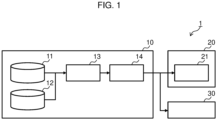
- FIG. 1 is a block diagram illustrating an example of the configuration of the train control system 1 according to an embodiment of the present invention.
- the train control system 1 is configured by having a diagram generating device 10, a train 20, and an operation managing device 30.
- the diagram generating device 10 generates an operation diagram (hereinafter, diagram) by allocating required time to inter-station sections on the basis of the energy characteristics and delay recovery effects, and transmits the generated diagram to the train 20 and the operation managing device 30.
- the diagram generating device 10 has an energy characteristic storing unit 11, a delay recovery effect storing unit 12, a margin time allocation determining unit 13, and a diagram generating unit 14.
- the diagram generating device 10 is realized by, for example, a computer having a processor, a memory, a storage device, and an input/output device.
- the functions of the margin time allocation determining unit 13 and the diagram generating unit 14 are realized when the processor expands a program stored in the storage device or the like to the memory and executes it.
- the functions of the energy characteristic storing unit 11 and the delay recovery effect storing unit 12 are realized by storing predetermined data in the storage device or the memory.
- the energy characteristic storing unit 11 has a function of storing energy characteristic information indicating energy characteristic of each inter-station section with respect to the characteristic of energy (energy characteristic) required by the train 20 traveling between stations.
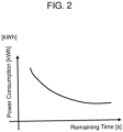
- FIG. 2 is a diagram for explaining the energy characteristics.
- the energy characteristic in the embodiment is expressed by energy (for example, power consumption amount) required by a train traveling in an inter-station section to which margin time is given with respect to the margin time.
- FIG. 2 illustrates the relationship between the margin time on the horizontal axis and the power consumption amount on the vertical axis as an example of general energy characteristics.
- the horizontal axis of FIG. 2 may be required time obtained by adding margin time given to an inter-station section and time (fastest time) required when a train travels at the fastest speed in the inter-station section.
- the diagram generating device 10 preliminarily calculates power consumption amounts for a plurality of margin times for each inter-station section on the basis of past records, or in accordance with simulation or the like, and stores the calculation results as information indicating the energy characteristics (energy characteristic information) into the energy characteristic storing unit 11.
- Another configuration may be employed that the energy characteristic information generated on the outside of the diagram generating device 10 is stored in the energy characteristic storing unit 11.
- the energy characteristic has a tendency that the longer the margin time is given, the more the necessary energy (power consumption amount) decreases.
- the longer the required time obtained by adding fastest time to the margin time is, the more the necessary energy (power consumption amount) decreases.
- the necessary energy decreases, the energy saving effect becomes higher.
- the energy saving effect with respect to the margin time it can be replaced by required time
- the margin time allocation determining unit 13 allocates a longer margin time to an inter-station section having excellent energy saving performance on the basis of the energy characteristic of each of inter-station sections.
- an inter-station section having excellent energy saving performance concretely, an inter-station section having many downward slopes, an inter-station section having a small number of curbs (having many straight paths), an inter-station section whose distance is long, an inter-station section in which limiting speed is high, an uncomplicated inter-station section in which limiting speed is constant, and the like can be assumed.
- the delay recovery effect storing unit 12 has a function of storing delay recovery effect information indicating a delay recovery effect for each of inter-station sections with respect to an effect of recovering a delay (delay recovery effect) in an inter-station section when a delay occurs in the train 20 in the inter-station section.
- delay recovery effect information indicating a delay recovery effect for each of inter-station sections with respect to an effect of recovering a delay (delay recovery effect) in an inter-station section when a delay occurs in the train 20 in the inter-station section.
- an inter-station section having high delay recovery effect is an inter-station section to which longer margin time is allocated when a delay occurs, thereby increasing the probability capable of recovering the delay.
- the delay recovery effect information for example, the following delay recovery effects can be set.
- the delay recovery effect in the inter-station section In the case where an inter-station section in which a delay tends to occur can be assumed, by allocating longer margin time to the inter-station section, the delay recovery becomes easier. Consequently, the delay recovery effect in the inter-station section is set to be high.
- margin time which is used for delay recovery when a delay occurs In the case where an inter-station section in which a delay tends to occur cannot be assumed, by allocating longer margin time to an inter-station section on the termination side, margin time which is used for delay recovery when a delay occurs can be assured. Consequently, the delay recovery effect in the inter-station section on the termination side is set to be high.
- an inter-station section having high delay recovery effect a predetermined number of inter-station sections on the end side of a train line, an inter-station section in which the frequency of occurrence of a delay in the past is high, an inter-station section in which the number of curbs is small, an inter-station section just before a station at which the number of passengers transferring to another line is large, and the like are assumed.
- a concrete value of each of the delay recovery effects in the delay recovery effect information is determined in consideration of operation data in the past and the past experiences of command staffs.
- the delay recovery effect may be set as different values by the time zones.
- the delay recovery effect may be set as different values by the degrees of delay.
- the value of the delay recovery effect which is set in the delay recovery effect information may be a fixed value which is calculated in advance on the basis of the past record or the like or a variable value which is calculated in real time. In the case of changing the value in real time, a setting and a change may be performed in consideration of the operation situation and the congestion situation. Also in the case of using a fixed value, the value may be periodically corrected in accordance with the usage situation of passengers and a change in the environment.
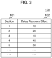
- FIG. 3 is a diagram illustrating an example of delay recovery effect information.
- Delay recovery effect information 100 illustrated in FIG. 3 is an example of the delay recovery effect information stored in the delay recovery effect storing unit 12 and has data fields of fields 101 and 102.
- a plurality of inter-station sections included from the starting station to the end station are indicated in the travel order of the train 20.
- the delay recovery effect in the inter-station section indicated in the field 101 is indicated.
- a record of "1" as the value of the field 101 indicates that the delay recovery effect in the first inter-station section (the section from the starting station to the first station) is "10".
- a record of "2" as the value of the field 101 indicates that the delay recovery effect in the second inter-station section (the section from the first station to the second station) is "20".
- the value of the delay recovery effect which is set in the field 102 is an index value. In the case of the above example, it means that the delay recovery effect in the second inter-station section is twice as high as that in the first inter-station section.
- the margin time allocation determining unit 13 has a function of determining margin time allocated to each inter-station section on the basis of the energy characteristic information stored in the energy characteristic storing unit 11 and the delay recovery effect information stored in the delay recovery effect storing unit 12. Concretely, the margin time allocation determining unit 13 allocates margin time to each of inter-station sections while allocating longer margin time to an inter-station section having excellent energy saving performance on the basis of the energy characteristic indicated by the energy characteristic information, allocates margin time to each of the inter-station sections while allocating longer margin time to an inter-station section having high delay recovery effect on the basis of the delay recovery effect indicated by the delay recovery effect information, and determines total time of those margin times in the inter-station sections as margin time allocated to each of inter-station sections.
- a conventional technique as disclosed in the patent literature 1 can be used.
- the split ratio between the margin time allocated on the basis of the delay recovery effect and the margin time allocated on the basis of the energy characteristic in accordance with requirement specifications of punctuality and the energy saving performance. For example, in the case of placing emphasis on the punctuality, it is sufficient to increase the ratio of the margin time allocated to the delay recovery effect. In the case of placing emphasis on the energy saving performance, it is sufficient to increase the ratio of the margin time allocated to the energy characteristic amount.
- the split ratio of allocating to the energy characteristic may be increased within "the range in which the influence is not exerted on a delay and punctuality" which can be determined by the past record. The reason is that, even when margin time is excessively given to an inter-station section in which a record of delay is little, the actual delay recovery effect is low.
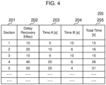
- FIG. 4 is a diagram for explaining allocation of margin time to inter-station sections.
- An allocation time determination table 200 illustrated in FIG. 4 is table data as an example of allocation of margin time to each inter-station section by the margin time allocation determining unit 13, and has data fields 201 to 205.
- the field 201 indicates an inter-station section
- the field 202 indicates a delay recovery effect in the inter-station section indicated in the field 101.
- the values in the fields 201 and 202 are the same as the values in the fields 101 and 102 of the delay recovery effect information 100 illustrated in FIG. 3 .
- the field 203 indicates allocated time (time A) of margin time based on the delay recovery effect.
- the value in the field 203 is calculated when the margin time allocation determining unit 13 allocates margin time which can be allocated as the delay recovery effect amount to each inter-station section in accordance with the delay recovery effect (the value in the field 202) of each inter-station section indicated by the delay recovery effect information.
- the field 204 indicates allocated time (time B) of margin time based on the energy characteristic.
- the value in the field 204 is calculated when the margin time allocation determining unit 13 allocates margin time which can be allocated as the energy characteristic amount to each inter-station section in accordance with the energy characteristic (refer to FIG. 2 ) of each inter-station section indicated in the energy characteristic information.
- the "margin time which can be allocated as the delay recovery effect amount” and the “margin time which can be allocated as the energy characteristic amount” are calculated by splitting the total margin time which can be allocated in accordance with the above-described "split ratio".
- the field 205 indicates the margin time (total time) finally allocated to the inter-station section.
- the value in the field 205 is calculated by totaling the value in the field 203 and the value in the field 204 by the margin time allocation determining unit 13.
- the margin time allocation determining unit 13 can determine allocation of margin time to each inter-station section on the basis of two pieces of restriction information which are the energy characteristic and the delay recovery effect.
- the margin time allocation determining unit 13 is not limited to the determination of the allocation of margin time to each inter-station section on the basis of the two pieces of restriction information which are the energy characteristic and the delay recovery effect, and may determine allocation of margin time to each inter-station section by adding another restriction information or replacing the restriction information with another restriction information.
- the degree of requirement of punctuality according to the number of users may be added.
- a restriction to fix required time or prevent delay is placed on an inter-station section in an inter-station section in which the number of users is large. In this case, it is sufficient to give longer margin time preferentially to an inter-station section within a section in which the passenger demand is high.
- required time may be fixed by giving margin time to the inter-station section in advance and excluding the inter-station section from inter-station sections as objects to which margin time is allocated by the margin time allocation determining unit 13.
- a request to avoid the influence on a following train due to grant of margin time may be added.
- the influence on a following train due to grant of margin time means a situation such that the train 20 travels while reducing speed in an inter-station section to which margin time is granted and, as a result, a following train also has to travel while reducing speed. Therefore, in the case of adding the fourth restriction information, the margin time allocation determining unit 13 has to allocate margin time to each of inter-station sections in the operation of the train 20 while assuring punctuality of a following train.
- a threshold (limit time) of margin time at which the influence on a following train can be avoided can be calculated in advance from record data in the past, simulation, and the like for each inter-station section.
- the margin time allocation determining unit 13 suppresses margin time to be granted.
- longer margin time may be allocated to the inter-station section so that the energy characteristic becomes excellent.
- the above-described another restriction information (third restriction information and the fourth restriction information) may be stored in the energy characteristic storing unit 11 or the delay recovery effect storing unit 12 in the diagram generating device 10.
- the diagram generating unit 14 has a function of generating a diagram on the basis of margin time for each inter-station section determined by the margin time allocation determining unit 13. Concretely, the diagram generating unit 14 sets a value obtained by adding margin time of an inter-station section determined by the margin time allocation determining unit 13 to the highest-speed time in the inter-station section as target travel time (that is, target diagram) in the inter-station section. Since a conventional general diagram generating function can be used for a diagram generating process after a target diagram for each inter-station section is set, detailed description is omitted.
- the train 20 is a railroad vehicle which travels according to the diagram generated by the diagram generating device 10 and has, at least, an operation control device 21.
- the operation control device 21 has a function of controlling travel of the train 20 so as to satisfy target travel time in accordance with the diagram generated by the diagram generating unit 14. Concretely, the operation control device 21 generates a plurality of speed targets (travel patterns) and controls operation of a train so as to follow any of the travel patterns on the basis of the target travel time of the diagram.
- speed targets travel patterns
- the operation control device 30 has a function of managing operation of the train 20.
- the operation managing device 30 controls a ground facility (for example, the direction of a point switch or the like) and controls the track in each station of the train 20 to make the train 20 travel on a railway track designated by the diagram.
- the operation managing device 30 instructs the diagram generating device 10 to re-generate a diagram, and notifies the train 20 of the diagram re-generated by the diagram generating device 10.
- the operation managing device 30 may re-generate a diagram on the basis of the current situation and notify the train 20 of the diagram. In those cases, the operation control device 21 of the train 20 controls travel of the train 20 in accordance with the re-generated diagram.
- Generation of a travel pattern for making the train 20 travel may be calculated by the operation control device 21 as described above, or a result of calculation made by the operation managing device 30 may be notified to the train 20 (the operation control device 21).
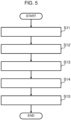
- FIG. 5 is a flowchart illustrating an example of the procedure of a diagram generating process.
- the diagram generating process is executed by the diagram generating device 10.
- the process of FIG. 5 is executed, for example, before start of operation of the train 20.
- the margin time allocation determining unit 13 calculates the total value of margin time of all of inter-station sections in a train line as a target of diagram generation (step S11).
- the margin time allocation determining unit 13 splits, in accordance with a predetermined split ratio, the total value of the margin time calculated in step S11 into margin time to be allocated to the delay recovery effect amount and margin time to be allocated to the energy characteristic amount (step S12).
- the split ratio is determined according to, for example, required specifications of punctuality and energy saving performance. In the case where restriction information other than the energy characteristic and the delay recovery effect exists, the split ratio is determined in consideration of the restriction information as well.
- the margin time allocation determining unit 13 allocates the margin time to be allocated to the delay recovery effect amount calculated in step S12 to the inter-station sections in accordance with the delay recovery effects in the inter-station sections indicated by the delay recovery effect information stored in the delay recovery effect storing unit 12 (step S13).
- the margin time allocation determining unit 13 allocates the margin time to each of the inter-station sections in accordance with the degree of the delay recovery effect (refer to the field 203 in FIG. 4 ).
- the margin time allocation determining unit 13 allocates the margin time to be allocated to the energy characteristic amount calculated in step S12 to each of the inter-station sections in accordance with the energy characteristic of each of the inter-station sections indicated by the energy characteristic information stored in the energy characteristic storing unit 11 (step S14).
- the margin time allocation determining unit 13 allocates the margin time to each of the inter-station sections in accordance with the degree of the energy saving performance (refer to the field 204 in FIG. 4 ).
- the diagram generating unit 14 totals, with respect to each of the inter-station sections, the margin time allocated in step S13, the margin time allocated in step S14, and the fastest time in the inter-station section, and sets the total value as target travel time in the inter-station section to generate a target diagram of the train line (step S15).
- the generated diagram is notified to the train 20 and the operation managing device 30, and the diagram generating process is finished.
- the above is the procedure of generating a diagram in the train control system 1 according to the embodiment. Since the diagram generating process is executed before operation of the train 20 as described above, in allocation of required time while placing emphasis on energy saving performance, at the time of generating a diagram before operation, by allocating longer margin time preferentially to an inter-station section having high delay recovery effect, even if a delay occurs during operation, the probability that the delay can be recovered by using the margin time can be increased, and the effect of maintaining punctuality can be expected.
- the diagram generating process illustrated in FIG. 5 may be executed in the case where a delay occurs during operation of the train 20.
- the margin time allocation determining unit 13 re-allocates the total margin time remaining at the present time point to the inter-station sections.
- the diagram generating unit 14 re-generates a diagram.
- the remaining margin time is collected and re-allocated so as to grant longer margin time preferentially to an inter-station section having high delay recovery effect in consideration of the energy saving performance.
- the required time according to the operation situation can be re-allocated.
- the probability that a delay can be recovered is increased by using the margin time in the following operation, and an effect of maintaining punctuality can be expected.
Landscapes
- Engineering & Computer Science (AREA)
- Mechanical Engineering (AREA)
- Train Traffic Observation, Control, And Security (AREA)
Abstract
Description
- The present invention relates to a diagram generating device, a train control system, and a diagram generating method, and is suitably applied to a diagram generating device, a train control system, and a diagram generating method of generating an operation diagram of a train traveling on a train line.
- In driving of a railroad vehicle (train), the more the required time between stations is granted, the more energy required by a train travelling between the stations decreases and the higher the energy saving effect becomes. There is further a nature that the energy saving effect obtained by grant of required time varies among inter-station sections. There is a known method of improving the energy saving performance without changing the time required for an entire train line by, utilizing this nature, allocating longer required time to an inter-station section in which the energy saving effect is high.
- For example,
patent literature 1 describes a method of, when an operation situation changes, re-generating an operation diagram by re-allocating margin time on the basis of energy saving effects in inter-station sections in which a train travels after the change. - Patent Literature 1:
Japanese Unexamined Patent Application Publication No. 2017-017857 - In the conventional method of allocating longer required time to an inter-station section in which the energy saving effect is high, however, required time which is not so long is allocated to some inter-station sections. There is a problem such that a situation in which, when a delay occurs, it becomes difficult to recover the delay may happen. For example, in the system disclosed in the above-described
patent literature 1, in the case where longer margin time is allocated to inter-station sections before a delay occurs, margin time which can be allocated to inter-station sections in which a train travels after the occurrence of the delay is not assured. There is, consequently, the possibility that the delay cannot be recovered even if the train travels at the highest speed after the occurrence of the delay, and punctuality cannot be maintained. - The present invention has been achieved in consideration of the above point and proposes a diagram generating device, a train control system, and a diagram generating method capable of generating an operation diagram by which punctuality can be easily maintained even in the case where a delay occurs during operation of a train by granting margin time to inter-station sections in consideration of the characteristic of energy necessary for a train travelling between stations and delay recovery effect.
- In order to solve the above problems, the present invention provide a diagram generating device generating an operation diagram of a train travelling on a train line, and the diagram generating device includes: a delay recovery effect storing unit that stores first restriction information indicating an effect capable of recovering a delay when the delay occurs by allocating margin time to each of inter-station sections included in the train line; an energy characteristic storing unit that stores second restriction information indicating a characteristic of energy required by a train traveling on each of the inter-station sections; a margin time allocation determining unit that determines allocation of margin time to each of the inter-station sections by allocating, to each inter-station section, first margin time in total time of margin time which can be allocated to the inter-station sections on the basis of the first restriction information, and allocating second margin time in the total time to each inter-station section on the basis of the second restriction information; and a diagram generating unit that generates an operation diagram of the train on the basis of the margin time for each of the inter-station sections determined by the margin time allocation determining unit.
- Further, in order to solve the above problems, the present invention provide a train control system which includes: a diagram generating device generating an operation diagram of a train travelling on a train line; an operation control device mounted on the train; and an operation management device managing operation of the train. In the train control system, the diagram generating device includes: a delay recovery effect storing unit that stores first restriction information indicating an effect capable of recovering a delay when the delay occurs by allocating margin time to each of inter-station sections included in the train line; an energy characteristic storing unit that stores second restriction information indicating a characteristic of energy required by a train traveling in each of the inter-station sections for each of the inter-station sections; a margin time allocation determining unit that determines allocation of the margin time to each of the inter-station sections by allocating, to each of the inter-station sections, first margin time in total time of margin time which can be allocated to each of the inter-station sections on the basis of the first restriction information and allocating second margin time in the total time to each of the inter-station sections on the basis of the second restriction information; and a diagram generating unit that generates an operation diagram of the train on the basis of the margin time for each of the inter-station sections determined by the margin time allocation determining unit. The operation control device controls travel of the train so as to satisfy target travel time in an inter-station section designated by an operation diagram generated by the diagram generating unit, and the operation managing device controls operation and a track of the train on the basis of the operation diagram generated by the diagram generating unit.
- Further, in order to solve the above problems, the present invention provide a diagram generating method by a diagram generating device generating an operation diagram of a train travelling on a train line. In the diagram generating method, the diagram generating device includes: a delay recovery effect storing unit that stores first restriction information indicating an effect capable of recovering a delay when the delay occurs by allocating margin time to each of inter-station sections included in the train line; an energy characteristic storing unit that stores second restriction information indicating a characteristic of energy required by a train traveling in each of the inter-station sections for each of the inter-station sections; a margin time allocation determining unit that determines allocation of margin time for each of the inter-station sections; and a diagram generating unit generating an operation diagram of the train. The diagram generating method includes: a margin time allocation step of determining allocation of margin time to each of the inter-station sections, by the margin time allocation determining unit, by allocating first margin time in total time of margin time which can be allocated to the inter-station sections to each of the inter-station sections on the basis of the first restriction information, and allocating second margin time in the total time to each of the inter-station sections on the basis of the second restriction information; and a diagram generation step of, by the diagram generating unit, generating an operation diagram of the train on the basis of the margin time for each of the inter-station sections determined in the margin time allocation step.
- According to the present invention, it is possible to generate an operation diagram in which punctuality can be easily maintained even in the case where a delay occurs during operation of a train.
-
-
FIG. 1 is a block diagram illustrating a configuration example of atrain control system 1 according to an embodiment of the present invention. -
FIG. 2 is a diagram for explaining energy characteristics. -
FIG. 3 is a diagram illustrating an example of delay recovery effect information. -
FIG. 4 is a diagram for explaining allocation of margin time to distances between stations. -
FIG. 5 is a flowchart illustrating a process procedure example of a diagram generating process. - Embodiments of the present invention will now be described with reference to the drawings.
- The following description and the drawings are an example for explaining the present invention. To clarify the description, omission and simplification are made properly. All of combinations of characteristics described in the embodiment are not always necessary for means for solving the invention. The present invention is not limited to the embodiment. All of application examples matching the idea of the present invention are included in the technical scope of the present invention. In the present invention, a person skilled in the art can perform various additions, changes, and the like within the scope of the present invention. The present invention can be also carried out in other various modes. Unless otherwise limited, the number of components may be plural or single.
- In the following description, there is the case of explaining processes performed by executing a program. When a program is executed by at least one processor (for example, a CPU) or more, predetermined process is performed by properly using a storage resource (for example, a memory) and/or an interface device (for example, a communication port) or the like. Consequently, the main body of the process may be a processor. Similarly, the main body of a process performed by executing a program may be a controller, a device, a system, a computer, a node, a storage system, a storage device, a server, a managing computer, a client, or a host having a processor. The main body (for example, a processor) of process performed by executing a program may include a hardware circuit performing a part or all of the process. For example, the main body of the process performed by executing a program may include a hardware circuit executing encryption and decryption or compression and decompression. The processor operates as function units realizing predetermined functions by operating according to a program. A device and a system including the processor are a device and a system including the function units.
- The program may be installed from a program source to a device such as a computer. The program source may be, for example, a storage medium which can be read by a program distribution server or a computer. In the case where the program source is a program distribution server, the program distribution server may include a processor (for example, a CPU) and a storage resource, and the storage resource may further store a distribution program and a program to be distributed. When the processor of the program distribution server executes the distribution program, the processor of the program distribution server may distribute a program to be distributed to another computer. In the following description, two or more programs may be realized as one program, or one program may be realized as two or more programs.
- In the following description, characteristics between stations will be expressed like "an inter-station section having long inter-station distance" or "an inter-station section in which regulation speed is high". In the case where a target to be compared is not clearly described, those characteristics may use, as a reference, an average value in inter-station sections, a predetermined threshold, or a threshold determined by a predetermined calculation method.
- First, components of a
train control system 1 according to an embodiment of the present invention, and the functions of the components will be described. -
FIG. 1 is a block diagram illustrating an example of the configuration of thetrain control system 1 according to an embodiment of the present invention. As illustrated inFIG. 1 , thetrain control system 1 is configured by having a diagram generatingdevice 10, atrain 20, and anoperation managing device 30. As the details will be described later, in thetrain control system 1, the diagram generatingdevice 10 generates an operation diagram (hereinafter, diagram) by allocating required time to inter-station sections on the basis of the energy characteristics and delay recovery effects, and transmits the generated diagram to thetrain 20 and theoperation managing device 30. - The
diagram generating device 10 has an energycharacteristic storing unit 11, a delay recoveryeffect storing unit 12, a margin timeallocation determining unit 13, and adiagram generating unit 14. - The diagram generating
device 10 is realized by, for example, a computer having a processor, a memory, a storage device, and an input/output device. In this case, the functions of the margin timeallocation determining unit 13 and thediagram generating unit 14 are realized when the processor expands a program stored in the storage device or the like to the memory and executes it. The functions of the energycharacteristic storing unit 11 and the delay recoveryeffect storing unit 12 are realized by storing predetermined data in the storage device or the memory. - The energy
characteristic storing unit 11 has a function of storing energy characteristic information indicating energy characteristic of each inter-station section with respect to the characteristic of energy (energy characteristic) required by thetrain 20 traveling between stations. -
FIG. 2 is a diagram for explaining the energy characteristics. The energy characteristic in the embodiment is expressed by energy (for example, power consumption amount) required by a train traveling in an inter-station section to which margin time is given with respect to the margin time.FIG. 2 illustrates the relationship between the margin time on the horizontal axis and the power consumption amount on the vertical axis as an example of general energy characteristics. The horizontal axis ofFIG. 2 may be required time obtained by adding margin time given to an inter-station section and time (fastest time) required when a train travels at the fastest speed in the inter-station section. - The result of the power consumption amount varies depending on the margin time, and also varies depending on an inter-station section. Consequently, the
diagram generating device 10 preliminarily calculates power consumption amounts for a plurality of margin times for each inter-station section on the basis of past records, or in accordance with simulation or the like, and stores the calculation results as information indicating the energy characteristics (energy characteristic information) into the energycharacteristic storing unit 11. Another configuration may be employed that the energy characteristic information generated on the outside of thediagram generating device 10 is stored in the energycharacteristic storing unit 11. - As illustrated in
FIG. 2 , generally, the energy characteristic has a tendency that the longer the margin time is given, the more the necessary energy (power consumption amount) decreases. In other words, there is a tendency that the longer the required time obtained by adding fastest time to the margin time is, the more the necessary energy (power consumption amount) decreases. When the necessary energy decreases, the energy saving effect becomes higher. Further, there is a known nature such that the energy saving effect with respect to the margin time (it can be replaced by required time) varies among inter-station sections. - In consideration of the characteristic and the nature, the margin time
allocation determining unit 13 allocates a longer margin time to an inter-station section having excellent energy saving performance on the basis of the energy characteristic of each of inter-station sections. As the "inter-station section having excellent energy saving performance", concretely, an inter-station section having many downward slopes, an inter-station section having a small number of curbs (having many straight paths), an inter-station section whose distance is long, an inter-station section in which limiting speed is high, an uncomplicated inter-station section in which limiting speed is constant, and the like can be assumed. - The delay recovery
effect storing unit 12 has a function of storing delay recovery effect information indicating a delay recovery effect for each of inter-station sections with respect to an effect of recovering a delay (delay recovery effect) in an inter-station section when a delay occurs in thetrain 20 in the inter-station section. In the embodiment, an inter-station section having high delay recovery effect is an inter-station section to which longer margin time is allocated when a delay occurs, thereby increasing the probability capable of recovering the delay. - As the delay recovery effect information, for example, the following delay recovery effects can be set. In the case where an inter-station section in which a delay tends to occur can be assumed, by allocating longer margin time to the inter-station section, the delay recovery becomes easier. Consequently, the delay recovery effect in the inter-station section is set to be high. In the case where an inter-station section in which a delay tends to occur cannot be assumed, by allocating longer margin time to an inter-station section on the termination side, margin time which is used for delay recovery when a delay occurs can be assured. Consequently, the delay recovery effect in the inter-station section on the termination side is set to be high. Therefore, as examples of an inter-station section having high delay recovery effect, a predetermined number of inter-station sections on the end side of a train line, an inter-station section in which the frequency of occurrence of a delay in the past is high, an inter-station section in which the number of curbs is small, an inter-station section just before a station at which the number of passengers transferring to another line is large, and the like are assumed.
- A concrete value of each of the delay recovery effects in the delay recovery effect information is determined in consideration of operation data in the past and the past experiences of command staffs. In the case where the delay recovery effect varies depending on the time zones such as rush hour in the morning and off-time in the daytime, the delay recovery effects may be set as different values by the time zones. In the case where the delay recovery effect varies depending on the degree of a delay which occurs, the delay recovery effect may be set as different values by the degrees of delay.
- The value of the delay recovery effect which is set in the delay recovery effect information may be a fixed value which is calculated in advance on the basis of the past record or the like or a variable value which is calculated in real time. In the case of changing the value in real time, a setting and a change may be performed in consideration of the operation situation and the congestion situation. Also in the case of using a fixed value, the value may be periodically corrected in accordance with the usage situation of passengers and a change in the environment.
-
FIG. 3 is a diagram illustrating an example of delay recovery effect information. Delayrecovery effect information 100 illustrated inFIG. 3 is an example of the delay recovery effect information stored in the delay recoveryeffect storing unit 12 and has data fields offields - In
FIG. 3 , in thefield 101, a plurality of inter-station sections included from the starting station to the end station are indicated in the travel order of thetrain 20. In thefield 102, the delay recovery effect in the inter-station section indicated in thefield 101 is indicated. Concretely, for example, in the case ofFIG. 3 , a record of "1" as the value of thefield 101 indicates that the delay recovery effect in the first inter-station section (the section from the starting station to the first station) is "10". A record of "2" as the value of thefield 101 indicates that the delay recovery effect in the second inter-station section (the section from the first station to the second station) is "20". The value of the delay recovery effect which is set in thefield 102 is an index value. In the case of the above example, it means that the delay recovery effect in the second inter-station section is twice as high as that in the first inter-station section. - The margin time
allocation determining unit 13 has a function of determining margin time allocated to each inter-station section on the basis of the energy characteristic information stored in the energycharacteristic storing unit 11 and the delay recovery effect information stored in the delay recoveryeffect storing unit 12. Concretely, the margin timeallocation determining unit 13 allocates margin time to each of inter-station sections while allocating longer margin time to an inter-station section having excellent energy saving performance on the basis of the energy characteristic indicated by the energy characteristic information, allocates margin time to each of the inter-station sections while allocating longer margin time to an inter-station section having high delay recovery effect on the basis of the delay recovery effect indicated by the delay recovery effect information, and determines total time of those margin times in the inter-station sections as margin time allocated to each of inter-station sections. In the allocation of margin time based on the energy characteristic, a conventional technique as disclosed in thepatent literature 1 can be used. - It is sufficient to determine the split ratio between the margin time allocated on the basis of the delay recovery effect and the margin time allocated on the basis of the energy characteristic in accordance with requirement specifications of punctuality and the energy saving performance. For example, in the case of placing emphasis on the punctuality, it is sufficient to increase the ratio of the margin time allocated to the delay recovery effect. In the case of placing emphasis on the energy saving performance, it is sufficient to increase the ratio of the margin time allocated to the energy characteristic amount. The split ratio of allocating to the energy characteristic may be increased within "the range in which the influence is not exerted on a delay and punctuality" which can be determined by the past record. The reason is that, even when margin time is excessively given to an inter-station section in which a record of delay is little, the actual delay recovery effect is low.
-
FIG. 4 is a diagram for explaining allocation of margin time to inter-station sections. An allocation time determination table 200 illustrated inFIG. 4 is table data as an example of allocation of margin time to each inter-station section by the margin timeallocation determining unit 13, and hasdata fields 201 to 205. - In
FIG. 4 , thefield 201 indicates an inter-station section, and thefield 202 indicates a delay recovery effect in the inter-station section indicated in thefield 101. The values in thefields fields recovery effect information 100 illustrated inFIG. 3 . - The
field 203 indicates allocated time (time A) of margin time based on the delay recovery effect. The value in thefield 203 is calculated when the margin timeallocation determining unit 13 allocates margin time which can be allocated as the delay recovery effect amount to each inter-station section in accordance with the delay recovery effect (the value in the field 202) of each inter-station section indicated by the delay recovery effect information. - The
field 204 indicates allocated time (time B) of margin time based on the energy characteristic. The value in thefield 204 is calculated when the margin timeallocation determining unit 13 allocates margin time which can be allocated as the energy characteristic amount to each inter-station section in accordance with the energy characteristic (refer toFIG. 2 ) of each inter-station section indicated in the energy characteristic information. - The "margin time which can be allocated as the delay recovery effect amount" and the "margin time which can be allocated as the energy characteristic amount" are calculated by splitting the total margin time which can be allocated in accordance with the above-described "split ratio".
- The
field 205 indicates the margin time (total time) finally allocated to the inter-station section. The value in thefield 205 is calculated by totaling the value in thefield 203 and the value in thefield 204 by the margin timeallocation determining unit 13. - As described above, as illustrated in
FIG. 4 , the margin timeallocation determining unit 13 can determine allocation of margin time to each inter-station section on the basis of two pieces of restriction information which are the energy characteristic and the delay recovery effect. - In the embodiment, the margin time
allocation determining unit 13 is not limited to the determination of the allocation of margin time to each inter-station section on the basis of the two pieces of restriction information which are the energy characteristic and the delay recovery effect, and may determine allocation of margin time to each inter-station section by adding another restriction information or replacing the restriction information with another restriction information. - For example, as third restriction information, the degree of requirement of punctuality according to the number of users (the number of passengers) may be added. Concretely, a restriction to fix required time or prevent delay is placed on an inter-station section in an inter-station section in which the number of users is large. In this case, it is sufficient to give longer margin time preferentially to an inter-station section within a section in which the passenger demand is high. With respect to an inter-station section in the section in which the passenger demand is high, required time may be fixed by giving margin time to the inter-station section in advance and excluding the inter-station section from inter-station sections as objects to which margin time is allocated by the margin time
allocation determining unit 13. - For example, as fourth restriction information, a request to avoid the influence on a following train due to grant of margin time may be added. The influence on a following train due to grant of margin time means a situation such that the
train 20 travels while reducing speed in an inter-station section to which margin time is granted and, as a result, a following train also has to travel while reducing speed. Therefore, in the case of adding the fourth restriction information, the margin timeallocation determining unit 13 has to allocate margin time to each of inter-station sections in the operation of thetrain 20 while assuring punctuality of a following train. A threshold (limit time) of margin time at which the influence on a following train can be avoided can be calculated in advance from record data in the past, simulation, and the like for each inter-station section. - In the case of employing the fourth restriction information, for an inter-station section in which the influence tends to be exerted on a following train, it is considered that the margin time
allocation determining unit 13 suppresses margin time to be granted. On the contrary, under a condition that a delay is allowed within a range of exerting no influence on a following train, longer margin time may be allocated to the inter-station section so that the energy characteristic becomes excellent. As a result of the above, while maintaining punctuality of a following train, the delay recovery effect or energy characteristic (energy saving effect) in the present train can be increased. - The above-described another restriction information (third restriction information and the fourth restriction information) may be stored in the energy
characteristic storing unit 11 or the delay recoveryeffect storing unit 12 in thediagram generating device 10. - The
diagram generating unit 14 has a function of generating a diagram on the basis of margin time for each inter-station section determined by the margin timeallocation determining unit 13. Concretely, thediagram generating unit 14 sets a value obtained by adding margin time of an inter-station section determined by the margin timeallocation determining unit 13 to the highest-speed time in the inter-station section as target travel time (that is, target diagram) in the inter-station section. Since a conventional general diagram generating function can be used for a diagram generating process after a target diagram for each inter-station section is set, detailed description is omitted. - The
train 20 is a railroad vehicle which travels according to the diagram generated by thediagram generating device 10 and has, at least, anoperation control device 21. - The
operation control device 21 has a function of controlling travel of thetrain 20 so as to satisfy target travel time in accordance with the diagram generated by thediagram generating unit 14. Concretely, theoperation control device 21 generates a plurality of speed targets (travel patterns) and controls operation of a train so as to follow any of the travel patterns on the basis of the target travel time of the diagram. - The
operation control device 30 has a function of managing operation of thetrain 20. For example, theoperation managing device 30 controls a ground facility (for example, the direction of a point switch or the like) and controls the track in each station of thetrain 20 to make thetrain 20 travel on a railway track designated by the diagram. In the case where a fluctuation occurs in the operation situation due to a delay of a preceding train or the like and a change from the diagram generated first becomes necessary, theoperation managing device 30 instructs thediagram generating device 10 to re-generate a diagram, and notifies thetrain 20 of the diagram re-generated by thediagram generating device 10. Alternatively, theoperation managing device 30 may re-generate a diagram on the basis of the current situation and notify thetrain 20 of the diagram. In those cases, theoperation control device 21 of thetrain 20 controls travel of thetrain 20 in accordance with the re-generated diagram. - Generation of a travel pattern for making the
train 20 travel may be calculated by theoperation control device 21 as described above, or a result of calculation made by theoperation managing device 30 may be notified to the train 20 (the operation control device 21). - Next, the diagram generating procedure in the
train control system 1 according to the embodiment will be described. -
FIG. 5 is a flowchart illustrating an example of the procedure of a diagram generating process. The diagram generating process is executed by thediagram generating device 10. The process ofFIG. 5 is executed, for example, before start of operation of thetrain 20. - According to
FIG. 5 , first, the margin timeallocation determining unit 13 calculates the total value of margin time of all of inter-station sections in a train line as a target of diagram generation (step S11). - Subsequently, the margin time
allocation determining unit 13 splits, in accordance with a predetermined split ratio, the total value of the margin time calculated in step S11 into margin time to be allocated to the delay recovery effect amount and margin time to be allocated to the energy characteristic amount (step S12). As described above, the split ratio is determined according to, for example, required specifications of punctuality and energy saving performance. In the case where restriction information other than the energy characteristic and the delay recovery effect exists, the split ratio is determined in consideration of the restriction information as well. - Subsequently, the margin time
allocation determining unit 13 allocates the margin time to be allocated to the delay recovery effect amount calculated in step S12 to the inter-station sections in accordance with the delay recovery effects in the inter-station sections indicated by the delay recovery effect information stored in the delay recovery effect storing unit 12 (step S13). In step S13, in allocation of the margin time to all of inter-station sections, the margin timeallocation determining unit 13 allocates the margin time to each of the inter-station sections in accordance with the degree of the delay recovery effect (refer to thefield 203 inFIG. 4 ). - Subsequently, the margin time
allocation determining unit 13 allocates the margin time to be allocated to the energy characteristic amount calculated in step S12 to each of the inter-station sections in accordance with the energy characteristic of each of the inter-station sections indicated by the energy characteristic information stored in the energy characteristic storing unit 11 (step S14). In step S14, in allocation of the margin time to all of the inter-station sections, the margin timeallocation determining unit 13 allocates the margin time to each of the inter-station sections in accordance with the degree of the energy saving performance (refer to thefield 204 inFIG. 4 ). - Subsequently, the
diagram generating unit 14 totals, with respect to each of the inter-station sections, the margin time allocated in step S13, the margin time allocated in step S14, and the fastest time in the inter-station section, and sets the total value as target travel time in the inter-station section to generate a target diagram of the train line (step S15). The generated diagram is notified to thetrain 20 and theoperation managing device 30, and the diagram generating process is finished. - The above is the procedure of generating a diagram in the
train control system 1 according to the embodiment. Since the diagram generating process is executed before operation of thetrain 20 as described above, in allocation of required time while placing emphasis on energy saving performance, at the time of generating a diagram before operation, by allocating longer margin time preferentially to an inter-station section having high delay recovery effect, even if a delay occurs during operation, the probability that the delay can be recovered by using the margin time can be increased, and the effect of maintaining punctuality can be expected. - The diagram generating process illustrated in
FIG. 5 may be executed in the case where a delay occurs during operation of thetrain 20. In this case, to the inter-station sections included in the remaining section at the present time point (that is, each of the inter-station sections from the present location point of thetrain 20 to the end terminal) as targets to which the margin time is to be given, the margin timeallocation determining unit 13 re-allocates the total margin time remaining at the present time point to the inter-station sections. On the basis of the margin time re-allocated to the inter-station sections and the fastest time, thediagram generating unit 14 re-generates a diagram. By executing the diagram generating process during the operation of thetrain 20 as described above, the remaining margin time is collected and re-allocated so as to grant longer margin time preferentially to an inter-station section having high delay recovery effect in consideration of the energy saving performance. In such a manner, the required time according to the operation situation can be re-allocated. The probability that a delay can be recovered is increased by using the margin time in the following operation, and an effect of maintaining punctuality can be expected. -
- 1: train control system
- 10: diagram generating device
- 11: energy characteristic storing unit
- 12: delay recovery effect storing unit
- 13: margin time allocation determining unit
- 14: diagram generating unit
- 20: train
- 21: operation control device
- 30: operation managing device
Claims (11)
- A diagram generating device generating an operation diagram of a train travelling on a train line, comprising:a delay recovery effect storing unit that stores first restriction information indicating an effect capable of recovering a delay when the delay occurs by allocating margin time to each of inter-station sections included in the train line;an energy characteristic storing unit that stores second restriction information indicating a characteristic of energy required by a train traveling on each of the inter-station sections;a margin time allocation determining unit that determines allocation of margin time to each of the inter-station sections by allocating, to each inter-station section, first margin time in total time of margin time which can be allocated to the inter-station sections on the basis of the first restriction information, and allocating second margin time in the total time to each inter-station section on the basis of the second restriction information; anda diagram generating unit that generates an operation diagram of the train on the basis of the margin time for each of the inter-station sections determined by the margin time allocation determining unit.
- The diagram generating device according to claim 1, whereinthe margin time allocation determining unitdetermines the first margin time and the second margin time from the total time in accordance with a ratio determined by a predetermined method,allocates the first margin time to each of the inter-station sections so that longer margin time is granted to an inter-station section in which an effect capable recovering the delay is high, on the basis of the first restriction information, andallocates the second margin time to each of the inter-station sections so that longer margin time is granted to an inter-station section in which the energy saving performance is high, on the basis of the second restriction information.
- The diagram generating device according to claim 2, wherein
the first restriction information is that an inter-station section on the end point side of the train line is an inter-station section in which an effect capable of recovering the delay is high. - The diagram generating device according to claim 2, wherein
the first restriction information is that an inter-station section in which frequency of occurrence of a delay in the past is high is an inter-station section in which an effect capable of recovering the delay is high. - The diagram generating device according to claim 2, wherein
the first restriction information is that an inter-station section before a station where the number of transfers to another train line is large is an inter-station section in which an effect capable of recovering the delay is high. - The diagram generating device according to claim 2, wherein
the margin time allocation determining unit determines the ratio of determining the first margin time and the second margin time from the total time in accordance with a specification of requiring punctuality or energy saving performance. - The diagram generating device according to claim 1, further comprisingthird restriction information indicating the degree of requirement of punctuality according to the number of users of the train, whereinthe margin time allocation determining unit allocates the margin time so that required time in an inter-station section within a section in which the number of users is large is fixed or does not increase on the basis of the third restriction information.
- The diagram generating device according to claim 1, further comprisingfourth restriction information indicating limit time which does not exert influence on a following train due to allocation of margin time to each of the inter-station sections, whereinthe margin time allocation determining unit determines allocation of margin time to each of the inter-station sections within a range of the limit time on the basis of the fourth restriction information.
- The diagram generating device according to claim 1, whereinwhen a delay occurs during operation of the train, the margin time allocation determining unit determines, with inter-station sections included in the remaining section of the train line at the present time point being as targets of allocation of margin time, to re-allocate toral time of margin time allocated to the inter-station sections as the targets of allocation on the basis of the first and second restriction information, andthe diagram generating unit re-generates an operation diagram of the train on the basis of the margin time for each of the inter-station sections to which the re-allocation is determined.
- A train control system comprising:a diagram generating device generating an operation diagram of a train travelling on a train line;an operation control device mounted on the train; andan operation management device managing operation of the train, whereinthe diagram generating device comprises:a delay recovery effect storing unit that stores first restriction information indicating an effect capable of recovering a delay when the delay occurs by allocating margin time to each of inter-station sections included in the train line;an energy characteristic storing unit that stores second restriction information indicating a characteristic of energy required by a train traveling in each of the inter-station sections for each of the inter-station sections;a margin time allocation determining unit that determines allocation of the margin time to each of the inter-station sections by allocating, to each of the inter-station sections, first margin time in total time of margin time which can be allocated to each of the inter-station sections on the basis of the first restriction information and allocating second margin time in the total time to each of the inter-station sections on the basis of the second restriction information; anda diagram generating unit that generates an operation diagram of the train on the basis of the margin time for each of the inter-station sections determined by the margin time allocation determining unit,the operation control device controls travel of the train so as to satisfy target travel time in an inter-station section designated by an operation diagram generated by the diagram generating unit, andthe operation managing device controls operation and a track of the train on the basis of the operation diagram generated by the diagram generating unit.
- A diagram generating method by a diagram generating device generating an operation diagram of a train travelling on a train line,
the diagram generating device comprising:a delay recovery effect storing unit that stores first restriction information indicating an effect capable of recovering a delay when the delay occurs by allocating margin time to each of inter-station sections included in the train line;an energy characteristic storing unit that stores second restriction information indicating a characteristic of energy required by a train traveling in each of the inter-station sections for each of the inter-station sections;a margin time allocation determining unit that determines allocation of margin time for each of the inter-station sections; anda diagram generating unit generating an operation diagram of the train,the method comprising:a margin time allocation step of determining allocation of margin time to each of the inter-station sections, by the margin time allocation determining unit, by allocating first margin time in total time of margin time which can be allocated to the inter-station sections to each of the inter-station sections on the basis of the first restriction information, and allocating second margin time in the total time to each of the inter-station sections on the basis of the second restriction information; anda diagram generation step of, by the diagram generating unit, generating an operation diagram of the train on the basis of the margin time for each of the inter-station sections determined in the margin time allocation step.
Applications Claiming Priority (2)
| Application Number | Priority Date | Filing Date | Title |
|---|---|---|---|
| JP2022065852A JP7824142B2 (en) | 2022-04-12 | 2022-04-12 | Diagram creation device, train control system, and diagram creation method |
| PCT/JP2023/011564 WO2023199720A1 (en) | 2022-04-12 | 2023-03-23 | Timetable creating device, train control system, and timetable creating method |
Publications (2)
| Publication Number | Publication Date |
|---|---|
| EP4509383A1 true EP4509383A1 (en) | 2025-02-19 |
| EP4509383A4 EP4509383A4 (en) | 2026-04-08 |
Family
ID=88329507
Family Applications (1)
| Application Number | Title | Priority Date | Filing Date |
|---|---|---|---|
| EP23788140.4A Pending EP4509383A4 (en) | 2022-04-12 | 2023-03-23 | TIMETABLE GENERATION DEVICE, TRAIN CONTROL SYSTEM AND TIMETABLE GENERATION METHOD |
Country Status (3)
| Country | Link |
|---|---|
| EP (1) | EP4509383A4 (en) |
| JP (1) | JP7824142B2 (en) |
| WO (1) | WO2023199720A1 (en) |
Family Cites Families (5)
| Publication number | Priority date | Publication date | Assignee | Title |
|---|---|---|---|---|
| JP2011173529A (en) | 2010-02-25 | 2011-09-08 | Hitachi Ltd | Computer and method for operation arrangement according to train congestion status |
| JP6453536B2 (en) | 2013-12-03 | 2019-01-16 | 株式会社東芝 | Train operation control device, control method, and control program |
| WO2016084197A1 (en) * | 2014-11-27 | 2016-06-02 | 三菱電機株式会社 | Train operation interval control system, and train operation interval control device |
| JP6552891B2 (en) | 2015-06-30 | 2019-07-31 | 株式会社東芝 | On-board system and ground system |
| JP2017210181A (en) | 2016-05-27 | 2017-11-30 | 株式会社日立製作所 | Target diagram creation device and target diagram creation method |
-
2022
- 2022-04-12 JP JP2022065852A patent/JP7824142B2/en active Active
-
2023
- 2023-03-23 EP EP23788140.4A patent/EP4509383A4/en active Pending
- 2023-03-23 WO PCT/JP2023/011564 patent/WO2023199720A1/en not_active Ceased
Also Published As
| Publication number | Publication date |
|---|---|
| JP7824142B2 (en) | 2026-03-04 |
| JP2023156158A (en) | 2023-10-24 |
| WO2023199720A1 (en) | 2023-10-19 |
| EP4509383A4 (en) | 2026-04-08 |
Similar Documents
| Publication | Publication Date | Title |
|---|---|---|
| CN110427284B (en) | Data processing method, distributed system, computer system, and medium | |
| KR101644569B1 (en) | Apparatus and method for managing virtual processing unit | |
| CN101661486B (en) | Method and system for fragment sorting for hard disk of host comprising virtual computer | |
| CN109788325B (en) | Video task allocation method and server | |
| CN114780014B (en) | Method, electronic device and computer program product for managing metadata storage units | |
| CN114661497B (en) | Operating system partition shared memory method and system | |
| KR102251863B1 (en) | Task allocation method for vehicle cloud computing and server and vehicle data processing system performing the same | |
| CN112631994A (en) | Data migration method and system | |
| JP6736392B2 (en) | Travel pattern creation device and travel pattern creation method | |
| JP7824142B2 (en) | Diagram creation device, train control system, and diagram creation method | |
| CN112748858A (en) | Method, electronic device and computer program product for managing disk array | |
| JP5787844B2 (en) | Radio base station, train management system, and slot allocation method | |
| KR102002246B1 (en) | Method and apparatus for allocating resource for big data process | |
| JP2024158090A (en) | STORAGE SYSTEM AND METHOD FOR CONTROLLING STORAGE SYSTEM - Patent application | |
| KR102484737B1 (en) | Method for selecting distributed message buffer partition of data in mobile IoT environment | |
| US12367075B2 (en) | In-vehicle device, vehicle management system, resource management method, and resource management program for allocation of computing recourses based on a usage state | |
| JPWO2016139709A1 (en) | Train operation management system, train operation management method, and train operation management program | |
| CN110633142B (en) | Block chain consensus method, management node, electronic device, and storage medium | |
| JP2022097855A (en) | Operation plan creation device and operation plan creation method | |
| CN114138400A (en) | Resource scheduling system and method | |
| EP4311159A1 (en) | Method and system for managing a cluster of processing units for the solution of a cryptographic problem | |
| US20250378016A1 (en) | Apparatus for managing storage system | |
| KR20210119528A (en) | Information processing apparatus, information processing method, and information processing program stored in a recording medium | |
| KR101402954B1 (en) | Apparatus and method for allocating dynamic resource in multi-hop system | |
| JP2020057980A (en) | Train wireless communication system |
Legal Events
| Date | Code | Title | Description |
|---|---|---|---|
| STAA | Information on the status of an ep patent application or granted ep patent |
Free format text: STATUS: THE INTERNATIONAL PUBLICATION HAS BEEN MADE |
|
| PUAI | Public reference made under article 153(3) epc to a published international application that has entered the european phase |
Free format text: ORIGINAL CODE: 0009012 |
|
| STAA | Information on the status of an ep patent application or granted ep patent |
Free format text: STATUS: REQUEST FOR EXAMINATION WAS MADE |
|
| 17P | Request for examination filed |
Effective date: 20241112 |
|
| AK | Designated contracting states |
Kind code of ref document: A1 Designated state(s): AL AT BE BG CH CY CZ DE DK EE ES FI FR GB GR HR HU IE IS IT LI LT LU LV MC ME MK MT NL NO PL PT RO RS SE SI SK SM TR |
|
| DAV | Request for validation of the european patent (deleted) | ||
| DAX | Request for extension of the european patent (deleted) | ||
| A4 | Supplementary search report drawn up and despatched |
Effective date: 20260306 |
|
| RIC1 | Information provided on ipc code assigned before grant |
Ipc: B61L 27/12 20220101AFI20260302BHEP Ipc: B61L 27/14 20220101ALI20260302BHEP Ipc: B61L 27/16 20220101ALI20260302BHEP |