EP4509381A1 - Improved noise damper, in particular for an air conditioning system of a railway vehicle - Google Patents
Improved noise damper, in particular for an air conditioning system of a railway vehicle Download PDFInfo
- Publication number
- EP4509381A1 EP4509381A1 EP23306390.8A EP23306390A EP4509381A1 EP 4509381 A1 EP4509381 A1 EP 4509381A1 EP 23306390 A EP23306390 A EP 23306390A EP 4509381 A1 EP4509381 A1 EP 4509381A1
- Authority
- EP
- European Patent Office
- Prior art keywords
- noise damper
- longitudinal direction
- air conditioning
- conditioning system
- railway vehicle
- Prior art date
- Legal status (The legal status is an assumption and is not a legal conclusion. Google has not performed a legal analysis and makes no representation as to the accuracy of the status listed.)
- Granted
Links
Images
Classifications
-
- B—PERFORMING OPERATIONS; TRANSPORTING
- B61—RAILWAYS
- B61D—BODY DETAILS OR KINDS OF RAILWAY VEHICLES
- B61D27/00—Heating, cooling, ventilating, or air-conditioning
-
- F—MECHANICAL ENGINEERING; LIGHTING; HEATING; WEAPONS; BLASTING
- F24—HEATING; RANGES; VENTILATING
- F24F—AIR-CONDITIONING; AIR-HUMIDIFICATION; VENTILATION; USE OF AIR CURRENTS FOR SCREENING
- F24F13/00—Details common to, or for air-conditioning, air-humidification, ventilation or use of air currents for screening
- F24F13/24—Means for preventing or suppressing noise
-
- B—PERFORMING OPERATIONS; TRANSPORTING
- B61—RAILWAYS
- B61D—BODY DETAILS OR KINDS OF RAILWAY VEHICLES
- B61D27/00—Heating, cooling, ventilating, or air-conditioning
- B61D27/0018—Air-conditioning means, i.e. combining at least two of the following ways of treating or supplying air, namely heating, cooling or ventilating
-
- F—MECHANICAL ENGINEERING; LIGHTING; HEATING; WEAPONS; BLASTING
- F24—HEATING; RANGES; VENTILATING
- F24F—AIR-CONDITIONING; AIR-HUMIDIFICATION; VENTILATION; USE OF AIR CURRENTS FOR SCREENING
- F24F13/00—Details common to, or for air-conditioning, air-humidification, ventilation or use of air currents for screening
- F24F13/08—Air-flow control members, e.g. louvres, grilles, flaps or guide plates
-
- F—MECHANICAL ENGINEERING; LIGHTING; HEATING; WEAPONS; BLASTING
- F24—HEATING; RANGES; VENTILATING
- F24F—AIR-CONDITIONING; AIR-HUMIDIFICATION; VENTILATION; USE OF AIR CURRENTS FOR SCREENING
- F24F13/00—Details common to, or for air-conditioning, air-humidification, ventilation or use of air currents for screening
- F24F13/24—Means for preventing or suppressing noise
- F24F2013/242—Sound-absorbing material
-
- F—MECHANICAL ENGINEERING; LIGHTING; HEATING; WEAPONS; BLASTING
- F24—HEATING; RANGES; VENTILATING
- F24F—AIR-CONDITIONING; AIR-HUMIDIFICATION; VENTILATION; USE OF AIR CURRENTS FOR SCREENING
- F24F2221/00—Details or features not otherwise provided for
- F24F2221/46—Air flow forming a vortex
Definitions
- the present invention concerns a noise damper, in particular for an air conditioning system, preferentially in a railway vehicle.
- the main noise source equipment inside a railway vehicle passenger area is generally the air conditioning system HVAC (Heating Ventilation Air Conditioning Unit), and especially the fans which blow the air inside air ducts and towards the passenger area.
- HVAC Heating Ventilation Air Conditioning Unit
- noise damper is already known from prior art. Such a noise damper is intended to equip the air conditioning system, and is arranged between a front air blower of the air conditioning system and the beginning of an air duct. The main function of the noise damper is to absorb the noise coming from the HVAC, and also to share the air in different directions.
- a known noise damper usually comprises a casing, for example made of aluminum, delimiting an air passage, the casing having walls each comprising an acoustic insulation layer.
- the acoustic insulation layers are for example made of several self-adhesive panels arranged on said walls of the casing.
- noise damper may be insufficient in the context of air conditioning systems comprising more and more powerful blowers.
- the invention aims proposing a more efficient noise damper.
- the invention relates to a noise damper, comprising a casing delimiting an air passage, the casing having walls each comprising an acoustic insulation layer, characterized in that the noise damper comprises:
- the baffles are intended to guide the air in order to avoid turbulences and to absorb the noise with more surface of insulation in contact with the air.
- the helical deflector gives acoustic advantage to make longer the circuit in the noise damper and create more reflection to the insulation.
- a helix does not slow the airflow, so a helix is a good compromise between aerodynamics and acoustics.
- a noise damper according to the invention may comprise any of the following features, taken alone or in any possible combination.
- the invention relates to an air conditioning system, in particular for a railway vehicle, characterized in that it comprises a noise damper as disclosed above.
- the invention relates to a railway vehicle, in particular an underground train, characterized in that it comprises an air conditioning system as disclosed above.
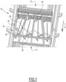
- Figure 1 shows a noise damper 10, according to an example of embodiment of the invention.
- the noise damper 10 is intended to equip an air conditioning system, in particular in a railway vehicle.
- the railway vehicle is for example an underground train.
- the air conditioning system is generally formed by an HVAC (Heat Ventilation Air Conditioning) unit arranged on a roof structure and one air duct system on the top of a ceiling. The air is blown from outlets placed on each side of the ceiling.
- HVAC Heating Ventilation Air Conditioning
- the main noise source inside the railway vehicle is fans of the HVAC unit.
- the critical point in term of noise level is the area just below diffuser closest to HVAC Unit.
- the noise damper 10 is arranged between an upstream duct 12 coming from the air conditioning system and a downstream duct 14 intended to distribute conditioned air towards a passenger area of the railway vehicle.
- the downstream duct 14 usually comprises outlets leading to the passenger area.
- This noise damper 10 is to reduce the noise coming from the fans of the HVAC unit.
- the noise damper 10 comprises a casing 16 comprising walls 18 delimiting an air passage extending in a longitudinal direction X between the upstream duct 12 and the downstream duct 14.
- the casing 16 is preferentially metallic, advantageously made of aluminum.
- the noise damper 10 has a length of about 1 meter in the longitudinal direction X.
- a longer noise damper (2 or 3m) would be better for the acoustic but not acceptable for the passenger in term of temperature comfort.
- the a somehowlic comfort would be better but it would be noisier for the passenger.
- a length of about 1 meter is optimal.
- Each wall 18 comprises at least one acoustic insulation layer, intended to absorb noise of the airflow circulating in contact of this acoustic insulation layer, in a manner known.
- the noise damper 10 also comprises at least one baffle 20 arranged in the air passage to separate the air passage in several channels. Each channel extends substantially parallel to the longitudinal direction X.
- the noise damper 10 comprises three baffles 20, separating the air passage into four channels.
- At least one of the baffles 20 is inclined in regard to the longitudinal direction X, so that the channels have not a constant cross section along the longitudinal direction X.
- the two central channels are narrow on the side of the upstream duct 12, and wide on the side of the downstream duct 14, whereas the lateral channels are wide on the side of the upstream duct 12, and narrow on the side of the downstream duct 14.
- each baffle 20 comprises an acoustic insulation layer 22 on its faces, so that each channel is transversally delimited between two acoustic insulation layers 22.
- Each acoustic insulation layer 22 preferentially has a thickness of 20 mm.
- Each channel also comprises acoustic insulation layers on its bottom wall and on its upper wall.
- the noise damping depends on the surface of acoustic insulation in contact with the air.
- the global surface of insulation in contact with the air is increased by adding baffles inside the noise damper, thus the baffles 20 allow reducing noise.
- baffles 20 improve the air guiding, avoiding turbulences.
- the noise damper 10 also comprises, in each channel, a helical deflector 24, extending substantially parallel to the longitudinal direction, i.e. in the direction of the airflow.
- Each helical deflector 24 has a helical surface extending around a central axis.
- the helical surface extends radially from the central axis to an inner surface of the acoustic insulation layers delimiting the channel. Consequently, the air necessarily flows between the helical surface and the acoustic insulation layers 22, along the helical surface.
- the airflow necessarily encounters the acoustic insulation layers 22 delimiting the channel, and the helical deflector blocks the direct acoustic waves coming from the upstream duct 12.
Landscapes
- Engineering & Computer Science (AREA)
- Mechanical Engineering (AREA)
- Chemical & Material Sciences (AREA)
- Combustion & Propulsion (AREA)
- General Engineering & Computer Science (AREA)
- Air-Conditioning For Vehicles (AREA)
- Soundproofing, Sound Blocking, And Sound Damping (AREA)
Abstract
- at least one baffle (20) arranged in the air passage to separate the air passage in several channels, each channel extending substantially parallel to a longitudinal direction (X) and
- a helical deflector (24) arranged in each channel, extending parallel to the longitudinal direction (X).
Description
- The present invention concerns a noise damper, in particular for an air conditioning system, preferentially in a railway vehicle.
- The main noise source equipment inside a railway vehicle passenger area is generally the air conditioning system HVAC (Heating Ventilation Air Conditioning Unit), and especially the fans which blow the air inside air ducts and towards the passenger area.
- A noise damper is already known from prior art. Such a noise damper is intended to equip the air conditioning system, and is arranged between a front air blower of the air conditioning system and the beginning of an air duct. The main function of the noise damper is to absorb the noise coming from the HVAC, and also to share the air in different directions.
- A known noise damper usually comprises a casing, for example made of aluminum, delimiting an air passage, the casing having walls each comprising an acoustic insulation layer. The acoustic insulation layers are for example made of several self-adhesive panels arranged on said walls of the casing.
- However, such a noise damper may be insufficient in the context of air conditioning systems comprising more and more powerful blowers.
- The invention aims proposing a more efficient noise damper.
- To this end, the invention relates to a noise damper, comprising a casing delimiting an air passage, the casing having walls each comprising an acoustic insulation layer, characterized in that the noise damper comprises:
- at least one baffle arranged in the air passage to separate the air passage in several channels, each channel extending substantially parallel to a longitudinal direction and
- a helical deflector arranged in each channel, extending parallel to the longitudinal direction.
- The baffles are intended to guide the air in order to avoid turbulences and to absorb the noise with more surface of insulation in contact with the air.
- Besides, the helical deflector gives acoustic advantage to make longer the circuit in the noise damper and create more reflection to the insulation. Besides, a helix does not slow the airflow, so a helix is a good compromise between aerodynamics and acoustics.
- A noise damper according to the invention may comprise any of the following features, taken alone or in any possible combination.
- The casing is metallic, preferentially made of aluminum.
- The noise damper has a length, in the longitudinal direction, substantially equal to 1 meter.
- At least one of the baffles is inclined in regard to the longitudinal direction, so that the channels have not a constant cross section along the longitudinal direction.
- Each baffle comprises an acoustic insulation layer on its faces.
- Each helical deflector has a helical surface extending around a central axis and extending radially from the central axis to an inner surface delimiting the corresponding channel.
- The invention relates to an air conditioning system, in particular for a railway vehicle, characterized in that it comprises a noise damper as disclosed above.
- The invention relates to a railway vehicle, in particular an underground train, characterized in that it comprises an air conditioning system as disclosed above.
- Several aspects and advantages of the invention will be enlightened in the following disclosure, given only as an example and made in reference to the attached figure, in which:
-
Figure 1 is an open view from above of a noise damper according to an example of embodiment of the invention. -
Figure 1 shows anoise damper 10, according to an example of embodiment of the invention. Thenoise damper 10 is intended to equip an air conditioning system, in particular in a railway vehicle. The railway vehicle is for example an underground train. - In an underground train, the air conditioning system is generally formed by an HVAC (Heat Ventilation Air Conditioning) unit arranged on a roof structure and one air duct system on the top of a ceiling. The air is blown from outlets placed on each side of the ceiling.
- The main noise source inside the railway vehicle is fans of the HVAC unit. The critical point in term of noise level is the area just below diffuser closest to HVAC Unit. Thus, the
noise damper 10 is arranged between anupstream duct 12 coming from the air conditioning system and adownstream duct 14 intended to distribute conditioned air towards a passenger area of the railway vehicle. Thedownstream duct 14 usually comprises outlets leading to the passenger area. - The function of this
noise damper 10 is to reduce the noise coming from the fans of the HVAC unit. - The
noise damper 10 comprises acasing 16 comprisingwalls 18 delimiting an air passage extending in a longitudinal direction X between theupstream duct 12 and thedownstream duct 14. Thecasing 16 is preferentially metallic, advantageously made of aluminum. - Preferentially, the
noise damper 10 has a length of about 1 meter in the longitudinal direction X. A longer noise damper (2 or 3m) would be better for the acoustic but not acceptable for the passenger in term of temperature comfort. On contrary, with a smaller noise damper or without any noise damper, the aeraulic comfort would be better but it would be noisier for the passenger. Thus, a length of about 1 meter is optimal. - Each
wall 18 comprises at least one acoustic insulation layer, intended to absorb noise of the airflow circulating in contact of this acoustic insulation layer, in a manner known. - The
noise damper 10 according to the invention also comprises at least onebaffle 20 arranged in the air passage to separate the air passage in several channels. Each channel extends substantially parallel to the longitudinal direction X. In the example shown, thenoise damper 10 comprises threebaffles 20, separating the air passage into four channels. - Preferentially, at least one of the
baffles 20 is inclined in regard to the longitudinal direction X, so that the channels have not a constant cross section along the longitudinal direction X. On the example shown, the two central channels are narrow on the side of theupstream duct 12, and wide on the side of thedownstream duct 14, whereas the lateral channels are wide on the side of theupstream duct 12, and narrow on the side of thedownstream duct 14. - Preferentially, each
baffle 20 comprises anacoustic insulation layer 22 on its faces, so that each channel is transversally delimited between twoacoustic insulation layers 22. - Each
acoustic insulation layer 22 preferentially has a thickness of 20 mm. - Each channel also comprises acoustic insulation layers on its bottom wall and on its upper wall.
- The noise damping depends on the surface of acoustic insulation in contact with the air. The global surface of insulation in contact with the air is increased by adding baffles inside the noise damper, thus the
baffles 20 allow reducing noise. - Besides, the
baffles 20 improve the air guiding, avoiding turbulences. - The
noise damper 10 also comprises, in each channel, ahelical deflector 24, extending substantially parallel to the longitudinal direction, i.e. in the direction of the airflow. - Each
helical deflector 24 has a helical surface extending around a central axis. The helical surface extends radially from the central axis to an inner surface of the acoustic insulation layers delimiting the channel. Consequently, the air necessarily flows between the helical surface and theacoustic insulation layers 22, along the helical surface. - In other words, because of the
helical deflector 24, the airflow necessarily encounters theacoustic insulation layers 22 delimiting the channel, and the helical deflector blocks the direct acoustic waves coming from theupstream duct 12.
Claims (8)
- A noise damper (10), comprising a casing (16) delimiting an air passage, the casing (16) having walls (18) each comprising an acoustic insulation layer, characterized in that the noise damper (10) comprises:- at least one baffle (20) arranged in the air passage to separate the air passage in several channels, each channel extending substantially parallel to a longitudinal direction (X) and- a helical deflector (24) arranged in each channel, extending parallel to the longitudinal direction (X).
- A noise damper (10) according to claim 1, wherein the casing (16) is metallic, preferentially made of aluminum.
- A noise damper (10) according to claim 1 or 2, having a length, in the longitudinal direction (X), substantially equal to 1 meter.
- A noise damper (10) according to any of preceding claims, wherein at least one of the baffles (20) is inclined in regard to the longitudinal direction (X), so that the channels have not a constant cross section along the longitudinal direction (X).
- A noise damper (10) according to any of preceding claims, wherein each baffle (20) comprises an acoustic insulation layer (22) on its faces.
- A noise damper (10) according to any of preceding claims, wherein each helical deflector (24) has a helical surface extending around a central axis and extending radially from the central axis to an inner surface delimiting the corresponding channel.
- An air conditioning system, in particular for a railway vehicle, characterized in that it comprises a noise damper (10) according to any of preceding claims.
- A railway vehicle, in particular an underground train, characterized in that it comprises an air conditioning system according to claim 7.
Priority Applications (3)
| Application Number | Priority Date | Filing Date | Title |
|---|---|---|---|
| EP23306390.8A EP4509381B1 (en) | 2023-08-18 | 2023-08-18 | Improved noise damper, in particular for an air conditioning system of a railway vehicle |
| ES23306390T ES3063392T3 (en) | 2023-08-18 | 2023-08-18 | Improved noise damper, in particular for an air conditioning system of a railway vehicle |
| US18/806,057 US20250060127A1 (en) | 2023-08-18 | 2024-08-15 | Noise damper, in particular for an air conditioning system of a railway vehicle |
Applications Claiming Priority (1)
| Application Number | Priority Date | Filing Date | Title |
|---|---|---|---|
| EP23306390.8A EP4509381B1 (en) | 2023-08-18 | 2023-08-18 | Improved noise damper, in particular for an air conditioning system of a railway vehicle |
Publications (3)
| Publication Number | Publication Date |
|---|---|
| EP4509381A1 true EP4509381A1 (en) | 2025-02-19 |
| EP4509381C0 EP4509381C0 (en) | 2026-01-28 |
| EP4509381B1 EP4509381B1 (en) | 2026-01-28 |
Family
ID=87889503
Family Applications (1)
| Application Number | Title | Priority Date | Filing Date |
|---|---|---|---|
| EP23306390.8A Active EP4509381B1 (en) | 2023-08-18 | 2023-08-18 | Improved noise damper, in particular for an air conditioning system of a railway vehicle |
Country Status (3)
| Country | Link |
|---|---|
| US (1) | US20250060127A1 (en) |
| EP (1) | EP4509381B1 (en) |
| ES (1) | ES3063392T3 (en) |
Citations (4)
| Publication number | Priority date | Publication date | Assignee | Title |
|---|---|---|---|---|
| US20060144638A1 (en) * | 2005-01-06 | 2006-07-06 | J. P. Environmental Products Inc. | Noise attenuator with laterally moving baffles |
| EP2426427A2 (en) * | 2010-09-03 | 2012-03-07 | EUR.EX S.r.l. | Helical silencer of the modular and assemblable type, in particular for ducts or channels for ventilation, air-conditioning or the like |
| CN104859674A (en) * | 2015-06-05 | 2015-08-26 | 南车青岛四方机车车辆股份有限公司 | Silencing air duct and railway vehicle |
| WO2016187291A1 (en) * | 2015-05-20 | 2016-11-24 | Rite-Hite Holding Corporation | Air duct silencer system |
Family Cites Families (7)
| Publication number | Priority date | Publication date | Assignee | Title |
|---|---|---|---|---|
| US3948349A (en) * | 1975-05-12 | 1976-04-06 | General Motors Corporation | Wave interference silencer |
| US4317502A (en) * | 1979-10-22 | 1982-03-02 | Harris Theodore R | Engine exhaust muffler |
| JPS59158308A (en) * | 1983-02-28 | 1984-09-07 | Hisao Kojima | Muffler |
| US4605092A (en) * | 1985-01-18 | 1986-08-12 | Harris Theodore R | Large, high r.p.m. diesel engine exhaust muffler |
| US20070221440A1 (en) * | 2006-03-24 | 2007-09-27 | Gilliland Don A | Air exhaust/inlet sound attenuation mechanism |
| KR100955413B1 (en) * | 2008-05-07 | 2010-05-04 | 이방수 | Air conditioner compressor |
| US8240427B2 (en) * | 2008-10-01 | 2012-08-14 | General Electric Company | Sound attenuation systems and methods |
-
2023
- 2023-08-18 ES ES23306390T patent/ES3063392T3/en active Active
- 2023-08-18 EP EP23306390.8A patent/EP4509381B1/en active Active
-
2024
- 2024-08-15 US US18/806,057 patent/US20250060127A1/en active Pending
Patent Citations (4)
| Publication number | Priority date | Publication date | Assignee | Title |
|---|---|---|---|---|
| US20060144638A1 (en) * | 2005-01-06 | 2006-07-06 | J. P. Environmental Products Inc. | Noise attenuator with laterally moving baffles |
| EP2426427A2 (en) * | 2010-09-03 | 2012-03-07 | EUR.EX S.r.l. | Helical silencer of the modular and assemblable type, in particular for ducts or channels for ventilation, air-conditioning or the like |
| WO2016187291A1 (en) * | 2015-05-20 | 2016-11-24 | Rite-Hite Holding Corporation | Air duct silencer system |
| CN104859674A (en) * | 2015-06-05 | 2015-08-26 | 南车青岛四方机车车辆股份有限公司 | Silencing air duct and railway vehicle |
Also Published As
| Publication number | Publication date |
|---|---|
| US20250060127A1 (en) | 2025-02-20 |
| EP4509381C0 (en) | 2026-01-28 |
| ES3063392T3 (en) | 2026-04-16 |
| EP4509381B1 (en) | 2026-01-28 |
Similar Documents
| Publication | Publication Date | Title |
|---|---|---|
| JP5643660B2 (en) | Railway vehicle | |
| US10864925B2 (en) | Power car for high-speed train | |
| JP6694329B2 (en) | Air conditioning duct for railway vehicles | |
| KR101745217B1 (en) | Cooling air interface in a blower housing | |
| KR101135044B1 (en) | Cool and hot air supply structure for driving room of railway vehicle | |
| CN104859674B (en) | A kind of noise elimination wind conduit and rail vehicle | |
| JP5163282B2 (en) | Defroster nozzle structure | |
| CN115973099B (en) | Concealed defrosting duct structure and automobile | |
| EP4509381B1 (en) | Improved noise damper, in particular for an air conditioning system of a railway vehicle | |
| KR101735047B1 (en) | An air venting apparatus for automobile | |
| CN104875764B (en) | A kind of noise elimination wind conduit and rail vehicle | |
| JP2009248866A (en) | Intake duct for vehicle air conditioning and air conditioner for vehicle | |
| US20070128997A1 (en) | Vehicle air duct structure | |
| JP2007331743A (en) | Air-blowing duct for defroster | |
| KR20110092371A (en) | Air Conditioning Duct Silencer for Railway Vehicles | |
| JP7427403B2 (en) | Defroster duct structure | |
| KR100533112B1 (en) | Air-conditioning duct silencer on the railway vehicles | |
| KR20150126592A (en) | Device for air-conditioning a vehicle comprising a defrosting pipe network | |
| JP3747816B2 (en) | Air conditioning duct for vehicles | |
| JP5474028B2 (en) | Air conditioning equipment and vehicles | |
| KR20130038564A (en) | Air venting apparatus for an automobile | |
| WO2011093052A1 (en) | Vehicular air conditioner unit | |
| CN109720366B (en) | Air-conditioning ducts for rail vehicles and rail vehicles | |
| KR20170000018A (en) | A railway vehicles for duct have the function even distribution | |
| JP4328232B2 (en) | Railway vehicle |
Legal Events
| Date | Code | Title | Description |
|---|---|---|---|
| PUAI | Public reference made under article 153(3) epc to a published international application that has entered the european phase |
Free format text: ORIGINAL CODE: 0009012 |
|
| STAA | Information on the status of an ep patent application or granted ep patent |
Free format text: STATUS: THE APPLICATION HAS BEEN PUBLISHED |
|
| STAA | Information on the status of an ep patent application or granted ep patent |
Free format text: STATUS: REQUEST FOR EXAMINATION WAS MADE |
|
| AK | Designated contracting states |
Kind code of ref document: A1 Designated state(s): AL AT BE BG CH CY CZ DE DK EE ES FI FR GB GR HR HU IE IS IT LI LT LU LV MC ME MK MT NL NO PL PT RO RS SE SI SK SM TR |
|
| 17P | Request for examination filed |
Effective date: 20250123 |
|
| GRAP | Despatch of communication of intention to grant a patent |
Free format text: ORIGINAL CODE: EPIDOSNIGR1 |
|
| RIC1 | Information provided on ipc code assigned before grant |
Ipc: F24F 13/08 20060101ALI20250311BHEP Ipc: F24F 13/02 20060101ALI20250311BHEP Ipc: F24F 13/24 20060101ALI20250311BHEP Ipc: B61D 27/00 20060101AFI20250311BHEP |
|
| STAA | Information on the status of an ep patent application or granted ep patent |
Free format text: STATUS: GRANT OF PATENT IS INTENDED |
|
| INTG | Intention to grant announced |
Effective date: 20250417 |
|
| GRAJ | Information related to disapproval of communication of intention to grant by the applicant or resumption of examination proceedings by the epo deleted |
Free format text: ORIGINAL CODE: EPIDOSDIGR1 |
|
| STAA | Information on the status of an ep patent application or granted ep patent |
Free format text: STATUS: REQUEST FOR EXAMINATION WAS MADE |
|
| INTC | Intention to grant announced (deleted) | ||
| GRAP | Despatch of communication of intention to grant a patent |
Free format text: ORIGINAL CODE: EPIDOSNIGR1 |
|
| STAA | Information on the status of an ep patent application or granted ep patent |
Free format text: STATUS: GRANT OF PATENT IS INTENDED |
|
| INTG | Intention to grant announced |
Effective date: 20251017 |
|
| GRAS | Grant fee paid |
Free format text: ORIGINAL CODE: EPIDOSNIGR3 |
|
| GRAA | (expected) grant |
Free format text: ORIGINAL CODE: 0009210 |
|
| STAA | Information on the status of an ep patent application or granted ep patent |
Free format text: STATUS: THE PATENT HAS BEEN GRANTED |
|
| AK | Designated contracting states |
Kind code of ref document: B1 Designated state(s): AL AT BE BG CH CY CZ DE DK EE ES FI FR GB GR HR HU IE IS IT LI LT LU LV MC ME MK MT NL NO PL PT RO RS SE SI SK SM TR |
|
| REG | Reference to a national code |
Ref country code: CH Ref legal event code: F10 Free format text: ST27 STATUS EVENT CODE: U-0-0-F10-F00 (AS PROVIDED BY THE NATIONAL OFFICE) Effective date: 20260128 Ref country code: GB Ref legal event code: FG4D |
|
| REG | Reference to a national code |
Ref country code: CH Ref legal event code: R17 Free format text: ST27 STATUS EVENT CODE: U-0-0-R10-R17 (AS PROVIDED BY THE NATIONAL OFFICE) Effective date: 20260205 |
|
| REG | Reference to a national code |
Ref country code: DE Ref legal event code: R096 Ref document number: 602023011293 Country of ref document: DE |
|
| REG | Reference to a national code |
Ref country code: IE Ref legal event code: FG4D |
|
| U01 | Request for unitary effect filed |
Effective date: 20260216 |
|
| U07 | Unitary effect registered |
Designated state(s): AT BE BG DE DK EE FI FR IT LT LU LV MT NL PT RO SE SI Effective date: 20260220 |
|
| REG | Reference to a national code |
Ref country code: ES Ref legal event code: FG2A Ref document number: 3063392 Country of ref document: ES Kind code of ref document: T3 Effective date: 20260416 |
|
| PG25 | Lapsed in a contracting state [announced via postgrant information from national office to epo] |
Ref country code: RS Free format text: LAPSE BECAUSE OF FAILURE TO SUBMIT A TRANSLATION OF THE DESCRIPTION OR TO PAY THE FEE WITHIN THE PRESCRIBED TIME-LIMIT Effective date: 20260428 |
|
| PG25 | Lapsed in a contracting state [announced via postgrant information from national office to epo] |
Ref country code: PL Free format text: LAPSE BECAUSE OF FAILURE TO SUBMIT A TRANSLATION OF THE DESCRIPTION OR TO PAY THE FEE WITHIN THE PRESCRIBED TIME-LIMIT Effective date: 20260128 |
|
| PG25 | Lapsed in a contracting state [announced via postgrant information from national office to epo] |
Ref country code: GR Free format text: LAPSE BECAUSE OF FAILURE TO SUBMIT A TRANSLATION OF THE DESCRIPTION OR TO PAY THE FEE WITHIN THE PRESCRIBED TIME-LIMIT Effective date: 20260429 |
|
| PG25 | Lapsed in a contracting state [announced via postgrant information from national office to epo] |
Ref country code: NO Free format text: LAPSE BECAUSE OF FAILURE TO SUBMIT A TRANSLATION OF THE DESCRIPTION OR TO PAY THE FEE WITHIN THE PRESCRIBED TIME-LIMIT Effective date: 20260428 |
|
| PG25 | Lapsed in a contracting state [announced via postgrant information from national office to epo] |
Ref country code: HR Free format text: LAPSE BECAUSE OF FAILURE TO SUBMIT A TRANSLATION OF THE DESCRIPTION OR TO PAY THE FEE WITHIN THE PRESCRIBED TIME-LIMIT Effective date: 20260128 |
|
| PG25 | Lapsed in a contracting state [announced via postgrant information from national office to epo] |
Ref country code: IS Free format text: LAPSE BECAUSE OF FAILURE TO SUBMIT A TRANSLATION OF THE DESCRIPTION OR TO PAY THE FEE WITHIN THE PRESCRIBED TIME-LIMIT Effective date: 20260528 |