EP4509368A1 - Electrical component support structure - Google Patents
Electrical component support structure Download PDFInfo
- Publication number
- EP4509368A1 EP4509368A1 EP24187729.9A EP24187729A EP4509368A1 EP 4509368 A1 EP4509368 A1 EP 4509368A1 EP 24187729 A EP24187729 A EP 24187729A EP 4509368 A1 EP4509368 A1 EP 4509368A1
- Authority
- EP
- European Patent Office
- Prior art keywords
- electrical component
- end portion
- vehicle
- bracket
- internal combustion
- Prior art date
- Legal status (The legal status is an assumption and is not a legal conclusion. Google has not performed a legal analysis and makes no representation as to the accuracy of the status listed.)
- Pending
Links
Images




Classifications
-
- B—PERFORMING OPERATIONS; TRANSPORTING
- B60—VEHICLES IN GENERAL
- B60R—VEHICLES, VEHICLE FITTINGS, OR VEHICLE PARTS, NOT OTHERWISE PROVIDED FOR
- B60R16/00—Electric or fluid circuits specially adapted for vehicles and not otherwise provided for; Arrangement of elements of electric or fluid circuits specially adapted for vehicles and not otherwise provided for
- B60R16/02—Electric or fluid circuits specially adapted for vehicles and not otherwise provided for; Arrangement of elements of electric or fluid circuits specially adapted for vehicles and not otherwise provided for electric constitutive elements
- B60R16/0207—Wire harnesses
- B60R16/0215—Protecting, fastening and routing means therefor
-
- B—PERFORMING OPERATIONS; TRANSPORTING
- B60—VEHICLES IN GENERAL
- B60K—ARRANGEMENT OR MOUNTING OF PROPULSION UNITS OR OF TRANSMISSIONS IN VEHICLES; ARRANGEMENT OR MOUNTING OF PLURAL DIVERSE PRIME-MOVERS IN VEHICLES; AUXILIARY DRIVES FOR VEHICLES; INSTRUMENTATION OR DASHBOARDS FOR VEHICLES; ARRANGEMENTS IN CONNECTION WITH COOLING, AIR INTAKE, GAS EXHAUST OR FUEL SUPPLY OF PROPULSION UNITS IN VEHICLES
- B60K6/00—Arrangement or mounting of plural diverse prime-movers for mutual or common propulsion, e.g. hybrid propulsion systems comprising electric motors and internal combustion engines
- B60K6/20—Arrangement or mounting of plural diverse prime-movers for mutual or common propulsion, e.g. hybrid propulsion systems comprising electric motors and internal combustion engines the prime-movers consisting of electric motors and internal combustion engines, e.g. HEVs
- B60K6/22—Arrangement or mounting of plural diverse prime-movers for mutual or common propulsion, e.g. hybrid propulsion systems comprising electric motors and internal combustion engines the prime-movers consisting of electric motors and internal combustion engines, e.g. HEVs characterised by apparatus, components or means specially adapted for HEVs
- B60K6/40—Arrangement or mounting of plural diverse prime-movers for mutual or common propulsion, e.g. hybrid propulsion systems comprising electric motors and internal combustion engines the prime-movers consisting of electric motors and internal combustion engines, e.g. HEVs characterised by apparatus, components or means specially adapted for HEVs characterised by the assembly or relative disposition of components
Definitions
- This invention relates to an electrical component support structure.
- Patent Literature 1 In an electric vehicle, member that protects a power cable in the event of a collision of the vehicle is known (refer to Patent Literature 1).
- an inverter is fixed to an upper portion of a drivetrain by a front bracket, a protector is integrally provided with the front bracket, and the power cable extends from a side surface of the inverter in a lateral direction.
- the protector is disposed in front of the power cable, and the protector protects the power cable from a device moving rearward toward the inverter in the event of a collision of the vehicle.
- the protector is located at a lower portion of the inverter, the protector is not suitable for protecting components disposed at an upper portion of the inverter.
- An electrical component such as an inverter includes a cable connection portion of which an upper surface portion is connected to a high-voltage cable, and the cable connection portion is covered with a cover member.
- a cover member needs to be protected from an obstacle in the event of a collision of the vehicle.
- This invention has been made in view of the above-described problems, and an object of this invention is to provide an electrical component support structure capable of suppressing vibration of an electrical component disposed above a drive device, and protecting a cover member of the electrical component in the event of a frontal collision of a vehicle.
- an electrical component support structure for an electrical component mounted in a vehicle including an internal combustion engine, a drive device connected to the internal combustion engine, and a motor provided on the drive device, and fixed to an upper portion of the drive device by a lower bracket.
- a cable connection portion connected to a high-voltage cable supplying electric power to the motor and a cover member covering the cable connection portion are provided at an upper end portion of the electrical component.
- the electrical component is fixed to the internal combustion engine by an upper bracket connected to the upper end portion of the electrical component.
- the upper bracket covers an upper portion of the cover member.
- An electrical component support structure is an electrical component support structure for an electrical component mounted in a vehicle including an internal combustion engine, a drive device connected to the internal combustion engine, and a motor provided on the drive device, and fixed to an upper portion of the drive device by a lower bracket.
- a cable connection portion connected to a high-voltage cable supplying electric power to the motor and a cover member covering the cable connection portion are provided at an upper end portion of the electrical component.
- the electrical component is fixed to the internal combustion engine by an upper bracket connected to the upper end portion of the electrical component.
- the upper bracket covers an upper portion of the cover member.
- the electrical component support structure can suppress vibration of the electrical component disposed above the drive device, and protect the cover member of the electrical component in the event of a frontal collision of the vehicle.
- Figs. 1 to 6 are views showing the electrical component support structure of embodiments according to this invention.
- the up and down, front and rear, and left and right directions are defined such that with reference to an engine and a transmission installed in a vehicle, a front and rear direction of the vehicle is the front and rear direction, a side where an upper member is disposed is the front, and a side where a dash panel is disposed is the rear.
- a left and right direction of the vehicle is the left and right direction, a transmission side is the left, and an engine side is the right.
- a height direction of the engine and the transmission is the up and down direction, an electrical component side is the top or up, and a side opposite to an electrical component is the bottom or down.
- an engine compartment 2 is disposed at a front portion of a vehicle 1, and the engine compartment 2 is surrounded by an upper member 3A, a dash panel 3B located behind the upper member 3A, a left side member 3C extending rearward from a left end portion of the upper member 3A, and a right side member 3D extending rearward from a right end portion of the upper member 3A.
- An engine 4 as an internal combustion engine and a transmission 5 as a drive device are disposed in the engine compartment 2, and the transmission 5 is connected to the engine 4.
- the engine 4 includes a cylinder block 4A; a cylinder head 4B attached to an upper portion of the cylinder block 4A; and a cylinder head cover 4C attached to an upper portion of the cylinder head 4B, and the transmission 5 includes a transmission case 5A.
- the transmission case 5A is connected to the cylinder block 4A.
- the engine 4 and the transmission 5 are installed side by side in a width direction of the vehicle 1 (hereinafter, referred to as the vehicle width direction), and the transmission 5 is installed below the cylinder head 4B.
- a transmission mechanism, a differential device, and the like formed of transmission gears and the like (not shown) are installed inside the transmission case 5A.
- the transmission 5 changes the speed of power (rotation), which is transmitted from a crankshaft (not shown) of the engine 4, using the transmission mechanism, and transmits the power to left and right front wheels (not shown) via left and right drive shafts (not shown) using the differential device.
- a motor-generator 6 as a motor is attached to the transmission case 5A (refer to Fig. 1 ).
- the motor-generator 6 transmits power to the transmission mechanism of the transmission 5 via a speed reduction mechanism (not shown), and performs motor traveling using the motor-generator 6 as a drive source and hybrid traveling using both the engine 4 and the motor-generator 6.
- an intake manifold 7 is connected to a rear surface of the cylinder head 4B.
- the intake manifold 7 introduces intake air from intake ports (not shown) formed in the cylinder head 4B to cylinders (not shown) formed in the cylinder block 4A.
- a catalytic converter 8 is connected to a front surface of the cylinder head 4B. Exhaust gas is discharged from the cylinders to the catalytic converter 8 via exhaust ports (not shown) of the cylinder head 4B and an exhaust manifold.
- an auxiliary device 11 such as a coolant case is connected to a left side wall 4a of the cylinder head 4B, and the auxiliary device 11 is connected to a radiator (not shown) via coolant pipes 11A and 11B (refer to Fig. 1 ).
- an inverter 9 as an electrical component is disposed at an upper portion of the transmission case 5A.
- the inverter 9 converts DC electric power supplied from a high-voltage battery (not shown) into three-phase AC electric power to supply the three-phase AC electric power to the motor-generator 6, and converts three-phase AC electric power generated by the motor-generator 6 into DC electric power to charge the high-voltage battery with the DC electric power.
- a low-voltage battery 20 is disposed on the left side of the inverter 9.
- the inverter 9 is disposed directly above the transmission case 5A such that a longitudinal direction of the inverter 9 is aligned with the front and rear direction of the vehicle 1 and a lateral direction of the inverter 9 is aligned with the vehicle width direction.
- the inverter 9 is formed to be long in the front and rear direction and shorter in the vehicle width direction than in the front and rear direction, and is formed in a rectangular parallelepiped shape.
- a lower bracket 10 is provided on a lower wall 9A of the inverter 9.
- the lower bracket 10 includes a horizontal bracket portion 10A and a vertical bracket portion 10B.
- the horizontal bracket portion 10A extends in the front and rear direction along the lower wall 9A of the inverter 9, and the inverter 9 is fixed to the horizontal bracket portion 10A by fastening bolts (not shown) to the lower wall 9A from below the horizontal bracket portion 10A.
- a rear end portion and a central portion of a left end portion of the horizontal bracket portion 10A in the front and rear direction are fastened to the transmission case 5A by bolts 30A (refer to Figs. 2 and 5 ), and a front end portion of the horizontal bracket portion 10A is fastened to an upper end portion of the vertical bracket portion 10B by bolts 30B.
- a lower end portion of the vertical bracket portion 10B is fastened to the transmission case 5A by bolts 30C.
- the inverter 9 is attached to the transmission case 5A by the lower bracket 10.
- the high-voltage cable 12 includes a protective protector 12A that is deformable; a protective case 12B connected to the protective protector 12A; and a U-phase cable 12a, a V-phase cable 12b, and a W-phase cable 12c built into the protective protector 12A and the protective case 12B ( Fig. 5 shows parts of the cables 12a, 12b, and 12c).
- One end portions of the U-phase cable 12a, the V-phase cable 12b, and the W-phase cable 12c are connected to the motor-generator 6, and the other end portions of the U-phase cable 12a, the V-phase cable 12b, and the W-phase cable 12c are connected to cable connection portions 9a, 9b, and 9c provided on an upper wall 9B of the inverter 9.
- the upper wall 9B of the inverter 9 forms an upper end portion of the inverter 9.
- a cover member 21 is provided at the upper end portion of the inverter 9, and the cover member 21 is fastened to a front end and a rear end of the upper end portion of the inverter 9 by bolts 30D. Accordingly, the cable connection portions 9a, 9b, and 9c and connection portions of the U-phase cable 12a, the V-phase cable 12b, and the W-phase cable 12c connected to the cable connection portions 9a, 9b, and 9c are covered from above by the cover member 21, and are protected by the cover member 21.
- an upper bracket 22 is attached to the upper end portion of the inverter 9, and the upper bracket 22 covers an upper portion of the cover member 21.
- the upper bracket 22 includes a bracket body portion 23 and an engine-side attachment portion 24.
- the bracket body portion 23 extends in the front and rear direction along the upper wall 9B of the inverter 9 (refer to Fig. 6 ), and a length of the bracket body portion 23 in the front and rear direction is formed to be longer than a length of the cover member 21 in the front and rear direction.
- a dimension of a front end portion of the bracket body portion 23 in the vehicle width direction is formed to be larger than a dimension of the cover member 21 in the vehicle width direction, and the front end portion and a rear end portion of the bracket body portion 23 are fastened to the upper wall 9B of the inverter 9 by bolts 30E and 30F.
- a pair of bolt fastening portions 9C are provided at a front end portion of the upper wall 9B of the inverter 9, and the bolt fastening portions 9C protrude upward from the upper wall 9B of the inverter 9.
- the front end portion of the bracket body portion 23 is fastened to the bolt fastening portions 9C by the bolts 30E.
- bolt fastening portions 9D are provided at the rear end portion of the upper wall 9B of the inverter 9, and the bolt fastening portions 9D protrude upward from the upper wall 9B of the inverter 9.
- the rear end portion of the bracket body portion 23 is fastened to the bolt fastening portions 9D by the bolts 30F.
- the engine-side attachment portion 24 protrudes from a right end portion 23a of the bracket body portion 23 toward an engine 4 side on the right, and the right end portion is fastened to an upper end portion of an EGR passage portion 4c, which is provided at a left end portion of the cylinder head cover 4C, by bolts 30G.
- an engine-side bracket 25 is provided at an upper portion of the EGR passage portion 4c of the cylinder head cover 4C, and a right end portion of the engine-side attachment portion 24 is fastened to an upper end portion of the engine-side bracket 25 by the bolts 30G.
- the upper wall 9B of the inverter 9 is fixed to the engine 4 by the upper bracket 22.
- the engine-side attachment portion 24 of this embodiment forms an internal combustion engine-side attachment portion, and the bolts 30E, 30F, and 30G form fasteners.
- an inclined surface 23A is formed at a front end portion of the bracket body portion 23 of the upper bracket 22, and the inclined surface 23A is inclined toward the upper side as the inclined surface 23A extends rearward from the front end portion.
- an inclined portion 23D is formed in the bracket body portion 23.
- the inclined portion 23D is inclined downward from the right end portion 23a of the bracket body portion 23 toward an inclination end portion 23b on the left, and extends in the front and rear direction.
- the upper bracket 22 since the upper bracket 22 includes the inclined portion 23D extending in the front and rear direction, the torsional rigidity of the bracket body portion 23 with respect to the engine-side attachment portion 24 as the center is increased.
- the right end portion 23a of the bracket body portion 23 corresponds to an inclination start portion.
- recesses 23B and 23C are formed in the front end portion of the bracket body portion 23, and the recesses 23B and 23C are formed by depressing the inclined surface 23A downward such that the recesses 23B and 23C are located below the inclined surface 23A.
- the inclined surface 23A includes a left-side side wall 23e of the recess 23B and a right side wall portion 23f of the recess 23C, and the left-side side wall 23e and the right side wall portion 23f are inclined parallel to the inclined surface 23A. Namely, the left-side side wall 23e and the right side wall portion 23f are parts of the inclined surface 23A.
- Heads 30e of the bolts 30E are disposed in the recesses 23B and 23C. Namely, threaded portions (not shown) of the bolts 30E penetrate through bottom portions of the recesses 23B and 23C, and are fastened to the upper wall 9B of the inverter 9.
- the heads 30e of the bolts 30E are disposed in the recesses 23B and 23C, and as a result, upper ends 30u of the heads 30e are disposed in the recesses 23B and 23C.
- the protective case 12B located on the side of the cable connection portions 9a, 9b, and 9c of the high-voltage cable 12 is disposed below the engine-side attachment portion 24.
- the inverter 9 of this embodiment is mounted in the vehicle 1 including the engine 4; the transmission 5 connected to the engine 4; and the motor-generator 6 provided on the transmission 5, and is fixed to the upper portion of the transmission 5 by the lower bracket 10.
- the upper wall 9B of the inverter 9 is provided with the cable connection portions 9a, 9b, and 9c connected to the high-voltage cable 12 that supplies electric power to the motor-generator 6, and the cover member 21 that covers the cable connection portions 9a, 9b, and 9c.
- the inverter 9 is fixed to the engine 4 by the upper bracket 22 connected to the upper wall 9B of the inverter 9, and the upper bracket 22 covers an upper portion of the cover member 21.
- the upper bracket 22 has a shape that covers the upper portion of the cover member 21, an obstacle 41 moving from the front of the vehicle 1 toward a cover member 21 side in the event of a frontal collision of the vehicle 1 is moved upward by the upper bracket 22. Therefore, the obstacle 41 can be prevented from colliding with the cover member 21 (refer to Fig. 6 ).
- the upper bracket 22 of this embodiment includes the inclined portion 23D extending in the front and rear direction, the rigidity of the upper bracket 22 in the front and rear direction is increased. Accordingly, when an impact is applied to the upper bracket 22 from the front, it is made difficult for the upper bracket 22 to deform. Therefore, the impact can be effectively prevented from being applied to the cover member 21.
- the gap can be used as a cushioning material, and the cover member 21 can be protected by the upper bracket 22.
- the dimension of the front end portion of the upper bracket 22 in the vehicle width direction is formed to be larger than the dimension of the cover member 21 in the vehicle width direction.
- the front of the cover member 21 can be covered over a wide range of the front end portion of the upper bracket 22 in the vehicle width direction. For this reason, the obstacle 41 moving from the front of the vehicle 1 toward the cover member 21 side in the event of a frontal collision of the vehicle 1 can be more reliably prevented from colliding with the cover member 21.
- the inclined surface 23A is formed at the front end portion of the upper bracket 22, and the inclined surface 23A is inclined toward the upper side as the inclined surface 23A extends rearward from the front end portion.
- the obstacle 41 moving from the front of the vehicle 1 toward the cover member 21 side is bounced upward by the inclined surface 23A disposed at the front end portion of the upper bracket 22 (refer to Fig. 6 ). Therefore, the obstacle 41 can be kept away from the cover member 21. For this reason, the obstacle 41 can be more reliably prevented from colliding with the cover member 21.
- the front end portion of the upper bracket 22 includes the recesses 23B and 23C formed by depressing the inclined surface 23A downward such that the recesses 23B and 23C are located below the inclined surface 23A.
- the front end portion of the upper bracket 22 is fastened to the upper wall 9B of the inverter 9 by the bolts 30E, and the upper ends 30u of the bolts 30E are disposed in the recesses 23B and 23C.
- the upper ends 30u of the bolts 30E can be located below the inclined surface 23A, and the obstacle 41 can be guided upward along the inclined surface 23A while being prevented from colliding with the heads 30e of the bolts 30E.
- the obstacle 41 can be more reliably prevented from colliding with the cover member 21.
- the upper bracket 22 includes the bracket body portion 23 of which the front end portion and the rear end portion are fastened to the upper wall 9B of the inverter 9 by the bolts 30B and 30C, and the engine-side attachment portion 24 protruding from the bracket body portion 23 toward the engine 4 side, and fastened to the upper end portion of the EGR passage portion 4c of the cylinder head cover 4C by the bolts 30G.
- the side of the cable connection portions 9a, 9b, and 9c of the high-voltage cable 12 is disposed below the engine-side attachment portion 24.
- the obstacle 41 can be caused to collide with the engine-side attachment portion 24 protruding from the bracket body portion 23 toward the engine 4 side, and in the event of a frontal collision_of the vehicle 1, the high-voltage cable 12 can be protected from collision with the obstacle 41.
Landscapes
- Engineering & Computer Science (AREA)
- Mechanical Engineering (AREA)
- Chemical & Material Sciences (AREA)
- Combustion & Propulsion (AREA)
- Transportation (AREA)
- Arrangement Or Mounting Of Propulsion Units For Vehicles (AREA)
- Hybrid Electric Vehicles (AREA)
Abstract
To provide an electrical component support structure capable of suppressing vibration of an electrical component disposed above a drive device, and protecting a cover member of the electrical component in the event of a frontal collision of a vehicle.
[Solution]
In a support structure of an inverter 9, an upper wall 9B of the inverter 9 is provided with a cable connection portion connected to a high-voltage cable 12 supplying electric power to a motor-generator 6, and a cover member 21 covering the cable connection portion. The inverter 9 is fixed to an engine by an upper bracket 22 connected to the upper wall 9B of the inverter 9, and the upper bracket 22 covers an upper portion of the cover member 21.
Description
- This invention relates to an electrical component support structure.
- In an electric vehicle, member that protects a power cable in the event of a collision of the vehicle is known (refer to Patent Literature 1).
- In the electric vehicle described in Patent Literature 1, an inverter is fixed to an upper portion of a drivetrain by a front bracket, a protector is integrally provided with the front bracket, and the power cable extends from a side surface of the inverter in a lateral direction.
- The protector is disposed in front of the power cable, and the protector protects the power cable from a device moving rearward toward the inverter in the event of a collision of the vehicle.
- [Patent Literature 1]
JP 2013-233836 A - However, in a conventional electric vehicle, since the protector is located at a lower portion of the inverter, the protector is not suitable for protecting components disposed at an upper portion of the inverter.
- An electrical component such as an inverter includes a cable connection portion of which an upper surface portion is connected to a high-voltage cable, and the cable connection portion is covered with a cover member. In such an electrical component, a cover member needs to be protected from an obstacle in the event of a collision of the vehicle.
- In addition, when a lower portion of the electrical component is attached to a drive device such as a drivetrain by a bracket, vibration of an upper portion of the electrical component may increase, which is a risk. Therefore, it is necessary to suppress vibration of the electrical component disposed above the drive device, and protect the cover member in the event of a frontal collision of the vehicle.
- This invention has been made in view of the above-described problems, and an object of this invention is to provide an electrical component support structure capable of suppressing vibration of an electrical component disposed above a drive device, and protecting a cover member of the electrical component in the event of a frontal collision of a vehicle.
- According to aspects of this invention, there is provided an electrical component support structure for an electrical component mounted in a vehicle including an internal combustion engine, a drive device connected to the internal combustion engine, and a motor provided on the drive device, and fixed to an upper portion of the drive device by a lower bracket. A cable connection portion connected to a high-voltage cable supplying electric power to the motor and a cover member covering the cable connection portion are provided at an upper end portion of the electrical component. The electrical component is fixed to the internal combustion engine by an upper bracket connected to the upper end portion of the electrical component. The upper bracket covers an upper portion of the cover member.
- According to this invention described above, it is possible to suppress vibration of the electrical component disposed above the drive device, and it is possible to protect the cover member of the electrical component in the event of a frontal collision of the vehicle.
-
- [
Fig. 1] Fig. 1 is a plan view of an engine compartment of a vehicle having an electrical component support structure according to an embodiment of this invention. - [
Fig. 2] Fig. 2 is a plan view of the electrical component support structure according to an embodiment of this invention. - [
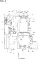
Fig. 3] Fig. 3 is a front view of the electrical component support structure according to an embodiment of this invention. - [
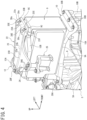
Fig. 4] Fig. 4 is a perspective view of the electrical component support structure according to an embodiment of this invention. - [
Fig. 5] Fig. 5 is a top view of an electrical component from which an upper bracket is removed, as a figure showing the electrical component support structure according to an embodiment of this invention. - [
Fig. 6] Fig. 6 is a left side view of the electrical component support structure according to an embodiment of this invention, as a figure showing a state of movement of an obstacle. - An electrical component support structure according to embodiments of this invention is an electrical component support structure for an electrical component mounted in a vehicle including an internal combustion engine, a drive device connected to the internal combustion engine, and a motor provided on the drive device, and fixed to an upper portion of the drive device by a lower bracket. A cable connection portion connected to a high-voltage cable supplying electric power to the motor and a cover member covering the cable connection portion are provided at an upper end portion of the electrical component. The electrical component is fixed to the internal combustion engine by an upper bracket connected to the upper end portion of the electrical component. The upper bracket covers an upper portion of the cover member.
- Accordingly, the electrical component support structure according to embodiments of this invention can suppress vibration of the electrical component disposed above the drive device, and protect the cover member of the electrical component in the event of a frontal collision of the vehicle.
- Hereinafter, embodiments of an electrical component support structure according to this invention will be described with reference to the drawings.
-
Figs. 1 to 6 are views showing the electrical component support structure of embodiments according to this invention. - In
Figs. 1 to 6 , the up and down, front and rear, and left and right directions are defined such that with reference to an engine and a transmission installed in a vehicle, a front and rear direction of the vehicle is the front and rear direction, a side where an upper member is disposed is the front, and a side where a dash panel is disposed is the rear. - A left and right direction of the vehicle (vehicle width direction) is the left and right direction, a transmission side is the left, and an engine side is the right.
- A height direction of the engine and the transmission is the up and down direction, an electrical component side is the top or up, and a side opposite to an electrical component is the bottom or down.
- First, a configuration will be described.
- In
Fig. 1 , anengine compartment 2 is disposed at a front portion of a vehicle 1, and theengine compartment 2 is surrounded by anupper member 3A, adash panel 3B located behind theupper member 3A, a left side member 3C extending rearward from a left end portion of theupper member 3A, and aright side member 3D extending rearward from a right end portion of theupper member 3A. - An
engine 4 as an internal combustion engine and atransmission 5 as a drive device are disposed in theengine compartment 2, and thetransmission 5 is connected to theengine 4. - As shown in
Figs. 1 and3 , theengine 4 includes acylinder block 4A; acylinder head 4B attached to an upper portion of thecylinder block 4A; and acylinder head cover 4C attached to an upper portion of thecylinder head 4B, and thetransmission 5 includes atransmission case 5A. - The
transmission case 5A is connected to thecylinder block 4A. Theengine 4 and thetransmission 5 are installed side by side in a width direction of the vehicle 1 (hereinafter, referred to as the vehicle width direction), and thetransmission 5 is installed below thecylinder head 4B. - A transmission mechanism, a differential device, and the like formed of transmission gears and the like (not shown) are installed inside the
transmission case 5A. Thetransmission 5 changes the speed of power (rotation), which is transmitted from a crankshaft (not shown) of theengine 4, using the transmission mechanism, and transmits the power to left and right front wheels (not shown) via left and right drive shafts (not shown) using the differential device. - A motor-
generator 6 as a motor is attached to thetransmission case 5A (refer toFig. 1 ). The motor-generator 6 transmits power to the transmission mechanism of thetransmission 5 via a speed reduction mechanism (not shown), and performs motor traveling using the motor-generator 6 as a drive source and hybrid traveling using both theengine 4 and the motor-generator 6. - As shown in
Fig. 1 , an intake manifold 7 is connected to a rear surface of thecylinder head 4B. The intake manifold 7 introduces intake air from intake ports (not shown) formed in thecylinder head 4B to cylinders (not shown) formed in thecylinder block 4A. - A
catalytic converter 8 is connected to a front surface of thecylinder head 4B. Exhaust gas is discharged from the cylinders to thecatalytic converter 8 via exhaust ports (not shown) of thecylinder head 4B and an exhaust manifold. - As shown in
Fig. 3 , anauxiliary device 11 such as a coolant case is connected to aleft side wall 4a of thecylinder head 4B, and theauxiliary device 11 is connected to a radiator (not shown) viacoolant pipes Fig. 1 ). - As shown in
Figs. 3 and4 , aninverter 9 as an electrical component is disposed at an upper portion of thetransmission case 5A. Theinverter 9 converts DC electric power supplied from a high-voltage battery (not shown) into three-phase AC electric power to supply the three-phase AC electric power to the motor-generator 6, and converts three-phase AC electric power generated by the motor-generator 6 into DC electric power to charge the high-voltage battery with the DC electric power. A low-voltage battery 20 is disposed on the left side of theinverter 9. - As shown in
Fig. 4 , theinverter 9 is disposed directly above thetransmission case 5A such that a longitudinal direction of theinverter 9 is aligned with the front and rear direction of the vehicle 1 and a lateral direction of theinverter 9 is aligned with the vehicle width direction. Namely, theinverter 9 is formed to be long in the front and rear direction and shorter in the vehicle width direction than in the front and rear direction, and is formed in a rectangular parallelepiped shape. - A
lower bracket 10 is provided on alower wall 9A of theinverter 9. Thelower bracket 10 includes ahorizontal bracket portion 10A and avertical bracket portion 10B. - The
horizontal bracket portion 10A extends in the front and rear direction along thelower wall 9A of theinverter 9, and theinverter 9 is fixed to thehorizontal bracket portion 10A by fastening bolts (not shown) to thelower wall 9A from below thehorizontal bracket portion 10A. - A rear end portion and a central portion of a left end portion of the
horizontal bracket portion 10A in the front and rear direction are fastened to thetransmission case 5A bybolts 30A (refer toFigs. 2 and5 ), and a front end portion of thehorizontal bracket portion 10A is fastened to an upper end portion of thevertical bracket portion 10B bybolts 30B. - As shown in
Figs. 3 and6 , a lower end portion of thevertical bracket portion 10B is fastened to thetransmission case 5A bybolts 30C. In such a manner, theinverter 9 is attached to thetransmission case 5A by thelower bracket 10. - As shown in
Fig. 5 , the motor-generator 6 and theinverter 9 are connected by a high-voltage cable 12. The high-voltage cable 12 includes aprotective protector 12A that is deformable; aprotective case 12B connected to theprotective protector 12A; and aU-phase cable 12a, a V-phase cable 12b, and a W-phase cable 12c built into theprotective protector 12A and theprotective case 12B (Fig. 5 shows parts of thecables - One end portions of the
U-phase cable 12a, the V-phase cable 12b, and the W-phase cable 12c are connected to the motor-generator 6, and the other end portions of theU-phase cable 12a, the V-phase cable 12b, and the W-phase cable 12c are connected tocable connection portions upper wall 9B of theinverter 9. Theupper wall 9B of theinverter 9 forms an upper end portion of theinverter 9. - A
cover member 21 is provided at the upper end portion of theinverter 9, and thecover member 21 is fastened to a front end and a rear end of the upper end portion of theinverter 9 bybolts 30D. Accordingly, thecable connection portions U-phase cable 12a, the V-phase cable 12b, and the W-phase cable 12c connected to thecable connection portions cover member 21, and are protected by thecover member 21. - As shown in
Figs. 3 and4 , anupper bracket 22 is attached to the upper end portion of theinverter 9, and theupper bracket 22 covers an upper portion of thecover member 21. - The
upper bracket 22 includes abracket body portion 23 and an engine-side attachment portion 24. - The
bracket body portion 23 extends in the front and rear direction along theupper wall 9B of the inverter 9 (refer toFig. 6 ), and a length of thebracket body portion 23 in the front and rear direction is formed to be longer than a length of thecover member 21 in the front and rear direction. - As shown in
Fig. 2 , a dimension of a front end portion of thebracket body portion 23 in the vehicle width direction is formed to be larger than a dimension of thecover member 21 in the vehicle width direction, and the front end portion and a rear end portion of thebracket body portion 23 are fastened to theupper wall 9B of theinverter 9 bybolts - Specifically, as shown in
Figs. 3 and5 , a pair ofbolt fastening portions 9C are provided at a front end portion of theupper wall 9B of theinverter 9, and thebolt fastening portions 9C protrude upward from theupper wall 9B of theinverter 9. - The front end portion of the
bracket body portion 23 is fastened to thebolt fastening portions 9C by thebolts 30E. - As shown in
Fig. 5 ,bolt fastening portions 9D are provided at the rear end portion of theupper wall 9B of theinverter 9, and thebolt fastening portions 9D protrude upward from theupper wall 9B of theinverter 9. - The rear end portion of the
bracket body portion 23 is fastened to thebolt fastening portions 9D by thebolts 30F. - In addition, since the
upper bracket 22 is separated upward from theupper wall 9B of theinverter 9 by thebolt fastening portions cover member 21 and theupper bracket 22. - As shown in
Fig. 2 , the engine-side attachment portion 24 protrudes from aright end portion 23a of thebracket body portion 23 toward anengine 4 side on the right, and the right end portion is fastened to an upper end portion of anEGR passage portion 4c, which is provided at a left end portion of thecylinder head cover 4C, bybolts 30G. - Specifically, as shown in
Fig. 3 , an engine-side bracket 25 is provided at an upper portion of theEGR passage portion 4c of thecylinder head cover 4C, and a right end portion of the engine-side attachment portion 24 is fastened to an upper end portion of the engine-side bracket 25 by thebolts 30G. - In such a manner, the
upper wall 9B of theinverter 9 is fixed to theengine 4 by theupper bracket 22. The engine-side attachment portion 24 of this embodiment forms an internal combustion engine-side attachment portion, and thebolts - As shown in
Figs. 4 and6 , aninclined surface 23A is formed at a front end portion of thebracket body portion 23 of theupper bracket 22, and theinclined surface 23A is inclined toward the upper side as theinclined surface 23A extends rearward from the front end portion. - As shown in
Fig. 2 , aninclined portion 23D is formed in thebracket body portion 23. Theinclined portion 23D is inclined downward from theright end portion 23a of thebracket body portion 23 toward aninclination end portion 23b on the left, and extends in the front and rear direction. - In such a manner, since the
upper bracket 22 includes theinclined portion 23D extending in the front and rear direction, the torsional rigidity of thebracket body portion 23 with respect to the engine-side attachment portion 24 as the center is increased. Incidentally, theright end portion 23a of thebracket body portion 23 corresponds to an inclination start portion. - As shown in
Figs. 2 and4 , recesses 23B and 23C are formed in the front end portion of thebracket body portion 23, and therecesses inclined surface 23A downward such that therecesses inclined surface 23A. - The
inclined surface 23A includes a left-side side wall 23e of therecess 23B and a rightside wall portion 23f of therecess 23C, and the left-side side wall 23e and the rightside wall portion 23f are inclined parallel to theinclined surface 23A. Namely, the left-side side wall 23e and the rightside wall portion 23f are parts of theinclined surface 23A. -
Heads 30e of thebolts 30E are disposed in therecesses bolts 30E penetrate through bottom portions of therecesses upper wall 9B of theinverter 9. - Accordingly, the
heads 30e of thebolts 30E are disposed in therecesses heads 30e are disposed in therecesses - As shown in
Figs. 2 and3 , theprotective case 12B located on the side of thecable connection portions voltage cable 12 is disposed below the engine-side attachment portion 24. - Next, effects of the support structure of the
inverter 9 of this embodiment will be described. - The
inverter 9 of this embodiment is mounted in the vehicle 1 including theengine 4; thetransmission 5 connected to theengine 4; and the motor-generator 6 provided on thetransmission 5, and is fixed to the upper portion of thetransmission 5 by thelower bracket 10. - The
upper wall 9B of theinverter 9 is provided with thecable connection portions voltage cable 12 that supplies electric power to the motor-generator 6, and thecover member 21 that covers thecable connection portions - The
inverter 9 is fixed to theengine 4 by theupper bracket 22 connected to theupper wall 9B of theinverter 9, and theupper bracket 22 covers an upper portion of thecover member 21. - In such a manner, since the
upper wall 9B of theinverter 9 can be fixed to theengine 4 by theupper bracket 22, vibration of theupper wall 9B of theinverter 9 can be suppressed. - In addition, since the
upper bracket 22 has a shape that covers the upper portion of thecover member 21, anobstacle 41 moving from the front of the vehicle 1 toward acover member 21 side in the event of a frontal collision of the vehicle 1 is moved upward by theupper bracket 22. Therefore, theobstacle 41 can be prevented from colliding with the cover member 21 (refer toFig. 6 ). - Since the
upper bracket 22 of this embodiment includes theinclined portion 23D extending in the front and rear direction, the rigidity of theupper bracket 22 in the front and rear direction is increased. Accordingly, when an impact is applied to theupper bracket 22 from the front, it is made difficult for theupper bracket 22 to deform. Therefore, the impact can be effectively prevented from being applied to thecover member 21. - In addition, since the
upper bracket 22 is separated upward from theupper wall 9B of theinverter 9 by thebolt fastening portions cover member 21 and theupper bracket 22. - Accordingly, when an impact is applied to the
upper bracket 22 from above to below, the gap can be used as a cushioning material, and thecover member 21 can be protected by theupper bracket 22. - In addition, according to the support structure of the
inverter 9 of this embodiment, the dimension of the front end portion of theupper bracket 22 in the vehicle width direction is formed to be larger than the dimension of thecover member 21 in the vehicle width direction. - Accordingly, the front of the
cover member 21 can be covered over a wide range of the front end portion of theupper bracket 22 in the vehicle width direction. For this reason, theobstacle 41 moving from the front of the vehicle 1 toward thecover member 21 side in the event of a frontal collision of the vehicle 1 can be more reliably prevented from colliding with thecover member 21. - In addition, according to the support structure of the
inverter 9 of this embodiment, theinclined surface 23A is formed at the front end portion of theupper bracket 22, and theinclined surface 23A is inclined toward the upper side as theinclined surface 23A extends rearward from the front end portion. - Accordingly, in the event of a frontal collision of the vehicle 1, the
obstacle 41 moving from the front of the vehicle 1 toward thecover member 21 side is bounced upward by theinclined surface 23A disposed at the front end portion of the upper bracket 22 (refer toFig. 6 ). Therefore, theobstacle 41 can be kept away from thecover member 21. For this reason, theobstacle 41 can be more reliably prevented from colliding with thecover member 21. - In addition, according to the support structure of the
inverter 9 of this embodiment, the front end portion of theupper bracket 22 includes therecesses inclined surface 23A downward such that therecesses inclined surface 23A. The front end portion of theupper bracket 22 is fastened to theupper wall 9B of theinverter 9 by thebolts 30E, and the upper ends 30u of thebolts 30E are disposed in therecesses - Accordingly, the upper ends 30u of the
bolts 30E can be located below theinclined surface 23A, and theobstacle 41 can be guided upward along theinclined surface 23A while being prevented from colliding with theheads 30e of thebolts 30E. As a result, theobstacle 41 can be more reliably prevented from colliding with thecover member 21. - In addition, according to the support structure of the
inverter 9 of this embodiment, theupper bracket 22 includes thebracket body portion 23 of which the front end portion and the rear end portion are fastened to theupper wall 9B of theinverter 9 by thebolts side attachment portion 24 protruding from thebracket body portion 23 toward theengine 4 side, and fastened to the upper end portion of theEGR passage portion 4c of thecylinder head cover 4C by thebolts 30G. - In addition, the side of the
cable connection portions voltage cable 12 is disposed below the engine-side attachment portion 24. - Accordingly, in the event of a frontal collision of the vehicle 1, the
obstacle 41 can be caused to collide with the engine-side attachment portion 24 protruding from thebracket body portion 23 toward theengine 4 side, and in the event of a frontal collision_of the vehicle 1, the high-voltage cable 12 can be protected from collision with theobstacle 41. - While embodiments of this invention have been described, it is apparent that some artisan could have made adjustments without departing from the scope of this invention. It is intended that any and all such modifications and equivalents are involved in the appended claims.
- 1 ... Vehicle, 4 ... Engine (internal combustion engine), 5 ... Transmission (drive device), 6 ... Motor-generator (motor), 9 ... Inverter (electrical component), 9a, 9b, 9c ... Cable connection portion, 9B ... Upper wall (upper end portion of electrical component), 10 ... Lower bracket, 12 ... High-voltage cable, 21 ... Cover member, 22 ... Upper bracket, 23 ... Bracket body portion, 23A ... Inclined surface, 23B, 23C ... Recess, 24 ... Engine-side attachment portion (internal combustion engine-side attachment portion), 30E, 30F, 30G ... Bolt (fastener)
Claims (7)
- An electrical component support structure for an electrical component (9) mounted in a vehicle (1) including an internal combustion engine (4), a drive device (5) connected to the internal combustion engine (4), and a motor (6) provided on the drive device (5), the electrical component (9) being fixed to an upper portion of the drive device (5) by a lower bracket (10),wherein a cable connection portion (9a, 9b. 9c) connected to a high-voltage cable (12) supplying electric power to the motor (6) and a cover member (21) covering the cable connection portion (9a, 9b. 9c) are provided at an upper end portion (9B) of the electrical component (9),wherein the electrical component (9) is fixed to the internal combustion engine (4) by an upper bracket (22) connected to the upper end portion (9B) of the electrical component (9), andwherein the upper bracket (22) covers an upper portion of the cover member (21).
- The electrical component support structure as claimed in claim 1,
wherein a dimension of a front end portion of the upper bracket (22) in a vehicle width direction is formed to be larger than a dimension of the cover member (21) in the vehicle width direction. - The electrical component support structure as claimed in claim 1 or 2,wherein an inclined surface (23A) is formed at a front end portion of the upper bracket (22) in a front and rear direction of the vehicle (1), andwherein the inclined surface (23A) is inclined upward as the inclined surface (23A) extends from the front end portion in the front and rear direction of the vehicle (1) toward a rear in the front and rear direction of the vehicle (1).
- The electrical component support structure as claimed in claim 3,wherein the upper bracket (22) includes a recess (23B, 23C) at the front end portion of the upper bracket (22) in the front and rear direction of the vehicle (1), the recess (23B, 23C) being formed by depressing the inclined surface (23A) downward such that the recess (23B, 23C) is located below the inclined surface (23A),wherein the front end portion of the upper bracket (22) in the front and rear direction of the vehicle (1) is fastened to the upper end portion (9B) of the electrical component (9) by a fastener (30E, 30F), andwherein an upper end of the fastener (30E, 30F) is disposed in the recess (23B, 23C).
- The electrical component support structure as claimed in claim 1 or 2,wherein the upper bracket (22) includes a bracket body portion (23) including a front end portion in a front and rear direction of the vehicle (1) and a rear end portion in the front and rear direction of the vehicle (1) fastened to the upper end portion (9B) of the electrical component (9) by fasteners (30E, 30F), and an internal combustion engine-side attachment portion (24) protruding from the bracket body portion (23) toward an internal combustion engine side, and fastened to an upper end portion of the internal combustion engine (4) by a fastener (30G), andwherein a cable connection portion (9a, 9b, 9c) side of the high-voltage cable (12) is disposed below the internal combustion engine-side attachment portion (24).
- The electrical component support structure as claimed in claim 3,wherein the upper bracket (22) includes a bracket body portion (23) including a front end portion in the front and rear direction of the vehicle and a rear end portion in the front and rear direction of the vehicle fastened to the upper end portion (9B) of the electrical component (9) by fasteners (30E, 30F), and an internal combustion engine-side attachment portion (24) protruding from the bracket body portion (23) toward an internal combustion engine (4) side, and fastened to an upper end portion of the internal combustion engine (4) by a fastener (30G), andwherein a cable connection portion (9a, 9b, 9c) side of the high-voltage cable (12) is disposed below the internal combustion engine-side attachment portion (24).
- The electrical component support structure as claimed in claim 4,wherein the upper bracket (22) includes a bracket body portion (23) including a front end portion in the front and rear direction of the vehicle and a rear end portion in the front and rear direction of the vehicle fastened to the upper end portion (9B) of the electrical component (9) by fasteners (30E, 30F), and an internal combustion engine-side attachment portion (24) protruding from the bracket body portion (23) toward an internal combustion engine (4) side, and fastened to an upper end portion of the internal combustion engine (4) by a fastener (30G), andwherein a cable connection portion (9a, 9b, 9c) side of the high-voltage cable (12) is disposed below the internal combustion engine-side attachment portion (24).
Applications Claiming Priority (1)
| Application Number | Priority Date | Filing Date | Title |
|---|---|---|---|
| JP2023132847A JP2025027751A (en) | 2023-08-17 | 2023-08-17 | Support structure for electrical components |
Publications (1)
| Publication Number | Publication Date |
|---|---|
| EP4509368A1 true EP4509368A1 (en) | 2025-02-19 |
Family
ID=91899038
Family Applications (1)
| Application Number | Title | Priority Date | Filing Date |
|---|---|---|---|
| EP24187729.9A Pending EP4509368A1 (en) | 2023-08-17 | 2024-07-10 | Electrical component support structure |
Country Status (2)
| Country | Link |
|---|---|
| EP (1) | EP4509368A1 (en) |
| JP (1) | JP2025027751A (en) |
Citations (3)
| Publication number | Priority date | Publication date | Assignee | Title |
|---|---|---|---|---|
| US20130119758A1 (en) * | 2011-11-14 | 2013-05-16 | Honda Motor Co., Ltd. | Mount structure to mount power controller on vehicle body |
| JP2013233836A (en) | 2012-05-08 | 2013-11-21 | Toyota Motor Corp | Electric vehicle |
| US20150107920A1 (en) * | 2012-05-08 | 2015-04-23 | Toyota Jidosha Kabushiki Kaisha | Electric vehicle |
-
2023
- 2023-08-17 JP JP2023132847A patent/JP2025027751A/en active Pending
-
2024
- 2024-07-10 EP EP24187729.9A patent/EP4509368A1/en active Pending
Patent Citations (3)
| Publication number | Priority date | Publication date | Assignee | Title |
|---|---|---|---|---|
| US20130119758A1 (en) * | 2011-11-14 | 2013-05-16 | Honda Motor Co., Ltd. | Mount structure to mount power controller on vehicle body |
| JP2013233836A (en) | 2012-05-08 | 2013-11-21 | Toyota Motor Corp | Electric vehicle |
| US20150107920A1 (en) * | 2012-05-08 | 2015-04-23 | Toyota Jidosha Kabushiki Kaisha | Electric vehicle |
Also Published As
| Publication number | Publication date |
|---|---|
| JP2025027751A (en) | 2025-02-28 |
Similar Documents
| Publication | Publication Date | Title |
|---|---|---|
| US11492044B2 (en) | Vehicle front structure | |
| JP5712956B2 (en) | Electric vehicle | |
| JP5659306B2 (en) | Electric vehicle | |
| US9469201B2 (en) | Vehicle equipment mounting structure | |
| CN103781667B (en) | The distribution protective cover structure of electric vehicle | |
| US20130241282A1 (en) | Structure For Routing High-Voltage Cable in Vehicle | |
| EP4070979A1 (en) | Vehicle drive unit | |
| CN110091714A (en) | Vehicle substructure | |
| JP2024093138A (en) | vehicle | |
| US11173855B2 (en) | Electric device installation structure in vehicle | |
| JP5807596B2 (en) | Electric vehicle | |
| US20190118634A1 (en) | Vehicle | |
| EP4624210A1 (en) | Vehicle front structure | |
| JP2021079765A (en) | On-vehicle structure of electric power converter | |
| JP2016107907A (en) | Electric power conversion system | |
| JP2021109478A (en) | On-vehicle structure of electric device | |
| EP4389479A1 (en) | Electric vehicle | |
| JP2025027751A (en) | Support structure for electrical components | |
| US20230382325A1 (en) | Vehicle | |
| JP7056523B2 (en) | Mounting structure of electrical equipment | |
| JP2013193652A (en) | Electric vehicle | |
| EP4624211A1 (en) | In-vehicle equipment | |
| JP6500740B2 (en) | Automotive structure of power converter | |
| KR20080102799A (en) | Integrated package mounting structure of automotive battery holder | |
| EP4116130B1 (en) | Inverter |
Legal Events
| Date | Code | Title | Description |
|---|---|---|---|
| PUAI | Public reference made under article 153(3) epc to a published international application that has entered the european phase |
Free format text: ORIGINAL CODE: 0009012 |
|
| STAA | Information on the status of an ep patent application or granted ep patent |
Free format text: STATUS: REQUEST FOR EXAMINATION WAS MADE |
|
| 17P | Request for examination filed |
Effective date: 20240710 |
|
| AK | Designated contracting states |
Kind code of ref document: A1 Designated state(s): AL AT BE BG CH CY CZ DE DK EE ES FI FR GB GR HR HU IE IS IT LI LT LU LV MC ME MK MT NL NO PL PT RO RS SE SI SK SM TR |