EP4509362A1 - Elongated lighting device for vehicle - Google Patents
Elongated lighting device for vehicle Download PDFInfo
- Publication number
- EP4509362A1 EP4509362A1 EP23306375.9A EP23306375A EP4509362A1 EP 4509362 A1 EP4509362 A1 EP 4509362A1 EP 23306375 A EP23306375 A EP 23306375A EP 4509362 A1 EP4509362 A1 EP 4509362A1
- Authority
- EP
- European Patent Office
- Prior art keywords
- profile support
- lighting device
- assembling
- wall
- lighting
- Prior art date
- Legal status (The legal status is an assumption and is not a legal conclusion. Google has not performed a legal analysis and makes no representation as to the accuracy of the status listed.)
- Granted
Links
Images

Classifications
-
- B—PERFORMING OPERATIONS; TRANSPORTING
- B60—VEHICLES IN GENERAL
- B60Q—ARRANGEMENT OF SIGNALLING OR LIGHTING DEVICES, THE MOUNTING OR SUPPORTING THEREOF OR CIRCUITS THEREFOR, FOR VEHICLES IN GENERAL
- B60Q3/00—Arrangement of lighting devices for vehicle interiors; Lighting devices specially adapted for vehicle interiors
- B60Q3/40—Arrangement of lighting devices for vehicle interiors; Lighting devices specially adapted for vehicle interiors specially adapted for specific vehicle types
- B60Q3/41—Arrangement of lighting devices for vehicle interiors; Lighting devices specially adapted for vehicle interiors specially adapted for specific vehicle types for mass transit vehicles, e.g. buses
-
- B—PERFORMING OPERATIONS; TRANSPORTING
- B60—VEHICLES IN GENERAL
- B60Q—ARRANGEMENT OF SIGNALLING OR LIGHTING DEVICES, THE MOUNTING OR SUPPORTING THEREOF OR CIRCUITS THEREFOR, FOR VEHICLES IN GENERAL
- B60Q3/00—Arrangement of lighting devices for vehicle interiors; Lighting devices specially adapted for vehicle interiors
- B60Q3/20—Arrangement of lighting devices for vehicle interiors; Lighting devices specially adapted for vehicle interiors for lighting specific fittings of passenger or driving compartments; mounted on specific fittings of passenger or driving compartments
- B60Q3/217—Doors, e.g. door sills; Steps
-
- B—PERFORMING OPERATIONS; TRANSPORTING
- B60—VEHICLES IN GENERAL
- B60Q—ARRANGEMENT OF SIGNALLING OR LIGHTING DEVICES, THE MOUNTING OR SUPPORTING THEREOF OR CIRCUITS THEREFOR, FOR VEHICLES IN GENERAL
- B60Q3/00—Arrangement of lighting devices for vehicle interiors; Lighting devices specially adapted for vehicle interiors
- B60Q3/70—Arrangement of lighting devices for vehicle interiors; Lighting devices specially adapted for vehicle interiors characterised by the purpose
- B60Q3/78—Arrangement of lighting devices for vehicle interiors; Lighting devices specially adapted for vehicle interiors characterised by the purpose for generating luminous strips, e.g. for marking trim component edges
-
- B—PERFORMING OPERATIONS; TRANSPORTING
- B61—RAILWAYS
- B61D—BODY DETAILS OR KINDS OF RAILWAY VEHICLES
- B61D29/00—Lighting
-
- F—MECHANICAL ENGINEERING; LIGHTING; HEATING; WEAPONS; BLASTING
- F21—LIGHTING
- F21S—NON-PORTABLE LIGHTING DEVICES; SYSTEMS THEREOF; VEHICLE LIGHTING DEVICES SPECIALLY ADAPTED FOR VEHICLE EXTERIORS
- F21S4/00—Lighting devices or systems using a string or strip of light sources
- F21S4/20—Lighting devices or systems using a string or strip of light sources with light sources held by or within elongate supports
- F21S4/22—Lighting devices or systems using a string or strip of light sources with light sources held by or within elongate supports flexible or deformable, e.g. into a curved shape
-
- F—MECHANICAL ENGINEERING; LIGHTING; HEATING; WEAPONS; BLASTING
- F21—LIGHTING
- F21S—NON-PORTABLE LIGHTING DEVICES; SYSTEMS THEREOF; VEHICLE LIGHTING DEVICES SPECIALLY ADAPTED FOR VEHICLE EXTERIORS
- F21S43/00—Signalling devices specially adapted for vehicle exteriors, e.g. brake lamps, direction indicator lights or reversing lights
- F21S43/10—Signalling devices specially adapted for vehicle exteriors, e.g. brake lamps, direction indicator lights or reversing lights characterised by the light source
- F21S43/13—Signalling devices specially adapted for vehicle exteriors, e.g. brake lamps, direction indicator lights or reversing lights characterised by the light source characterised by the type of light source
- F21S43/14—Light emitting diodes [LED]
-
- F—MECHANICAL ENGINEERING; LIGHTING; HEATING; WEAPONS; BLASTING
- F21—LIGHTING
- F21S—NON-PORTABLE LIGHTING DEVICES; SYSTEMS THEREOF; VEHICLE LIGHTING DEVICES SPECIALLY ADAPTED FOR VEHICLE EXTERIORS
- F21S43/00—Signalling devices specially adapted for vehicle exteriors, e.g. brake lamps, direction indicator lights or reversing lights
- F21S43/10—Signalling devices specially adapted for vehicle exteriors, e.g. brake lamps, direction indicator lights or reversing lights characterised by the light source
- F21S43/13—Signalling devices specially adapted for vehicle exteriors, e.g. brake lamps, direction indicator lights or reversing lights characterised by the light source characterised by the type of light source
- F21S43/15—Strips of light sources
-
- F—MECHANICAL ENGINEERING; LIGHTING; HEATING; WEAPONS; BLASTING
- F21—LIGHTING
- F21W—INDEXING SCHEME ASSOCIATED WITH SUBCLASSES F21K, F21L, F21S and F21V, RELATING TO USES OR APPLICATIONS OF LIGHTING DEVICES OR SYSTEMS
- F21W2106/00—Interior vehicle lighting devices
-
- F—MECHANICAL ENGINEERING; LIGHTING; HEATING; WEAPONS; BLASTING
- F21—LIGHTING
- F21Y—INDEXING SCHEME ASSOCIATED WITH SUBCLASSES F21K, F21L, F21S and F21V, RELATING TO THE FORM OR THE KIND OF THE LIGHT SOURCES OR OF THE COLOUR OF THE LIGHT EMITTED
- F21Y2103/00—Elongate light sources, e.g. fluorescent tubes
- F21Y2103/10—Elongate light sources, e.g. fluorescent tubes comprising a linear array of point-like light-generating elements
-
- F—MECHANICAL ENGINEERING; LIGHTING; HEATING; WEAPONS; BLASTING
- F21—LIGHTING
- F21Y—INDEXING SCHEME ASSOCIATED WITH SUBCLASSES F21K, F21L, F21S and F21V, RELATING TO THE FORM OR THE KIND OF THE LIGHT SOURCES OR OF THE COLOUR OF THE LIGHT EMITTED
- F21Y2115/00—Light-generating elements of semiconductor light sources
- F21Y2115/10—Light-emitting diodes [LED]
Definitions
- the present invention concerns a lighting device, comprising a profile support of elongated shape and a lighting element; the profile support comprising a first and a second compartments separated by an inner wall, the first and the second compartments comprising respectively a first and a second openings extending along the elongated shape of the profile support.
- Inner compartments of vehicles are advantageously provided with compact lighting devices generating a qualitative light effect.
- a lighting device is disclosed in document US8955998 .
- the communication between inner compartments is typically formed by gangways with curved archways. It is advantageous to provide such archways with specific lighting devices, in an esthetic and cost-effective manner.
- the invention relates to a lighting device of the aforementioned type, wherein : the profile support comprises at least one curved part along the elongated shape ; the lighting element is a flexible LED strip comprising a body inserted in the first compartment, the body comprising a lighting face arranged so as to face the first opening; and the lighting device also comprises a flexible band assembled to the second opening so as to close the second compartment.
- the lighting device may include one or more of the following features, considered alone or in any technically possible combination :
- the invention also relates to a vehicle comprising a substantially vertical wall, said wall comprising a wall opening defined by an edge, said edge comprising at least one curved part, the vehicle also comprising a lighting device as described above, said lighting device being fixed to the edge of the wall opening.
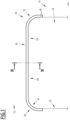
- Figure 1 shows a vehicle 10 according to an embodiment of the invention.
- the vehicle 10 is a land vehicle such as a railway vehicle.
- the vehicle 10 comprises an inner compartment 12 delimited by at least one substantially vertical wall 14.
- Said wall 14 comprises a wall opening 16, giving access to another compartment of the vehicle 10.
- the wall opening 16 is delimited by an edge 18.
- the edge 18 comprises : a horizontal area 20, situated at the top of the wall opening 16 ; a first and a second vertical areas 22, situated on either sides of the wall opening 16 ; and a first and a second curved areas 24, joining the horizontal area 20 respectively with the first and with the second vertical areas 22.
- the vehicle 10 also comprises a lighting device 30, fixed to the edge 18 of the wall opening 16.
- the lighting device 30, shown on Figure 2 comprises : a profile support 32 ; a lighting element 34 ; and a flexible closing band 36.
- the profile support 32 has an elongated shape extending along a tangential direction, between a first and a second ends 38.
- the profile support 32 comprises at least one curved part 40 along the elongated shape.
- the profile support 32 comprises : a rectilinear part 42 ; and a first and a second curved parts 40, disposed respectively at the first and at the second ends 38 of the profile support 32.
- the profile support 32 substantially extends in a single plane including the rectilinear part 42 and the first and second curved parts 40.
- the profile support 32 has a plane of symmetry, corresponding to the cross-sectional plane of Figure 2 .
- the first and second curved parts 40 are symmetrical to one another relative to said plane of symmetry.
- each of the first and second curved parts 40 has a substantially constant curvature and is more preferably arc-shaped.
- the profile support 32 has a substantially constant section, visible on Figure 2 , between the first and second ends 38.
- the profile support 32 comprises : a first 44 and a second 46 compartments ; and an inner wall 48, delimiting the first and second compartments.
- the inner wall 48 is substantially planar. More precisely, in the embodiment of Figures 1 and 2 , the inner wall 48 is substantially perpendicular to the curvatures of the first and second curved parts 40.
- the first 44 and second 46 compartments respectively comprise a first 50 and a second 52 openings, extending between the first and second ends 38 of the profile support 32. At least the first opening 50 is oriented toward the curvatures of the first and second curved parts 40. Preferably, as in the embodiment of Figures 1 and 2 , the first opening 50 is oriented toward the concavity of the first and second curved parts 40. In another embodiment (not shown), the first opening is oriented toward the convexity of at least a curved part.
- the profile support 32 also comprises : a first 54 and a second 56 lateral walls, substantially planar and parallel to the inner wall 48 ; and a first 60 and a second 62 top walls.
- the first top wall 60 extends between the inner wall 48 and the first lateral wall 54, delimiting the first compartment 44.
- the second top wall 62 extends between the inner wall 48 and the second lateral wall 56, delimiting the second compartment 46.
- the first 50 and second 52 openings are disposed opposite, respectively, the first 60 and the second 62 top walls, and are oriented toward the concavity of the first and second curved parts 40.
- the profile support 32 also comprises an abutting band 63 protruding from an end of the second lateral wall 56, opposed to the second top wall 62.
- the abutting band 63 is substantially perpendicular to the second lateral wall 56 and protrudes opposite the second compartment 46.
- the profile support 32 has a general shape corresponding to a shape of the wall opening 16.
- the abutting band 63 has a shape complementary to the edge 18 of the wall opening 16.
- the profile support 32 is metallic, preferably made of aluminum. In another embodiment, the profile support 32 is made of a plastic material.
- the lighting element 34 is a flexible LED strip with an elongated shape. More precisely, the lighting element 34 comprises : a body 64, made of a translucent elastomer; a plurality of LED (not shown) embedded in the body 64 ; and an electrical circuit (not shown) able to supply electricity to the plurality of LED.
- the body 64 comprises a lighting face 66 extending along the elongated shape of the lighting element 34.
- the body 64 of the lighting element 34 is inserted in the first compartment 44 of the profile support 32, so that the first opening 50 of said first compartment 44 opens on the lighting face 66 of said body.
- the profile support 32 comprises a first assembling organ 70 extending in the first compartment 44 between the first and second ends 38 ; and the lighting element 34 comprises a second assembling organ 72 coupled to the first assembling organ 70.
- the second assembling organ 72 is reversibly coupled to the first assembling organ 70, so that the lighting element 34 may be extracted from the first compartment 44, for repair or replacement.
- the first assembling organ 70 is a rib formed on the first top wall 60 ; and the second assembling organ 72 is a groove formed in the body 64, opposite the lighting face 66.
- the closing band 36 has an elongated shape and is made of a deformable material such as an elastomer.
- the closing band 36 is assembled to the second opening 52 so as to close the second compartment 46. More preferably, the closing band 36 is reversibly assembled to the second opening 52 so that the second compartment 46 may be alternatively closed and opened.
- the profile support 32 comprises a third assembling organ 74 extending in the second compartment 46 between the first and second ends 38 ; and the closing band 36 comprises a fourth assembling organ 76 reversibly coupled to the third assembling organ 74.
- the third assembling organ 74 comprises a pair of lips 77, each lip 77 protruding in the second compartment 46, respectively from the inner wall 48 and from the second lateral wall 56 ; and the fourth assembling organ 76 comprises a pair of opposite grooves 78.
- each of the lips 77 is received in one of the grooves 78 and the second opening 52 is obturated by the closing band 36.
- the wall 14 of the vehicle 10 and the lighting device 30 are part of a lighting assembly 80 wherein the lighting device 30 is fixed to the edge 18 of the wall opening 16.
- the lighting assembly 80 also comprises at least one fastener 82, preferably a plurality of fasteners 82.
- the wall 14 and the lighting device 30 are fixed to each other by the at least one fastener 82. More precisely, in the embodiment of Figures 1 and 2 , a first face 84 of the wall 14 is fixed to the second lateral wall 56 of the profile support 32 by the fastener 82.
- the fastener 82 comprises a shaft 86 installed in through hole of the wall 14 and of the second lateral wall 56 of the profile support 32.
- the shaft 86 extends between a first end 88 and a second end, the first end 88 protruding in the second compartment 46.
- the second end of the shaft 86 is made in one piece with a head 90 in contact with a second face 91 of the wall 14.
- the fastener 82 also comprises a coupling element 92 assembled to the first end 88 of the shaft 86 in the second compartment 46.
- the first end 88 of the shaft is threaded and the coupling element 92 is a nut.
- the profile support 32 is for example manufactured by extrusion of an aluminum profile, then by bending the ends of the profile to form the curved parts 40 of the profile support.
- the lighting element 34 and closing band 36 are manufactured by methods involving the extrusion of elastomer materials.
- the second lateral wall 56 of the profile support 32 is applied against the first face 84 of the wall 14, so that the abutting band 63 is in contact with the edge 18. At least one through-hole is then pierced in the wall 14 and second lateral wall 56, and the shaft 86 of the fastener 82 is inserted in said through-hole, the head 90 abutting against the second face 91 of the wall 14.
- the nut 92 is then introduced in the second compartment 46 of the profile support 32, and screwed to the first end 88 of the shaft.
- the piercing of a through-hole and mounting of a corresponding fastener 82 is preferably repeated for a plurality of fasteners 82, disposed along the profile support 32 between the first and second ends 38.
- through-holes are provided in the second lateral wall 56 of the profile support 32 before installing the lighting assembly 80.
- the second assembling organ 72 of the lighting element 34 is then reversibly coupled to the first assembling organ 70 of the profile support 32.
- the groove formed in the body 64 is coupled to the rib formed in the first top wall 60 by deformation of the body 64, or by sliding said body along the rib from an end 38 of the profile support 32.
- the lighting element 34 and profile support 32 are coupled before assembling the profile support to the wall 14.
- the fourth assembling organ 76 of the closing band 36 is then reversibly coupled to the third assembling organ 74 of the profile support 32.
- the grooves 78 formed in the closing band 36 are coupled to the lips 77 of the profile support 32 by deformation of the closing band 36, or by sliding said closing band along the lips 77 from an end 38 of the profile support 32.
- the lighting assembly 80 is then in the installed configuration described above, the wall 14 and the lighting device 30 being fixed to each other by the at least one fastener 82.
- the lighting face 66 of the body 64 of the lighting element is oriented toward the wall opening 16.
- the electrical circuit (not shown) of the lighting element is then connected to a source of electricity, so that the plurality of LED (not shown) embedded in the body 64 is able to provide light to a passage or gangway, formed in the inner compartment 12 by the wall opening 16.
- the closing band 36 closing the second compartment 46 of the profile support 32, improves the esthetics of the lighting assembly 80 by hiding the nuts 92 and the first ends 88 of the threaded shafts 86.
- the invention provides a compact, bended lighting device, with a continuous lighting element without visible break.
- the closing band 36 is dissociated from the profile support 32, so as to give access to the nuts 92.
Landscapes
- Engineering & Computer Science (AREA)
- Mechanical Engineering (AREA)
- General Engineering & Computer Science (AREA)
- Physics & Mathematics (AREA)
- Microelectronics & Electronic Packaging (AREA)
- Optics & Photonics (AREA)
- Non-Portable Lighting Devices Or Systems Thereof (AREA)
- Arrangement Of Elements, Cooling, Sealing, Or The Like Of Lighting Devices (AREA)
- Arrangements Of Lighting Devices For Vehicle Interiors, Mounting And Supporting Thereof, Circuits Therefore (AREA)
Abstract
Description
- The present invention concerns a lighting device, comprising a profile support of elongated shape and a lighting element; the profile support comprising a first and a second compartments separated by an inner wall, the first and the second compartments comprising respectively a first and a second openings extending along the elongated shape of the profile support.
- Inner compartments of vehicles are advantageously provided with compact lighting devices generating a qualitative light effect. Such a lighting device is disclosed in document
US8955998 . - In railway vehicles, the communication between inner compartments is typically formed by gangways with curved archways. It is advantageous to provide such archways with specific lighting devices, in an esthetic and cost-effective manner.
- For this purpose, the invention relates to a lighting device of the aforementioned type, wherein : the profile support comprises at least one curved part along the elongated shape ; the lighting element is a flexible LED strip comprising a body inserted in the first compartment, the body comprising a lighting face arranged so as to face the first opening; and the lighting device also comprises a flexible band assembled to the second opening so as to close the second compartment.
- According to preferred embodiments, the lighting device may include one or more of the following features, considered alone or in any technically possible combination :
- the first opening faces a concavity or a convexity of the at least one curved part of the profile support;
- the profile support comprises a first assembling organ extending along the elongated shape in the first compartment; and the lighting element comprises a second assembling organ coupled to the first assembling organ along the elongated shape ;
- one of the first and second assembling organs comprises a rib and the other of the first and second assembling organs comprises a groove ;
- the second opening faces a concavity or a convexity of the at least one curved part of the profile support;
- the profile support comprises a third assembling organ extending along the elongated shape in the second compartment; and the flexible band comprises a fourth assembling organ coupled to the third assembling organ along the elongated shape ;
- one of the third and fourth assembling organs comprises a lip and the other of the third and fourth assembling organs comprises a groove ;
- the profile support is made of aluminum.
- The invention also relates to a vehicle comprising a substantially vertical wall, said wall comprising a wall opening defined by an edge, said edge comprising at least one curved part, the vehicle also comprising a lighting device as described above, said lighting device being fixed to the edge of the wall opening.
- The invention will be easier to understand in view of the following description, provided solely as an example, and with reference to the appended drawings, wherein :
-
Figure 1 is a detailed, schematic view of a vehicle comprising a lighting device according to an embodiment of the invention ; and -
Figure 2 is a detailed, cross-sectional view of the vehicle and lighting device ofFigure 1 . -
Figure 1 shows avehicle 10 according to an embodiment of the invention. Preferably, thevehicle 10 is a land vehicle such as a railway vehicle. - The
vehicle 10 comprises aninner compartment 12 delimited by at least one substantiallyvertical wall 14. Saidwall 14 comprises a wall opening 16, giving access to another compartment of thevehicle 10. - The wall opening 16 is delimited by an
edge 18. In the embodiment ofFigure 1 , theedge 18 comprises : ahorizontal area 20, situated at the top of the wall opening 16 ; a first and a secondvertical areas 22, situated on either sides of the wall opening 16 ; and a first and a secondcurved areas 24, joining thehorizontal area 20 respectively with the first and with the secondvertical areas 22. - The
vehicle 10 also comprises alighting device 30, fixed to theedge 18 of the wall opening 16. - The
lighting device 30, shown onFigure 2 , comprises : aprofile support 32 ; alighting element 34 ; and aflexible closing band 36. - The
profile support 32 has an elongated shape extending along a tangential direction, between a first and asecond ends 38. - The
profile support 32 comprises at least onecurved part 40 along the elongated shape. In the embodiment ofFigures 1 and2 , theprofile support 32 comprises : arectilinear part 42 ; and a first and a secondcurved parts 40, disposed respectively at the first and at thesecond ends 38 of theprofile support 32. - In the embodiment of
Figures 1 and2 , theprofile support 32 substantially extends in a single plane including therectilinear part 42 and the first and secondcurved parts 40. - In the embodiment of
Figures 1 and2 , theprofile support 32 has a plane of symmetry, corresponding to the cross-sectional plane ofFigure 2 . The first and secondcurved parts 40 are symmetrical to one another relative to said plane of symmetry. - Preferably, each of the first and second
curved parts 40 has a substantially constant curvature and is more preferably arc-shaped. - The
profile support 32 has a substantially constant section, visible onFigure 2 , between the first andsecond ends 38. - In particular, the
profile support 32 comprises : a first 44 and a second 46 compartments ; and aninner wall 48, delimiting the first and second compartments. In the embodiment ofFigures 1 and2 , theinner wall 48 is substantially planar. More precisely, in the embodiment ofFigures 1 and2 , theinner wall 48 is substantially perpendicular to the curvatures of the first and secondcurved parts 40. - The first 44 and second 46 compartments respectively comprise a first 50 and a second 52 openings, extending between the first and
second ends 38 of theprofile support 32. At least thefirst opening 50 is oriented toward the curvatures of the first and secondcurved parts 40. Preferably, as in the embodiment ofFigures 1 and2 , thefirst opening 50 is oriented toward the concavity of the first and secondcurved parts 40. In another embodiment (not shown), the first opening is oriented toward the convexity of at least a curved part. - In the embodiment of
Figures 1 and2 , theprofile support 32 also comprises : a first 54 and a second 56 lateral walls, substantially planar and parallel to theinner wall 48 ; and a first 60 and a second 62 top walls. The firsttop wall 60 extends between theinner wall 48 and the firstlateral wall 54, delimiting thefirst compartment 44. The secondtop wall 62 extends between theinner wall 48 and the secondlateral wall 56, delimiting thesecond compartment 46. The first 50 and second 52 openings are disposed opposite, respectively, the first 60 and the second 62 top walls, and are oriented toward the concavity of the first and secondcurved parts 40. - In the embodiment of
Figures 1 and2 , theprofile support 32 also comprises anabutting band 63 protruding from an end of the secondlateral wall 56, opposed to the secondtop wall 62. The abuttingband 63 is substantially perpendicular to the secondlateral wall 56 and protrudes opposite thesecond compartment 46. - The
profile support 32 has a general shape corresponding to a shape of the wall opening 16. In particular, in the embodiment ofFigures 1 and2 , theabutting band 63 has a shape complementary to theedge 18 of the wall opening 16. - In an embodiment, the
profile support 32 is metallic, preferably made of aluminum. In another embodiment, theprofile support 32 is made of a plastic material. - The
lighting element 34 is a flexible LED strip with an elongated shape. More precisely, thelighting element 34 comprises : abody 64, made of a translucent elastomer; a plurality of LED (not shown) embedded in thebody 64 ; and an electrical circuit (not shown) able to supply electricity to the plurality of LED. - The
body 64 comprises alighting face 66 extending along the elongated shape of thelighting element 34. - The
body 64 of thelighting element 34 is inserted in thefirst compartment 44 of theprofile support 32, so that the first opening 50 of saidfirst compartment 44 opens on thelighting face 66 of said body. - Preferably, the
profile support 32 comprises a first assemblingorgan 70 extending in thefirst compartment 44 between the first andsecond ends 38 ; and thelighting element 34 comprises a second assemblingorgan 72 coupled to the first assemblingorgan 70. - In an embodiment, the second assembling
organ 72 is reversibly coupled to the first assemblingorgan 70, so that thelighting element 34 may be extracted from thefirst compartment 44, for repair or replacement. - In the embodiment of
Figures 1 and2 , the first assemblingorgan 70 is a rib formed on the firsttop wall 60 ; and the second assemblingorgan 72 is a groove formed in thebody 64, opposite thelighting face 66. - The
closing band 36 has an elongated shape and is made of a deformable material such as an elastomer. - The
closing band 36 is assembled to the second opening 52 so as to close thesecond compartment 46. More preferably, theclosing band 36 is reversibly assembled to the second opening 52 so that thesecond compartment 46 may be alternatively closed and opened. - Preferably, the
profile support 32 comprises a third assemblingorgan 74 extending in thesecond compartment 46 between the first andsecond ends 38 ; and theclosing band 36 comprises a fourth assemblingorgan 76 reversibly coupled to the third assemblingorgan 74. - In the embodiment of
Figures 1 and2 , the third assemblingorgan 74 comprises a pair oflips 77, eachlip 77 protruding in thesecond compartment 46, respectively from theinner wall 48 and from the secondlateral wall 56 ; and the fourth assemblingorgan 76 comprises a pair ofopposite grooves 78. In an assembled configuration, shown onFigure 2 , each of thelips 77 is received in one of thegrooves 78 and thesecond opening 52 is obturated by theclosing band 36. - In the embodiment of
Figures 1 and2 , thewall 14 of thevehicle 10 and thelighting device 30 are part of alighting assembly 80 wherein thelighting device 30 is fixed to theedge 18 of the wall opening 16. - The
lighting assembly 80 also comprises at least onefastener 82, preferably a plurality offasteners 82. In an installed configuration of thelighting assembly 80, shown onFigures 1 and2 , thewall 14 and thelighting device 30 are fixed to each other by the at least onefastener 82. More precisely, in the embodiment ofFigures 1 and2 , afirst face 84 of thewall 14 is fixed to the secondlateral wall 56 of theprofile support 32 by thefastener 82. - In the embodiment of
Figures 1 and2 , thefastener 82 comprises ashaft 86 installed in through hole of thewall 14 and of the secondlateral wall 56 of theprofile support 32. Theshaft 86 extends between afirst end 88 and a second end, thefirst end 88 protruding in thesecond compartment 46. Preferably, the second end of theshaft 86 is made in one piece with ahead 90 in contact with asecond face 91 of thewall 14. - Preferably, the
fastener 82 also comprises acoupling element 92 assembled to thefirst end 88 of theshaft 86 in thesecond compartment 46. For example, thefirst end 88 of the shaft is threaded and thecoupling element 92 is a nut. - A method for manufacturing the
lighting device 30 and installing thelighting assembly 80 will now be described. Theprofile support 32 is for example manufactured by extrusion of an aluminum profile, then by bending the ends of the profile to form thecurved parts 40 of the profile support. Thelighting element 34 andclosing band 36 are manufactured by methods involving the extrusion of elastomer materials. - The second
lateral wall 56 of theprofile support 32 is applied against thefirst face 84 of thewall 14, so that the abuttingband 63 is in contact with theedge 18. At least one through-hole is then pierced in thewall 14 and secondlateral wall 56, and theshaft 86 of thefastener 82 is inserted in said through-hole, thehead 90 abutting against thesecond face 91 of thewall 14. - The
nut 92 is then introduced in thesecond compartment 46 of theprofile support 32, and screwed to thefirst end 88 of the shaft. - The piercing of a through-hole and mounting of a corresponding
fastener 82 is preferably repeated for a plurality offasteners 82, disposed along theprofile support 32 between the first and second ends 38. - In an alternate embodiment, through-holes are provided in the second
lateral wall 56 of theprofile support 32 before installing thelighting assembly 80. - The second assembling
organ 72 of thelighting element 34 is then reversibly coupled to the first assemblingorgan 70 of theprofile support 32. For example, the groove formed in thebody 64 is coupled to the rib formed in the firsttop wall 60 by deformation of thebody 64, or by sliding said body along the rib from anend 38 of theprofile support 32. - In an alternate embodiment, the
lighting element 34 andprofile support 32 are coupled before assembling the profile support to thewall 14. - The fourth assembling
organ 76 of theclosing band 36 is then reversibly coupled to the third assemblingorgan 74 of theprofile support 32. For example, thegrooves 78 formed in theclosing band 36 are coupled to thelips 77 of theprofile support 32 by deformation of theclosing band 36, or by sliding said closing band along thelips 77 from anend 38 of theprofile support 32. - The
lighting assembly 80 is then in the installed configuration described above, thewall 14 and thelighting device 30 being fixed to each other by the at least onefastener 82. Thelighting face 66 of thebody 64 of the lighting element is oriented toward thewall opening 16. - The electrical circuit (not shown) of the lighting element is then connected to a source of electricity, so that the plurality of LED (not shown) embedded in the
body 64 is able to provide light to a passage or gangway, formed in theinner compartment 12 by thewall opening 16. - The
closing band 36, closing thesecond compartment 46 of theprofile support 32, improves the esthetics of thelighting assembly 80 by hiding the nuts 92 and the first ends 88 of the threadedshafts 86. - The invention provides a compact, bended lighting device, with a continuous lighting element without visible break.
- In case the
lighting device 30 needs to be removed from thewall 14 for maintenance, theclosing band 36 is dissociated from theprofile support 32, so as to give access to the nuts 92.
Claims (9)
- Lighting device (30), comprising : a profile support (32) of elongated shape ; and a lighting element (34) ;the profile support (32) comprising a first (44) and a second (46) compartments separated by an inner wall (48), the first and the second compartments comprising respectively a first (50) and a second (52) openings extending along the elongated shape of the profile support (32) ;the lighting device (30) being characterized in that:- the profile support (32) comprises at least one curved part (40) along the elongated shape ;- the lighting element (34) is a flexible LED strip comprising a body (64) inserted in the first compartment, the body comprising a lighting face (66) arranged so as to face the first opening (50) ; and- the lighting device also comprises a flexible band (36) assembled to the second opening (52) so as to close the second compartment (46).
- Lighting device (30) according to claim 1, wherein the first opening (50) faces a concavity or a convexity of the at least one curved part (40) of the profile support (32).
- Lighting device (30) according to claim 1 or 2, wherein the profile support (32) comprises a first assembling organ (70) extending along the elongated shape in the first compartment (44) ; and the lighting element (34) comprises a second assembling organ (72) coupled to the first assembling organ (70) along the elongated shape.
- Lighting device (30) according to claim 3, wherein one (70) of the first and second assembling organs comprises a rib and the other (72) of the first and second assembling organs comprises a groove.
- Lighting device (30) according to any one of the previous claims, wherein the second opening (52) faces a concavity or a convexity of the at least one curved part (40) of the profile support (32).
- Lighting device (30) according to any one of the previous claims, wherein the profile support (32) comprises a third assembling organ (74) extending along the elongated shape in the second compartment (46) ; and the flexible band (36) comprises a fourth assembling organ (76) coupled to the third assembling organ (74) along the elongated shape.
- Lighting device (30) according to claim 6, wherein one (74) of the third and fourth assembling organs comprises a lip (77) and the other (76) of the third and fourth assembling organs comprises a groove (78).
- Lighting device (30) according to any one of the previous claims, wherein the profile support (32) is made of aluminum.
- Vehicle (10) comprising a substantially vertical wall (14), said wall comprising a wall opening (16) defined by an edge (18), said edge comprising at least one curved part (24), the vehicle also comprising a lighting device (30) according to any one of the previous claims, said lighting device being fixed to the edge (18) of the wall opening.
Priority Applications (3)
| Application Number | Priority Date | Filing Date | Title |
|---|---|---|---|
| PL23306375.9T PL4509362T3 (en) | 2023-08-14 | 2023-08-14 | Elongated lighting device for vehicle |
| EP23306375.9A EP4509362B1 (en) | 2023-08-14 | 2023-08-14 | Elongated lighting device for vehicle |
| ES23306375T ES3066438T3 (en) | 2023-08-14 | 2023-08-14 | Elongated lighting device for vehicle |
Applications Claiming Priority (1)
| Application Number | Priority Date | Filing Date | Title |
|---|---|---|---|
| EP23306375.9A EP4509362B1 (en) | 2023-08-14 | 2023-08-14 | Elongated lighting device for vehicle |
Publications (2)
| Publication Number | Publication Date |
|---|---|
| EP4509362A1 true EP4509362A1 (en) | 2025-02-19 |
| EP4509362B1 EP4509362B1 (en) | 2026-03-04 |
Family
ID=87929253
Family Applications (1)
| Application Number | Title | Priority Date | Filing Date |
|---|---|---|---|
| EP23306375.9A Active EP4509362B1 (en) | 2023-08-14 | 2023-08-14 | Elongated lighting device for vehicle |
Country Status (3)
| Country | Link |
|---|---|
| EP (1) | EP4509362B1 (en) |
| ES (1) | ES3066438T3 (en) |
| PL (1) | PL4509362T3 (en) |
Citations (10)
| Publication number | Priority date | Publication date | Assignee | Title |
|---|---|---|---|---|
| EP1533205A1 (en) * | 2003-11-18 | 2005-05-25 | Tokyu Car Corporation | Vehicle with a door step comprising a security lighting. |
| US20100277898A1 (en) * | 2009-04-30 | 2010-11-04 | Lippert Components, Inc. | Threshold Lighting System |
| JP4597786B2 (en) * | 2005-06-13 | 2010-12-15 | 東急車輛製造株式会社 | Vehicle lighting device |
| US8955998B2 (en) | 2011-07-22 | 2015-02-17 | Led House Sdn Bhd | Lighting assembly for ceiling board |
| CN104554031A (en) * | 2013-10-28 | 2015-04-29 | 常州市三叶车辆配件厂 | Automobile pedal |
| US20170072841A1 (en) * | 2015-09-10 | 2017-03-16 | Schott Ag | Linear illumination device |
| CN210891186U (en) * | 2019-10-28 | 2020-06-30 | 中山市致派照明科技有限公司 | Modeling lamp with double-sided triangular aluminum profile and double-sided double-color light emitting |
| WO2021083611A1 (en) * | 2019-10-31 | 2021-05-06 | Gebr. Bode Gmbh & Co. Kg | Door leaf comprising a light profile for a vehicle |
| US11167691B1 (en) * | 2020-12-10 | 2021-11-09 | Fca Us Llc | Vehicle utility rail with integrated lights |
| DE202022103749U1 (en) * | 2022-07-05 | 2022-07-19 | Knaus Tabbert Ag | cover profile |
-
2023
- 2023-08-14 ES ES23306375T patent/ES3066438T3/en active Active
- 2023-08-14 PL PL23306375.9T patent/PL4509362T3/en unknown
- 2023-08-14 EP EP23306375.9A patent/EP4509362B1/en active Active
Patent Citations (10)
| Publication number | Priority date | Publication date | Assignee | Title |
|---|---|---|---|---|
| EP1533205A1 (en) * | 2003-11-18 | 2005-05-25 | Tokyu Car Corporation | Vehicle with a door step comprising a security lighting. |
| JP4597786B2 (en) * | 2005-06-13 | 2010-12-15 | 東急車輛製造株式会社 | Vehicle lighting device |
| US20100277898A1 (en) * | 2009-04-30 | 2010-11-04 | Lippert Components, Inc. | Threshold Lighting System |
| US8955998B2 (en) | 2011-07-22 | 2015-02-17 | Led House Sdn Bhd | Lighting assembly for ceiling board |
| CN104554031A (en) * | 2013-10-28 | 2015-04-29 | 常州市三叶车辆配件厂 | Automobile pedal |
| US20170072841A1 (en) * | 2015-09-10 | 2017-03-16 | Schott Ag | Linear illumination device |
| CN210891186U (en) * | 2019-10-28 | 2020-06-30 | 中山市致派照明科技有限公司 | Modeling lamp with double-sided triangular aluminum profile and double-sided double-color light emitting |
| WO2021083611A1 (en) * | 2019-10-31 | 2021-05-06 | Gebr. Bode Gmbh & Co. Kg | Door leaf comprising a light profile for a vehicle |
| US11167691B1 (en) * | 2020-12-10 | 2021-11-09 | Fca Us Llc | Vehicle utility rail with integrated lights |
| DE202022103749U1 (en) * | 2022-07-05 | 2022-07-19 | Knaus Tabbert Ag | cover profile |
Also Published As
| Publication number | Publication date |
|---|---|
| ES3066438T3 (en) | 2026-05-13 |
| PL4509362T3 (en) | 2026-07-13 |
| EP4509362B1 (en) | 2026-03-04 |
Similar Documents
| Publication | Publication Date | Title |
|---|---|---|
| US8556451B1 (en) | Linear lighting fixture | |
| US8371531B2 (en) | Aircraft cabin window assembly method | |
| EP2726784B1 (en) | Luminaire with a potting compound | |
| EP0197070A4 (en) | Strip lighting fixture for mass transit vehicles. | |
| DE202009015404U1 (en) | Wall and ceiling system | |
| JP6308457B2 (en) | Light source unit and lighting apparatus | |
| US10344925B2 (en) | Elongated lighting device having a curved shape and method for manufacturing | |
| US6453841B1 (en) | Windshield bottom trim | |
| CA3058851A1 (en) | Outdoor light fixtures | |
| KR19990081988A (en) | Flexible glass actuator with rigid molded support | |
| US5791764A (en) | Fluorescent light fixture with extruded wire way cover mount | |
| EP4509362B1 (en) | Elongated lighting device for vehicle | |
| EP2647907B1 (en) | Light insert with reflector | |
| US20130294090A1 (en) | Door assembly for a light fixture | |
| US20070075187A1 (en) | Window frame for aircraft | |
| DE102017001173A1 (en) | Fridge and / or freezer | |
| EP2203677B1 (en) | Lamp with two front parts | |
| DE102013100249A1 (en) | Window, door or facade component for building, has profiles receiving surface element and comprising glass folding part in which glass folding elements are arranged, where glass folding elements are transparent light from light source | |
| WO2009041141A1 (en) | Door panel | |
| DE102019112687A1 (en) | Tub-shaped luminaire housing | |
| RU2140860C1 (en) | Spoiler with signal light | |
| US20150078019A1 (en) | Light strip for a passenger compartment of a rail vehicle | |
| US20040056739A1 (en) | Waveguide | |
| EP3807542A1 (en) | A connection device and a box arrangement provided with such connection device | |
| CN208504008U (en) | A kind of line lamp of lamp plate easy to disassemble |
Legal Events
| Date | Code | Title | Description |
|---|---|---|---|
| PUAI | Public reference made under article 153(3) epc to a published international application that has entered the european phase |
Free format text: ORIGINAL CODE: 0009012 |
|
| STAA | Information on the status of an ep patent application or granted ep patent |
Free format text: STATUS: THE APPLICATION HAS BEEN PUBLISHED |
|
| STAA | Information on the status of an ep patent application or granted ep patent |
Free format text: STATUS: REQUEST FOR EXAMINATION WAS MADE |
|
| AK | Designated contracting states |
Kind code of ref document: A1 Designated state(s): AL AT BE BG CH CY CZ DE DK EE ES FI FR GB GR HR HU IE IS IT LI LT LU LV MC ME MK MT NL NO PL PT RO RS SE SI SK SM TR |
|
| 17P | Request for examination filed |
Effective date: 20250123 |
|
| RIC1 | Information provided on ipc code assigned before grant |
Ipc: B60Q 3/217 20170101AFI20250825BHEP Ipc: B60Q 3/41 20170101ALI20250825BHEP Ipc: B60Q 3/78 20170101ALI20250825BHEP Ipc: B61D 29/00 20060101ALI20250825BHEP Ipc: F21S 43/14 20180101ALI20250825BHEP Ipc: F21S 43/15 20180101ALI20250825BHEP Ipc: F21S 4/22 20160101ALI20250825BHEP Ipc: F21W 106/00 20180101ALN20250825BHEP Ipc: F21Y 103/10 20160101ALN20250825BHEP Ipc: F21Y 115/10 20160101ALN20250825BHEP |
|
| GRAP | Despatch of communication of intention to grant a patent |
Free format text: ORIGINAL CODE: EPIDOSNIGR1 |
|
| STAA | Information on the status of an ep patent application or granted ep patent |
Free format text: STATUS: GRANT OF PATENT IS INTENDED |
|
| RIC1 | Information provided on ipc code assigned before grant |
Ipc: B60Q 3/217 20170101AFI20250908BHEP Ipc: B60Q 3/41 20170101ALI20250908BHEP Ipc: B60Q 3/78 20170101ALI20250908BHEP Ipc: B61D 29/00 20060101ALI20250908BHEP Ipc: F21S 43/14 20180101ALI20250908BHEP Ipc: F21S 43/15 20180101ALI20250908BHEP Ipc: F21S 4/22 20160101ALI20250908BHEP Ipc: F21W 106/00 20180101ALN20250908BHEP Ipc: F21Y 103/10 20160101ALN20250908BHEP Ipc: F21Y 115/10 20160101ALN20250908BHEP |
|
| RIC1 | Information provided on ipc code assigned before grant |
Ipc: B60Q 3/217 20170101AFI20250922BHEP Ipc: B60Q 3/41 20170101ALI20250922BHEP Ipc: B60Q 3/78 20170101ALI20250922BHEP Ipc: B61D 29/00 20060101ALI20250922BHEP Ipc: F21S 43/14 20180101ALI20250922BHEP Ipc: F21S 43/15 20180101ALI20250922BHEP Ipc: F21S 4/22 20160101ALI20250922BHEP Ipc: F21W 106/00 20180101ALN20250922BHEP Ipc: F21Y 103/10 20160101ALN20250922BHEP Ipc: F21Y 115/10 20160101ALN20250922BHEP |
|
| INTG | Intention to grant announced |
Effective date: 20251008 |
|
| GRAS | Grant fee paid |
Free format text: ORIGINAL CODE: EPIDOSNIGR3 |
|
| GRAA | (expected) grant |
Free format text: ORIGINAL CODE: 0009210 |
|
| STAA | Information on the status of an ep patent application or granted ep patent |
Free format text: STATUS: THE PATENT HAS BEEN GRANTED |
|
| AK | Designated contracting states |
Kind code of ref document: B1 Designated state(s): AL AT BE BG CH CY CZ DE DK EE ES FI FR GB GR HR HU IE IS IT LI LT LU LV MC ME MK MT NL NO PL PT RO RS SE SI SK SM TR |
|
| REG | Reference to a national code |
Ref country code: CH Ref legal event code: F10 Free format text: ST27 STATUS EVENT CODE: U-0-0-F10-F00 (AS PROVIDED BY THE NATIONAL OFFICE) Effective date: 20260304 Ref country code: GB Ref legal event code: FG4D |
|
| REG | Reference to a national code |
Ref country code: IE Ref legal event code: FG4D |
|
| REG | Reference to a national code |
Ref country code: DE Ref legal event code: R096 Ref document number: 602023012968 Country of ref document: DE |
|
| REG | Reference to a national code |
Ref country code: ES Ref legal event code: FG2A Ref document number: 3066438 Country of ref document: ES Kind code of ref document: T3 Effective date: 20260513 |
|
| PG25 | Lapsed in a contracting state [announced via postgrant information from national office to epo] |
Ref country code: RS Free format text: LAPSE BECAUSE OF FAILURE TO SUBMIT A TRANSLATION OF THE DESCRIPTION OR TO PAY THE FEE WITHIN THE PRESCRIBED TIME-LIMIT Effective date: 20260604 |
|
| REG | Reference to a national code |
Ref country code: NL Ref legal event code: MP Effective date: 20260304 |
|
| PG25 | Lapsed in a contracting state [announced via postgrant information from national office to epo] |
Ref country code: GR Free format text: LAPSE BECAUSE OF FAILURE TO SUBMIT A TRANSLATION OF THE DESCRIPTION OR TO PAY THE FEE WITHIN THE PRESCRIBED TIME-LIMIT Effective date: 20260605 |
|
| REG | Reference to a national code |
Ref country code: LT Ref legal event code: MG9D |
|
| PG25 | Lapsed in a contracting state [announced via postgrant information from national office to epo] |
Ref country code: LT Free format text: LAPSE BECAUSE OF FAILURE TO SUBMIT A TRANSLATION OF THE DESCRIPTION OR TO PAY THE FEE WITHIN THE PRESCRIBED TIME-LIMIT Effective date: 20260304 |
|
| PG25 | Lapsed in a contracting state [announced via postgrant information from national office to epo] |
Ref country code: NO Free format text: LAPSE BECAUSE OF FAILURE TO SUBMIT A TRANSLATION OF THE DESCRIPTION OR TO PAY THE FEE WITHIN THE PRESCRIBED TIME-LIMIT Effective date: 20260604 |
|
| P01 | Opt-out of the competence of the unified patent court (upc) registered |
Free format text: CASE NUMBER: UPC_APP_0018022_4509362/2026 Effective date: 20260610 |
|
| PG25 | Lapsed in a contracting state [announced via postgrant information from national office to epo] |
Ref country code: FI Free format text: LAPSE BECAUSE OF FAILURE TO SUBMIT A TRANSLATION OF THE DESCRIPTION OR TO PAY THE FEE WITHIN THE PRESCRIBED TIME-LIMIT Effective date: 20260304 Ref country code: SE Free format text: LAPSE BECAUSE OF FAILURE TO SUBMIT A TRANSLATION OF THE DESCRIPTION OR TO PAY THE FEE WITHIN THE PRESCRIBED TIME-LIMIT Effective date: 20260304 |
|
| PG25 | Lapsed in a contracting state [announced via postgrant information from national office to epo] |
Ref country code: HR Free format text: LAPSE BECAUSE OF FAILURE TO SUBMIT A TRANSLATION OF THE DESCRIPTION OR TO PAY THE FEE WITHIN THE PRESCRIBED TIME-LIMIT Effective date: 20260304 |
|
| PG25 | Lapsed in a contracting state [announced via postgrant information from national office to epo] |
Ref country code: LV Free format text: LAPSE BECAUSE OF FAILURE TO SUBMIT A TRANSLATION OF THE DESCRIPTION OR TO PAY THE FEE WITHIN THE PRESCRIBED TIME-LIMIT Effective date: 20260304 |
|
| PG25 | Lapsed in a contracting state [announced via postgrant information from national office to epo] |
Ref country code: BG Free format text: LAPSE BECAUSE OF FAILURE TO SUBMIT A TRANSLATION OF THE DESCRIPTION OR TO PAY THE FEE WITHIN THE PRESCRIBED TIME-LIMIT Effective date: 20260304 |