EP4509343A2 - Constant tension snap-fit assembly - Google Patents
Constant tension snap-fit assembly Download PDFInfo
- Publication number
- EP4509343A2 EP4509343A2 EP25150079.9A EP25150079A EP4509343A2 EP 4509343 A2 EP4509343 A2 EP 4509343A2 EP 25150079 A EP25150079 A EP 25150079A EP 4509343 A2 EP4509343 A2 EP 4509343A2
- Authority
- EP
- European Patent Office
- Prior art keywords
- component
- nozzle
- assembly
- operating conditions
- end cap
- Prior art date
- Legal status (The legal status is an assumption and is not a legal conclusion. Google has not performed a legal analysis and makes no representation as to the accuracy of the status listed.)
- Pending
Links
Images





Classifications
-
- F—MECHANICAL ENGINEERING; LIGHTING; HEATING; WEAPONS; BLASTING
- F04—POSITIVE - DISPLACEMENT MACHINES FOR LIQUIDS; PUMPS FOR LIQUIDS OR ELASTIC FLUIDS
- F04F—PUMPING OF FLUID BY DIRECT CONTACT OF ANOTHER FLUID OR BY USING INERTIA OF FLUID TO BE PUMPED; SIPHONS
- F04F5/00—Jet pumps, i.e. devices in which flow is induced by pressure drop caused by velocity of another fluid flow
- F04F5/44—Component parts, details, or accessories not provided for in, or of interest apart from, groups F04F5/02 - F04F5/42
- F04F5/46—Arrangements of nozzles
-
- F—MECHANICAL ENGINEERING; LIGHTING; HEATING; WEAPONS; BLASTING
- F02—COMBUSTION ENGINES; HOT-GAS OR COMBUSTION-PRODUCT ENGINE PLANTS
- F02M—SUPPLYING COMBUSTION ENGINES IN GENERAL WITH COMBUSTIBLE MIXTURES OR CONSTITUENTS THEREOF
- F02M37/00—Apparatus or systems for feeding liquid fuel from storage containers to carburettors or fuel-injection apparatus; Arrangements for purifying liquid fuel specially adapted for, or arranged on, internal-combustion engines
- F02M37/02—Feeding by means of suction apparatus, e.g. by air flow through carburettors
- F02M37/025—Feeding by means of a liquid fuel-driven jet pump
-
- B—PERFORMING OPERATIONS; TRANSPORTING
- B60—VEHICLES IN GENERAL
- B60K—ARRANGEMENT OR MOUNTING OF PROPULSION UNITS OR OF TRANSMISSIONS IN VEHICLES; ARRANGEMENT OR MOUNTING OF PLURAL DIVERSE PRIME-MOVERS IN VEHICLES; AUXILIARY DRIVES FOR VEHICLES; INSTRUMENTATION OR DASHBOARDS FOR VEHICLES; ARRANGEMENTS IN CONNECTION WITH COOLING, AIR INTAKE, GAS EXHAUST OR FUEL SUPPLY OF PROPULSION UNITS IN VEHICLES
- B60K15/00—Arrangement in connection with fuel supply of combustion engines or other fuel consuming energy converters, e.g. fuel cells; Mounting or construction of fuel tanks
- B60K15/03—Fuel tanks
- B60K2015/03243—Fuel tanks characterised by special pumps, the mounting thereof
- B60K2015/0325—Jet pumps
-
- F—MECHANICAL ENGINEERING; LIGHTING; HEATING; WEAPONS; BLASTING
- F02—COMBUSTION ENGINES; HOT-GAS OR COMBUSTION-PRODUCT ENGINE PLANTS
- F02M—SUPPLYING COMBUSTION ENGINES IN GENERAL WITH COMBUSTIBLE MIXTURES OR CONSTITUENTS THEREOF
- F02M25/00—Engine-pertinent apparatus for adding non-fuel substances or small quantities of secondary fuel to combustion-air, main fuel or fuel-air mixture
- F02M25/08—Engine-pertinent apparatus for adding non-fuel substances or small quantities of secondary fuel to combustion-air, main fuel or fuel-air mixture adding fuel vapours drawn from engine fuel reservoir
- F02M2025/0863—Engine-pertinent apparatus for adding non-fuel substances or small quantities of secondary fuel to combustion-air, main fuel or fuel-air mixture adding fuel vapours drawn from engine fuel reservoir with means dealing with condensed fuel or water, e.g. having a liquid trap
Definitions
- the first component is a housing of a vapor valve assembly, such as a liquid trap assembly having the recesses
- the second component is an end cap with the extensions.
- the housing and end cap can be configured to support a jet pump assembly so that the constant bias of the rim and resultant forces on the housing and the end cap provide axial forces on the jet pump assembly preventing relative movement of a jet pump nozzle and a nozzle carrier.
- FIG. 1 shows a liquid trap assembly 10 that efficiently drains liquid collected from vapor.
- the liquid trap assembly 10 can also be referred to as an active liquid drain.
- the liquid trap assembly 10 has a housing 12.
- the housing 12 has a first port, referred to as a vapor flow inlet 14 (shown in Figure 2 ) and a second port, referred to as a vapor flow outlet 16 in fluid communication with an interior cavity 18 formed at least in part by the housing 12.
- the outlet 16 is formed by an upper cap 13 secured to the housing 12 with tabs 15 fit through tab retainers 17. Vapor flows from the vapor flow inlet 14, through the cavity 18, to the vapor flow outlet 16.
- Liquid entrained in the vapor flow is collected in a liquid trap 20 formed by the housing 12 at the bottom of the housing 12.
- a filter 19 extends across the lowest portion of the trap 20.
- the outlet 16 can be replaced by an outlet valve, or the housing 12 can have no outlet.
- An end cap 23 is connected to the housing 12 in a manner described herein.
- the housing 12 can be a one-piece, molded plastic component.
- the end cap 23 can also be a one-piece, molded plastic component. Either or both of the housing 12 and an end cap 23 described can have features that promote separation of liquid and vapor, such as baffles and ribs.
- the end cap 23 is referred to as a first component of the liquid trap assembly 10
- the housing 12 is referred to as a second component of the liquid trap assembly 10.
- the liquid trap assembly 10 can be used in many applications. In one application described herein, the liquid trap assembly 10 is used in a fuel vapor recovery system 21 on a vehicle, shown schematically in Figure 9 .
- the vehicle can be a diesel, gasoline, or hybrid application.
- Vapor is vented from a fuel tank 22 that contains liquid fuel 93. The vapor is vented through a vapor vent valve 26 that may provide pressure relief, rollover shutoff, and other functions. Vapor flows from the vapor vent valve 26 to the liquid trap assembly 10 through the inlet 14 and exits through the outlet 16 to a vapor recovery device, such as a canister (C) 28 filled with carbon granules.
- the canister 28 is periodically purged to an engine (E) 30.
- the liquid trap assembly 10 is shown mounted within the fuel tank 22. Alternatively, the liquid trap assembly 10 can be external to the fuel tank 22.
- the housing 12 forms a first opening 35 in a sidewall adjacent to the liquid trap 20.
- the opening 35 is selectively closed by a check valve 36.
- Any type of valve can be used to close the opening 35, or there can be no valve at the opening 35.
- the check valve 36 includes a valve body 38 and a spring 40 that biases the valve body 38 into the first opening 35 to close the opening 35 and separate the cavity 18 and liquid trap 20 from a valve cavity 42 in which the spring 40 and valve body 38 are movable, as described herein.
- the valve body 38 is generally annular and has a generally cone-shaped end that extends into the cavity 18.
- the spring 40 has a diameter that fits inside the generally annular valve body 38.
- a valve body with a different shape can also be used. For example, a ball valve may be used to close the opening 35.
- the liquid trap assembly 10 includes a jet pump assembly 44.
- the jet pump assembly 44 includes a nozzle carrier 46 and a venturi nozzle 48.
- the nozzle carrier 46 has an entrance port 50 that extends through a generally annular outer wall 55 of the nozzle carrier 46 in operative fluid communication with the liquid trap 20, as best shown in Figure 1 . That is, a lower extent 53 of the cavity 42 is in communication with the entrance port 50.
- the valve 36 opens, the spring 40 depresses, and the valve body 38 will move past the lower extent 53 (to the left in Figure 1 ) so that the liquid trap 20 empties to the lower extent 53 and through the entrance port 50 into a longitudinal passage 52 (shown in Figure 3 ) of the nozzle carrier 46.
- the longitudinal passage 52 extends completely through the nozzle carrier 46 as best shown in Figures 3 and 7 , and is larger in the carrier portion 54 than in the diffuser portion 58.
- the longitudinal passage 52 is in fluid communication with the entrance port 50.
- the valve 36 is configured to prevent draining of the liquid trap 20 by the jet pump assembly 44 when a pressure differential created by liquid flow through the venturi nozzle 48 is below a predetermined level, and to allow fluid communication between the jet pump assembly 44 and the liquid trap 20 when the pressure differential is above the predetermined level. It should be appreciated, however, that the valve 36 is optional, and the jet pump assembly 44 could drain the liquid trap 20 sufficiently if no valve 36 was present.
- the jet pump assembly 44 is connected by tubing 90, 94 to a fuel pump 92 submerged in the liquid fuel 93.
- the fuel pump 92 is also connected to the engine 30 via fuel discharge tubing 94.
- Fuel is discharged from the fuel pump 92 at relatively high pressure through the fuel discharge tubing 94.
- the tubing 90 branches from the fuel discharge tubing 94, providing relatively high pressure liquid fuel flow to an inlet portion 63 of the housing 12 that is in fluid communication with an inlet 64 of the nozzle 48 indicated in Figure 3 .
- the jet pump assembly 44 utilizes high pressure fluid from the fuel pump 92 which flows through the nozzle 48 with a high velocity.
- the flow through the nozzle 48 is referred to as the primary flow or primary stream.
- the high velocity fluid leaving the nozzle 48 creates a low pressure or a vacuum in the area adjacent the nozzle 48, such as at the entrance port 50.
- the pressure differential between the high pressure fluid exiting the nozzle 48 and the lower extent 53 of the cavity 42 adjacent the nozzle 48 induces flow, such as through the entrance port 50, referred to as an induced stream or secondary flow.
- the jet pump assembly 44 has an optional pressure reducer 61 located in the passage 57 formed by the inlet portion 63 of the housing 12, upstream of the inlet 64 and the nozzle 48.
- the pressure reducer 61 can instead be located further upstream of the jet pump assembly 44 such as in a vent line leading to the jet pump assembly 44.
- the pressure reducer 61 reduces pressure and volume flow rate of fluid flow through the inlet portion 63 to the nozzle 48, while increasing velocity of flow through the nozzle 48.
- a diffuser portion 58 of the nozzle carrier 46 is shown in Figure 3 supported by the housing 12.
- the longitudinal passage 52 in the diffuser portion 58 is in fluid communication with a diffuser passage 59 formed by an outlet 65 of the housing 12 (best shown in Figure 1 ) to increase pressure and reduce velocity of the fluid.
- Many factors affect the performance and efficiency of the jet pump assembly 44, including fluid molecular weight, feed temperature, position of the nozzle 48, throat dimension, motive velocity, Reynolds number, pressure ratio, specific heat ratio, and the angle between the motive and induced stream.
- the nozzle carrier 46 also has a carrier portion 54 extending from a first end 56 of the nozzle carrier 46 to the entrance port 50.
- the diffuser portion 58 of the nozzle carrier 46 extends from the entrance port 50 to a second end 60 of the nozzle carrier 46 opposite the first end 56.
- Figures 4 and 7 show that there are several additional ports 50A, 50B, 50C that extend through the nozzle carrier 46, and are spaced angularly about the nozzle carrier 46 in the vicinity of the entrance port 50.
- a fourth entrance port 50A is opposite port 50C and between ports 50 and 50B.
- a filter 51 shown in Figure 3 surrounds the nozzle carrier 46 at the port 50 to screen liquid entering the port 50 from the trap 20.
- the nozzle carrier 46 has a longitudinal center axis A1.
- the venturi nozzle 48 has a body portion 62 with an inlet 64, and a nozzle portion 66 with a nozzle tip 68 forming an outlet 70.
- the nozzle 48 also has a longitudinal center axis A2.
- the nozzle carrier 46 and the venturi nozzle 48 are configured so that the body portion 62 fits to the carrier portion 54 in the longitudinal passage 52, with the nozzle portion 66 extending past the entrance port 50 so that the nozzle tip 68 is directed into the diffuser portion 58.
- the fit of the body portion 62 to the carrier portion 54 is a press-fit.
- the nozzle carrier 46 has spaced, radially-inwardly extending ridges 47 extending into the longitudinal passage 52 so that the body portion 62 of the venturi nozzle 48 is fit to the carrier portion 54 of the nozzle carrier 46 at the ridges 47.
- the nozzle 48 is inserted into the longitudinal passage 52 from the first end 56 until a first stepped shoulder 72 of the body portion 62 abuts an outer wall 55 of the nozzle carrier 46 at the first end 56. In this position, a predetermined clearance 71 exists between the tip 68 and the inner wall of the diffuser portion 58 defining the passage 52.
- Alignment of the longitudinal axis A2 of the venturi nozzle 48 with the longitudinal axis A1 of the nozzle carrier 46 is dependent only on the nozzle carrier 46 and the venturi nozzle 48 when the venturi nozzle 48 is fit to the nozzle carrier 46 in this manner. More specifically, all other surrounding components that support the jet pump assembly 44 are configured to have larger radial clearances between the jet pump assembly 44 and the components than a clearance 67 of the tight press-fit of the body portion 62 of the nozzle 48 to the carrier portion 54 of the nozzle carrier 46. The axes A1, A2 remain substantially aligned under all operating conditions due to the controlled clearance 67.
- the carrier portion 54 is supported by the end cap 23 in a first cylindrical cavity 74 of the end cap 23.
- a first clearance 76 between the end cap 23 and the carrier portion 54 is much larger than the press-fit clearance 67 of the nozzle body portion 62 to the carrier portion 54.
- a clearance 73 between a first stepped portion 75 of the nozzle 48 and a cylindrical extension 77 of the end cap 23 is also larger than the clearance 67 of the nozzle 48 to the nozzle carrier 46.
- a second shoulder 79 of the nozzle 48 flares outward to form a second shoulder portion 81.
- a clearance 83 between the second shoulder portion 81 and the end cap 23 in the cavity 74 is larger than the press-fit clearance 67 of the nozzle 48 to the nozzle carrier 46.
- a resilient ring 85 stabilizes the second shoulder portion 81 on the extension 77.
- a resilient O-ring seal 87 stabilizes the first shoulder portion 75 on the extension 77.
- the diffuser portion 58 of the nozzle carrier 46 is press-fit to the housing 12 in a cylindrical cavity 78 of the housing 12 along only a small press-fit portion 80 of an exterior surface 84 of the diffuser portion 58.
- the radial clearance 82 between the diffuser portion 58 and the housing 12 at the cavity 78 is greater in all other areas than at the press-fit portion 80.
- the nozzle 48 can be a machined, deep drawn metal in order to ensure the precise press-fit clearance 67 of the nozzle 48 to the nozzle carrier 46.
- the nozzle carrier 46 can be a plastic injection-molded component such as a glass-filled polyoxymethylene plastic (POM) or similar grade with a predetermined low fuel-swell performance in the presence of automotive fuel.
- POM glass-filled polyoxymethylene plastic
- the nozzle carrier 146 can be machined, deep drawn metal, and the nozzle 148 can be a plastic injection molded component such as a glass-filled POM or similar grade plastic with a predetermined low fuel-swell performance in the presence of automotive fuel.
- both the nozzle and the nozzle carrier can be a deep drawn metal, or both can be injection-molded plastic components.
- the components of the jet pump assembly 44, the end cap 23, and the housing 12 are configured so that the clearances 67, 71, 73, 76, 79, 82, 83 and other clearances are not less than predetermined minimum clearances under a predetermined range of operating conditions that includes a maximum fuel swell condition and a re-dry of the components from the fuel swell condition. Under this configuration, variations in the sizes of the radial clearances 67, 71, 73, 76, 82, 83 will not affect the relative fit of the nozzle 48 to the nozzle carrier 46.
- the assembled nozzle 48 and nozzle carrier 46 will be able to move radially as a unit relative to the end cap 23 and the housing 12, and to rotate as a unit relative to the end cap 23 and the housing 12 about the aligned longitudinal center axes A1, A2 without affecting the alignment of the longitudinal axis A1 of the nozzle carrier 46 with the longitudinal axis A2 of the nozzle 48. If the entire jet pump assembly 44 rotates as a unit, the additional ports 50A, 50B, etc. will allow liquid to drain into the longitudinal passage 52 as one will be in communication with the lower extent 53 regardless of the position of the port 50 relative to the lower extent 53.
- the liquid trap assembly 10 provides a constant tension snap-fit between a first component (i.e., the end cap 23) and a second component (i.e., the housing 12) to create a constant axial compressive force on additional components, such as a the nozzle 48 and the nozzle carrier 46, supported by and between the first and second components to prevent relative axial movement of the nozzle 48 and the nozzle carrier 46.
- the end cap 23 has a first outer surface 1 00 and a plurality of spaced extensions 102 and 102A extending outward from the first outer surface 100.
- the first outer surface 100 is generally cylindrical.
- the housing 12 has a flexible rim 104 surrounding and partially defining a cavity 105, indicated in Figure 1 .
- the cavity 1 05 is configured to contain a portion of the end cap 23 when the end cap 23 is partially inserted into the cavity 105, and to contain the cavity 42 with spring 40 and check valve 36.
- the flexible rim 104 is generally cylindrical and is configured to surround the first outer surface 100 when the end cap 23 is fit partially within the cavity 105.
- the flexible rim 104 is shown with discrete flap portions 106 in Figure 2 , but could instead be continuous and unsectioned.
- the flexible rim 104 has spaced recesses 108 that have a spacing substantially equal to the spacing of the extensions 102, 102A.
- the rim 104 flexes to surround the end cap 23 and trap the extensions 102 in the recesses 108.
- the rim 104 remains biased toward an unflexed state when in the flexed state shown in Figure 2 .
- the unflexed state is the position of the rim 104 when the end cap 23 is removed from the cavity 105. In the unflexed state, the effective diameter of the rim 104 will be less than in the flexed state.
- the flexible rim 104 is configured with a material, such as a plastic, that has sufficient stiffness to return to a pre-stressed or unflexed state when an object or force causing the flexed state is removed.
- the flexible rim 104 provides a constant radially-inward force F (i.e., a force toward the center axis A3 of the flexible rim 104) as shown in Figure 2 .
- some of the extensions 102A have a center portion 109 that interrupts the angled surfaces and acts as an anti-rotation feature to prevent axial movement of the end cap 23 relative to the housing 12.
- the end cap 23 and the housing 12 can be the same material or a different material, such as the same or different types of plastic that can swell and shrink in the presence of fuel or other medium over the range of operating conditions.
- the extensions 102, 102A and the flexible rim 104 are configured so that the extensions 102, 102A will be retained in the recesses 108 and will prevent the rim 104 from returning to the unflexed state over a predetermined range of operating conditions experienced by the assembly 10 during use.
- the constant radially-inward force F of the rim 104 illustrated at each flap portion 106 of Figure 2 , creates a force Fl at the interface of each extension 102 with the rim 104 that pulls the housing 12 toward the end cap 23, and a reaction force F2 at the interface of each extension 102, 102A with the rim 104 that pushes the end cap 23 toward the housing 12.
- the forces F1, F2 are maintained over the predetermined range of operating conditions due to the bias of the rim 104 toward the unflexed state.
- the force F1 and reaction force F2 are in opposite directions, and are parallel with a center axis A3 of the end cap 23 and flexible rim 104 shown in Figure 1 .
- the center axis A3 is in turn parallel with the aligned axes A1, A2 of the nozzle 48 and nozzle carrier 46.
- Figures 12-14 show the interface of one of the extensions 102 with the flexible rim 104 in greater detail, and are representative of the interface of each of the extensions 102, 102A with the rim 104.
- the extension 102 shown is the lower extension of Figure 11 but rotated in view to show the extension 102 generally upright.
- the extension 102 has a base 110 with a first width W1 at the outer surface 1 00 of the end cap 23.
- the bottom of the extension 102 is the base 1 10.
- Each recess 108 has a second width W2 narrower than the first width W1 to prevent the base 110 from fitting within the recess 108 under the predetermined range of operating conditions.
- the base 110 is configured to be too wide to fit within the recess 108 under the entire range of operating conditions, including swelling of the end cap 23 and housing 12 that can occur in the presence of fuel, and re-drying of the end cap 23 and housing 12 after such swelling.
- the position of the rim 104 on the extension 102 is a nominal state representing operating conditions that are neither: (i) those causing a maximum swell of components; nor (ii) those causing a minimum size of the components, such as would occur without any swelling after a re-dry.
- Each extension 102, 102A has a first angled surface 112 and a second angled surface 114 that each extend from the outer surface 1 00 at opposite ends of the base 110 and meet at a ridge 116.
- the first angled surface 112 has a first portion 118 with a first incline relative to the base 110, and a second portion 120 with a second incline relative to the base 110.
- the first portion 118 extends from the base 110 to the second portion 120, and the second portion 120 extends from the first portion 118 to the ridge 116.
- the second incline is steeper than the first incline. This is indicated in Figure 13 by a first angle of incline ⁇ 1 of the first portion 118 being less than a second angle of incline ⁇ 2 of the second portion 120.
- the extension 102 is configured so that an edge 122 of the flexible rim 104 at the recess 108 in which the extension 102 is retained rests along the first angled surface 112 under the entire predetermined range of operating conditions.
- An overall axial dimension X shown in Figure 3 in which the nozzle carrier 46 and nozzle 48 are constrained changes as the nozzle carrier 46, end cap 23, and housing 12 swell due to fuel exposure and shrink due to re-drying after exposure to fuel or other medium. Both the relative axial dimensions of these components as well as the clearances between the components change.
- Figure 13 represents the relative positions of the extension 102 and the flexible rim 104 when nozzle carrier 46, end cap 23, and housing 12 shrink due to re-drying after exposure to fuel or other medium.
- Figure 14 represents the relative positions of the extension 102 and the flexible rim 104 when the nozzle carrier 46, end cap 23, and housing 12 swell due to exposure to fuel or other medium.
- Figure 14 represents the maximum sizes of these components under all of the operating conditions. In that instance, because the axial dimension X is likely to be larger, the extensions 102, 102A will be axially further from the recesses 108, there will be greater tension between the flexible rim 104 and the extensions 102, 102A, and the edge 122 of the rim 104 will rest further from the base 110 along the surface 120. The rim 104 is prevented from returning to an unflexed state, and a force F1 and reaction force F2 is maintained, also acting on the nozzle carrier 46 and nozzle 48 to keep these components from relative axial movement.
- Figure 15 shows the rim 104 and extension 202 in a nominal state in which the edge 122 of the rim 104 at the recess 108 interfaces with the first angled surface 212.
- the rim 104 is prevented from returning to an unflexed state, and some force F1 and reaction force F2 is maintained at each extension 202, also acting on the nozzle carrier 46 and nozzle 48 to keep these components from relative axial movement.
- the constant tension snap-fit ability of the extensions 102 or 202 on a first component (such as a housing 12) and recesses 108 on a second component (such as an end cap 23) could be used in other applications.
- an assembly other than a liquid trap assembly having the extensions and recesses with a constant tension snap-fit as described could be used to provide requisite constant axial force on other components requiring no relative axial movement.
Landscapes
- Engineering & Computer Science (AREA)
- Mechanical Engineering (AREA)
- General Engineering & Computer Science (AREA)
- Chemical & Material Sciences (AREA)
- Combustion & Propulsion (AREA)
- Physics & Mathematics (AREA)
- Fluid Mechanics (AREA)
- Jet Pumps And Other Pumps (AREA)
- Fuel-Injection Apparatus (AREA)
- Cooling, Air Intake And Gas Exhaust, And Fuel Tank Arrangements In Propulsion Units (AREA)
- Drying Of Solid Materials (AREA)
Abstract
Description
- The present teachings generally include an assembly that maintains a constant tension between a first and a second component, such as between a vapor valve housing and an end cap.
- Plastic components can change their shape under different operating conditions. For example, plastic can swell in the presence of a medium such as automotive fuel, and then re-dry, shrinking to a smaller size. The relative fit of plastic components connected to one another can thus be dependent on the operating conditions.
- An assembly is provided that includes a first component having a first outer surface and a plurality of spaced extensions extending outward from the first outer surface. The assembly includes a second component that has a flexible rim surrounding a cavity. The rim has spaced recesses, and is biased toward an unflexed state when in a flexed state. The first component is configured to fit at least partially into the cavity with the rim flexing to surround the first component and trap the extensions in the recesses. The extensions are configured to prevent the rim from returning to the unflexed state over a predetermined range of operating conditions. The assembly can be referred to as a snap-fit assembly because the bias of the flexible rim to the unflexed state causes it to snap over the extensions.
- In one aspect of the present teachings, the first component is a housing of a vapor valve assembly, such as a liquid trap assembly having the recesses, and the second component is an end cap with the extensions. The housing and end cap can be configured to support a jet pump assembly so that the constant bias of the rim and resultant forces on the housing and the end cap provide axial forces on the jet pump assembly preventing relative movement of a jet pump nozzle and a nozzle carrier.
- The above features and advantages and other features and advantages of the present teachings are readily apparent from the following detailed description of the best modes for carrying out the present teachings when taken in connection with the accompanying drawings.
-
-
FIGURE 1 is a schematic illustration in cross-sectional view of a liquid trap assembly with a liquid trap and an integrated jet pump assembly, taken at the lines 1-1 inFigure 2 . -
FIGURE 2 is a schematic perspective illustration of the liquid trap assembly assembly ofFigure 1 . -
FIGURE 3 is a schematic illustration in fragmentary cross-sectional view of the jet pump assembly supported in the liquid trap assembly ofFigure 1 . -
FIGURE 4 is a schematic side view illustration of the jet pump assembly ofFigure 1 . -
FIGURE 5 is a schematic illustration in cross-sectional view of the jet pump assembly inFigure 4 taken at lines 5-5 inFigure 4 . -
FIGURE 6 is a schematic cross-sectional illustration taken at lines 6 inFigure 4 of a venturi nozzle of the jet pump assembly ofFigure 4 with the nozzle carrier removed. -
FIGURE 7 is a schematic cross-sectional illustration taken at lines 7 inFigure 4 of a nozzle carrier of the jet pump assembly ofFigure 4 with the venturi nozzle removed. -
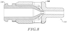
FIGURE 8 is a schematic illustration in cross-sectional view of an alternative jet pump assembly for use in the liquid trap assembly ofFigure 1 . -
FIGURE 9 is a schematic illustration of the liquid trap assembly ofFigure 1 mounted in a fuel tank and part of a vehicle fuel system. -
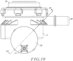
FIGURE 10 is a schematic illustration in end view of the liquid trap assembly ofFigure 1 . -
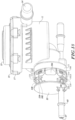
FIGURE 11 is a schematic illustration in cross-sectional view of the liquid trap assembly taken at lines 11-11 inFigure 10 and showing a housing connected to an end cap. -
FIGURE 12 is a close-up fragmentary cross-sectional view of an extension of the housing trapped in a recess of the end cap under a first operating condition. -
FIGURE 13 is a close-up fragmentary cross-sectional view of the extension of the housing trapped in the recess of the end cap under a second operating condition. -
FIGURE 14 is a close-up fragmentary cross-sectional view of the extension of the housing trapped in the recess of the end cap under a third operating condition. -
FIGURE 15 is a close-up fragmentary cross-sectional view of an alternate extension for the housing shown trapped in the recess of the end cap under the first operating condition. -
FIGURE 16 is a close-up fragmentary cross-sectional view of the alternate extension of the housing trapped in the recess of the end cap under the second operating condition. -
FIGURE 17 is a close-up fragmentary cross-sectional view of the alternate extension of the housing trapped in the recess of the end cap under the third operating condition. -
FIGURE 18 is a schematic illustration in exploded perspective view of the liquid trap assembly ofFigure 2 . - Referring to the drawings, wherein like reference numbers refer to like components throughout the several views,
Figure 1 shows aliquid trap assembly 10 that efficiently drains liquid collected from vapor. Theliquid trap assembly 10 can also be referred to as an active liquid drain. Theliquid trap assembly 10 has ahousing 12. Thehousing 12 has a first port, referred to as a vapor flow inlet 14 (shown inFigure 2 ) and a second port, referred to as avapor flow outlet 16 in fluid communication with aninterior cavity 18 formed at least in part by thehousing 12. As shown inFigure 2 , theoutlet 16 is formed by anupper cap 13 secured to thehousing 12 withtabs 15 fit throughtab retainers 17. Vapor flows from thevapor flow inlet 14, through thecavity 18, to thevapor flow outlet 16. Liquid entrained in the vapor flow is collected in aliquid trap 20 formed by thehousing 12 at the bottom of thehousing 12. Afilter 19 extends across the lowest portion of thetrap 20. Theoutlet 16 can be replaced by an outlet valve, or thehousing 12 can have no outlet. - An
end cap 23 is connected to thehousing 12 in a manner described herein. Thehousing 12 can be a one-piece, molded plastic component. Theend cap 23 can also be a one-piece, molded plastic component. Either or both of thehousing 12 and anend cap 23 described can have features that promote separation of liquid and vapor, such as baffles and ribs. As used herein, theend cap 23 is referred to as a first component of theliquid trap assembly 10, and thehousing 12 is referred to as a second component of theliquid trap assembly 10. - The
liquid trap assembly 10 can be used in many applications. In one application described herein, theliquid trap assembly 10 is used in a fuel vapor recovery system 21 on a vehicle, shown schematically inFigure 9 . The vehicle can be a diesel, gasoline, or hybrid application. Vapor is vented from afuel tank 22 that containsliquid fuel 93. The vapor is vented through avapor vent valve 26 that may provide pressure relief, rollover shutoff, and other functions. Vapor flows from thevapor vent valve 26 to theliquid trap assembly 10 through theinlet 14 and exits through theoutlet 16 to a vapor recovery device, such as a canister (C) 28 filled with carbon granules. Thecanister 28 is periodically purged to an engine (E) 30. Theliquid trap assembly 10 is shown mounted within thefuel tank 22. Alternatively, theliquid trap assembly 10 can be external to thefuel tank 22. - Referring to
Figure 1 , thehousing 12 forms afirst opening 35 in a sidewall adjacent to theliquid trap 20. The opening 35 is selectively closed by acheck valve 36. Any type of valve can be used to close theopening 35, or there can be no valve at the opening 35. Thecheck valve 36 includes avalve body 38 and aspring 40 that biases thevalve body 38 into thefirst opening 35 to close theopening 35 and separate thecavity 18 andliquid trap 20 from avalve cavity 42 in which thespring 40 andvalve body 38 are movable, as described herein. When thecheck valve 36 closes theopening 35, it also prevents liquid from entering or exiting theliquid trap 20 through the opening 35. Thevalve body 38 is generally annular and has a generally cone-shaped end that extends into thecavity 18. Thespring 40 has a diameter that fits inside the generallyannular valve body 38. A valve body with a different shape can also be used. For example, a ball valve may be used to close theopening 35. - The
liquid trap assembly 10 includes ajet pump assembly 44. Thejet pump assembly 44 includes anozzle carrier 46 and aventuri nozzle 48. Thenozzle carrier 46 has anentrance port 50 that extends through a generally annularouter wall 55 of thenozzle carrier 46 in operative fluid communication with theliquid trap 20, as best shown inFigure 1 . That is, alower extent 53 of thecavity 42 is in communication with theentrance port 50. When thevalve 36 opens, thespring 40 depresses, and thevalve body 38 will move past the lower extent 53 (to the left inFigure 1 ) so that theliquid trap 20 empties to thelower extent 53 and through theentrance port 50 into a longitudinal passage 52 (shown inFigure 3 ) of thenozzle carrier 46. Thelongitudinal passage 52 extends completely through thenozzle carrier 46 as best shown inFigures 3 and7 , and is larger in thecarrier portion 54 than in thediffuser portion 58. Thelongitudinal passage 52 is in fluid communication with theentrance port 50. Thevalve 36 is configured to prevent draining of theliquid trap 20 by thejet pump assembly 44 when a pressure differential created by liquid flow through theventuri nozzle 48 is below a predetermined level, and to allow fluid communication between thejet pump assembly 44 and theliquid trap 20 when the pressure differential is above the predetermined level. It should be appreciated, however, that thevalve 36 is optional, and thejet pump assembly 44 could drain theliquid trap 20 sufficiently if novalve 36 was present. - Flow through the
venturi nozzle 48 induces draining of theliquid trap 20. As shown inFigure 9 , thejet pump assembly 44 is connected bytubing 90, 94 to afuel pump 92 submerged in theliquid fuel 93. Thefuel pump 92 is also connected to theengine 30 viafuel discharge tubing 94. Fuel is discharged from thefuel pump 92 at relatively high pressure through thefuel discharge tubing 94. The tubing 90 branches from thefuel discharge tubing 94, providing relatively high pressure liquid fuel flow to aninlet portion 63 of thehousing 12 that is in fluid communication with aninlet 64 of thenozzle 48 indicated inFigure 3 . - Referring again to
Figure 1 , fluid flowing out of thenozzle 48 creates a vacuum or at least a relatively low pressure area in thelongitudinal passage 52 adjacent theentrance port 50. Pressure is also reduced in thecavity 42 due to the vacuum or low pressure in thelongitudinal passage 52, creating a pressure differential across thevalve body 36, as pressure in thecavity 42 is lower than pressure in thecavity 18. When the pressure differential reaches a predetermined level such that a force created by the pressure differential on the area of thevalve body 38 exposed to thecavity 18 is greater than the force keeping thecheck valve 36 shut (in this case the force of the spring 40), thevalve body 38 will move toward theend cap 23, compressing thespring 40 and establishing fluid communication between theliquid trap 20 and theentrance port 50. Thejet pump assembly 44 is a fuel discharge assembly that has the propelling mechanism, due to the pressure differential and jet action through thenozzle 48, to discharge liquid fuel in thetrap 20 to thefuel tank 22. - The
jet pump assembly 44 utilizes high pressure fluid from thefuel pump 92 which flows through thenozzle 48 with a high velocity. The flow through thenozzle 48 is referred to as the primary flow or primary stream. The high velocity fluid leaving thenozzle 48 creates a low pressure or a vacuum in the area adjacent thenozzle 48, such as at theentrance port 50. The pressure differential between the high pressure fluid exiting thenozzle 48 and thelower extent 53 of thecavity 42 adjacent thenozzle 48 induces flow, such as through theentrance port 50, referred to as an induced stream or secondary flow. - Referring to
Figure 1 , thejet pump assembly 44 has anoptional pressure reducer 61 located in thepassage 57 formed by theinlet portion 63 of thehousing 12, upstream of theinlet 64 and thenozzle 48. Thepressure reducer 61 can instead be located further upstream of thejet pump assembly 44 such as in a vent line leading to thejet pump assembly 44. Thepressure reducer 61 reduces pressure and volume flow rate of fluid flow through theinlet portion 63 to thenozzle 48, while increasing velocity of flow through thenozzle 48. - A
diffuser portion 58 of thenozzle carrier 46 is shown inFigure 3 supported by thehousing 12. Thelongitudinal passage 52 in thediffuser portion 58 is in fluid communication with adiffuser passage 59 formed by anoutlet 65 of the housing 12 (best shown inFigure 1 ) to increase pressure and reduce velocity of the fluid. Many factors affect the performance and efficiency of thejet pump assembly 44, including fluid molecular weight, feed temperature, position of thenozzle 48, throat dimension, motive velocity, Reynolds number, pressure ratio, specific heat ratio, and the angle between the motive and induced stream. - The
nozzle carrier 46 also has acarrier portion 54 extending from afirst end 56 of thenozzle carrier 46 to theentrance port 50. Thediffuser portion 58 of thenozzle carrier 46 extends from theentrance port 50 to asecond end 60 of thenozzle carrier 46 opposite thefirst end 56.Figures 4 and 7 show that there are severaladditional ports nozzle carrier 46, and are spaced angularly about thenozzle carrier 46 in the vicinity of theentrance port 50. Afourth entrance port 50A isopposite port 50C and betweenports 50 and 50B. Afilter 51 shown inFigure 3 surrounds thenozzle carrier 46 at theport 50 to screen liquid entering theport 50 from thetrap 20. Thenozzle carrier 46 has a longitudinal center axis A1. - The
venturi nozzle 48 has abody portion 62 with aninlet 64, and anozzle portion 66 with anozzle tip 68 forming anoutlet 70. Thenozzle 48 also has a longitudinal center axis A2. Thenozzle carrier 46 and theventuri nozzle 48 are configured so that thebody portion 62 fits to thecarrier portion 54 in thelongitudinal passage 52, with thenozzle portion 66 extending past theentrance port 50 so that thenozzle tip 68 is directed into thediffuser portion 58. The fit of thebody portion 62 to thecarrier portion 54 is a press-fit. As shown inFigure 5 , thenozzle carrier 46 has spaced, radially-inwardly extendingridges 47 extending into thelongitudinal passage 52 so that thebody portion 62 of theventuri nozzle 48 is fit to thecarrier portion 54 of thenozzle carrier 46 at theridges 47. - The
nozzle 48 is inserted into thelongitudinal passage 52 from thefirst end 56 until a first steppedshoulder 72 of thebody portion 62 abuts anouter wall 55 of thenozzle carrier 46 at thefirst end 56. In this position, a predetermined clearance 71 exists between thetip 68 and the inner wall of thediffuser portion 58 defining thepassage 52. - Alignment of the longitudinal axis A2 of the
venturi nozzle 48 with the longitudinal axis A1 of thenozzle carrier 46 is dependent only on thenozzle carrier 46 and theventuri nozzle 48 when theventuri nozzle 48 is fit to thenozzle carrier 46 in this manner. More specifically, all other surrounding components that support thejet pump assembly 44 are configured to have larger radial clearances between thejet pump assembly 44 and the components than aclearance 67 of the tight press-fit of thebody portion 62 of thenozzle 48 to thecarrier portion 54 of thenozzle carrier 46. The axes A1, A2 remain substantially aligned under all operating conditions due to the controlledclearance 67. For example, inFigure 3 , thecarrier portion 54 is supported by theend cap 23 in a first cylindrical cavity 74 of theend cap 23. A first clearance 76 between theend cap 23 and thecarrier portion 54 is much larger than the press-fit clearance 67 of thenozzle body portion 62 to thecarrier portion 54. Aclearance 73 between a first stepped portion 75 of thenozzle 48 and acylindrical extension 77 of theend cap 23 is also larger than theclearance 67 of thenozzle 48 to thenozzle carrier 46. Finally, asecond shoulder 79 of thenozzle 48 flares outward to form asecond shoulder portion 81. Aclearance 83 between thesecond shoulder portion 81 and theend cap 23 in the cavity 74 is larger than the press-fit clearance 67 of thenozzle 48 to thenozzle carrier 46. Aresilient ring 85 stabilizes thesecond shoulder portion 81 on theextension 77. A resilient O-ring seal 87 stabilizes the first shoulder portion 75 on theextension 77. - The
diffuser portion 58 of thenozzle carrier 46 is press-fit to thehousing 12 in a cylindrical cavity 78 of thehousing 12 along only a small press-fit portion 80 of an exterior surface 84 of thediffuser portion 58. In other words, the radial clearance 82 between thediffuser portion 58 and thehousing 12 at the cavity 78 is greater in all other areas than at the press-fit portion 80. Thenozzle 48 can be a machined, deep drawn metal in order to ensure the precise press-fit clearance 67 of thenozzle 48 to thenozzle carrier 46. Thenozzle carrier 46 can be a plastic injection-molded component such as a glass-filled polyoxymethylene plastic (POM) or similar grade with a predetermined low fuel-swell performance in the presence of automotive fuel. - In an alternative embodiment of a
jet pump assembly 144 shown inFigure 8 , thenozzle carrier 146 can be machined, deep drawn metal, and thenozzle 148 can be a plastic injection molded component such as a glass-filled POM or similar grade plastic with a predetermined low fuel-swell performance in the presence of automotive fuel. In still other embodiments, both the nozzle and the nozzle carrier can be a deep drawn metal, or both can be injection-molded plastic components. - The components of the
jet pump assembly 44, theend cap 23, and thehousing 12 are configured so that theclearances radial clearances nozzle 48 to thenozzle carrier 46. The assemblednozzle 48 andnozzle carrier 46 will be able to move radially as a unit relative to theend cap 23 and thehousing 12, and to rotate as a unit relative to theend cap 23 and thehousing 12 about the aligned longitudinal center axes A1, A2 without affecting the alignment of the longitudinal axis A1 of thenozzle carrier 46 with the longitudinal axis A2 of thenozzle 48. If the entirejet pump assembly 44 rotates as a unit, theadditional ports 50A, 50B, etc. will allow liquid to drain into thelongitudinal passage 52 as one will be in communication with thelower extent 53 regardless of the position of theport 50 relative to thelower extent 53. - In order for the the
nozzle 48 to remain sufficiently axially aligned with thenozzle carrier 46 throughout the range of operating conditions, a constant axial compressive force should be maintained in thejet pump assembly 44. Accordingly, theliquid trap assembly 10 provides a constant tension snap-fit between a first component (i.e., the end cap 23) and a second component (i.e., the housing 12) to create a constant axial compressive force on additional components, such as a thenozzle 48 and thenozzle carrier 46, supported by and between the first and second components to prevent relative axial movement of thenozzle 48 and thenozzle carrier 46. As best shown inFigures 2 and18 , theend cap 23 has a firstouter surface 1 00 and a plurality of spacedextensions outer surface 100. The firstouter surface 100 is generally cylindrical. - The
housing 12 has aflexible rim 104 surrounding and partially defining a cavity 105, indicated inFigure 1 . Thecavity 1 05 is configured to contain a portion of theend cap 23 when theend cap 23 is partially inserted into the cavity 105, and to contain thecavity 42 withspring 40 andcheck valve 36. Theflexible rim 104 is generally cylindrical and is configured to surround the firstouter surface 100 when theend cap 23 is fit partially within the cavity 105. Theflexible rim 104 is shown withdiscrete flap portions 106 inFigure 2 , but could instead be continuous and unsectioned. - The
flexible rim 104 has spacedrecesses 108 that have a spacing substantially equal to the spacing of theextensions rim 104 flexes to surround theend cap 23 and trap theextensions 102 in therecesses 108. Although flexible, therim 104 remains biased toward an unflexed state when in the flexed state shown inFigure 2 . The unflexed state is the position of therim 104 when theend cap 23 is removed from the cavity 105. In the unflexed state, the effective diameter of therim 104 will be less than in the flexed state. In other words, theflexible rim 104 is configured with a material, such as a plastic, that has sufficient stiffness to return to a pre-stressed or unflexed state when an object or force causing the flexed state is removed. When flexed, theflexible rim 104 provides a constant radially-inward force F (i.e., a force toward the center axis A3 of the flexible rim 104) as shown inFigure 2 . As shown inFigure 18 , some of theextensions 102A have acenter portion 109 that interrupts the angled surfaces and acts as an anti-rotation feature to prevent axial movement of theend cap 23 relative to thehousing 12. Theend cap 23 and thehousing 12 can be the same material or a different material, such as the same or different types of plastic that can swell and shrink in the presence of fuel or other medium over the range of operating conditions. - The
extensions flexible rim 104 are configured so that theextensions recesses 108 and will prevent therim 104 from returning to the unflexed state over a predetermined range of operating conditions experienced by theassembly 10 during use. As explained herein, the constant radially-inward force F of therim 104, illustrated at eachflap portion 106 ofFigure 2 , creates a force Fl at the interface of eachextension 102 with therim 104 that pulls thehousing 12 toward theend cap 23, and a reaction force F2 at the interface of eachextension rim 104 that pushes theend cap 23 toward thehousing 12. The forces F1, F2 are maintained over the predetermined range of operating conditions due to the bias of therim 104 toward the unflexed state. The force F1 and reaction force F2 are in opposite directions, and are parallel with a center axis A3 of theend cap 23 andflexible rim 104 shown inFigure 1 . The center axis A3 is in turn parallel with the aligned axes A1, A2 of thenozzle 48 andnozzle carrier 46. -
Figures 12-14 show the interface of one of theextensions 102 with theflexible rim 104 in greater detail, and are representative of the interface of each of theextensions rim 104. Theextension 102 shown is the lower extension ofFigure 11 but rotated in view to show theextension 102 generally upright. Theextension 102 has a base 110 with a first width W1 at theouter surface 1 00 of theend cap 23. The bottom of theextension 102 is thebase 1 10. Eachrecess 108 has a second width W2 narrower than the first width W1 to prevent the base 110 from fitting within therecess 108 under the predetermined range of operating conditions. In other words, thebase 110 is configured to be too wide to fit within therecess 108 under the entire range of operating conditions, including swelling of theend cap 23 andhousing 12 that can occur in the presence of fuel, and re-drying of theend cap 23 andhousing 12 after such swelling. As shown inFigure 12 , the position of therim 104 on theextension 102 is a nominal state representing operating conditions that are neither: (i) those causing a maximum swell of components; nor (ii) those causing a minimum size of the components, such as would occur without any swelling after a re-dry. - Each
extension angled surface 112 and a secondangled surface 114 that each extend from theouter surface 1 00 at opposite ends of thebase 110 and meet at aridge 116. The firstangled surface 112 has afirst portion 118 with a first incline relative to thebase 110, and asecond portion 120 with a second incline relative to thebase 110. Thefirst portion 118 extends from the base 110 to thesecond portion 120, and thesecond portion 120 extends from thefirst portion 118 to theridge 116. The second incline is steeper than the first incline. This is indicated inFigure 13 by a first angle of incline Θ1 of thefirst portion 118 being less than a second angle of incline Θ2 of thesecond portion 120. - The
extension 102 is configured so that anedge 122 of theflexible rim 104 at therecess 108 in which theextension 102 is retained rests along the firstangled surface 112 under the entire predetermined range of operating conditions. An overall axial dimension X shown inFigure 3 in which thenozzle carrier 46 andnozzle 48 are constrained changes as thenozzle carrier 46,end cap 23, andhousing 12 swell due to fuel exposure and shrink due to re-drying after exposure to fuel or other medium. Both the relative axial dimensions of these components as well as the clearances between the components change. For example,Figure 13 represents the relative positions of theextension 102 and theflexible rim 104 whennozzle carrier 46,end cap 23, andhousing 12 shrink due to re-drying after exposure to fuel or other medium.Figure 13 represents the minimum sizes of these components under these predetermined operating conditions. In that instance, because the axial dimension X is likely to shrink, theextensions recesses 108, there will be less tension between theflexible rim 104 and theextensions edge 122 of therim 104 will rest closer to thebase 110 along thesurface 118 than under the first predetermined operating condition ofFigure 12 . Even under this operating condition, however, therim 104 is prevented from returning to an unflexed state, and some force F1 and reaction force F2 is maintained, also acting on thenozzle carrier 46 andnozzle 48 to keep these components form relative axial movement. That is, the forces F1, F2 also act at thesecond end 60 of thenozzle carrier 46 and thehousing 12, and at the steppedshoulder 72 and thenozzle 48, as shown inFigure 3 . -
Figure 14 represents the relative positions of theextension 102 and theflexible rim 104 when thenozzle carrier 46,end cap 23, andhousing 12 swell due to exposure to fuel or other medium.Figure 14 represents the maximum sizes of these components under all of the operating conditions. In that instance, because the axial dimension X is likely to be larger, theextensions recesses 108, there will be greater tension between theflexible rim 104 and theextensions edge 122 of therim 104 will rest further from thebase 110 along thesurface 120. Therim 104 is prevented from returning to an unflexed state, and a force F1 and reaction force F2 is maintained, also acting on thenozzle carrier 46 andnozzle 48 to keep these components from relative axial movement. -
Figures 15-17 show analternate extension 202 that can be used with other like spaced extensions on theend cap 23 to interface with theflexible rim 104 in a manner that will provide a constant tension and resultant axial force on thenozzle carrier 46 andnozzle 48 under the predetermined range of operating conditions. Theextension 202 has a firstangled surface 212 and a secondangled surface 214 both extending from abase 210 and meeting at atridge 216. Unlike theextension 102, the firstangled surface 212 does not have different portions with different angles of incline relative to thebase 110. -
Figure 15 shows therim 104 andextension 202 in a nominal state in which theedge 122 of therim 104 at therecess 108 interfaces with the firstangled surface 212. Therim 104 is prevented from returning to an unflexed state, and some force F1 and reaction force F2 is maintained at eachextension 202, also acting on thenozzle carrier 46 andnozzle 48 to keep these components from relative axial movement. -
Figure 16 represents the relative positions of theextension 202 and theflexible rim 104 when thenozzle carrier 46,end cap 23, andhousing 12 shrink due to re-drying after exposure to fuel or other medium.Figure 16 represents the minimum sizes of these components under all of the operating conditions. In that instance, because the axial dimension X ofFigure 3 is likely to be smaller, theextensions 202 will be axially closer to therecesses 108, there will be less tension between theflexible rim 104 and theextensions 202, and theedge 122 of therim 104 will rest closer to thebase 210 along thesurface 212. Even under this operating condition, therim 104 is prevented from returning to an unflexed state, and a force F1 and reaction force F2 are maintained, also acting on thenozzle carrier 46 andnozzle 48 to keep these components from relative axial movement. -
Figure 17 represents the relative positions of theextension 202 and theflexible rim 104 when thenozzle carrier 46,end cap 23, andhousing 12 swell due to exposure to fuel or other medium.Figure 17 represents the maximum sizes of these components under all of the operating conditions. In that instance, because the axial dimension X ofFigure 3 is likely to be larger, theextensions 202 will be axially further from therecesses 108, there will be greater tension between theflexible rim 104 and theextensions 202, and theedge 122 of therim 104 will rest further from thebase 210 along thesurface 212. Therim 104 is prevented from returning to an unflexed state, and a force F1 and reaction force F2 are maintained, also acting on thenozzle carrier 46 andnozzle 48 to keep these components from relative axial movement. - The constant tension snap-fit ability of the
extensions - The reference numbers used in the drawings and the specification along with the corresponding components are as follows:
- 10
- liquid trap assembly
- 12
- housing/second component
- 13
- upper cap
- 14
- first port/vapor flow inlet
- 15
- tab
- 16
- second port/vapor flow outlet
- 17
- tab retainer
- 18
- interior cavity
- 19
- filter
- 20
- liquid trap
- 21
- fuel vapor recovery system
- 22
- fuel tank
- 23
- end cap/first component
- 26
- vapor vent valve
- 28
- canister (C)
- 30
- engine (E)
- 35
- first opening of
housing 12 - 36
- check valve
- 38
- valve body
- 40
- spring
- 42
- valve cavity
- 44
- jet pump assembly
- 46
- nozzle carrier
- 47
- ridges
- 48
- venturi nozzle
- 50
- entrance port
- 50A
- entrance port
- 50B
- entrance port
- 50C
- entrance port
- 51
- filter
- 52
- longitudinal passage of nozzle carrier
- 53
- lower extent of
cavity 42 - 54
- carrier portion
- 55
- wall
- 56
- first end of
nozzle carrier 46 - 57
- passage
- 58
- diffuser portion
- 59
- diffuser passage
- 60
- second end of
nozzle carrier 46 - 61
- reducer
- 62
- body portion of
nozzle 48 - 63
- inlet portion of
housing 12 - 64
- inlet of
nozzle 48 - 65
- outlet of
housing 12 - 66
- nozzle portion
- 67
- clearance of
nozzle 48 tocarrier portion 54 - 68
- nozzle tip
- 70
- outlet of
nozzle 48 - 71
- predetermined clearance
- 72
- first stepped shoulder of body portion
- 73
- clearance first stepped portion 75 and
cylindrical extension 77 - 74
- first cylindrical cavity of end cap
- 75
- first stepped portion of
nozzle 48 - 76
- first clearance of
end cap 23 tocarrier portion 54 - 77
- cylindrical extension of end cap
- 78
- cylindrical cavity of
housing 12 - 79
- second shoulder of
nozzle 48 - 80
- press-fit portion
- 81
- second shoulder portion
- 82
- radial clearance of
diffuser portion 58 andhousing 12 - 83
- clearance
second shoulder portion 81 to endcap 23 - 84
- exterior surface of
diffuser portion 58 - 85
- resilient ring
- 87
- O-ring seal
- 90
- tubing
- 92
- fuel pump (P)
- 93
- liquid fuel
- 94
- fuel discharge tubing
- 100
- first outer surface of
end cap 23 - 102
- extensions of
end cap 23 - 102A
- extensions of
end cap 23 - 104
- flexible rim of
housing 12 - 105
- cavity of
housing 12 - 1 06
- flap portions of rim
- 108
- recesses in rim
- 109
- center portion of
extension 102A - 110
- base of
extension 102 - 112
- first angled surface
- 114
- second angled surface
- 116
- ridge
- 118
- first portion of first angled surface
- 120
- second portion of second angled surface
- 122
- edge of
rim 104 - 146
- nozzle carrier
- 148
- nozzle
- 202
- extension
- 210
- base
- 212
- first angled surface
- 214
- second angled surface
- 216
- ridge
- A1
- longitudinal center axis of
nozzle carrier 48 - A2
- longitudinal center axis of
nozzle 48 - A3
- center axis of
rim 104 andend cap 13 - C
- canister
- E
- engine
- F
- force of rim
- F1
- force of
extension 102 onrim 104 - F2
- reaction force of rim on extension
- P
- pump
- X
- axial dimension
- W1
- first width of base
- W2
- width of recess
- Θ1
- first angle of incline
- Θ2
- second angle of incline
- While the best modes for carrying out the many aspects of the present teachings have been described in detail, those familiar with the art to which these teachings relate will recognize various alternative aspects for practicing the present teachings that are within the scope of the appended claims.
Claims (14)
- An assembly comprising:a first component (23) having a first outer surface (100) and a plurality of spaced extensions (202) extending outward from the first outer surface (100), wherein the first component (23) is an end cap; anda second component (12) having a flexible rim (104) surrounding a cavity (105), wherein the second component (12) is a vapor valve housing, the flexible rim (104) has spaced recesses (108), and the flexible rim (104) has a bias that biases the flexible rim (104) toward an unflexed state when in a flexed state;wherein the first component (23) is configured to fit at least partially into the cavity (105) with the flexible rim (104) flexing to surround the first component (23) and trap the plurality of spaced extensions (202) in the recesses (108); andwherein the plurality of spaced extensions (202) are configured to prevent the flexible rim (104) from returning to the unflexed state over a predetermined range of operating conditions, the bias of the flexible rim (104) thereby forcing the first component (23) toward the second component (12) over the predetermined range of operating conditions;characterized in that:each of the plurality of spaced extensions (202) has a base (210) with a first width at the first outer surface (100) of the first component (23);each of the recesses (108) has a second width narrower than or equal to the first width to prevent the bases (210) of the plurality of spaced extensions (202) from fitting within the recesses (108) under the predetermined range of operating conditions;each of the plurality of spaced extensions (202) has:a ridge (216); anda first angled surface (212) and a second angled surface (214) each extending from opposite ends of the base (210) and meeting at the ridge (216), wherein the first angled surface (212) has a constant angle of incline relative to the base (210); andwherein an edge (122) of the second component (12) at the recess (108) in which the extension (202) is trapped rests along the first angled surface (212) under the predetermined range of operating conditions.
- The assembly of claim 1, further comprising:additional components supported by the first component (23) and the second component (12) at least partially in the cavity (105); and wherein bias of the flexible rim (104) causes the first and second components (23, 12) to force the additional components toward one another;wherein the additional components include a jet pump nozzle (48) and a nozzle carrier (46) supporting the jet pump nozzle (48).
- The assembly of claim 2,
wherein the edge (122) of the second component (12) at the recess (108) interfaces with the first angled surface (212) in a manner that provides a constant tension and resultant axial force on the nozzle carrier (46) and the nozzle (48) to keep the nozzle carrier (46) and the nozzle (48) from relative axial movement. - The assembly of claim 2,wherein a shoulder (72) of the jet pump nozzle (48) is positioned axially between the end cap (23) and one end (56) of the nozzle carrier (46); andwherein the nozzle carrier (46) is supported by both the end cap (23) and the housing (12).
- The assembly of claim 2, wherein:a first clearance (76) is defined between the nozzle carrier (46) and the end cap (23) under a predetermined range of operating conditions; andwherein the nozzle carrier (46) and the housing (12) are configured to have a press-fit along only a portion of an exterior surface of the nozzle carrier (46) under the predetermined range of operating conditions; the nozzle carrier (46) and the nozzle (48) thereby being movable as a unit relative to the end cap (23) and the housing (12) within the clearance (76) without affecting an alignment of a longitudinal axis of the nozzle carrier (A1) with a longitudinal axis of the nozzle (A2).
- The assembly of claim 1, wherein the plurality of spaced extensions (202) are configured to prevent the flexible rim (104) from returning to the unflexed state over a predetermined range of operating conditions to thereby maintain a force (F1) pushing the first component (23) toward the second component (12) and a reaction force (F2) pulling the second component (12) toward the first component (23) over the predetermined range of operating conditions.
- The assembly of claim 6, wherein the force (F1) and the reaction force (F2) are due to the bias of the flexible rim (104) toward the unflexed state.
- The assembly of claim 6, wherein the first outer surface and the flexible rim (100, 104) define a center axis (A3), and wherein the force (F1) and the reaction force (F2) are in opposite directions that are parallel with the center axis (A3).
- The assembly of claim 1, wherein at least one of the first component (23) and the second component (12) are of a material that swells over the predetermined range of operating conditions when the material is exposed to fuel or other medium.
- The assembly of claim 9, wherein a tension between the flexible rim (104) and the plurality of spaced extensions (202) increases when the first component (23) and the second component (12) swell.
- The assembly of claim 9, wherein the edge (122) of the second component (12) rests further from the base (210) along the first angled surface (212) when the first component (23) and the second component (12) swell.
- The assembly of claim 1, wherein at least one of the first component (23) and the second component (12) are of a material that shrinks over the predetermined range of operating conditions when the material is dried after exposure to fuel or other medium.
- The assembly of claim 12, wherein a tension between the rim (104) and the extensions (202) decreases when the first component (23) and the second component (12) shrink.
- The assembly of claim 12, wherein the edge (122) of the second component (12) rests closer to the base (210) along the first angled surface (212) when the first component (23) and the second component (12) shrink.
Applications Claiming Priority (5)
| Application Number | Priority Date | Filing Date | Title |
|---|---|---|---|
| US201361760022P | 2013-02-01 | 2013-02-01 | |
| US201361760023P | 2013-02-01 | 2013-02-01 | |
| US201361807461P | 2013-04-02 | 2013-04-02 | |
| PCT/US2013/043294 WO2014120261A1 (en) | 2013-02-01 | 2013-05-30 | Constant tension snap-fit assembly |
| EP13733106.2A EP2951475B1 (en) | 2013-02-01 | 2013-05-30 | Constant tension snap-fit assembly |
Related Parent Applications (2)
| Application Number | Title | Priority Date | Filing Date |
|---|---|---|---|
| EP13733106.2A Division-Into EP2951475B1 (en) | 2013-02-01 | 2013-05-30 | Constant tension snap-fit assembly |
| EP13733106.2A Division EP2951475B1 (en) | 2013-02-01 | 2013-05-30 | Constant tension snap-fit assembly |
Publications (2)
| Publication Number | Publication Date |
|---|---|
| EP4509343A2 true EP4509343A2 (en) | 2025-02-19 |
| EP4509343A3 EP4509343A3 (en) | 2025-05-14 |
Family
ID=48741478
Family Applications (3)
| Application Number | Title | Priority Date | Filing Date |
|---|---|---|---|
| EP13733105.4A Active EP2951474B1 (en) | 2013-02-01 | 2013-05-30 | Self-aligning jet pump assembly |
| EP25150079.9A Pending EP4509343A3 (en) | 2013-02-01 | 2013-05-30 | Constant tension snap-fit assembly |
| EP13733106.2A Active EP2951475B1 (en) | 2013-02-01 | 2013-05-30 | Constant tension snap-fit assembly |
Family Applications Before (1)
| Application Number | Title | Priority Date | Filing Date |
|---|---|---|---|
| EP13733105.4A Active EP2951474B1 (en) | 2013-02-01 | 2013-05-30 | Self-aligning jet pump assembly |
Family Applications After (1)
| Application Number | Title | Priority Date | Filing Date |
|---|---|---|---|
| EP13733106.2A Active EP2951475B1 (en) | 2013-02-01 | 2013-05-30 | Constant tension snap-fit assembly |
Country Status (3)
| Country | Link |
|---|---|
| EP (3) | EP2951474B1 (en) |
| CN (2) | CN105121925B (en) |
| WO (2) | WO2014120261A1 (en) |
Families Citing this family (3)
| Publication number | Priority date | Publication date | Assignee | Title |
|---|---|---|---|---|
| DE102016209204A1 (en) * | 2016-05-27 | 2017-11-30 | Robert Bosch Gmbh | Device for controlling at least one fluid flow in a vehicle |
| CN107542570B (en) * | 2016-06-27 | 2021-09-10 | 舍弗勒技术股份两合公司 | Thermal management module |
| US11767813B2 (en) | 2022-01-07 | 2023-09-26 | Delphi Technologies Ip Limited | Noise attenuating fuel trap for evaporative emission control canister system |
Family Cites Families (12)
| Publication number | Priority date | Publication date | Assignee | Title |
|---|---|---|---|---|
| US4505646A (en) * | 1982-11-15 | 1985-03-19 | Diversey Wyandotte Corporation | Eductor pump and process |
| US5413477A (en) * | 1992-10-16 | 1995-05-09 | Gas Research Institute | Staged air, low NOX burner with internal recuperative flue gas recirculation |
| US5372190A (en) * | 1993-06-08 | 1994-12-13 | Coleman; William P. | Down hole jet pump |
| US5458467A (en) * | 1994-01-14 | 1995-10-17 | Mcneil (Ohio) Corporation | Jet pump and method of operation thereof |
| US6634341B2 (en) * | 1999-04-28 | 2003-10-21 | Walbro Corporation | Vent and rollover valve and fuel pump module |
| US7546925B1 (en) * | 2000-12-04 | 2009-06-16 | Roush Life Sciences, Llc | Disposable vacuum filtration apparatus capable of detecting microorganisms and particulates in liquid samples |
| JP3929809B2 (en) * | 2002-04-03 | 2007-06-13 | 愛三工業株式会社 | Reserve container unit |
| EP1518739A3 (en) * | 2003-09-29 | 2005-11-30 | Alfmeier Präzision Ag Baugruppen und Systemlösungen | Vehicle tank including a venting system |
| US6918405B2 (en) * | 2003-12-04 | 2005-07-19 | Alfmeier Corporation | Fill limit vent valve |
| CN1255223C (en) * | 2003-12-19 | 2006-05-10 | 沈阳仪表科学研究院 | Long target-distance nozzle for high pressure washing |
| CN100342187C (en) * | 2005-12-01 | 2007-10-10 | 上海交通大学 | Two-phase flow injector replacing refrigerator throttling element |
| EP2715253B1 (en) * | 2011-05-23 | 2019-11-06 | Carrier Corporation | Ejectors and methods of manufacture |
-
2013
- 2013-05-30 WO PCT/US2013/043294 patent/WO2014120261A1/en not_active Ceased
- 2013-05-30 EP EP13733105.4A patent/EP2951474B1/en active Active
- 2013-05-30 WO PCT/US2013/043288 patent/WO2014120260A1/en not_active Ceased
- 2013-05-30 EP EP25150079.9A patent/EP4509343A3/en active Pending
- 2013-05-30 EP EP13733106.2A patent/EP2951475B1/en active Active
- 2013-05-30 CN CN201380075260.9A patent/CN105121925B/en active Active
- 2013-05-30 CN CN201380075275.5A patent/CN105121926B/en active Active
Also Published As
| Publication number | Publication date |
|---|---|
| CN105121926A (en) | 2015-12-02 |
| EP2951474B1 (en) | 2021-03-17 |
| CN105121925B (en) | 2018-01-02 |
| WO2014120260A1 (en) | 2014-08-07 |
| WO2014120261A1 (en) | 2014-08-07 |
| CN105121925A (en) | 2015-12-02 |
| EP2951475B1 (en) | 2025-02-12 |
| EP4509343A3 (en) | 2025-05-14 |
| CN105121926B (en) | 2018-01-02 |
| EP2951474A1 (en) | 2015-12-09 |
| EP2951475A1 (en) | 2015-12-09 |
Similar Documents
| Publication | Publication Date | Title |
|---|---|---|
| US9765735B2 (en) | Liquid trap with integral jet pump | |
| KR101638652B1 (en) | Anti-siphon device | |
| US20190178263A1 (en) | Constant tension snap-fit assembly | |
| US6634341B2 (en) | Vent and rollover valve and fuel pump module | |
| US20130133765A1 (en) | Fuel pump assembly | |
| KR101862958B1 (en) | Flap valve device and gas-liquid separating device comprising flap valve device | |
| US6877525B2 (en) | Check valve for fuel pump | |
| EP2951475B1 (en) | Constant tension snap-fit assembly | |
| CN109312699B (en) | Liquid and Vapor Separator | |
| US20070062493A1 (en) | Fuel supply module | |
| EP1767392A1 (en) | Check valve and method of making same | |
| KR102692353B1 (en) | Valve structure for preventing siphon | |
| CN112996999B (en) | Fuel pump assembly with electric motor fuel pump and fluid driven fuel pump | |
| CN113454327B (en) | Flow restrictors for fuel shut-off valves | |
| US12421924B2 (en) | Fuel supply assembly with in-tank reservoir |
Legal Events
| Date | Code | Title | Description |
|---|---|---|---|
| PUAI | Public reference made under article 153(3) epc to a published international application that has entered the european phase |
Free format text: ORIGINAL CODE: 0009012 |
|
| STAA | Information on the status of an ep patent application or granted ep patent |
Free format text: STATUS: THE APPLICATION HAS BEEN PUBLISHED |
|
| AC | Divisional application: reference to earlier application |
Ref document number: 2951475 Country of ref document: EP Kind code of ref document: P |
|
| AK | Designated contracting states |
Kind code of ref document: A2 Designated state(s): AL AT BE BG CH CY CZ DE DK EE ES FI FR GB GR HR HU IE IS IT LI LT LU LV MC MK MT NL NO PL PT RO RS SE SI SK SM TR |
|
| REG | Reference to a national code |
Ref country code: DE Ref legal event code: R079 Free format text: PREVIOUS MAIN CLASS: B60K0015035000 Ipc: F02M0037020000 |
|
| PUAL | Search report despatched |
Free format text: ORIGINAL CODE: 0009013 |
|
| AK | Designated contracting states |
Kind code of ref document: A3 Designated state(s): AL AT BE BG CH CY CZ DE DK EE ES FI FR GB GR HR HU IE IS IT LI LT LU LV MC MK MT NL NO PL PT RO RS SE SI SK SM TR |
|
| RIC1 | Information provided on ipc code assigned before grant |
Ipc: B60K 15/035 20060101ALN20250407BHEP Ipc: F02M 25/08 20060101ALI20250407BHEP Ipc: F04F 5/46 20060101ALI20250407BHEP Ipc: F16K 17/04 20060101ALI20250407BHEP Ipc: F02M 37/02 20060101AFI20250407BHEP |
|
| STAA | Information on the status of an ep patent application or granted ep patent |
Free format text: STATUS: REQUEST FOR EXAMINATION WAS MADE |
|
| 17P | Request for examination filed |
Effective date: 20251021 |