EP4509266A1 - Impact power tool and impact mechanism - Google Patents
Impact power tool and impact mechanism Download PDFInfo
- Publication number
- EP4509266A1 EP4509266A1 EP24191590.9A EP24191590A EP4509266A1 EP 4509266 A1 EP4509266 A1 EP 4509266A1 EP 24191590 A EP24191590 A EP 24191590A EP 4509266 A1 EP4509266 A1 EP 4509266A1
- Authority
- EP
- European Patent Office
- Prior art keywords
- cam
- hammer
- anvil
- shaft
- cam groove
- Prior art date
- Legal status (The legal status is an assumption and is not a legal conclusion. Google has not performed a legal analysis and makes no representation as to the accuracy of the status listed.)
- Pending
Links
Images







Classifications
-
- B—PERFORMING OPERATIONS; TRANSPORTING
- B25—HAND TOOLS; PORTABLE POWER-DRIVEN TOOLS; MANIPULATORS
- B25B—TOOLS OR BENCH DEVICES NOT OTHERWISE PROVIDED FOR, FOR FASTENING, CONNECTING, DISENGAGING, OR HOLDING
- B25B21/00—Portable power-driven screw or nut setting or loosening tools; Attachments for drilling apparatus serving the same purpose
- B25B21/02—Portable power-driven screw or nut setting or loosening tools; Attachments for drilling apparatus serving the same purpose with means for imparting impact to screwdriver blade or nut socket
- B25B21/026—Impact clutches
-
- B—PERFORMING OPERATIONS; TRANSPORTING
- B25—HAND TOOLS; PORTABLE POWER-DRIVEN TOOLS; MANIPULATORS
- B25B—TOOLS OR BENCH DEVICES NOT OTHERWISE PROVIDED FOR, FOR FASTENING, CONNECTING, DISENGAGING, OR HOLDING
- B25B23/00—Details of, or accessories for, spanners, wrenches, screwdrivers
- B25B23/14—Arrangement of torque limiters or torque indicators in wrenches or screwdrivers
- B25B23/147—Arrangement of torque limiters or torque indicators in wrenches or screwdrivers specially adapted for electrically operated wrenches or screwdrivers
- B25B23/1475—Arrangement of torque limiters or torque indicators in wrenches or screwdrivers specially adapted for electrically operated wrenches or screwdrivers for impact wrenches or screwdrivers
-
- B—PERFORMING OPERATIONS; TRANSPORTING
- B25—HAND TOOLS; PORTABLE POWER-DRIVEN TOOLS; MANIPULATORS
- B25B—TOOLS OR BENCH DEVICES NOT OTHERWISE PROVIDED FOR, FOR FASTENING, CONNECTING, DISENGAGING, OR HOLDING
- B25B21/00—Portable power-driven screw or nut setting or loosening tools; Attachments for drilling apparatus serving the same purpose
- B25B21/02—Portable power-driven screw or nut setting or loosening tools; Attachments for drilling apparatus serving the same purpose with means for imparting impact to screwdriver blade or nut socket
Definitions
- This application relates to impact power tools, such as impact drivers or impact wrenches, and impact mechanisms for impact power tools.
- Impact power tools such as impact drivers and impact wrenches are commonly used for the installation and removal of threaded fasteners.
- An example of an impact power tool is described in U.S. Pat. App. Pub. No. 2019/0344411 .
- an impact tool in an aspect, includes a housing; a motor disposed in the housing; an output tool holder; a transmission configured to be driven by the motor; and an impact mechanism configured to be driven by the transmission and to transmit torque from the transmission to the output tool holder.
- the impact mechanism includes a cam shaft extending along an axis and configured to be rotatably driven by an output member of the transmission, the cam shaft defining a first angled or curved (e.g., V-shaped, U-shaped, parabolic) cam groove on an outer surface of the cam shaft; a cam ring received over the cam shaft and defining a second angled or curved (e.g., V-shaped, U-shaped, parabolic) cam groove on an inner surface of the cam ring and a third angled or curved (e.g., V-shaped, U-shaped, parabolic) cam groove on an outer surface of the cam ring; a hammer received over the cam ring and defining a fourth angled or curved (e.g
- the spring When torque on the output tool holder is less than or equal to a threshold amount, the spring maintains the cam ring and the hammer in their forwardmost position relative to the cam shaft so that the hammer projection engages the anvil projection and the cam shaft, the cam ring, the hammer, and the anvil rotate together as a unit about the axis.
- torque on the output tool holder increases to exceeds the threshold amount, the first ball moves along the first and second cam grooves so that the cam ring moves rotatably and axially rearward relative to the cam shaft, the second ball moves along the third and fourth cam grooves, so that the hammer moves rotatably and axially rearward relative to the cam ring, which decouples the hammer projections from the anvil projections.
- the spring drives the cam ring rotationally and axially forward relative to the cam shaft and the hammer rotationally and axially forward relative to the cam ring, such that the hammer projection rotationally strikes the anvil projection to impart a rotational impact to the anvil.
- a powered rotary impact tool in another aspect, includes a housing, a motor disposed in the housing, an output shaft, a transmission configured to be driven by the motor, and an impact mechanism configured to be driven by the transmission and to transmit torque from the transmission to the output tool holder.
- the impact mechanism includes a cam shaft extending along an axis and configured to be rotatably driven by an output member of the transmission, the cam shaft defining a first cam groove on an outer surface of the cam shaft.
- a cam ring is received over the cam shaft and defines a second cam groove on an inner surface of the cam ring and a third cam groove on an outer surface of the cam ring.
- a hammer is received over the cam ring and defines a fourth cam groove on an inner surface of the hammer and including a hammer projection on a front portion of the hammer.
- An anvil is coupled to the output shaft for rotation with the output shaft.
- the anvil has an anvil projection configured to be selectively engaged by the hammer projection.
- a first spring is configured to bias the hammer toward the anvil.
- a first ball is received in the first cam groove and the second cam groove and configured to couple the cam ring to the cam shaft for rotational and axial movement relative to the cam shaft.
- a second ball is received in the third cam groove and the fourth cam groove and configured to couple the hammer to the cam ring for rotational and axial movement relative to the cam ring.
- the first spring When torque on the output shaft is less than or equal to a threshold amount, the first spring maintains the hammer in its forwardmost position relative to the cam shaft so that the hammer projection engages the anvil projection, and the cam shaft, the cam ring, the hammer, and the anvil rotate together as a unit about the axis.
- the first ball moves along the first and second cam grooves so that the cam ring moves rotatably and axially rearward relative to the cam shaft, and the second ball moves along the third and fourth cam grooves, so that the hammer moves rotatably and axially rearward relative to the cam ring, which decouples the hammer projection from the anvil projection, and, when the first spring force and the torque of the motor overcomes the inertia of the hammer, the first spring drives the cam ring rotationally and axially forward relative to the cam shaft and the hammer rotationally and axially forward relative to the cam ring, such that the hammer projection rotationally strikes the anvil projection to impart a rotational impact to the anvil.
- the first cam groove and the second cam groove are angled or curved.
- the first cam groove is V-shaped with an open end of the first cam groove facing rearward away from the anvil.
- the second cam groove is V-shaped with an open end of the second cam groove facing forward toward the anvil.
- the third cam groove and the fourth cam groove are angled or curved.
- the third cam groove is V-shaped with an open end of the first cam groove facing rearward away from the anvil.
- the fourth cam groove is V-shaped with an open end of the second cam groove facing forward toward the anvil.
- the third cam groove is angularly offset from the first cam groove and the fourth cam groove is angularly offset from the second cam groove.
- the first spring is disposed between the transmission and the hammer.
- a second spring is disposed between the transmission and the cam ring.
- a powered rotary impact tool in another aspect, includes a cam shaft extending along an axis and configured to be rotatably driven upon actuation of the power tool.
- the cam shaft defines a first cam groove on an outer surface of the cam shaft.
- a cam ring is received over the cam shaft and defines a second cam groove on an inner surface of the cam ring and a third cam groove on an outer surface of the cam ring.
- a hammer is received over the cam ring and defines a fourth cam groove on an inner surface of the hammer and includes a hammer projection on a front portion of the hammer.
- An anvil includies an output shaft and an anvil projection configured to be selectively engaged by the hammer projection.
- a first spring is configured to bias the hammer toward the anvil.
- a first ball is received in the first cam groove and the second cam groove and configured to couple the cam ring to the cam shaft for rotational and axial movement relative to the cam shaft.
- a second ball is received in the third cam groove and the fourth cam groove and configured to couple the hammer to the cam ring for rotational and axial movement relative to the cam ring.
- the first ball moves along the first and second cam grooves so that the cam ring moves rotatably and axially rearward relative to the cam shaft, and the second ball moves along the third and fourth cam grooves, so that the hammer moves rotatably and axially rearward relative to the cam ring, which decouples the hammer projection from the anvil projection, and, when the first spring force and the torque of the motor overcomes the inertia of the hammer, the first spring drives the cam ring rotationally and axially forward relative to the cam shaft and the hammer rotationally and axially forward relative to the cam ring, such that the hammer projection rotationally strikes the anvil projection to impart a rotational impact to the anvil.
- the first cam groove and the second cam groove are angled or curved.
- the first cam groove is V-shaped with an open end of the first cam groove facing rearward away from the anvil.
- the second cam groove is V-shaped with an open end of the second cam groove facing forward toward the anvil.
- the third cam groove is V-shaped with an open end of the first cam groove facing rearward away from the anvil.
- the fourth cam groove is V-shaped with an open end of the second cam groove facing forward toward the anvil.
- the third cam groove is angularly offset from the first cam groove and the fourth cam groove is angularly offset from the second cam groove.
- the first spring is disposed between the transmission and the hammer.
- a second spring is disposed between the transmission and the cam ring.
- a powered rotary impact tool includes a housing, a motor disposed in the housing, an output shaft, a tool holder coupled to the output shaft for rotation with the output shaft, a transmission configured to be driven by the motor, and an impact mechanism configured to be driven by the transmission and to transmit torque from the transmission to the output tool holder.
- the impact mechanism includes a cam shaft extending along an axis and configured to be rotatably driven by an output member of the transmission, the cam shaft defining a first V-shaped cam groove on an outer surface of the cam shaft.
- a cam ring is received over the cam shaft and defines a second V-shaped cam groove on an inner surface of the cam ring facing an opposite direction from the first V-shaped cam groove, and a third V-shaped cam groove on an outer surface of the cam ring offset angularly from the first V-shaped cam groove.
- a hammer is received over the cam ring and defines a fourth V-shaped cam groove on an inner surface of the hammer facing an opposite direction from the third V-shaped cam groove and offset angularly from the second V-shaped cam groove, the hammer including a hammer projection on a front portion of the hammer.
- An anvil is coupled to the output shaft for rotation with the output shaft, the anvil having an anvil projection configured to be selectively engaged by the hammer projection.
- a spring is between the transmission and the hammer to bias the hammer toward the anvil.
- a first ball is received in the first cam groove and the second cam groove and configured to couple the cam ring to the cam shaft for rotational and axial movement relative to the cam shaft.
- a second ball is received in the third cam groove and the fourth cam groove and configured to couple the hammer to the cam ring for rotational and axial movement relative to the cam ring.
- the first ball moves along the first and second cam grooves so that the cam ring moves rotatably and axially rearward relative to the cam shaft, and the second ball moves along the third and fourth cam grooves, so that the hammer moves rotatably and axially rearward relative to the cam ring, which decouples the hammer projection from the anvil projection, and, when the spring force and the torque of the motor overcomes the inertia of the hammer, the spring drives the cam ring rotationally and axially forward relative to the cam shaft and the hammer rotationally and axially forward relative to the cam ring, such that the hammer projection rotationally strikes the anvil projection to impart a rotational impact to the anvil.
- Advantages may include one or more of the following.
- the present application enables a stiffer spring to be used while achieving the same or greater torque output with less axial travel of the hammer.
- the addition of a cam ring that is nested between the cam shaft and the hammer cam shaft and the hammer enables greater rotational travel of the hammer relative to the cam shaft in the same or smaller axial distance of travel, which may enable greater torque output.
- an impact tool 10 has a housing 12 having a front end portion 14 and a rear end portion 16.
- the housing 12 includes a motor housing portion 18 that contains a rotary motor 20 and a transmission housing portion 22 that contains a transmission 23 and an impact mechanism 24.
- the transmission 23 and impact mechanism 24 transmit rotary motion from the motor 20 to an output spindle 26, as described in greater detail below.
- Coupled to the output spindle 26 is a tool holder 29 for retaining a tool (e.g., a drill bit, screw driving bit, a socket, etc., not shown).
- the output spindle 26 and the tool holder 29 together define and extend along a tool axis X.
- the tool holder 29 quick release hex bit retention mechanism.
- the tool holder may be a non-quick release hex bit retention mechanism, a keyed or keyless chuck, or a square socket. Further details regarding exemplary tool holders are set forth in commonly-owned U.S. Patent Application No. 12/394,426 .
- the handle 30 Extending downward and slightly rearward of the housing 12 is a handle 30 in a pistol grip formation.
- the handle 30 has a proximal portion 32 coupled to the housing 12 and a distal portion 34 coupled to a battery receptacle 28.
- the motor 20 may be powered by an electrical power source, such as a DC power source or battery (not shown), that is coupled to the battery receptacle 28, or by an AC power source.
- a trigger 36 is coupled to the handle 30 adjacent the housing 12. The trigger 36 connects the electrical power source to the motor 20 via a controller 40 and may control an amount of power delivery to the motor 20, as described in greater detail below.
- a light unit 38 may be disposed on the front end portion 14 of the housing 12, just below the tool holder 29 to illuminate an area in front of the tool holder 29.
- the light unit may be disposed on a front end portion of the battery receptacle 28 Power delivery to the light unit 38 may be controlled by the trigger 36 and the controller 40, or by a separate switch on the tool.
- the transmission 23 may be a planetary transmission that includes a pinion or sun gear 44 that is coupled to an output shaft 46 of the motor 20 and that extends along the axis X.
- One or more planet gears 48 surround and have teeth that mesh with the teeth on the sun gear 44.
- An outer ring gear 50 is rotationally fixed to the housing 12 and centered on the axis X with its internal teeth meshing with the teeth on the planet gears 48.
- the planet gears 48 are pivotally coupled to a planet carrier 52. When the motor 20 is energized, it causes the motor output shaft 46 and the sun gear 44 to rotate about the axis X.
- Rotation of the sun gear 44 causes the planet gears 48 to orbit the sun gear 44 about the axis X, which in turn causes the planet carrier 52 to rotate about the axis X at a reduced speed relative to the rotational speed of the motor output shaft 46.
- the transmission may include multiple planetary stages that may provide for multiple speed reductions, and that each stage can be selectively actuated to provide for multiple different output speeds of the planet carrier.
- the transmission may include a different type of gear system such as a parallel axis transmission, a spur gear transmission, or a right angle transmission.
- the impact mechanism 24 may include a cam shaft 54 extending along the tool axis X and fixedly coupled to the planet carrier 52 so that they rotate together.
- a cylindrical hammer 56 Received over the cam shaft 54 is a cylindrical hammer 56 that is configured to move rotationally and axially relative to the cam shaft 54.
- the cam shaft 54 also has a front end 58 of smaller diameter that is rotatably received in an axial opening 60 in the output spindle 26.
- Fixedly coupled to a rear end of the output spindle 26 is an anvil 62 having two radial projections 64.
- the hammer 56 has two hammer projections 66 on its front end that lie in the same rotational plane as the radial projections 64 of the anvil 62 so that each hammer projection 66 may engage a corresponding anvil projection 64 in a rotating direction.
- the hammer and/or the anvil may have different numbers of projections.
- a corresponding pair of angled or curved (e.g., forward-facing V-shaped, U-shaped, or parabolic) cam grooves (not shown) is formed on an interior wall of the hammer 56 with their open ends facing toward the front end portion 14 of the housing 12.
- One or more balls 72 are received in and ride along each of the cam grooves 68 on the cam shaft and the cam grooves on the hammer to couple the hammer 56 to the cam shaft 54.
- a compression spring 74 is received in a cylindrical recess in the hammer 56 and abuts a forward face of the planet carrier 52.
- the spring 74 biases the hammer 56 toward the anvil 62 so that the hammer projections 66 engage the corresponding anvil projections 64.
- the impact mechanism 24 transmits torque to the output spindle 26 in a rotary mode.
- the compression spring 74 maintains the hammer 56 in its most forward position so that the hammer projections 66 engage the anvil projections 64. This causes the cam shaft 54, the hammer 56, the anvil 62 and the output spindle to rotate together as a unit about the tool axis X-X so that the output spindle 26 has substantially the same rotational speed as the cam shaft 54.
- a torque transition threshold also known as a trip torque
- the impact mechanism 24 transmits torque to the output spindle 26 in an impact mode.
- the hammer 56 moves axially rearwardly against the force of the spring 74. This decouples the hammer projections 66 from the anvil projections 64 so that the anvil is decoupled from the cam shaft 54.
- the cam shaft 54 continues to be driven by the motor 20 and transmission 23. As this occurs, the hammer 56 moves axially rearwardly relative to the anvil 62 by the movement of the balls 72 rearwardly in the first angled or curved (e.g., V-shaped, U-shaped, parabolic) cam grooves 68.
- the spring 74 drives the hammer 56 axially forward such that the hammer projections 66 rotationally strike the anvil projections 64, imparting a rotational impact to the output spindle 26.
- This impacting operation repeats as long as the torque on the output spindle 26 continues to exceed the torque transition threshold. This application refers to this operation as impact operation.
- the transition torque threshold for when the impact mechanism 24 transitions from the rotary operation to impact operation is a function of various factors, including the mechanical characteristics of the components of the impact mechanism 24, such as the inertia of the hammer 56 and the force and rate of the spring 74, motor performance characteristics, such as motor speed or acceleration, and external characteristics, such as the tightness of the joint at the workpiece, the fastener, and/or loading of the output spindle.
- the transition torque threshold may vary under different conditions of operation.
- an impact mechanism 124 includes a planet carrier 152, which carries the planet gears of the transmission and a cam shaft 154 extending along the tool axis X-X and fixedly coupled to the planet carrier 152 so that they rotate together.
- a cylindrical cam ring 180 Received over the cam shaft 154 is a cylindrical cam ring 180 and received over the cam ring 180 is a generally cylindrical hammer 156, each of which are configured to move rotationally and axially relative to the cam shaft 154.
- the cam shaft 154 also has a front end 158 of smaller diameter that is rotatably received in an axial opening in an anvil (not shown), which has a similar configuration as the anvil 62 described above and the anvil 262 described below.
- the hammer 156 has two hammer projections 166 on its front end that may engage two corresponding anvil projections on the anvil in a rotating direction. In other embodiments, the hammer and/or the anvil may have different numbers of projections.
- a corresponding first pair of forward-facing angled or curved (e.g., V-shaped, U-shaped, parabolic) cam grooves 182 is formed on an interior wall 184 of the cam ring 180 with their open ends facing toward the front end portion 158 of the cam shaft 154.
- One or more first balls 188 are received in and ride along the first pair of rearward-facing cam grooves 168 and the first pair of forward-facing cam grooves 182 to couple the cam ring 180 to the cam shaft 154.
- a corresponding second pair of forward-facing angled or curved (e.g., V-shaped, U-shaped, parabolic) cam grooves 170 is formed on an interior wall 173 of the hammer 156 with their open ends facing toward the front end portion 158 of the cam shaft 154.
- a compression spring (not shown), similar to spring 74 described above, abuts a forward face 151 of the planet carrier 152 and an interior shoulder 171 inside the hammer 156 to bias the hammer 156 away from the planet carrier 152 and toward the anvil.
- the compression spring maintains the cam ring 180 in its forwardmost position relative to the cam shaft 154 and the hammer 156 in its forwardmost position relative to the cam ring 180 so that the hammer projections 166 engage the anvil projections.
- the impact mechanism 124 transmits torque to the anvil in an impact mode.
- the first balls 188 move along the first pair of rearward-facing cam grooves 168 and the first set of forward-facing cam grooves 182, so that the cam ring 180 moves rotatably and axially rearward relative to the cam shaft 154.
- the second balls 172 move along the second pair of rearward-facing cam grooves 186 and the second set of forward-facing cam grooves 170, so that the hammer 156 moves rotatably and axially rearward relative to the cam ring 180 against the force of the spring.
- the spring drives the cam ring 180 rotationally and axially forward relative to the cam shaft 154 and the hammer 156 rotationally and axially forward relative to the cam ring 180, such that the rotational speed of the hammer 156 exceeds the rotational speed of the cam shaft 154.
- the impact mechanism 124 provides at least the following potential advantages as compared to the existing impact mechanism shown 24 in Fig. 1 .
- the addition of a cam ring that is nested between the cam shaft and the hammer allows the first rearward-facing and forward-facing cam grooves 168, 182 and the second rearward-facing and forward facing cam grooves 170, 186 to be at shallower angles relative to a plane perpendicular to the axis X than the angle of the cam grooves 68 in the impact mechanism 24 of Fig. 2 .
- This enables a stiffer spring to be used while achieving the same or greater torque output with less axial travel of the hammer.
- the cam ring that is nested between the cam shaft and the hammer enables greater rotational travel of the hammer relative to the cam shaft in the same or smaller axial distance of travel, which may enable greater torque output.
- an impact mechanism 224 for an impact wrench includes a planet carrier 252, which carries the planet gears of the transmission and a cam shaft 254 extending along the tool axis X-X and fixedly coupled to the planet carrier 252 so that they rotate together.
- a cylindrical cam ring 280 Received over the cam shaft 254 is a cylindrical cam ring 280 and received over the cam ring 280 is a generally cylindrical hammer 256, each of which are configured to move rotationally and axially relative to the cam shaft 254.
- the cam shaft 254 also has a front end 258 of smaller diameter that is rotatably received in an axial opening in an anvil 262.
- the anvil 262 has two anvil projections 264 and is coupled to an output shaft 246 with a square drive tool holder 247 for retaining a socket tool on the output shaft.
- the hammer 256 has two hammer projections 266 on its front end that may engage the two corresponding anvil projections 264 on the anvil in a rotating direction. In other embodiments, the hammer and/or the anvil may have different numbers of projections.
- a corresponding first pair of forward-facing angled or curved (e.g., V-shaped, U-shaped, parabolic) cam grooves 282 is formed on an interior wall of the cam ring 280 with their open ends facing toward the front end portion 258 of the cam shaft 254.
- One or more first balls 288 are received in and ride along the first pair of rearward-facing cam grooves 268 and the first pair of forward-facing cam grooves 282 to couple the cam ring 280 to the cam shaft 254.
- a corresponding second pair of forward-facing angled or curved (e.g., V-shaped, U-shaped, parabolic) cam grooves 270 is formed on an interior wall of the hammer 256 with their open ends facing toward the front end portion 258 of the cam shaft 254.
- One or more second balls 272 are received in and ride along each of the second pair of rearward-facing cam grooves 286 and the second pair of forward-facing cam grooves 270 to couple the hammer 256 to the cam ring 280.
- the second pair of rearward-facing cam grooves 286 on the cam ring 280 may be angularly offset from the first pair of rearward-facing cam grooves 268 on the cam shaft 254 (e.g., by 90 degrees) and the second pair of forward-facing cam grooves 270 on the hammer 256 may be angularly offset from the first pair of forward-facing cam grooves 282 on the cam ring 280.
- a first compression spring 274 abuts a forward face 251 of the planet carrier 252 and an interior shoulder inside the hammer 256 to bias the hammer 256 away from the planet carrier 252 and toward the anvil 262.
- a second compression spring 275 abuts the forward face 251 of the planet carrier 252 and a rear end portion of the cam ring 280 to bias the cam ring 280 away from the planet carrier 252 and toward the anvil.
- the second spring 275 may provide a force to supplement the force of the first spring.
- the first and second springs may have the same or different spring constants, lengths, wire diameters, and force profiles.
- the springs 274, 275 maintains the cam ring 280 and the hammer 256 in their forwardmost position relative to the cam shaft 254 so that the hammer projections 266 engage the anvil projections 264.
- the impact mechanism 224 transmits torque to the anvil in an impact mode.
- the first balls 288 move along the first pair of rearward-facing cam grooves 268 and the first set of forward-facing cam grooves 282, so that the cam ring 280 moves rotatably and axially rearward relative to the cam shaft 254.
- the second balls 272 move along the second pair of rearward-facing cam grooves 286 and the second set of forward-facing cam grooves 270, so that the hammer 256 moves rotatably and axially rearward relative to the cam ring 280 against the force of the springs.
- the spring drives the cam ring 280 rotationally and axially forward relative to the cam shaft 254 and the hammer 256 rotationally and axially forward relative to the cam ring 280, such that the rotational speed of the hammer 256 exceeds the rotational speed of the cam shaft 254.
- This impacting operation repeats as long as the torque on the output spindle continues to exceed a torque threshold.
- the impact mechanism may have multiple first springs that bias the hammer axially forward and/or multiple second springs between the planet carrier and the cam ring that bias the cam ring axially forward.
- the second spring may be nested inside the first spring or vice versa.
- the springs may have similar or different spring constants, wire diameters, and/or lengths. In each of these designs, the spring(s) cause the hammer and/or the cam ring to be biased axially forward away from the transmission and toward the anvil.
Landscapes
- Engineering & Computer Science (AREA)
- Mechanical Engineering (AREA)
- Percussive Tools And Related Accessories (AREA)
Abstract
A rotary impact tool includes a motor and an impact mechanism. The impact mechanism includes a cam shaft with a first cam groove rotatably driven by the motor, a cam ring received over the cam shaft with a second cam groove on its inner surface and a third cam groove on its outer surface, a hammer received over the cam ring with a fourth cam groove on its inner surface, an anvil with an output shaft and configured to be selectively engaged by the hammer, a spring configured to bias the hammer toward the anvil, a first ball received in the first and second cam grooves to couple the cam ring to the cam shaft, and a second ball received in the third and fourth cam grooves to couple the hammer to the cam ring.
Description
- This application relates to impact power tools, such as impact drivers or impact wrenches, and impact mechanisms for impact power tools.
- Impact power tools, such as impact drivers and impact wrenches are commonly used for the installation and removal of threaded fasteners. An example of an impact power tool is described in
U.S. Pat. App. Pub. No. 2019/0344411 . - In an aspect, an impact tool includes a housing; a motor disposed in the housing; an output tool holder; a transmission configured to be driven by the motor; and an impact mechanism configured to be driven by the transmission and to transmit torque from the transmission to the output tool holder. The impact mechanism includes a cam shaft extending along an axis and configured to be rotatably driven by an output member of the transmission, the cam shaft defining a first angled or curved (e.g., V-shaped, U-shaped, parabolic) cam groove on an outer surface of the cam shaft; a cam ring received over the cam shaft and defining a second angled or curved (e.g., V-shaped, U-shaped, parabolic) cam groove on an inner surface of the cam ring and a third angled or curved (e.g., V-shaped, U-shaped, parabolic) cam groove on an outer surface of the cam ring; a hammer received over the cam ring and defining a fourth angled or curved (e.g., V-shaped, U-shaped, parabolic) cam groove on an inner surface of the hammer and including a hammer projection on a front portion of the hammer; an anvil coupled to the output tool holder and having a anvil projection configured to be selectively engaged by the hammer lug; a spring configured to bias the hammer toward the anvil; a first ball received in the first cam groove and the second cam groove and configured to couple the cam ring to the cam shaft for rotational and axial movement relative to the cam shaft; and a second ball received in the third cam groove and the fourth cam groove and configured to couple the hammer to the cam ring for rotational and axial movement relative to the cam ring. When torque on the output tool holder is less than or equal to a threshold amount, the spring maintains the cam ring and the hammer in their forwardmost position relative to the cam shaft so that the hammer projection engages the anvil projection and the cam shaft, the cam ring, the hammer, and the anvil rotate together as a unit about the axis. When torque on the output tool holder increases to exceeds the threshold amount, the first ball moves along the first and second cam grooves so that the cam ring moves rotatably and axially rearward relative to the cam shaft, the second ball moves along the third and fourth cam grooves, so that the hammer moves rotatably and axially rearward relative to the cam ring, which decouples the hammer projections from the anvil projections. When the spring force and the torque of the motor overcomes the inertia of the hammer, the spring drives the cam ring rotationally and axially forward relative to the cam shaft and the hammer rotationally and axially forward relative to the cam ring, such that the hammer projection rotationally strikes the anvil projection to impart a rotational impact to the anvil.
- In another aspect, a powered rotary impact tool includes a housing, a motor disposed in the housing, an output shaft, a transmission configured to be driven by the motor, and an impact mechanism configured to be driven by the transmission and to transmit torque from the transmission to the output tool holder. The impact mechanism includes a cam shaft extending along an axis and configured to be rotatably driven by an output member of the transmission, the cam shaft defining a first cam groove on an outer surface of the cam shaft. A cam ring is received over the cam shaft and defines a second cam groove on an inner surface of the cam ring and a third cam groove on an outer surface of the cam ring. A hammer is received over the cam ring and defines a fourth cam groove on an inner surface of the hammer and including a hammer projection on a front portion of the hammer. An anvil is coupled to the output shaft for rotation with the output shaft. The anvil has an anvil projection configured to be selectively engaged by the hammer projection. A first spring is configured to bias the hammer toward the anvil. A first ball is received in the first cam groove and the second cam groove and configured to couple the cam ring to the cam shaft for rotational and axial movement relative to the cam shaft. A second ball is received in the third cam groove and the fourth cam groove and configured to couple the hammer to the cam ring for rotational and axial movement relative to the cam ring. When torque on the output shaft is less than or equal to a threshold amount, the first spring maintains the hammer in its forwardmost position relative to the cam shaft so that the hammer projection engages the anvil projection, and the cam shaft, the cam ring, the hammer, and the anvil rotate together as a unit about the axis. When torque on the output shaft increases to exceeds the threshold amount, the first ball moves along the first and second cam grooves so that the cam ring moves rotatably and axially rearward relative to the cam shaft, and the second ball moves along the third and fourth cam grooves, so that the hammer moves rotatably and axially rearward relative to the cam ring, which decouples the hammer projection from the anvil projection, and, when the first spring force and the torque of the motor overcomes the inertia of the hammer, the first spring drives the cam ring rotationally and axially forward relative to the cam shaft and the hammer rotationally and axially forward relative to the cam ring, such that the hammer projection rotationally strikes the anvil projection to impart a rotational impact to the anvil.
- Implementations of this aspect may include one or more of the following features. The first cam groove and the second cam groove are angled or curved. The first cam groove is V-shaped with an open end of the first cam groove facing rearward away from the anvil. The second cam groove is V-shaped with an open end of the second cam groove facing forward toward the anvil. The third cam groove and the fourth cam groove are angled or curved. The third cam groove is V-shaped with an open end of the first cam groove facing rearward away from the anvil. The fourth cam groove is V-shaped with an open end of the second cam groove facing forward toward the anvil. The third cam groove is angularly offset from the first cam groove and the fourth cam groove is angularly offset from the second cam groove. The first spring is disposed between the transmission and the hammer. A second spring is disposed between the transmission and the cam ring.
- In another aspect, a powered rotary impact tool includes a cam shaft extending along an axis and configured to be rotatably driven upon actuation of the power tool. The cam shaft defines a first cam groove on an outer surface of the cam shaft. A cam ring is received over the cam shaft and defines a second cam groove on an inner surface of the cam ring and a third cam groove on an outer surface of the cam ring. A hammer is received over the cam ring and defines a fourth cam groove on an inner surface of the hammer and includes a hammer projection on a front portion of the hammer. An anvil includies an output shaft and an anvil projection configured to be selectively engaged by the hammer projection. A first spring is configured to bias the hammer toward the anvil. A first ball is received in the first cam groove and the second cam groove and configured to couple the cam ring to the cam shaft for rotational and axial movement relative to the cam shaft. A second ball is received in the third cam groove and the fourth cam groove and configured to couple the hammer to the cam ring for rotational and axial movement relative to the cam ring. When torque on the output shaft is less than or equal to a threshold amount, the first spring maintains the hammer in its forwardmost position relative to the cam shaft so that the hammer projection engages the anvil projection, and the cam shaft, the cam ring, the hammer, and the anvil rotate together as a unit about the axis. When torque on the output shaft increases to exceed the threshold amount, the first ball moves along the first and second cam grooves so that the cam ring moves rotatably and axially rearward relative to the cam shaft, and the second ball moves along the third and fourth cam grooves, so that the hammer moves rotatably and axially rearward relative to the cam ring, which decouples the hammer projection from the anvil projection, and, when the first spring force and the torque of the motor overcomes the inertia of the hammer, the first spring drives the cam ring rotationally and axially forward relative to the cam shaft and the hammer rotationally and axially forward relative to the cam ring, such that the hammer projection rotationally strikes the anvil projection to impart a rotational impact to the anvil.
- Implementations of this aspect may include one or more of the following features. The first cam groove and the second cam groove are angled or curved. The first cam groove is V-shaped with an open end of the first cam groove facing rearward away from the anvil. The second cam groove is V-shaped with an open end of the second cam groove facing forward toward the anvil. The third cam groove is V-shaped with an open end of the first cam groove facing rearward away from the anvil The fourth cam groove is V-shaped with an open end of the second cam groove facing forward toward the anvil. The third cam groove is angularly offset from the first cam groove and the fourth cam groove is angularly offset from the second cam groove. The first spring is disposed between the transmission and the hammer. A second spring is disposed between the transmission and the cam ring.
- A powered rotary impact tool includes a housing, a motor disposed in the housing, an output shaft, a tool holder coupled to the output shaft for rotation with the output shaft, a transmission configured to be driven by the motor, and an impact mechanism configured to be driven by the transmission and to transmit torque from the transmission to the output tool holder. The impact mechanism includes a cam shaft extending along an axis and configured to be rotatably driven by an output member of the transmission, the cam shaft defining a first V-shaped cam groove on an outer surface of the cam shaft. A cam ring is received over the cam shaft and defines a second V-shaped cam groove on an inner surface of the cam ring facing an opposite direction from the first V-shaped cam groove, and a third V-shaped cam groove on an outer surface of the cam ring offset angularly from the first V-shaped cam groove. A hammer is received over the cam ring and defines a fourth V-shaped cam groove on an inner surface of the hammer facing an opposite direction from the third V-shaped cam groove and offset angularly from the second V-shaped cam groove, the hammer including a hammer projection on a front portion of the hammer. An anvil is coupled to the output shaft for rotation with the output shaft, the anvil having an anvil projection configured to be selectively engaged by the hammer projection. A spring is between the transmission and the hammer to bias the hammer toward the anvil. A first ball is received in the first cam groove and the second cam groove and configured to couple the cam ring to the cam shaft for rotational and axial movement relative to the cam shaft. A second ball is received in the third cam groove and the fourth cam groove and configured to couple the hammer to the cam ring for rotational and axial movement relative to the cam ring. When torque on the output shaft is less than or equal to a threshold amount, the spring maintains the hammer in its forwardmost position relative to the cam shaft so that the hammer projection engages the anvil projection, and the cam shaft, the cam ring, the hammer, and the anvil rotate together as a unit about the axis. When torque on the output shaft increases to exceed the threshold amount, the first ball moves along the first and second cam grooves so that the cam ring moves rotatably and axially rearward relative to the cam shaft, and the second ball moves along the third and fourth cam grooves, so that the hammer moves rotatably and axially rearward relative to the cam ring, which decouples the hammer projection from the anvil projection, and, when the spring force and the torque of the motor overcomes the inertia of the hammer, the spring drives the cam ring rotationally and axially forward relative to the cam shaft and the hammer rotationally and axially forward relative to the cam ring, such that the hammer projection rotationally strikes the anvil projection to impart a rotational impact to the anvil.
- Advantages may include one or more of the following. The present application enables a stiffer spring to be used while achieving the same or greater torque output with less axial travel of the hammer. In addition, the addition of a cam ring that is nested between the cam shaft and the hammer cam shaft and the hammer enables greater rotational travel of the hammer relative to the cam shaft in the same or smaller axial distance of travel, which may enable greater torque output. These and other advantages and features will be apparent from the description, the drawings, and the claims.
-
-
FIG. 1 is a perspective view of an embodiment of an impact tool. -
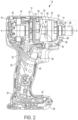
FIG. 2 is a side view of the impact tool ofFIG. 1 with a portion of the housing removed. -
FIG. 3 is an exploded view of the motor, transmission, and impact mechanism of the impact tool ofFIG. 1 . -
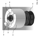
FIG. 4 is a perspective view of an embodiment of an impact mechanism. -
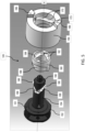
FIG. 5 is an exploded view of the impact mechanism ofFIG. 4 -
FIG. 6 is a partially exploded view of the impact mechanism ofFIG. 4 -
FIG. 7 is a perspective view of a carrier, a cam shaft and cam ring of the impact mechanism ofFIG. 4 . -
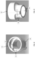
FIGS. 8 and 9 are perspective views of a cam ring of the impact mechanism ofFIG. 4 . -
FIG. 10 is a perspective view, partially in section of a cam ring of the impact mechanism ofFIG. 4 . -
FIGS. 11 and 12 are cross-sectional views of the impact mechanism ofFIG. 4 . -
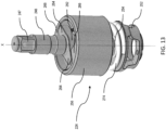
FIG. 13 is a perspective view of another embodiment of an impact mechanism. -
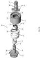
FIG. 14 is an exploded view of the impact mechanism ofFIG. 13 . -
FIG. 15 is a cross-sectional view of the impact mechanism ofFIG. 13 showing the hammer in a forward position. -
FIG. 16 is a cross-sectional view of the impact mechanism ofFIG. 13 showing the hammer in a rearward position. - Referring to
FIGS. 1 and2 , in an embodiment, animpact tool 10 has ahousing 12 having afront end portion 14 and arear end portion 16. Thehousing 12 includes amotor housing portion 18 that contains arotary motor 20 and atransmission housing portion 22 that contains atransmission 23 and animpact mechanism 24. Thetransmission 23 andimpact mechanism 24 transmit rotary motion from themotor 20 to anoutput spindle 26, as described in greater detail below. Coupled to theoutput spindle 26 is atool holder 29 for retaining a tool (e.g., a drill bit, screw driving bit, a socket, etc., not shown). Theoutput spindle 26 and thetool holder 29 together define and extend along a tool axis X. As shown, thetool holder 29 quick release hex bit retention mechanism. In other embodiments, the tool holder may be a non-quick release hex bit retention mechanism, a keyed or keyless chuck, or a square socket. Further details regarding exemplary tool holders are set forth in commonly-ownedU.S. Patent Application No. 12/394,426 . - Extending downward and slightly rearward of the
housing 12 is ahandle 30 in a pistol grip formation. Thehandle 30 has aproximal portion 32 coupled to thehousing 12 and adistal portion 34 coupled to abattery receptacle 28. Themotor 20 may be powered by an electrical power source, such as a DC power source or battery (not shown), that is coupled to thebattery receptacle 28, or by an AC power source. Atrigger 36 is coupled to thehandle 30 adjacent thehousing 12. Thetrigger 36 connects the electrical power source to themotor 20 via acontroller 40 and may control an amount of power delivery to themotor 20, as described in greater detail below. A light unit (e.g., an LED) 38 may be disposed on thefront end portion 14 of thehousing 12, just below thetool holder 29 to illuminate an area in front of thetool holder 29.
Alternatively, the light unit may be disposed on a front end portion of thebattery receptacle 28 Power delivery to thelight unit 38 may be controlled by thetrigger 36 and thecontroller 40, or by a separate switch on the tool. - Referring also to
FIG. 3 , in an embodiment, thetransmission 23 may be a planetary transmission that includes a pinion or sun gear 44 that is coupled to anoutput shaft 46 of themotor 20 and that extends along the axis X. One or more planet gears 48 surround and have teeth that mesh with the teeth on the sun gear 44. Anouter ring gear 50 is rotationally fixed to thehousing 12 and centered on the axis X with its internal teeth meshing with the teeth on the planet gears 48. The planet gears 48 are pivotally coupled to aplanet carrier 52. When themotor 20 is energized, it causes themotor output shaft 46 and the sun gear 44 to rotate about the axis X. Rotation of the sun gear 44 causes the planet gears 48 to orbit the sun gear 44 about the axis X, which in turn causes theplanet carrier 52 to rotate about the axis X at a reduced speed relative to the rotational speed of themotor output shaft 46. In the illustrated embodiment, only a single planetary stage is shown. It should be understood that the transmission may include multiple planetary stages that may provide for multiple speed reductions, and that each stage can be selectively actuated to provide for multiple different output speeds of the planet carrier. Further, the transmission may include a different type of gear system such as a parallel axis transmission, a spur gear transmission, or a right angle transmission. - In an embodiment, the
impact mechanism 24 may include acam shaft 54 extending along the tool axis X and fixedly coupled to theplanet carrier 52 so that they rotate together. Received over thecam shaft 54 is acylindrical hammer 56 that is configured to move rotationally and axially relative to thecam shaft 54. Thecam shaft 54 also has afront end 58 of smaller diameter that is rotatably received in anaxial opening 60 in theoutput spindle 26. Fixedly coupled to a rear end of theoutput spindle 26 is ananvil 62 having tworadial projections 64. Thehammer 56 has twohammer projections 66 on its front end that lie in the same rotational plane as theradial projections 64 of theanvil 62 so that eachhammer projection 66 may engage acorresponding anvil projection 64 in a rotating direction. In other embodiments, the hammer and/or the anvil may have different numbers of projections. - Formed on an outer wall of the
cam shaft 54 is a pair of angled or curved (e.g., rear-facing V-shaped, U-shaped, or parabolic)cam grooves 68 with their open ends facing toward therear end portion 16 of thehousing 12. A corresponding pair of angled or curved (e.g., forward-facing V-shaped, U-shaped, or parabolic) cam grooves (not shown) is formed on an interior wall of thehammer 56 with their open ends facing toward thefront end portion 14 of thehousing 12. One ormore balls 72 are received in and ride along each of thecam grooves 68 on the cam shaft and the cam grooves on the hammer to couple thehammer 56 to thecam shaft 54. Acompression spring 74 is received in a cylindrical recess in thehammer 56 and abuts a forward face of theplanet carrier 52. Thespring 74 biases thehammer 56 toward theanvil 62 so that thehammer projections 66 engage thecorresponding anvil projections 64. - At low torque levels, the
impact mechanism 24 transmits torque to theoutput spindle 26 in a rotary mode. In the rotary mode, thecompression spring 74 maintains thehammer 56 in its most forward position so that thehammer projections 66 engage theanvil projections 64. This causes thecam shaft 54, thehammer 56, theanvil 62 and the output spindle to rotate together as a unit about the tool axis X-X so that theoutput spindle 26 has substantially the same rotational speed as thecam shaft 54. - As the torque increases to exceed a torque transition threshold (also known as a trip torque), the
impact mechanism 24 transmits torque to theoutput spindle 26 in an impact mode. In the impact mode, thehammer 56 moves axially rearwardly against the force of thespring 74. This decouples thehammer projections 66 from theanvil projections 64 so that the anvil is decoupled from thecam shaft 54. Meanwhile, thecam shaft 54 continues to be driven by themotor 20 andtransmission 23. As this occurs, thehammer 56 moves axially rearwardly relative to theanvil 62 by the movement of theballs 72 rearwardly in the first angled or curved (e.g., V-shaped, U-shaped, parabolic)cam grooves 68. When the spring force and the torque of the motor overcomes the inertia of the hammer, thespring 74 drives thehammer 56 axially forward such that thehammer projections 66 rotationally strike theanvil projections 64, imparting a rotational impact to theoutput spindle 26. This impacting operation repeats as long as the torque on theoutput spindle 26 continues to exceed the torque transition threshold. This application refers to this operation as impact operation. - The transition torque threshold for when the
impact mechanism 24 transitions from the rotary operation to impact operation is a function of various factors, including the mechanical characteristics of the components of theimpact mechanism 24, such as the inertia of thehammer 56 and the force and rate of thespring 74, motor performance characteristics, such as motor speed or acceleration, and external characteristics, such as the tightness of the joint at the workpiece, the fastener, and/or loading of the output spindle. Thus, under different conditions of operation, the transition torque threshold may vary. - Referring to
FIGS. 4-12 , in another example, animpact mechanism 124 includes aplanet carrier 152, which carries the planet gears of the transmission and acam shaft 154 extending along the tool axis X-X and fixedly coupled to theplanet carrier 152 so that they rotate together. Received over thecam shaft 154 is acylindrical cam ring 180 and received over thecam ring 180 is a generallycylindrical hammer 156, each of which are configured to move rotationally and axially relative to thecam shaft 154. Thecam shaft 154 also has afront end 158 of smaller diameter that is rotatably received in an axial opening in an anvil (not shown), which has a similar configuration as theanvil 62 described above and theanvil 262 described below. Thehammer 156 has twohammer projections 166 on its front end that may engage two corresponding anvil projections on the anvil in a rotating direction. In other embodiments, the hammer and/or the anvil may have different numbers of projections. - Formed on an outer wall of the
cam shaft 154 is a first pair of rearward-facing angled or curved (e.g., V-shaped, U-shaped, parabolic)cam grooves 168 with their open ends facing toward theplanet carrier 152 of thecam shaft 154. A corresponding first pair of forward-facing angled or curved (e.g., V-shaped, U-shaped, parabolic)cam grooves 182 is formed on aninterior wall 184 of thecam ring 180 with their open ends facing toward thefront end portion 158 of thecam shaft 154. One or morefirst balls 188 are received in and ride along the first pair of rearward-facingcam grooves 168 and the first pair of forward-facingcam grooves 182 to couple thecam ring 180 to thecam shaft 154. - Formed on an outer wall of the
cam ring 180 is a second pair of rearward-facing angled or curved (e.g., V-shaped, U-shaped, parabolic)cam grooves 186 with their open ends facing toward theplanet carrier 152 of thecam shaft 154. A corresponding second pair of forward-facing angled or curved (e.g., V-shaped, U-shaped, parabolic)cam grooves 170 is formed on aninterior wall 173 of thehammer 156 with their open ends facing toward thefront end portion 158 of thecam shaft 154. One or moresecond balls 172 are received in and ride along each of the second pair of rearward-facingcam grooves 186 and the second pair of forward-facingcam grooves 170 to couple thehammer 156 to thecam ring 180. Optionally, the second pair of rearward-facingcam grooves 186 on thecam ring 180 may be angularly offset from the first pair of rearward-facingcam grooves 168 on the cam shaft 154 (e.g., by 90 degrees) and the second pair of forward-facingcam grooves 170 on thehammer 156 may be angularly offset from the first pair of forward-facingcam grooves 182 on thecam ring 180. - A compression spring (not shown), similar to
spring 74 described above, abuts aforward face 151 of theplanet carrier 152 and aninterior shoulder 171 inside thehammer 156 to bias thehammer 156 away from theplanet carrier 152 and toward the anvil. At low torque levels, the compression spring maintains thecam ring 180 in its forwardmost position relative to thecam shaft 154 and thehammer 156 in its forwardmost position relative to thecam ring 180 so that thehammer projections 166 engage the anvil projections. This causes theimpact mechanism 124 to operate in a rotary mode, where thecam shaft 154, thecam ring 180, thehammer 156, and the anvil rotate together as a unit about the axis X-X at substantially the same rotational speed. - As the torque increases to exceed a torque transition threshold, the
impact mechanism 124 transmits torque to the anvil in an impact mode. In the impact mode, as the torque increases, thefirst balls 188 move along the first pair of rearward-facingcam grooves 168 and the first set of forward-facingcam grooves 182, so that thecam ring 180 moves rotatably and axially rearward relative to thecam shaft 154. At the same time, thesecond balls 172 move along the second pair of rearward-facingcam grooves 186 and the second set of forward-facingcam grooves 170, so that thehammer 156 moves rotatably and axially rearward relative to thecam ring 180 against the force of the spring. This decouples thehammer projections 166 from the anvil projections so that the anvil is decoupled from the cam shaft. Meanwhile, thecamshaft 154, thecam ring 180, and thehammer 156 continue to be driven. As this occurs, thecam ring 180 and thehammer 156 move axially rearwardly relative to the anvil by the movement of the balls rearwardly in the cam grooves. When the spring force and the torque of the motor overcomes the inertia of the hammer, the spring drives thecam ring 180 rotationally and axially forward relative to thecam shaft 154 and thehammer 156 rotationally and axially forward relative to thecam ring 180, such that the rotational speed of thehammer 156 exceeds the rotational speed of thecam shaft 154. This causes thehammer projections 166 to rotationally strike the anvil projections, imparting a rotational impact to the anvil. This impacting operation repeats as long as the torque on the output spindle continues to exceed a torque threshold. - The
impact mechanism 124 provides at least the following potential advantages as compared to the existing impact mechanism shown 24 inFig. 1 . For example, the addition of a cam ring that is nested between the cam shaft and the hammer allows the first rearward-facing and forward-facingcam grooves cam grooves cam grooves 68 in theimpact mechanism 24 ofFig. 2 . This enables a stiffer spring to be used while achieving the same or greater torque output with less axial travel of the hammer. In addition, the cam ring that is nested between the cam shaft and the hammer enables greater rotational travel of the hammer relative to the cam shaft in the same or smaller axial distance of travel, which may enable greater torque output. - Referring to
FIGS. 13-16 , in another example, animpact mechanism 224 for an impact wrench includes aplanet carrier 252, which carries the planet gears of the transmission and acam shaft 254 extending along the tool axis X-X and fixedly coupled to theplanet carrier 252 so that they rotate together. Received over thecam shaft 254 is acylindrical cam ring 280 and received over thecam ring 280 is a generallycylindrical hammer 256, each of which are configured to move rotationally and axially relative to thecam shaft 254. Thecam shaft 254 also has afront end 258 of smaller diameter that is rotatably received in an axial opening in ananvil 262. Theanvil 262 has twoanvil projections 264 and is coupled to anoutput shaft 246 with a squaredrive tool holder 247 for retaining a socket tool on the output shaft. Thehammer 256 has twohammer projections 266 on its front end that may engage the twocorresponding anvil projections 264 on the anvil in a rotating direction. In other embodiments, the hammer and/or the anvil may have different numbers of projections. - Formed on an outer wall of the
cam shaft 254 is a first pair of rearward-facing angled or curved (e.g., V-shaped, U-shaped, parabolic)cam grooves 268 with their open ends facing toward theplanet carrier 252 of thecam shaft 254. A corresponding first pair of forward-facing angled or curved (e.g., V-shaped, U-shaped, parabolic)cam grooves 282 is formed on an interior wall of thecam ring 280 with their open ends facing toward thefront end portion 258 of thecam shaft 254. One or morefirst balls 288 are received in and ride along the first pair of rearward-facingcam grooves 268 and the first pair of forward-facingcam grooves 282 to couple thecam ring 280 to thecam shaft 254. - Formed on an outer wall of the
cam ring 280 is a second pair of rearward-facing angled or curved (e.g., V-shaped, U-shaped, parabolic)cam grooves 286 with their open ends facing toward theplanet carrier 252 of thecam shaft 254. A corresponding second pair of forward-facing angled or curved (e.g., V-shaped, U-shaped, parabolic)cam grooves 270 is formed on an interior wall of thehammer 256 with their open ends facing toward thefront end portion 258 of thecam shaft 254. One or moresecond balls 272 are received in and ride along each of the second pair of rearward-facingcam grooves 286 and the second pair of forward-facingcam grooves 270 to couple thehammer 256 to thecam ring 280. Optionally, the second pair of rearward-facingcam grooves 286 on thecam ring 280 may be angularly offset from the first pair of rearward-facingcam grooves 268 on the cam shaft 254 (e.g., by 90 degrees) and the second pair of forward-facingcam grooves 270 on thehammer 256 may be angularly offset from the first pair of forward-facingcam grooves 282 on thecam ring 280. - A
first compression spring 274 abuts aforward face 251 of theplanet carrier 252 and an interior shoulder inside thehammer 256 to bias thehammer 256 away from theplanet carrier 252 and toward theanvil 262. Optionally, asecond compression spring 275 abuts theforward face 251 of theplanet carrier 252 and a rear end portion of thecam ring 280 to bias thecam ring 280 away from theplanet carrier 252 and toward the anvil. Thesecond spring 275 may provide a force to supplement the force of the first spring. The first and second springs may have the same or different spring constants, lengths, wire diameters, and force profiles. - As shown in
Fig. 15 , at low torque levels, thesprings cam ring 280 and thehammer 256 in their forwardmost position relative to thecam shaft 254 so that thehammer projections 266 engage theanvil projections 264. This causes theimpact mechanism 224 to operate in a rotary mode, where thecam shaft 254, thecam ring 280, thehammer 256, and the anvil rotate together as a unit about the axis X-X at substantially the same rotational speed. - As shown in
Fig. 16 , when the torque increases to exceed a torque transition threshold, theimpact mechanism 224 transmits torque to the anvil in an impact mode. In the impact mode, as the torque increases, thefirst balls 288 move along the first pair of rearward-facingcam grooves 268 and the first set of forward-facingcam grooves 282, so that thecam ring 280 moves rotatably and axially rearward relative to thecam shaft 254. At the same time, thesecond balls 272 move along the second pair of rearward-facingcam grooves 286 and the second set of forward-facingcam grooves 270, so that thehammer 256 moves rotatably and axially rearward relative to thecam ring 280 against the force of the springs. This decouples thehammer projections 266 from the anvil projections so that the anvil is decoupled from the cam shaft. Meanwhile, thecamshaft 254, thecam ring 280, and thehammer 256 continue to be driven. As this occurs, thecam ring 280 and thehammer 256 move axially rearwardly relative to the anvil by the movement of the balls rearwardly in the cam grooves. When the spring force and the torque of the motor overcomes the inertia of the hammer, the spring drives thecam ring 280 rotationally and axially forward relative to thecam shaft 254 and thehammer 256 rotationally and axially forward relative to thecam ring 280, such that the rotational speed of thehammer 256 exceeds the rotational speed of thecam shaft 254. This causes thehammer projections 266 to rotationally strike theanvil projections 264, imparting a rotational impact to the anvil. This impacting operation repeats as long as the torque on the output spindle continues to exceed a torque threshold. - In alternative designs, the impact mechanism may have multiple first springs that bias the hammer axially forward and/or multiple second springs between the planet carrier and the cam ring that bias the cam ring axially forward. The second spring may be nested inside the first spring or vice versa. The springs may have similar or different spring constants, wire diameters, and/or lengths. In each of these designs, the spring(s) cause the hammer and/or the cam ring to be biased axially forward away from the transmission and toward the anvil.
Claims (12)
- A powered rotary impact tool comprising:a housing;a motor disposed in the housing;an output shaft;a transmission configured to be driven by the motor; andan impact mechanism configured to be driven by the transmission and to transmit torque from the transmission to the output tool holder, the impact mechanism includinga cam shaft extending along an axis and configured to be rotatably driven by an output member of the transmission, the cam shaft defining a first cam groove on an outer surface of the cam shaft;a cam ring received over the cam shaft and defining a second cam groove on an inner surface of the cam ring and a third cam groove on an outer surface of the cam ring;a hammer received over the cam ring and defining a fourth cam groove on an inner surface of the hammer and including a hammer projection on a front portion of the hammer;an anvil coupled to the output shaft for rotation with the output shaft, the anvil having an anvil projection configured to be selectively engaged by the hammer projection;a first spring configured to bias the hammer toward the anvil;a first ball received in the first cam groove and the second cam groove and configured to couple the cam ring to the cam shaft for rotational and axial movement relative to the cam shaft; anda second ball received in the third cam groove and the fourth cam groove and configured to couple the hammer to the cam ring for rotational and axial movement relative to the cam ring,wherein when torque on the output shaft is less than or equal to a threshold amount, the first spring maintains the hammer in its forwardmost position relative to the cam shaft so that the hammer projection engages the anvil projection, and the cam shaft, the cam ring, the hammer, and the anvil rotate together as a unit about the axis, andwherein when torque on the output shaft increases to exceeds the threshold amount, the first ball moves along the first and second cam grooves so that the cam ring moves rotatably and axially rearward relative to the cam shaft, and the second ball moves along the third and fourth cam grooves, so that the hammer moves rotatably and axially rearward relative to the cam ring, which decouples the hammer projection from the anvil projection, and, when the first spring force and the torque of the motor overcomes the inertia of the hammer, the first spring drives the cam ring rotationally and axially forward relative to the cam shaft and the hammer rotationally and axially forward relative to the cam ring, such that the hammer projection rotationally strikes the anvil projection to impart a rotational impact to the anvil.
- The rotary impact tool of claim 1, wherein the third cam groove and the fourth cam groove are angled or curved.
- A powered rotary impact tool comprising:a cam shaft extending along an axis and configured to be rotatably driven upon actuation of the power tool, the cam shaft defining a first cam groove on an outer surface of the cam shaft;a cam ring received over the cam shaft and defining a second cam groove on an inner surface of the cam ring and a third cam groove on an outer surface of the cam ring;a hammer received over the cam ring and defining a fourth cam groove on an inner surface of the hammer and including a hammer projection on a front portion of the hammer;an anvil including an output shaft and an anvil projection configured to be selectively engaged by the hammer projection;a first spring configured to bias the hammer toward the anvil;a first ball received in the first cam groove and the second cam groove and configured to couple the cam ring to the cam shaft for rotational and axial movement relative to the cam shaft; anda second ball received in the third cam groove and the fourth cam groove and configured to couple the hammer to the cam ring for rotational and axial movement relative to the cam ring,wherein when torque on the output shaft is less than or equal to a threshold amount, the first spring maintains the hammer in its forwardmost position relative to the cam shaft so that the hammer projection engages the anvil projection, and the cam shaft, the cam ring, the hammer, and the anvil rotate together as a unit about the axis, andwherein when torque on the output shaft increases to exceed the threshold amount, the first ball moves along the first and second cam grooves so that the cam ring moves rotatably and axially rearward relative to the cam shaft, and the second ball moves along the third and fourth cam grooves, so that the hammer moves rotatably and axially rearward relative to the cam ring, which decouples the hammer projection from the anvil projection, and, when the first spring force and the torque of the motor overcomes the inertia of the hammer, the first spring drives the cam ring rotationally and axially forward relative to the cam shaft and the hammer rotationally and axially forward relative to the cam ring, such that the hammer projection rotationally strikes the anvil projection to impart a rotational impact to the anvil.
- The rotary impact tool of any of claims 1 to 3, wherein the first cam groove and the second cam groove are angled or curved.
- The rotary impact tool of any of the previous claims, wherein the first cam groove is V-shaped with an open end of the first cam groove facing rearward away from the anvil.
- The rotary impact tool of any of the previous claims , wherein the second cam groove is V-shaped with an open end of the second cam groove facing forward toward the anvil.
- The rotary impact tool of any of the previous claims, wherein the third cam groove is V-shaped with an open end of the first cam groove facing rearward away from the anvil.
- The rotary impact tool of any of the previous claims , wherein the fourth cam groove is V-shaped with an open end of the second cam groove facing forward toward the anvil.
- The rotary impact tool of any of the previous claims, wherein the third cam groove is angularly offset from the first cam groove and the fourth cam groove is angularly offset from the second cam groove.
- The rotary impact tool of any of the previous claims, wherein the first spring is disposed between the transmission and the hammer.
- The rotary impact tool of any of the previous claims , further comprising a second spring disposed between the transmission and the cam ring.
- A powered rotary impact tool comprising:a housing;a motor disposed in the housing;an output shaft;a tool holder coupled to the output shaft for rotation with the output shaft;a transmission configured to be driven by the motor; andan impact mechanism configured to be driven by the transmission and to transmit torque from the transmission to the output tool holder, the impact mechanism includinga cam shaft extending along an axis and configured to be rotatably driven by an output member of the transmission, the cam shaft defining a first V-shaped cam groove on an outer surface of the cam shaft;a cam ring received over the cam shaft and defining a second V-shaped cam groove on an inner surface of the cam ring facing an opposite direction from the first V-shaped cam groove, and a third V-shaped cam groove on an outer surface of the cam ring offset angularly from the first V-shaped cam groove;a hammer received over the cam ring and defining a fourth V-shaped cam groove on an inner surface of the hammer facing an opposite direction from the third V-shaped cam groove and offset angularly from the second V-shaped cam groove, the hammer including a hammer projection on a front portion of the hammer;an anvil coupled to the output shaft for rotation with the output shaft, the anvil having an anvil projection configured to be selectively engaged by the hammer projection;a spring between the transmission and the hammer to bias the hammer toward the anvil;a first ball received in the first cam groove and the second cam groove and configured to couple the cam ring to the cam shaft for rotational and axial movement relative to the cam shaft; anda second ball received in the third cam groove and the fourth cam groove and configured to couple the hammer to the cam ring for rotational and axial movement relative to the cam ring,wherein when torque on the output shaft is less than or equal to a threshold amount, the spring maintains the hammer in its forwardmost position relative to the cam shaft so that the hammer projection engages the anvil projection, and the cam shaft, the cam ring, the hammer, and the anvil rotate together as a unit about the axis, andwherein when torque on the output shaft increases to exceed the threshold amount, the first ball moves along the first and second cam grooves so that the cam ring moves rotatably and axially rearward relative to the cam shaft, and the second ball moves along the third and fourth cam grooves, so that the hammer moves rotatably and axially rearward relative to the cam ring, which decouples the hammer projection from the anvil projection, and, when the spring force and the torque of the motor overcomes the inertia of the hammer, the spring drives the cam ring rotationally and axially forward relative to the cam shaft and the hammer rotationally and axially forward relative to the cam ring, such that the hammer projection rotationally strikes the anvil projection to impart a rotational impact to the anvil.
Applications Claiming Priority (1)
| Application Number | Priority Date | Filing Date | Title |
|---|---|---|---|
| US202363517277P | 2023-08-02 | 2023-08-02 |
Publications (1)
| Publication Number | Publication Date |
|---|---|
| EP4509266A1 true EP4509266A1 (en) | 2025-02-19 |
Family
ID=92108448
Family Applications (1)
| Application Number | Title | Priority Date | Filing Date |
|---|---|---|---|
| EP24191590.9A Pending EP4509266A1 (en) | 2023-08-02 | 2024-07-29 | Impact power tool and impact mechanism |
Country Status (2)
| Country | Link |
|---|---|
| US (2) | US12415259B2 (en) |
| EP (1) | EP4509266A1 (en) |
Families Citing this family (2)
| Publication number | Priority date | Publication date | Assignee | Title |
|---|---|---|---|---|
| US12415259B2 (en) * | 2023-08-02 | 2025-09-16 | Black & Decker Inc. | Impact power tool and impact mechanism |
| JP2025063454A (en) * | 2023-10-04 | 2025-04-16 | 株式会社マキタ | Impact Tools |
Citations (3)
| Publication number | Priority date | Publication date | Assignee | Title |
|---|---|---|---|---|
| EP0839612A1 (en) * | 1996-10-31 | 1998-05-06 | Snap-On Tools Corporation | Reversible high impact mechanism |
| US20190344411A1 (en) | 2015-02-27 | 2019-11-14 | Black & Decker Inc. | Impact tool with control mode |
| EP4163058A1 (en) * | 2021-07-16 | 2023-04-12 | Black & Decker Inc. | Impact power tool |
Family Cites Families (49)
| Publication number | Priority date | Publication date | Assignee | Title |
|---|---|---|---|---|
| US2263709A (en) | 1939-12-11 | 1941-11-25 | Cleveland Pneumatic Tool Co | Clutch device |
| US2561913A (en) | 1945-09-29 | 1951-07-24 | Adiel Y Dodge | Overload release coupling |
| US2523584A (en) | 1949-05-18 | 1950-09-26 | Raymond J Miller | Tap chuck with overload coupling |
| US2745528A (en) * | 1953-01-05 | 1956-05-15 | Chicago Pneumatic Tool Co | Reversible impact wrench |
| GB852752A (en) | 1957-01-08 | 1960-11-02 | Bosch Gmbh Robert | Improvements in motor driven rotary percussion apparatus |
| US3001429A (en) * | 1959-04-16 | 1961-09-26 | Master Power Corp | Rotary impact wrench |
| US3001428A (en) * | 1960-02-23 | 1961-09-26 | Master Power Corp | Rotary impact wrench |
| US3106274A (en) | 1960-09-13 | 1963-10-08 | Albertson & Co Inc | Rotary impact mechanism |
| US3053360A (en) | 1960-12-30 | 1962-09-11 | Albertson & Co Inc | Rotary impact wrench mechanism |
| GB1266345A (en) | 1968-04-17 | 1972-03-08 | ||
| US4249617A (en) | 1979-10-22 | 1981-02-10 | Cox James D Jr | Portable one-hand operated rotary torque producing tool |
| DE3821594A1 (en) | 1988-06-27 | 1989-12-28 | Hilti Ag | MOTORIZED HAND TOOL |
| DE4328599C2 (en) | 1992-08-25 | 1998-01-29 | Makita Corp | Rotary striking tool |
| US5346023A (en) | 1993-02-11 | 1994-09-13 | Hitachi Koki Company Limited | Slipping torque changing apparatus for impact tool |
| US5409324A (en) | 1993-06-25 | 1995-04-25 | North Houston Machine, Inc. | High strength, quick connect/disconnect coupling |
| US5588772A (en) | 1993-06-25 | 1996-12-31 | North Houston Machine, Inc. | High strength, quick connect/disconnect coupling |
| US5588496A (en) | 1994-07-14 | 1996-12-31 | Milwaukee Electric Tool Corporation | Slip clutch arrangement for power tool |
| US6733414B2 (en) * | 2001-01-12 | 2004-05-11 | Milwaukee Electric Tool Corporation | Gear assembly for a power tool |
| GB0213289D0 (en) | 2002-06-11 | 2002-07-24 | Black & Decker Inc | Rotary hammer |
| DE102006000252A1 (en) * | 2006-05-30 | 2007-12-06 | Hilti Ag | Hand tool with slip clutch |
| JP5136787B2 (en) | 2008-08-29 | 2013-02-06 | 日立工機株式会社 | Rotating hammer tool |
| TWM367039U (en) * | 2009-06-17 | 2009-10-21 | Top Gearbox Industry Co Ltd | Output style-switching device |
| US8925646B2 (en) | 2011-02-23 | 2015-01-06 | Ingersoll-Rand Company | Right angle impact tool |
| US9592600B2 (en) * | 2011-02-23 | 2017-03-14 | Ingersoll-Rand Company | Angle impact tools |
| DE102011089910A1 (en) * | 2011-12-27 | 2013-06-27 | Robert Bosch Gmbh | Hand tool device |
| DE102011089913A1 (en) | 2011-12-27 | 2013-06-27 | Robert Bosch Gmbh | Hand tool device |
| JP2013144341A (en) | 2012-01-16 | 2013-07-25 | Makita Corp | Reciprocating tool |
| DE102012209446A1 (en) * | 2012-06-05 | 2013-12-05 | Robert Bosch Gmbh | Hand machine tool device |
| DE102012210298A1 (en) | 2012-06-19 | 2013-12-19 | Zf Friedrichshafen Ag | Connecting device for two shafts with a stop damper |
| US9022888B2 (en) | 2013-03-12 | 2015-05-05 | Ingersoll-Rand Company | Angle impact tool |
| DE102013212753A1 (en) * | 2013-06-28 | 2014-12-31 | Robert Bosch Gmbh | Percussion device |
| JP2015009310A (en) | 2013-06-28 | 2015-01-19 | 日立工機株式会社 | Impact tool |
| EP3251803B1 (en) | 2015-01-30 | 2022-10-26 | Koki Holdings Co., Ltd. | Work machine |
| DE102015204807A1 (en) * | 2015-03-17 | 2016-09-22 | Robert Bosch Gmbh | Hand tool and mechanical percussion |
| JP6607502B2 (en) | 2016-08-31 | 2019-11-20 | パナソニックIpマネジメント株式会社 | Impact rotary tool |
| JP6719084B2 (en) | 2016-09-27 | 2020-07-08 | パナソニックIpマネジメント株式会社 | Rotary impact tool |
| JP6832509B2 (en) | 2017-03-27 | 2021-02-24 | パナソニックIpマネジメント株式会社 | Rotary striking tool |
| DE102018207628A1 (en) | 2018-05-16 | 2019-11-21 | Zf Friedrichshafen Ag | Positive locking element for non-rotatable connection of rotatable transmission components |
| CN110653744A (en) * | 2018-06-29 | 2020-01-07 | 创科(澳门离岸商业服务)有限公司 | Anvils for power tools and power tools |
| EP3898101A4 (en) | 2018-12-21 | 2022-11-30 | Milwaukee Electric Tool Corporation | HIGH TORQUE IMPACT TOOL |
| US11351663B2 (en) * | 2019-12-24 | 2022-06-07 | Ingersoll-Rand Industrial U.S., Inc. | Latching hammer impact wrench |
| US11872680B2 (en) * | 2021-07-16 | 2024-01-16 | Black & Decker Inc. | Impact power tool |
| JP7762058B2 (en) * | 2021-12-17 | 2025-10-29 | 株式会社マキタ | Impact tools |
| JP7727520B2 (en) * | 2021-12-17 | 2025-08-21 | 株式会社マキタ | Impact tools |
| JP7783781B2 (en) * | 2022-05-16 | 2025-12-10 | 株式会社マキタ | Impact tools |
| US12138753B2 (en) * | 2022-06-13 | 2024-11-12 | Makita Corporation | Impact tool |
| US20240058927A1 (en) * | 2022-08-22 | 2024-02-22 | Makita Corporation | Impact tool |
| US20240326203A1 (en) * | 2023-03-28 | 2024-10-03 | Snap-On Incorporated | Impact wrench |
| US12415259B2 (en) * | 2023-08-02 | 2025-09-16 | Black & Decker Inc. | Impact power tool and impact mechanism |
-
2024
- 2024-07-24 US US18/782,918 patent/US12415259B2/en active Active
- 2024-07-29 EP EP24191590.9A patent/EP4509266A1/en active Pending
-
2025
- 2025-08-22 US US19/307,550 patent/US20250375862A1/en active Pending
Patent Citations (3)
| Publication number | Priority date | Publication date | Assignee | Title |
|---|---|---|---|---|
| EP0839612A1 (en) * | 1996-10-31 | 1998-05-06 | Snap-On Tools Corporation | Reversible high impact mechanism |
| US20190344411A1 (en) | 2015-02-27 | 2019-11-14 | Black & Decker Inc. | Impact tool with control mode |
| EP4163058A1 (en) * | 2021-07-16 | 2023-04-12 | Black & Decker Inc. | Impact power tool |
Also Published As
| Publication number | Publication date |
|---|---|
| US12415259B2 (en) | 2025-09-16 |
| US20250375862A1 (en) | 2025-12-11 |
| US20250042008A1 (en) | 2025-02-06 |
Similar Documents
| Publication | Publication Date | Title |
|---|---|---|
| US12415259B2 (en) | Impact power tool and impact mechanism | |
| US12576501B2 (en) | Impact power tool | |
| US12304035B2 (en) | Power tool | |
| EP2246156B1 (en) | Power tool impact mechanism | |
| US7806198B2 (en) | Hybrid impact tool | |
| US9016395B2 (en) | Impact tool | |
| CN110153958B (en) | Hand-held tool | |
| US11318596B2 (en) | Power tool having hammer mechanism | |
| US9415498B2 (en) | Hammer mechanism | |
| CN1745973A (en) | Hand tools with impact drive and reduction mechanism | |
| WO2011103320A2 (en) | Impact device | |
| US11872680B2 (en) | Impact power tool | |
| EP1120199A2 (en) | Hydraulic impulse rotary tool | |
| WO2020162268A1 (en) | Screw fastening tool | |
| JP4291179B2 (en) | Impact driver | |
| EP4163058B1 (en) | Impact power tool | |
| EP3812097B1 (en) | Rotary hammer | |
| JP6004294B2 (en) | Impact rotary tool | |
| US9434059B2 (en) | Hammer mechanism | |
| WO2025049875A1 (en) | Power tool | |
| JP2004249418A (en) | Impact driver |
Legal Events
| Date | Code | Title | Description |
|---|---|---|---|
| PUAI | Public reference made under article 153(3) epc to a published international application that has entered the european phase |
Free format text: ORIGINAL CODE: 0009012 |
|
| STAA | Information on the status of an ep patent application or granted ep patent |
Free format text: STATUS: THE APPLICATION HAS BEEN PUBLISHED |
|
| AK | Designated contracting states |
Kind code of ref document: A1 Designated state(s): AL AT BE BG CH CY CZ DE DK EE ES FI FR GB GR HR HU IE IS IT LI LT LU LV MC ME MK MT NL NO PL PT RO RS SE SI SK SM TR |
|
| STAA | Information on the status of an ep patent application or granted ep patent |
Free format text: STATUS: REQUEST FOR EXAMINATION WAS MADE |
|
| 17P | Request for examination filed |
Effective date: 20250806 |