EP4507967B1 - Autonome uav-dienststation zur unterstützung von bvlos uavs und verfahren zu deren betrieb - Google Patents
Autonome uav-dienststation zur unterstützung von bvlos uavs und verfahren zu deren betrieb Download PDFInfo
- Publication number
- EP4507967B1 EP4507967B1 EP23754463.0A EP23754463A EP4507967B1 EP 4507967 B1 EP4507967 B1 EP 4507967B1 EP 23754463 A EP23754463 A EP 23754463A EP 4507967 B1 EP4507967 B1 EP 4507967B1
- Authority
- EP
- European Patent Office
- Prior art keywords
- storey
- uav
- autonomous
- battery
- module
- Prior art date
- Legal status (The legal status is an assumption and is not a legal conclusion. Google has not performed a legal analysis and makes no representation as to the accuracy of the status listed.)
- Active
Links
Images


Classifications
-
- B—PERFORMING OPERATIONS; TRANSPORTING
- B64—AIRCRAFT; AVIATION; COSMONAUTICS
- B64U—UNMANNED AERIAL VEHICLES [UAV]; EQUIPMENT THEREFOR
- B64U70/00—Launching, take-off or landing arrangements
- B64U70/90—Launching from or landing on platforms
- B64U70/97—Means for guiding the UAV to a specific location on the platform, e.g. platform structures preventing landing off-centre
-
- B—PERFORMING OPERATIONS; TRANSPORTING
- B64—AIRCRAFT; AVIATION; COSMONAUTICS
- B64U—UNMANNED AERIAL VEHICLES [UAV]; EQUIPMENT THEREFOR
- B64U50/00—Propulsion; Power supply
- B64U50/30—Supply or distribution of electrical power
- B64U50/39—Battery swapping
-
- B—PERFORMING OPERATIONS; TRANSPORTING
- B64—AIRCRAFT; AVIATION; COSMONAUTICS
- B64U—UNMANNED AERIAL VEHICLES [UAV]; EQUIPMENT THEREFOR
- B64U80/00—Transport or storage specially adapted for UAVs
- B64U80/20—Transport or storage specially adapted for UAVs with arrangements for servicing the UAV
-
- B—PERFORMING OPERATIONS; TRANSPORTING
- B64—AIRCRAFT; AVIATION; COSMONAUTICS
- B64U—UNMANNED AERIAL VEHICLES [UAV]; EQUIPMENT THEREFOR
- B64U80/00—Transport or storage specially adapted for UAVs
- B64U80/20—Transport or storage specially adapted for UAVs with arrangements for servicing the UAV
- B64U80/25—Transport or storage specially adapted for UAVs with arrangements for servicing the UAV for recharging batteries; for refuelling
-
- B—PERFORMING OPERATIONS; TRANSPORTING
- B64—AIRCRAFT; AVIATION; COSMONAUTICS
- B64U—UNMANNED AERIAL VEHICLES [UAV]; EQUIPMENT THEREFOR
- B64U80/00—Transport or storage specially adapted for UAVs
- B64U80/30—Transport or storage specially adapted for UAVs with arrangements for data transmission
Definitions
- the invention relates to construction of the autonomous UAV service station for support of BVLOS infrastructure of the autonomous flights, and to method of its operation.
- the invention falls into the field of aviation.
- UAVs unmanned aerial vehicles
- UAVs unmanned aerial vehicles
- Document US2021/0047055A1 describes the station that enables precision landing of UAV and that is arranged in such a way that it is capable to prevent the collision of the unmanned UAV with the station during landing.
- the described station includes the covering components to cover UAV when UAV is in interior space and landing area in the form of landing stand coupled to lift. At the moment UAV approaches the landing station, the covering portions are opened, and the lift coupled with the landing stand moves upwards. After UAV has landed safely on the landing stand, the lift will move downwards and at the same time the covering parts will close in order to cover UAV.
- document US2021/0047055A1 does not describe how to provide a more universal infrastructure to enable the use of UAVs for different types of tasks, by means of automation of payload exchange.
- the patent publication CN113276725B describes a power exchange station with battery replacement facility.
- the Korean patent KR101705838B1 discloses an automatic battery exchange system for drones.
- the US patent US10369975B2 discloses UAV base station.
- the patent publication TR2021021976A2 disclose an automatic battery change system for UAV and the Korean document KR102356575B1 describes a multi drone station.
- the present invention eliminates the above-mentioned problem related to UAV operation by providing the autonomous service station to support UAV charging and BVLOS (Beyond Visual Line of Sight) infrastructure of the autonomous flights and the method of its operation.
- BVLOS Beyond Visual Line of Sight
- An autonomous UAV service station is defined in claim 1.
- a method of operation of the autonomous UAV service station is defined in claim 4.
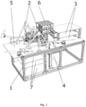
- the autonomous UAV service station has been designed to support BVLOS infrastructure of the autonomous flights, namely for support of UAV battery charging, and the method of its operation according to invention, which in its essence is formed by the components described below. It is multi-storey framed skeleton with full upper storey, on one side of which is placed the mechanical self-guided landing/take-off module "toboggan" with dimensions approximately 60x60x60cm, into which the autonomous UAV lands so that it is accurately guided to the module by means of this module and fits into a designated place at its bottom part.
- the self-guided landing/take-off module is preferably formed by two pyramids, each two edges of which are in contact with the respective arm of UAV when UAV is descending, thereby centres UAV in the x and y axis at the designated location by means of its own gravity.
- the multi-storey actuator horizontal extending/retracting module is located on the other side of the upper storey of the multi-storey framed skeleton.
- the framed skeleton preferably consists of coupled horizontal and vertical peripheral profiles with fastening points for variable fixing of the horizontal partitions.
- the framed skeleton preferably has solid bottom and/or rolling wheels, depending on the characteristics of the operational deployment of UAV, and the type of tasks to be performed with support of the autonomous service station.
- the autonomous service station In the case when the operational requirement for the autonomous service station is to replace only the battery on UAV, it is sufficient for the autonomous service station to have only a single-storey actuator horizontal extending/retracting module, according to an example not covered by the claims.
- the autonomous service station If the operational requirement for the autonomous service station is to replace the battery and another payload object such as the trolley, shipment, camera, etc. on UAV, it is sufficient for the autonomous service station to have the two-storey actuator horizontal extending/retracting module. Alternatively, if the operational requirement for the autonomous service station is to replace the battery and two other payload objects such as the trolley, shipment, camera, etc. on UAV, it is sufficient for the autonomous service station to have a three-storey actuator horizontal extending/retracting module.
- a vertical lift shaft is located between the mechanical self-guided landing/take-off module and the multi-storey actuator horizontal extending/retracting module, pointing below the upper storey of the multi-storey framed skeleton.
- the multi-storey lift is located in the vertical lift shaft. The travel rise of the multi-storey lift extends beyond the upper storey of the multi-storey framed skeleton.
- the control of the multi-storey lift up and down in the Z-axis is provided by step motor.
- the arrangement in which the multi-storey framed skeleton has open stowage boxes underneath the mechanical self-guided landing/take-off module for storing replaced parts for payload objects such as the trolley, shipment, camera, etc. is advantageous. It is also given the possibility, that the battery stowage boxes for battery storage would be connected to battery charger.
- the two-storey actuator horizontal stacking extending/retracting module is positioned below the upper storey of the multi-storey framed skeleton at the level of the multi-storey actuator horizontal stacking extending/retracting module.
- one actuator horizontal extending/retracting module is dedicated to battery replacement.
- the second actuator horizontal extending/retracting module is preferably intended to replace a functional component, e.g., the camera of UAV, or to connect another payload object of trolley, shipment.
- Beneath the upper storey of the multi-storey framed skeleton at the level of the multi-storey actuator horizontal extending/retracting module it is possible to advantageously place a power source such as the battery or electrical generator.
- the multi-storey lift In the autonomous UAV service station for support of BVLOS infrastructure of the autonomous flights, the multi-storey lift has empty storeys and, during operation, conveniently also has storeys with stored spare components such as the battery, trolley, shipment, and camera.
- the autonomous UAV service station for support of BVLOS infrastructure of autonomous flights is advantageously arranged as the swapping system to swap batteries in the drone and connect the battery connector by means of servo motor, while presenting the robotic system controlled remotely from the control station.
- the autonomous UAV service station for support of BVLOS infrastructure of the autonomous flights is extremely conveniently arranged as the swapping system for swapping payloads of various kinds (e.g., ortho camera, thermal camera, first aid package, autonomous vehicle) in the drone and possibly connecting their connector using the servo motor, which also represents the robotic system controlled remotely from the control station.
- various kinds e.g., ortho camera, thermal camera, first aid package, autonomous vehicle
- the autonomous UAV service station for support of BVLOS infrastructure of the autonomous flights preferably also has a communication unit and a battery charging block, where, after connecting the connector, the battery charging can be conveniently controlled from WAN via remote access, for example, by using the reading of the charging setup from a QR code on the battery set.
- the method of operating the autonomous UAV service station for support of BVLOS infrastructure of the autonomous flights is advantageously realized.
- the end members of the two-storey actuator horizontal stacking extending/retracting module are preferably used for moving the individual payloads and the battery from the individual lift storeys to the stowage boxes.
- one-storey actuator horizontal stacking extending/retracting module will be sufficient.
- the construction of the autonomous UAV service station for support of BVLOS infrastructure of the autonomous flights is described.
- the battery and payload exchange requirement is given for landing UAV.
- the basis of construction is the multi-storey framed skeleton 1 with full upper storey 5, on one side of which a mechanical self-guided landing/take-off module 2 "toboggan" with dimensions approximately 60x60x60cm is placed.
- the self-guided landing/take-off module 2 consists of two pyramids.
- the two-storey actuator horizontal extending/retracting module 3 is located on the other side of the upper storey 5 of the multi-storey framed skeleton 1.
- the framed skeleton 1 consists of coupled peripheral horizontal and vertical profiles with fastening points for variable attachment of the horizontal partitions. Framed skeleton 1 shall have the full bottom with possible mobile wheels.
- the vertical lift shaft 4 is provided between the mechanical self-guided landing/take-off module 2 and the two-storey actuator horizontal extending/retracting module 3, pointing below the upper storey 5 of the multi-storey framed skeleton 1.
- the multi-storey lift 6 with step motor is located. The stroke of the multi-storey lift 6 exceeds beyond the upper storey 5 of the multi-storey framed skeleton 1.
- the autonomous service station has only one-storey actuator horizontal extending/retracting module 3.
- the autonomous service station has a three-storey actuator horizontal extending/retracting module 3.
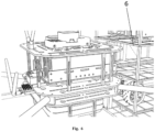
- the construction of the autonomous UAV service station is described for support of BVLOS infrastructure of the autonomous flights with extended functionality.
- the basis is the construction sufficiently described in the previous example.
- the functional extension is that the multi-storey framed skeleton 1 has open stowage boxes 7 located underneath the mechanical self-guided landing/take-off module 2 for storing replaced parts for payload objects such as the trolley, shipment, camera, etc.
- the stowage boxes 7 for storing the battery are connected to the battery charger.
- the two-storey actuator horizontal stacking extending/retracting module is located below the upper storey 5 of the multi-storey framed skeleton 1, at the level of the multi-storey actuator horizontal extending/retracting module 3, the two-storey actuator horizontal stacking extending/retracting module is located.
- the initial step is the landing of UAV on the mechanical self-guided landing/take-off module 2 between two-pyramid constructions, on the upper storey 5 of the multi- storey framed skeleton 1.
- the battery swapping system in UAV will be in operation, wherein the first actuator horizontal extending/retracting module is activated, and its gripping end member is extended to battery, grasps the battery, and in a reverse straight-line motion, ejects the battery from the UAV and stores it in the free upper storey of the lift 6.
- the storey of lift with the new charged battery will be raised to the level of the selected battery in UAV by stroke of lift 6.
- the first actuator horizontal extending/retracting module is activated, and its gripping end member is extended to battery, grasps the battery, and in a forward, straight-line motion, ejects the battery from UAV where it connects to the connector.
- the end member of the first actuator horizontal extending/retracting module is then returned to its initial position by backward straight-line motion.
- a swapping system will be in operation to exchange payload of various kinds e.g., ortho camera, thermal camera, first aid package, autonomous vehicle.
- a lift storey is lifted to the level of the payload area in UAV by horizontal displacement of lift 6, in which the payload of various kinds is stored e.g., ortho camera, thermal camera, first aid package, autonomous vehicle dedicated for attachment to UAV.
- the payload of various kinds e.g., ortho camera, thermal camera, first aid package, autonomous vehicle dedicated for attachment to UAV.
- the second actuator horizontal extending/retracting module 3 is activated, the gripping end member of which extends to payload, grasps the payload, and ejects the payload from UAV in a forward straight-line motion. Subsequently, the end member of the second actuator horizontal extending/retracting module is returned by backward straight-line motion to the initial position.
- Autonomous UAV service station for support of BVLOS infrastructure of the autonomous flights and the method of its operation according to invention is applicable in aviation.
Landscapes
- Engineering & Computer Science (AREA)
- Remote Sensing (AREA)
- Aviation & Aerospace Engineering (AREA)
- Transportation (AREA)
- Computer Networks & Wireless Communication (AREA)
- Chemical & Material Sciences (AREA)
- Combustion & Propulsion (AREA)
- Control Of Position, Course, Altitude, Or Attitude Of Moving Bodies (AREA)
- Arrangement Or Mounting Of Propulsion Units For Vehicles (AREA)
Claims (4)
- Eine autonome UAV-Service-Station zur Unterstützung der BVLOS-Infrastruktur (Flüge außerhalb der Sichtweite) für autonomes Fliegen, die Folgendes enthält:- ein mehrstöckiges Rahmenskelett (1);- ein mechanisches zielsuchendes Lande-/Aufstiegsmodul (2), das auf dem Obergeschoss (5) des mehrstöckigen Rahmenskeletts (1) platziert ist;
einen vertikalen Aufzugsschacht (4), platziert zwischen dem mechanischen zielsuchenden Lande-/Aufstiegsmodul (2) und dem horizontalen Aktuator-Auszieh-/Einschubmodul (3), das auf dem Obergeschoss (5) des mehrstöckigen Rahmenskeletts (1) platziert ist;- einen mehrstöckigen Aufzug (6), der im vertikalen Aufzugsschacht (4) platziert ist; wobei der Hub des mehrstöckigen Aufzugs (6) das Obergeschoss (5) des mehrstöckigen Rahmenskeletts (1) überragt; wobei das mehrstöckige Rahmenskelett (1) über offene Ablageboxen (7) verfügt, die unter dem mechanischen zielsuchsenden Lande-/Aufstiegsmodul (2) platziert sind,dadurch gekennzeichnet, dass das horizontale Aktuator-Auszieh-/Einschubmodul zweistöckig ist mit zwei horizontalen Auszieh-/Einschubmodulen, die auf dem entsprechenden Geschoss angeordnet sind, wobei ein horizontales Aktuator-Auszieh-/Einschubmodul (3) zum Batteriewechsel bestimmt ist und das andere horizontale Aktuator-Auszieh-/Einschubmodul zur Handhabung der funktionellen UAV-Komponente oder des Payload-Objekts bestimmt ist. - Eine autonome UAV-Service-Station zur Unterstützung der BVLOS-Infrastruktur für autonomes Fliegen nach Anspruch 1, wo die Ablageboxen (7) zum Ablegen von Ersatzkomponenten und Payload-Objekten bestimmt sind.
- Eine autonome UAV-Service-Station zur Unterstützung der BVLOS-Infrastruktur für autonomes Fliegen nach Anspruch 1, wo die Ablageboxen (7) zum Ablegen von Batterien an das Batterieladegerät angeschlossen sind.
- Die Betriebsweise der autonomen UAV-Service-Station zur Unterstützung der BVLOS-Infrastruktur für autonomes Fliegen, wobei diese Weise an der autonomen UAV-Service-Station nach irgendeinem der Ansprüche 1 bis 3 durchgeführt wird, so dass:- ein UAV auf dem mechanischen zielsuchenden Lande-/Aufstiegsmodul (2) auf dem Obergeschoss (5) des mehrstöckigen Rahmenskeletts (1) landet;- durch das erste horizontale Aktuator-Auszieh-/Einschubmodul (3) die Batterie aus dem UAV hinausgeschoben wird und auf ein freies Geschoss des Aufzugs (6) gelegt wird;- auf die Höhe der ausgenommenen Batterie im UAV mit dem Aufzugshub (6) das Aufzugsgeschoss mit einer neuen Batterie angehoben wird;- durch das erste horizontale Aktuator-Auszieh-/Einschubmodul (3) die Batterie ins UAV eingeschoben wird;- durch das andere horizontale Aktuator-Auszieh-/Einschubmodul (3) Payload ins UAV eingeschoben wird;- die Sicherungsmechanismen des UAVs aktiviert werden;- der Aufzug (6) auf die ursprüngliche Höhe sinkt und das UAV aufsteigt.
Applications Claiming Priority (1)
| Application Number | Priority Date | Filing Date | Title |
|---|---|---|---|
| PCT/SK2023/050019 WO2024263107A1 (en) | 2023-06-23 | 2023-06-23 | Autonomous uav service station for the support of bvlos uavs and method of its operation |
Publications (3)
| Publication Number | Publication Date |
|---|---|
| EP4507967A1 EP4507967A1 (de) | 2025-02-19 |
| EP4507967C0 EP4507967C0 (de) | 2025-06-25 |
| EP4507967B1 true EP4507967B1 (de) | 2025-06-25 |
Family
ID=87571129
Family Applications (1)
| Application Number | Title | Priority Date | Filing Date |
|---|---|---|---|
| EP23754463.0A Active EP4507967B1 (de) | 2023-06-23 | 2023-06-23 | Autonome uav-dienststation zur unterstützung von bvlos uavs und verfahren zu deren betrieb |
Country Status (2)
| Country | Link |
|---|---|
| EP (1) | EP4507967B1 (de) |
| WO (1) | WO2024263107A1 (de) |
Families Citing this family (1)
| Publication number | Priority date | Publication date | Assignee | Title |
|---|---|---|---|---|
| CN120863944B (zh) * | 2025-09-29 | 2025-12-05 | 浙江翔云智航科技有限公司 | 无人机机巢自动化起降缓冲、充电与载荷更换联动装置 |
Family Cites Families (6)
| Publication number | Priority date | Publication date | Assignee | Title |
|---|---|---|---|---|
| WO2016015301A1 (en) * | 2014-07-31 | 2016-02-04 | SZ DJI Technology Co., Ltd. | Unmanned aerial vehicle base station system and method |
| KR101705838B1 (ko) * | 2015-11-30 | 2017-02-10 | 세종대학교산학협력단 | 드론 배터리 자동 교체 시스템 |
| KR20190103091A (ko) | 2019-08-16 | 2019-09-04 | 엘지전자 주식회사 | 무인 비행체의 스테이션 |
| KR102356575B1 (ko) * | 2020-09-23 | 2022-02-07 | 공주대학교 산학협력단 | 멀티 드론 스테이션 |
| CN113276725B (zh) * | 2021-07-12 | 2022-06-21 | 浙江南瑞飞翼航空技术有限公司 | 一种电力巡检无人机的无人值守换电站 |
| TR2021021976A2 (tr) * | 2021-12-30 | 2022-01-21 | Bartin Üni̇versi̇tesi̇ | İnsansiz hava araçlari i̇çi̇n otomati̇k batarya deği̇şti̇rme si̇stemi̇ |
-
2023
- 2023-06-23 WO PCT/SK2023/050019 patent/WO2024263107A1/en not_active Ceased
- 2023-06-23 EP EP23754463.0A patent/EP4507967B1/de active Active
Also Published As
| Publication number | Publication date |
|---|---|
| EP4507967C0 (de) | 2025-06-25 |
| WO2024263107A1 (en) | 2024-12-26 |
| EP4507967A1 (de) | 2025-02-19 |
Similar Documents
| Publication | Publication Date | Title |
|---|---|---|
| EP3604001B1 (de) | Modulare flugzeugbaugruppe für den luft- und bodentransport | |
| US12024278B2 (en) | Aerial transportation system | |
| EP3790800B1 (de) | Automatisches lufttransportsystem | |
| EP3167535B1 (de) | Systeme und verfahren für uav-batterie-austausch | |
| US20170274996A1 (en) | Aircraft for vertical take-off and landing | |
| US20190326764A1 (en) | Hybrid energy storage system with multiple energy and power densities | |
| CN108572661A (zh) | 一种无人机控制系统及无人机控制方法 | |
| WO2018026754A1 (en) | Multi-craft uav carrier system and airframe | |
| AU2019344664B2 (en) | Unmanned aerial vehicle fleet management | |
| US20240111310A1 (en) | Methods for uav routing combining uav flights and uav assisted travel | |
| US12105528B2 (en) | Walking VTOL drone and related systems and methods | |
| EP4507967B1 (de) | Autonome uav-dienststation zur unterstützung von bvlos uavs und verfahren zu deren betrieb | |
| EP4091868B1 (de) | Hybrid-elektrische und vollelektrische flugzeugantriebssysteme | |
| US12312108B2 (en) | Logistics station for drones | |
| CN216269972U (zh) | 一种可扩展无人机无线充电的自动多机位机巢 | |
| WO2024020368A2 (en) | A method, system and components providing a secure internet connected aerial network for continuous drone operation and surveillance | |
| CN214885966U (zh) | 储存箱 | |
| KR20260010759A (ko) | 탑재물을 이동시키기 위한 시스템 및 방법 | |
| Qu et al. | A Novel Design Hangar of Vertical Take-off and Landing Fixed-wing UAVs within USV | |
| KR20260047298A (ko) | 비행체(변형들) | |
| CN120664115A (zh) | 有效载荷装置(变体)以及包括有效载荷装置的空中运输系统(变体) | |
| CN121822917A (zh) | 储运配一体化无人机配送综合保障平台 |
Legal Events
| Date | Code | Title | Description |
|---|---|---|---|
| STAA | Information on the status of an ep patent application or granted ep patent |
Free format text: STATUS: UNKNOWN |
|
| STAA | Information on the status of an ep patent application or granted ep patent |
Free format text: STATUS: THE INTERNATIONAL PUBLICATION HAS BEEN MADE |
|
| PUAI | Public reference made under article 153(3) epc to a published international application that has entered the european phase |
Free format text: ORIGINAL CODE: 0009012 |
|
| STAA | Information on the status of an ep patent application or granted ep patent |
Free format text: STATUS: REQUEST FOR EXAMINATION WAS MADE |
|
| GRAP | Despatch of communication of intention to grant a patent |
Free format text: ORIGINAL CODE: EPIDOSNIGR1 |
|
| STAA | Information on the status of an ep patent application or granted ep patent |
Free format text: STATUS: GRANT OF PATENT IS INTENDED |
|
| 17P | Request for examination filed |
Effective date: 20240327 |
|
| AK | Designated contracting states |
Kind code of ref document: A1 Designated state(s): AL AT BE BG CH CY CZ DE DK EE ES FI FR GB GR HR HU IE IS IT LI LT LU LV MC ME MK MT NL NO PL PT RO RS SE SI SK SM TR |
|
| DAV | Request for validation of the european patent (deleted) | ||
| DAX | Request for extension of the european patent (deleted) | ||
| INTG | Intention to grant announced |
Effective date: 20250127 |
|
| GRAS | Grant fee paid |
Free format text: ORIGINAL CODE: EPIDOSNIGR3 |
|
| GRAA | (expected) grant |
Free format text: ORIGINAL CODE: 0009210 |
|
| STAA | Information on the status of an ep patent application or granted ep patent |
Free format text: STATUS: THE PATENT HAS BEEN GRANTED |
|
| AK | Designated contracting states |
Kind code of ref document: B1 Designated state(s): AL AT BE BG CH CY CZ DE DK EE ES FI FR GB GR HR HU IE IS IT LI LT LU LV MC ME MK MT NL NO PL PT RO RS SE SI SK SM TR |
|
| REG | Reference to a national code |
Ref country code: GB Ref legal event code: FG4D |
|
| REG | Reference to a national code |
Ref country code: CH Ref legal event code: EP |
|
| REG | Reference to a national code |
Ref country code: DE Ref legal event code: R096 Ref document number: 602023004354 Country of ref document: DE |
|
| REG | Reference to a national code |
Ref country code: CH Ref legal event code: EP |
|
| REG | Reference to a national code |
Ref country code: IE Ref legal event code: FG4D |
|
| U01 | Request for unitary effect filed |
Effective date: 20250709 |
|
| U07 | Unitary effect registered |
Designated state(s): AT BE BG DE DK EE FI FR IT LT LU LV MT NL PT RO SE SI Effective date: 20250715 |
|
| U1N | Appointed representative for the unitary patent procedure changed after the registration of the unitary effect |
Representative=s name: INVENTA PATENTOVA A ZNAMKOVA KANCELARIA S.R.O.; SK |
|
| REG | Reference to a national code |
Ref country code: SK Ref legal event code: T3 Ref document number: E 46808 Country of ref document: SK |
|
| PG25 | Lapsed in a contracting state [announced via postgrant information from national office to epo] |
Ref country code: NO Free format text: LAPSE BECAUSE OF FAILURE TO SUBMIT A TRANSLATION OF THE DESCRIPTION OR TO PAY THE FEE WITHIN THE PRESCRIBED TIME-LIMIT Effective date: 20250925 Ref country code: GR Free format text: LAPSE BECAUSE OF FAILURE TO SUBMIT A TRANSLATION OF THE DESCRIPTION OR TO PAY THE FEE WITHIN THE PRESCRIBED TIME-LIMIT Effective date: 20250926 |
|
| PG25 | Lapsed in a contracting state [announced via postgrant information from national office to epo] |
Ref country code: HR Free format text: LAPSE BECAUSE OF FAILURE TO SUBMIT A TRANSLATION OF THE DESCRIPTION OR TO PAY THE FEE WITHIN THE PRESCRIBED TIME-LIMIT Effective date: 20250625 |
|
| PG25 | Lapsed in a contracting state [announced via postgrant information from national office to epo] |
Ref country code: RS Free format text: LAPSE BECAUSE OF FAILURE TO SUBMIT A TRANSLATION OF THE DESCRIPTION OR TO PAY THE FEE WITHIN THE PRESCRIBED TIME-LIMIT Effective date: 20250925 |
|
| PG25 | Lapsed in a contracting state [announced via postgrant information from national office to epo] |
Ref country code: IS Free format text: LAPSE BECAUSE OF FAILURE TO SUBMIT A TRANSLATION OF THE DESCRIPTION OR TO PAY THE FEE WITHIN THE PRESCRIBED TIME-LIMIT Effective date: 20251025 |
|
| PG25 | Lapsed in a contracting state [announced via postgrant information from national office to epo] |
Ref country code: SM Free format text: LAPSE BECAUSE OF FAILURE TO SUBMIT A TRANSLATION OF THE DESCRIPTION OR TO PAY THE FEE WITHIN THE PRESCRIBED TIME-LIMIT Effective date: 20250625 |
|
| PG25 | Lapsed in a contracting state [announced via postgrant information from national office to epo] |
Ref country code: CZ Free format text: LAPSE BECAUSE OF FAILURE TO SUBMIT A TRANSLATION OF THE DESCRIPTION OR TO PAY THE FEE WITHIN THE PRESCRIBED TIME-LIMIT Effective date: 20250625 |
|
| PG25 | Lapsed in a contracting state [announced via postgrant information from national office to epo] |
Ref country code: PL Free format text: LAPSE BECAUSE OF FAILURE TO SUBMIT A TRANSLATION OF THE DESCRIPTION OR TO PAY THE FEE WITHIN THE PRESCRIBED TIME-LIMIT Effective date: 20250625 |
|
| PG25 | Lapsed in a contracting state [announced via postgrant information from national office to epo] |
Ref country code: ES Free format text: LAPSE BECAUSE OF FAILURE TO SUBMIT A TRANSLATION OF THE DESCRIPTION OR TO PAY THE FEE WITHIN THE PRESCRIBED TIME-LIMIT Effective date: 20250625 |