EP4507454A1 - Heating device and detecting method thereof - Google Patents
Heating device and detecting method thereof Download PDFInfo
- Publication number
- EP4507454A1 EP4507454A1 EP24151391.0A EP24151391A EP4507454A1 EP 4507454 A1 EP4507454 A1 EP 4507454A1 EP 24151391 A EP24151391 A EP 24151391A EP 4507454 A1 EP4507454 A1 EP 4507454A1
- Authority
- EP
- European Patent Office
- Prior art keywords
- resonant tank
- est
- resonant
- capacitor
- resistor
- Prior art date
- Legal status (The legal status is an assumption and is not a legal conclusion. Google has not performed a legal analysis and makes no representation as to the accuracy of the status listed.)
- Pending
Links
- 238000010438 heat treatment Methods 0.000 title claims abstract description 118
- 238000000034 method Methods 0.000 title claims description 16
- 239000003990 capacitor Substances 0.000 claims abstract description 148
- 238000001514 detection method Methods 0.000 claims abstract description 86
- 230000008859 change Effects 0.000 claims abstract description 42
- 238000004364 calculation method Methods 0.000 claims description 52
- 230000006698 induction Effects 0.000 claims description 16
- 238000010411 cooking Methods 0.000 claims description 9
- 239000000463 material Substances 0.000 claims description 9
- 238000010586 diagram Methods 0.000 description 12
- 230000004044 response Effects 0.000 description 4
- 238000005516 engineering process Methods 0.000 description 3
- NAWXUBYGYWOOIX-SFHVURJKSA-N (2s)-2-[[4-[2-(2,4-diaminoquinazolin-6-yl)ethyl]benzoyl]amino]-4-methylidenepentanedioic acid Chemical compound C1=CC2=NC(N)=NC(N)=C2C=C1CCC1=CC=C(C(=O)N[C@@H](CC(=C)C(O)=O)C(O)=O)C=C1 NAWXUBYGYWOOIX-SFHVURJKSA-N 0.000 description 2
- 238000013016 damping Methods 0.000 description 2
- 101100042630 Caenorhabditis elegans sin-3 gene Proteins 0.000 description 1
- 230000004075 alteration Effects 0.000 description 1
- 230000005611 electricity Effects 0.000 description 1
- 230000005674 electromagnetic induction Effects 0.000 description 1
- 230000004048 modification Effects 0.000 description 1
- 238000012986 modification Methods 0.000 description 1
- 238000005070 sampling Methods 0.000 description 1
Images




Classifications
-
- H—ELECTRICITY
- H05—ELECTRIC TECHNIQUES NOT OTHERWISE PROVIDED FOR
- H05B—ELECTRIC HEATING; ELECTRIC LIGHT SOURCES NOT OTHERWISE PROVIDED FOR; CIRCUIT ARRANGEMENTS FOR ELECTRIC LIGHT SOURCES, IN GENERAL
- H05B6/00—Heating by electric, magnetic or electromagnetic fields
- H05B6/02—Induction heating
- H05B6/06—Control, e.g. of temperature, of power
- H05B6/062—Control, e.g. of temperature, of power for cooking plates or the like
-
- G—PHYSICS
- G01—MEASURING; TESTING
- G01R—MEASURING ELECTRIC VARIABLES; MEASURING MAGNETIC VARIABLES
- G01R27/00—Arrangements for measuring resistance, reactance, impedance, or electric characteristics derived therefrom
- G01R27/02—Measuring real or complex resistance, reactance, impedance, or other two-pole characteristics derived therefrom, e.g. time constant
- G01R27/26—Measuring inductance or capacitance; Measuring quality factor, e.g. by using the resonance method; Measuring loss factor; Measuring dielectric constants ; Measuring impedance or related variables
- G01R27/2605—Measuring capacitance
-
- F—MECHANICAL ENGINEERING; LIGHTING; HEATING; WEAPONS; BLASTING
- F24—HEATING; RANGES; VENTILATING
- F24C—DOMESTIC STOVES OR RANGES ; DETAILS OF DOMESTIC STOVES OR RANGES, OF GENERAL APPLICATION
- F24C7/00—Stoves or ranges heated by electric energy
- F24C7/06—Arrangement or mounting of electric heating elements
- F24C7/067—Arrangement or mounting of electric heating elements on ranges
-
- F—MECHANICAL ENGINEERING; LIGHTING; HEATING; WEAPONS; BLASTING
- F24—HEATING; RANGES; VENTILATING
- F24C—DOMESTIC STOVES OR RANGES ; DETAILS OF DOMESTIC STOVES OR RANGES, OF GENERAL APPLICATION
- F24C7/00—Stoves or ranges heated by electric energy
- F24C7/08—Arrangement or mounting of control or safety devices
- F24C7/082—Arrangement or mounting of control or safety devices on ranges, e.g. control panels, illumination
-
- G—PHYSICS
- G01—MEASURING; TESTING
- G01R—MEASURING ELECTRIC VARIABLES; MEASURING MAGNETIC VARIABLES
- G01R27/00—Arrangements for measuring resistance, reactance, impedance, or electric characteristics derived therefrom
- G01R27/02—Measuring real or complex resistance, reactance, impedance, or other two-pole characteristics derived therefrom, e.g. time constant
-
- G—PHYSICS
- G01—MEASURING; TESTING
- G01R—MEASURING ELECTRIC VARIABLES; MEASURING MAGNETIC VARIABLES
- G01R27/00—Arrangements for measuring resistance, reactance, impedance, or electric characteristics derived therefrom
- G01R27/02—Measuring real or complex resistance, reactance, impedance, or other two-pole characteristics derived therefrom, e.g. time constant
- G01R27/26—Measuring inductance or capacitance; Measuring quality factor, e.g. by using the resonance method; Measuring loss factor; Measuring dielectric constants ; Measuring impedance or related variables
-
- H—ELECTRICITY
- H05—ELECTRIC TECHNIQUES NOT OTHERWISE PROVIDED FOR
- H05B—ELECTRIC HEATING; ELECTRIC LIGHT SOURCES NOT OTHERWISE PROVIDED FOR; CIRCUIT ARRANGEMENTS FOR ELECTRIC LIGHT SOURCES, IN GENERAL
- H05B1/00—Details of electric heating devices
- H05B1/02—Automatic switching arrangements specially adapted to apparatus ; Control of heating devices
-
- H—ELECTRICITY
- H05—ELECTRIC TECHNIQUES NOT OTHERWISE PROVIDED FOR
- H05B—ELECTRIC HEATING; ELECTRIC LIGHT SOURCES NOT OTHERWISE PROVIDED FOR; CIRCUIT ARRANGEMENTS FOR ELECTRIC LIGHT SOURCES, IN GENERAL
- H05B6/00—Heating by electric, magnetic or electromagnetic fields
- H05B6/02—Induction heating
- H05B6/06—Control, e.g. of temperature, of power
-
- H—ELECTRICITY
- H05—ELECTRIC TECHNIQUES NOT OTHERWISE PROVIDED FOR
- H05B—ELECTRIC HEATING; ELECTRIC LIGHT SOURCES NOT OTHERWISE PROVIDED FOR; CIRCUIT ARRANGEMENTS FOR ELECTRIC LIGHT SOURCES, IN GENERAL
- H05B6/00—Heating by electric, magnetic or electromagnetic fields
- H05B6/02—Induction heating
- H05B6/10—Induction heating apparatus, other than furnaces, for specific applications
- H05B6/12—Cooking devices
- H05B6/1209—Cooking devices induction cooking plates or the like and devices to be used in combination with them
-
- H—ELECTRICITY
- H05—ELECTRIC TECHNIQUES NOT OTHERWISE PROVIDED FOR
- H05B—ELECTRIC HEATING; ELECTRIC LIGHT SOURCES NOT OTHERWISE PROVIDED FOR; CIRCUIT ARRANGEMENTS FOR ELECTRIC LIGHT SOURCES, IN GENERAL
- H05B6/00—Heating by electric, magnetic or electromagnetic fields
- H05B6/02—Induction heating
- H05B6/36—Coil arrangements
-
- H—ELECTRICITY
- H05—ELECTRIC TECHNIQUES NOT OTHERWISE PROVIDED FOR
- H05B—ELECTRIC HEATING; ELECTRIC LIGHT SOURCES NOT OTHERWISE PROVIDED FOR; CIRCUIT ARRANGEMENTS FOR ELECTRIC LIGHT SOURCES, IN GENERAL
- H05B2206/00—Aspects relating to heating by electric, magnetic, or electromagnetic fields covered by group H05B6/00
- H05B2206/02—Induction heating
-
- H—ELECTRICITY
- H05—ELECTRIC TECHNIQUES NOT OTHERWISE PROVIDED FOR
- H05B—ELECTRIC HEATING; ELECTRIC LIGHT SOURCES NOT OTHERWISE PROVIDED FOR; CIRCUIT ARRANGEMENTS FOR ELECTRIC LIGHT SOURCES, IN GENERAL
- H05B2213/00—Aspects relating both to resistive heating and to induction heating, covered by H05B3/00 and H05B6/00
- H05B2213/05—Heating plates with pan detection means
Definitions
- the present disclosure relates to a heating device, and more particularly to a heating device with a resonant tank and a detecting method thereof.
- heating devices such as gas stoves, infrared oven, microwave oven and electric stove are widely used to cook food. Different heating devices have their advantages or disadvantages. Depending on the food to be cooked, a desired heating device is selected.
- an induction cooking stove Take an induction cooking stove as an example of the heating device.
- electromagnetic induction is performed to produce eddy current, thereby heating a foodstuff container.
- the heat quantity for heating the foodstuff container is determined.
- the heat quantity for heating the foodstuff container by the induction coil and the operating condition and the current magnitude of the induction coil are varied.
- different equivalent parameters are sensed by a resonant tank of the conventional induction cooking stove.
- the resonant tank equivalent resistance and the resonant tank equivalent inductance are calculated according to the resonant tank voltage, the resonant tank current and the phase difference between the resonant tank voltage and the resonant tank current. According to the calculation results of the resonant tank equivalent resistance and the resonant tank equivalent inductance, the electric power of the induction coil is adjusted.
- the conventional technology still has some drawbacks.
- the conventional heating device needs to be additionally equipped with a voltage detection circuit and a current detection circuit. Consequently, the circuitry topology of the conventional heating device is complicated, and the fabricating cost is high.
- the present disclosure provides a heating device and a detecting method for the heating device.
- the heating device includes a resonant tank.
- the main working principle of the present disclosure is based on the natural response characteristics of the resonant tank in the negative half cycle.
- the inductance of the resonant tank equivalent inductor and the resistance of the resonant tank equivalent resistor are calculated according to the voltage information of the resonant tank. In other words, the current detection circuit can be omitted.
- the detection circuit of the heating device of the present disclosure is simplified and the cost is reduced.
- a heating device in accordance with an aspect of present disclosure, includes a resonant circuit, a detection unit and a control unit.
- the resonant circuit includes an inverter circuit and a resonant tank.
- the inverter circuit provides a resonant tank current and a resonant tank voltage.
- the resonant tank includes a heating coil, a resonant tank capacitor, a resonant tank equivalent inductor and a resonant tank equivalent resistor.
- the detection unit is electrically coupled with the resonant circuit.
- the detection unit detects a capacitor voltage of the resonant tank capacitor to acquire a reference voltage value, a first zero-crossing time point, a second zero-crossing time point, a time change value, a resonant period and a negative peak current value.
- the reference voltage value is a voltage value of the capacitor voltage when the resonant tank voltage is zero
- the time change value is a time length between a time point when the resonant tank voltage is zero and the first zero-crossing time point.
- the resonant period is defined according to the first zero-crossing time point and the second zero-crossing time point.
- the control unit controls the inverter circuit to output the resonant tank current and the resonant tank voltage.
- the detection unit calculates an inductance of the resonant tank equivalent inductor according to a capacitance of the resonant tank capacitor, the resonant period and a first expression.
- the detection unit calculates a resistance of the resonant tank equivalent resistor according to the inductance of the resonant tank equivalent inductor, the time change value, the resonant period, the reference voltage value, the negative peak voltage value and a second expression.
- the control unit controls the heating power of the heating coil according to the inductance of the resonant tank equivalent inductor and the resistance of the resonant tank equivalent resistor.
- a detecting method for a detection unit of a heating device is provided.
- the heating device further includes a resonant circuit.
- the resonant circuit includes an inverter circuit and a resonant tank.
- the inverter circuit provides a resonant tank current and a resonant tank voltage.
- the resonant tank includes a heating coil, a resonant tank capacitor, a resonant tank equivalent inductor and a resonant tank equivalent resistor.
- the detecting method includes the steps of:
- a heating device in accordance with another aspect of present disclosure, includes a resonant circuit, a detection unit and a control unit.
- the resonant circuit includes an inverter circuit and a resonant tank.
- the inverter circuit provides a resonant tank current and a resonant tank voltage.
- the resonant tank includes a heating coil, a resonant tank capacitor, a resonant tank equivalent inductor and a resonant tank equivalent resistor.
- the resonant circuit includes an inverter circuit and a resonant tank.
- the inverter circuit provides a resonant tank current and a resonant tank voltage.
- the resonant tank includes a heating coil, a resonant tank capacitor, a resonant tank equivalent inductor and a resonant tank equivalent resistor.
- the detection unit is electrically coupled with the resonant circuit.
- the detection unit detects a capacitor voltage of the resonant tank capacitor to acquire a reference voltage value, a first zero-crossing time point, a second zero-crossing time point, a time change value, a resonant period and a peak voltage value.
- the peak voltage value includes at least one of a negative peak voltage value and a positive peak voltage value.
- the reference voltage value is a voltage value of the capacitor voltage when the resonant tank voltage is zero.
- the time change value is a time length between a time point when the resonant tank voltage is zero and the first zero-crossing time point.
- the resonant period is defined according to the first zero-crossing time point and the second zero-crossing time point.
- the control unit controls the inverter circuit to output the resonant tank current and the resonant tank voltage. Consequently, a heating power of the heating coil is adjustable.
- the detection unit calculates an inductance of the resonant tank equivalent inductor according to a capacitance of the resonant tank capacitor, the resonant period and a first expression.
- the detection unit calculates a resistance of the resonant tank equivalent resistor according to the inductance of the resonant tank equivalent inductor, the time change value, the resonant period, the reference voltage value, the peak voltage value and one of a second expression, a third expression and a third expression.
- the control unit controls the heating power of the heating coil according to the inductance of the resonant tank equivalent inductor and the resistance of the resonant tank equivalent resistor.
- FIG. 1A is a schematic functional block diagram illustrating the architecture of a heating device according to an embodiment of the present disclosure.
- FIG. 1B is schematic circuit diagram illustrating the heating device as shown in FIG. 1A .
- FIG. 2 is a schematic timing waveform diagram illustrating the resonant tank voltage and the capacitor voltage in the heating device of FIG. 1B .
- the heating device 1 is an induction cooking stove.
- the heating device 1 includes a power supply circuit 2, a detection unit 3 and a control unit 4.
- the power supply circuit 2 includes a resonant circuit 22.
- the resonant circuit 22 includes an inverter circuit 20 and a resonant tank 21.
- the inverter circuit 20 receives an input voltage V in .
- the inverter circuit 20 includes at least one switch.
- the inverter circuit 20 includes an upper switch Q h and a lower switch Qi.
- the upper switch Q h and the lower switch Qi are connected with each other in series. Consequently, the inverter circuit 20 is formed as a half-bridge inverter circuit.
- each of the upper switch Q h and the lower switch Q 1 includes a control terminal, a first conducting terminal and a second conducting terminal.
- the resonant tank 21 includes a first terminal T 1 , a second terminal Tz, a heating coil 210, a resonant tank capacitor C r , a resonant tank equivalent inductor L est and a resonant tank equivalent resistor R est .
- the first terminal T 1 and the second terminal T 2 are respectively coupled with the two conducting terminals of one of the two switches of the inverter circuit 20.
- the first terminal T 1 of the resonant tank 21 is electrically coupled with the first conducting terminal of the lower switch Q l
- the second terminal T 2 of the resonant tank 21 is electrically coupled with the second conducting terminal of the lower switch Qi.
- the resonant tank capacitor C r , the resonant tank equivalent inductor L est and the resonant tank equivalent resistor R est are serially connected between the first terminal T 1 and the second terminal T 2 in sequence. It is noted that the connection sequence of the resonant tank capacitor C r , the resonant tank equivalent inductor L est and the resonant tank equivalent resistor R est between the first terminal T 1 and the second terminal T 2 is not restricted.
- the foodstuff container (not shown) on the heating device 1 is heated by heating coil 210 through induction according to the resonant tank current I r and the resonant tank voltage V r from the inverter current 20.
- the resonant tank 21, the heating coil 210 and the foodstuff container are collaboratively equivalent to the resonant tank equivalent inductor L est , and the resonant tank 21, the heating coil 210 and the foodstuff container are also equivalent to the resonant tank equivalent resistor R est .
- the capacitance of the resonant tank capacitor C r is a known value.
- the inductance of the resonant tank equivalent inductor L est is related with the inductance of the heating coil 210, the material of the foodstuff container and the location of the foodstuff container on the heating device 1. In other words, when the inductance of the heating coil 210, the material of the foodstuff container or the location of the foodstuff container on the heating device 1 is changed, the inductance of the resonant tank equivalent inductor L est is correspondingly changed.
- the resistance of the resonant tank equivalent resistor R est is related with the resistance of the resonant tank 21, the material of the foodstuff container and the location of the foodstuff container on the heating device 1. In other words, when the resistance of the resonant circuit 22, the material of the foodstuff container or the location of the foodstuff container on the heating device 1 is changed, the resistance of the resonant tank equivalent resistor R est is changed.
- the control unit 4 is electrically coupled with the inverter circuit 20.
- the control unit 4 controls the inverter circuit 20 to output the resonant tank current I r and the resonant tank voltage V r to the resonant tank 21. Consequently, the heating power of the heating coil 210 is controlled.
- the detection unit 3 is electrically coupled with the resonant circuit 22.
- the detection unit 3 is electrically coupled with a first terminal of the resonant tank capacitor C r .
- the detection unit 3 detects a capacitor voltage V cr of the resonant tank capacitor C r to acquire the information about a reference voltage value V 1 , a time change value ⁇ t, a first zero-crossing time point, a second zero-crossing time point, a resonant period T and a peak voltage value of the capacitor voltage V cr .
- the peak voltage value is the maximum voltage (i.e., the positive peak voltage value V pk ) when the capacitor voltage V cr is positive (e.g., at the time point t2 shown in FIG.
- the peak voltage value is the maximum voltage (i.e., the negative peak voltage value V np ) when the capacitor voltage V cr is negative (e.g., at the time point t4 shown in FIG. 2 ).
- the detection unit 3 detects the capacitor voltage V cr of the resonant tank capacitor C r to obtain the negative peak voltage value V np of the capacitor voltage V cr .
- the reference voltage value V 1 is the voltage value of the capacitor voltage V cr at the instant when the resonance tank voltage V r becomes zero.
- the instantaneous voltage value of the capacitor voltage V cr is served as the reference voltage value V 1 .
- the first zero-crossing time point is the time point corresponding to the first zero value of the capacitor voltage V cr after the resonant tank voltage V r is zero (e.g., at the time point 11).
- the second zero-crossing time point is the time point corresponding to the second zero value of the capacitor voltage V cr after the resonant tank voltage V r is zero (e.g., at the time point t3).
- the time change value ⁇ t is a time length between the time point t0 (i.e., the time point when the resonant tank voltage V r is zero) and the time point t1 (i.e., the time point corresponding to the first zero-crossing time point).
- the resonant period T is defined by the first zero-crossing time point and the second zero-crossing time point.
- the negative peak voltage V np is the maximum value of the capacitor voltage V cr when the capacitor voltage V cr is negative (i.e., at the time point t4).
- the detection unit 3 calculates the inductance of the resonant tank equivalent inductor L est according to the capacitance of the resonant tank capacitor C r , a first expression and the resonant period T.
- L est is the inductance of the resonant tank equivalent inductor
- C r is the capacitance of the resonant tank capacitor
- T is the resonant period.
- the detection unit 3 calculates the resistance of the resonant tank equivalent resistor R est according to the inductance of the resonant tank equivalent inductor L est , the time change value ⁇ t, the resonant period T, the reference voltage value V 1 , the negative peak voltage value V np and a second expression.
- R est is the resistance of the resonant tank equivalent resistor R est
- V 1 is the reference voltage value
- ⁇ t is the time change value
- V np is the negative peak voltage value
- FIG. 3 is a schematic circuit diagram illustrating the zero-crossing detection circuit in the parameter acquisition unit of the detection unit as shown in FIG. 1B .
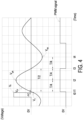
- FIG. 4 is a schematic timing waveform diagram illustrating the PWM signal from the zero-crossing detection circuit.
- FIG. 5 is a schematic circuit diagram illustrating the peak value detection circuit in the parameter acquisition unit of the detection unit as shown in FIG. 1B .
- the detection unit 3 includes a parameter acquisition unit 30 and a microprocessor 31.
- the parameter acquisition unit 30 is electrically coupled with the resonant circuit 22.
- the parameter acquisition unit 30 is electrically coupled with the first terminal of the resonant tank capacitor C r .
- the parameter acquisition unit 30 detects the capacitor voltage V cr of the resonant tank capacitor C r .
- the parameter acquisition unit 30 acquires the information about the resonant period T of the resonant tank 21 and the negative peak current value V np of the capacitor voltage V cr according to the capacitor voltage Ver.
- the parameter acquisition unit 30 can be implemented with a hardware component or a software component. In the embodiment of FIG. 1B , the parameter acquisition unit 30 is implemented with a hardware component. In addition, the parameter acquisition unit 30 includes a zero-crossing detection circuit 300 and a peak value detection circuit 301.
- the zero-crossing detection circuit 300 is electrically coupled with the resonant tank 21.
- the zero-crossing detection circuit 300 is electrically coupled with the first terminal of the resonant tank capacitor C r .
- the zero-crossing detection circuit 300 detects the capacitor voltage V cr of the resonant tank capacitor C r .
- the zero-crossing detection circuit 300 acquires the information about the resonant period T according to the capacitor voltage V cr of the resonant tank capacitor C r .
- the zero-crossing detection circuit 300 includes a first resistor R 1 , a second resistor R 2 , a comparator COM, a third resistor R 3 , a first capacitor C 1 and a Zener diode D z .
- the first terminal of the first resistor R 1 is electrically coupled with the first terminal of the resonant tank capacitor C r .
- the first terminal of the second resistor R 2 is electrically connected with the second terminal of the first resistor R 1 .
- the voltage across the first terminal of the first resistor R 1 and the second terminal of the second resistor R 2 is equal to the capacitor voltage V cr .
- the positive input terminal of the comparator COM is electrically coupled with the second terminal of the first resistor R 1 and the first terminal of the second resistor R 2 .
- the negative input terminal of the comparator COM is electrically coupled with the second terminal of the second resistor R 2 and a ground terminal G.
- the third resistor R 3 is electrically coupled between a voltage source V 2 (i.e., power source) and the output terminal of the comparator COM.
- the anode of the Zener diode D z is electrically coupled with the ground terminal G.
- the cathode of the Zener diode D z is electrically coupled with the output terminal of the comparator COM.
- the first capacitor C 1 is electrically connected between the output terminal of the comparator COM and the ground terminal G. In addition, the first capacitor C 1 and the Zener diode D z are electrically connected with each other in parallel.
- a pulse width modulation (PWM) signal is outputted from the comparator COM.
- the PWM signal is switched from the high level state to the low level state or switched from the low level state to the high level state.
- the time interval between the first zero-crossing time point and the second zero-crossing time point is equal to a half of the resonant period T.
- the resonant period T is equal to twice the time interval between the first zero-crossing time point and the second zero-crossing time point. Consequently, the resonant period T is defined by the capacitor voltage V cr , and the zero-crossing detection circuit 300 acquires information about the resonant period T according to the capacitor voltage V cr .
- the peak value detection circuit 301 is electrically coupled with the resonant tank 21.
- the peak value detection circuit 301 is electrically coupled with the first terminal of the resonant tank capacitor C r .
- the peak value detection circuit 301 detects the capacitor voltage V cr .
- the peak value detection circuit 301 acquires the information about the peak voltage value (i.e., the positive peak voltage value V pk and/or negative peak voltage value V np ) of the capacitor voltage V cr according to the capacitor voltage V cr .
- the peak value detection circuit 301 includes a fourth resistor R 4 , a fifth resistor R 5 , a sixth resistor R 6 , a negative feedback amplifier C amp , a diode D and a second capacitor C 2 .
- the first terminal of the fourth resistor R 4 is electrically coupled with the first terminal of the resonant tank capacitor C r .
- the first terminal of the fifth resistor R 5 is electrically connected with the second terminal of the fourth resistor R 4 .
- the voltage across the first terminal of the fourth resistor R 4 and the second terminal of the fifth resistor R 5 is equal to the capacitor voltage V cr .
- the non-inverting input terminal of the negative feedback amplifier C amp is electrically coupled with the second terminal of the fourth resistor R 4 and the first terminal of the fifth resistor R 5 .
- the inverting input terminal of the negative feedback amplifier C amp is electrically coupled with the output terminal of the negative feedback amplifier C amp .
- the anode of the diode D is electrically coupled with the output terminal of the negative feedback amplifier C amp .
- the sixth resistor R 6 is electrically connected between the cathode of the diode D and the ground terminal G.
- the second capacitor C 2 is electrically connected between the cathode of the diode D and the ground terminal G.
- the second capacitor C 2 and the sixth resistor R 6 are electrically coupled with each other in parallel.
- the peak value detection circuit 301 acquires the information about the positive peak voltage value V pk and/ or the negative peak voltage value V np of the capacitor voltage V cr according to the capacitor voltage V cr .
- the peak value detection circuit 301 acquires the information about the resonant period T, the positive peak voltage value V pk and/ or the negative peak voltage value V np of the capacitor voltage V cr according to the capacitor voltage V cr .
- the microprocessor 31 is a digital signal processor (DSP) or a microcontroller unit (MCU).
- DSP digital signal processor
- MCU microcontroller unit
- the microprocessor 31 is electrically coupled with the parameter acquisition unit 30.
- the microprocessor 31 includes a first calculation unit 310 and a second calculation unit 311.
- the first expression is previously stored in the first calculation unit 310.
- the first calculation unit 310 acquires the parameter information about the resonant period T from the parameter acquisition unit 30.
- the first calculation unit 310 calculates the inductance of the resonant tank equivalent inductor L est according to the capacitance of the resonant tank capacitor C r , the first expression and the received resonant period T. In addition, the first calculation unit 310 provides a first calculation result about the inductance of the resonant tank equivalent inductor Lest.
- the second expression is previously stored in the second calculation unit 311.
- the second calculation unit 311 acquires the first calculation result about the inductance of the resonant tank equivalent inductor L est from the first calculation unit 310.
- the second calculation unit 311 acquires the information about the reference voltage value V 1 , the time change value ⁇ t and the negative peak voltage value V np of the capacitor voltage V cr according to the capacitor voltage V cr .
- the second calculation unit 311 calculates the resistance of the resonant tank equivalent resistor R est according to the inductance of the resonant tank equivalent inductor L est , the reference voltage value V 1 , the time change value ⁇ t, the negative peak voltage value V np of the capacitor voltage V cr and the second expression.
- the second calculation unit 311 provides a second calculation result about the resistance of the resonant tank equivalent resistor R est .
- the detection unit 3 calculates the resistance of the resonant tank equivalent resistor R est according to the inductance of the resonant tank equivalent inductor L est , the time change value ⁇ t, the resonant period T, the reference voltage value V 1 , the positive peak voltage value V pk and a third expression.
- V pk is the positive peak voltage value.
- the third expression is previously stored in the second calculation unit 311.
- the second calculation unit 311 acquires the first calculation result about the inductance of the resonant tank equivalent inductor L est from the first calculation unit 310.
- the second calculation unit 311 acquires the information about the reference voltage value V 1 , the time change value ⁇ t and the positive peak voltage value V pk of the capacitor voltage V cr according to the capacitor voltage V cr .
- the second calculation unit 311 calculates the resistance of the resonant tank equivalent resistor R est according to the inductance of the resonant tank equivalent inductor L est , the reference voltage value V 1 , the time change value ⁇ t, the positive peak voltage value V pk of the capacitor voltage V cr and the third expression.
- the second calculation unit 311 provides the second calculation result about the resistance of the resonant tank equivalent resistor R est .
- the detection unit 3 calculates the resistance of the resonant tank equivalent resistor R est according to the inductance of the resonant tank equivalent inductor L est , the time change value ⁇ t, the resonant period T, the reference voltage value V 1 , the negative peak voltage value V np , the positive peak voltage value V pk and a fourth expression.
- the fourth expression is previously stored in the second calculation unit 311.
- the second calculation unit 311 acquires the first calculation result about the inductance of the resonant tank equivalent inductor L est from the first calculation unit 310.
- the second calculation unit 311 acquires the information about the reference voltage value V 1 , the time change value ⁇ t, the negative peak voltage value V np and the positive peak voltage value V pk of the capacitor voltage V cr according to the capacitor voltage V cr .
- the second calculation unit 311 calculates the resistance of the resonant tank equivalent resistor R est according to the inductance of the resonant tank equivalent inductor L est , the reference voltage value V 1 , the time change value ⁇ t, the negative peak voltage value V np and the positive peak voltage value V pk of the capacitor voltage V cr and the fourth expression. In addition, the second calculation unit 311 provides the second calculation result about the resistance of the resonant tank equivalent resistor R est .
- the control unit 4 of the heating device 1 acquires the resonant tank equivalent inductor L est and the resonant tank equivalent resistor R est according to the first calculation result and the second calculation result from the microprocessor 31. Furthermore, the control unit 4 performs various control operations on the resonant circuit 22 according to the resonant tank equivalent inductor L est and the resonant tank equivalent resistor R est . For example, according to the inductance of the resonant tank equivalent inductor L est and the resistance of the resonant tank equivalent resistor R est , the control unit 4 can determine whether the heating coil 210 is enabled or disabled and determine whether the foodstuff container is placed on the heating device 1.
- control unit 4 determines the burden ratio of the heating power of the heating coil 210 according to the inductance of the resonant tank equivalent inductor L est and the resistance of the resonant tank equivalent resistor R est . Also, the output power from the heating device 1 is corrected by the control unit 4 in real time according to the changes of the parameter values of the resonant tank equivalent inductor L est and the resonant tank equivalent resistor R est . Moreover, the control unit 4 can recognize the material of the foodstuff container according to the parameter values of the resonant tank equivalent inductor L est and the resonant tank equivalent resistor R est .
- the first expression (1), the second expression (2), the third expression (3) and the fourth expression (4) will be roughly derived with reference to FIGS. 1A , 1B , 2 and 3 .
- V cr (t) is a function of time of the capacitor voltage V cr
- ⁇ is an attenuation coefficient
- ⁇ d is a damping resonance frequency
- B 1 and B 2 are arbitrary constants determined by the boundary conditions. Since the heating device 1 is an induction cooking stove, ⁇ o 2 >> ⁇ 2 . Under this circumstance, the resonant tank 21 is operated in an underdamped zone.
- V p is the voltage peak value when the resonant tank 21 is in the natural resonance state
- ⁇ is the angle
- the mathematic formula (1) may be derived from the mathematic formula (7).
- the zero-crossing detection circuit 300 can be used to obtain the half resonant period T/2. After the half resonant period T/2 is introduced into the mathematic formula (1) according to the mathematic formula (9), the first calculation unit 310 acquires the inductance of the resonant tank equivalent inductor Lest.
- the magnitude of the capacitor voltage V cr is zero at sin0° and sin ⁇ . Consequently, the zero-crossing point of the capacitor voltage V cr is taken as the reference point, the calculation is carried out in the form of the relative angle.
- the instantaneous voltage value of the capacitor voltage V cr is served as the reference voltage value V 1 . That is, at the time point t0, the upper switch Q h is turned off, and the lower switch Q l is turned on.
- the first zero-crossing time point is the time point corresponding to the first zero value of the capacitor voltage V cr after the lower switch Q l is switched from the off state to the on state (e.g., at the time point 11).
- the time point t1 corresponds to the angle 0°.
- the positive peak voltage value V pk of the capacitor voltage V cr occurs at the time point t2 corresponding to the angle ⁇ /2.
- the negative peak voltage value V np of the capacitor voltage V cr occurs at the time point t4 corresponding to the angle 3 ⁇ /2.
- the sampling time point of the reference voltage value V 1 is obtained at the time point when the time change value ⁇ t is subtracted from the first zero-crossing time point of the capacitor voltage V cr .
- the positive peak voltage value V pk of the capacitor voltage V cr occurs at the time point t2 corresponding to the angle ⁇ /2
- the negative peak voltage value V np of the capacitor voltage V cr occurs at the time point t4 corresponding to the angle 3 ⁇ /2. Consequently, the following mathematic formulae (13), (14), (15), (16) and (17) can be obtained.
- the third expression for obtaining the resonant tank equivalent resistor R est can be derived from the mathematic formula (10) and (11).
- the second expression for obtaining the resonant tank equivalent resistor R est can be derived from the mathematic formula (10) and (12).
- the fourth expression for obtaining the resonant tank equivalent resistor R est can be derived from the mathematic formula (11) and (12).
- the general formula of the resonant tank equivalent resistor R est is the second expression (2).
- the general formula of the resonant tank equivalent resistor R est is the third expression (3).
- the general formula of the resonant tank equivalent resistor R est is the fourth expression (4).
- the detection unit 3 is implemented with a controller.
- the inverter circuit 20 includes the upper switch Q h and the lower switch Qi. It is noted that numerous modifications and alterations may be made while retaining the teachings of the invention. In some other embodiments, the inverter circuit 20 includes a single switch or at least four switches. In case that the inverter circuit 20 includes a single switch, the first terminal T 1 and the second terminal T 2 of the resonant tank 21 are electrically connected with the first conducting terminal and the second conducting terminal of the switch, respectively.
- the inverter circuit 20 includes four switches and the inverter circuit 20 is formed as a full-bridge inverter circuit, the first terminal T 1 and the second terminal T 2 of the resonant tank 21 are electrically coupled with the lower switch of each of the two bridge arms of the inverter circuit 20.
- the inverter circuit 20 includes a single switch or at least four switches, the operations of the heating device are similar to the those of the heating device 1, and not redundantly described herein.
- FIG. 6 is a flowchart illustrating a detecting method for a heating device according to an embodiment of the present disclosure.
- the detecting method is applied to the detection unit 3 of the heating device 1 as shown in FIG. 1B .
- the detecting method includes the following steps.
- the detection unit 3 acquires the information about the reference voltage value V 1 , the time change value ⁇ t, the first zero-crossing time point, the second zero-crossing time point, the resonant period T, the negative peak voltage value V np and the positive peak voltage value V pk according to the capacitor voltage V cr of the resonant tank capacitor C r .
- the detection unit 3 calculates the inductance of the resonant tank equivalent inductor L est according to the capacitance of the resonant tank capacitor C r , the resonant period T and the first expression.
- the detection unit 3 calculates the resistance of the resonant tank equivalent resistor R est according to the inductance of the resonant tank equivalent inductor L est , the time change value ⁇ t, the resonant period T, the reference voltage value V 1 , the negative peak voltage value V np , the positive peak voltage value V pk and one of the second expression, the third expression and the fourth expression.
- control unit 4 controls the heating power of the heating coil 210 according to the inductance of the resonant tank equivalent inductor L est and the resistance of the resonant tank equivalent resistor R est .
- the control unit 4 performs various control operations. For example, the control unit 4 determines whether the foodstuff container is placed on the heating device 1 according to the resonant tank equivalent inductor L est and the resonant tank equivalent resistor R est . Moreover, the control unit 4 determines the burden ratio of the heating coil 210 according to the inductance of the resonant tank equivalent inductor L est and the resistance of the resonant tank equivalent resistor R est . Moreover, the control unit 4 recognizes the material of the foodstuff container on the heating device 1 according to the inductance of the resonant tank equivalent inductor L esst and the resistance of the resonant tank equivalent resistor R est .
- the present disclosure provides the heating device and the detecting method for the heating device.
- the heating device includes the resonant tank.
- the main working principle of the present disclosure is based on the natural response characteristics of the resonant tank in the negative half cycle.
- the inductance of the resonant tank equivalent inductor is calculated according to the capacitor voltage of the resonant tank capacitor and the first expression.
- the resistance of the resonant tank equivalent resistor is calculated according to the inductance of the resonant tank equivalent inductor and one of the second expression, the third expression and the fourth expression.
- the detection circuit of the heating device of the present disclosure is simplified and the cost is reduced. Since it is not necessary to detect the current information about the resonant tank, the heating device is not equipped with the current detection circuit. In other words, the heating device of the present disclosure is cost-effective.
Landscapes
- Physics & Mathematics (AREA)
- Electromagnetism (AREA)
- Engineering & Computer Science (AREA)
- General Physics & Mathematics (AREA)
- Chemical & Material Sciences (AREA)
- Combustion & Propulsion (AREA)
- Mechanical Engineering (AREA)
- General Engineering & Computer Science (AREA)
- Induction Heating Cooking Devices (AREA)
- Inverter Devices (AREA)
Abstract
A heating device (1) includes a resonant circuit (22), a detection unit (3) and a control unit (4). The resonant circuit (22) includes an inverter circuit (20) and a resonant tank (21). The inverter circuit (20) provides a resonant tank current (I<sub>r</sub>) and a resonant tank voltage (V<sub>r</sub>). The resonant tank (21) includes a heating coil (210), a resonant tank capacitor (C<sub>r</sub>), a resonant tank equivalent inductor (L<sub>est</sub>) and a resonant tank equivalent resistor (R<sub>est</sub>). The detection unit (3) calculates an inductance of the resonant tank equivalent inductor (L<sub>est</sub>) according to a capacitance of the resonant tank capacitor (C<sub>r</sub>), a resonant period (T) and a first expression. The detection unit (3) calculates a resistance of the resonant tank equivalent resistor (R<sub>est</sub>) according to the inductance of the resonant tank equivalent inductor (L<sub>est</sub>), a time change value (Δt), a reference voltage value (V<sub>1</sub>), a negative peak voltage value (V<sub>np</sub>) and a second expression.
Description
- The present disclosure relates to a heating device, and more particularly to a heating device with a resonant tank and a detecting method thereof.
- Nowadays, a variety of heating devices such as gas stoves, infrared oven, microwave oven and electric stove are widely used to cook food. Different heating devices have their advantages or disadvantages. Depending on the food to be cooked, a desired heating device is selected.
- Take an induction cooking stove as an example of the heating device. When a current flows through the induction coil (or a heating coil) of the induction cooking stove, electromagnetic induction is performed to produce eddy current, thereby heating a foodstuff container. By adjusting electricity to the induction coil, the heat quantity for heating the foodstuff container is determined. Depending on the location of the foodstuff container relative to the induction coil and the material of the foodstuff container, the heat quantity for heating the foodstuff container by the induction coil and the operating condition and the current magnitude of the induction coil are varied. Generally, in case that the locations of the foodstuff containers or the materials of the foodstuff containers are different, different equivalent parameters are sensed by a resonant tank of the conventional induction cooking stove. In accordance with a conventional technology, the resonant tank equivalent resistance and the resonant tank equivalent inductance are calculated according to the resonant tank voltage, the resonant tank current and the phase difference between the resonant tank voltage and the resonant tank current. According to the calculation results of the resonant tank equivalent resistance and the resonant tank equivalent inductance, the electric power of the induction coil is adjusted. However, the conventional technology still has some drawbacks. For example, the conventional heating device needs to be additionally equipped with a voltage detection circuit and a current detection circuit. Consequently, the circuitry topology of the conventional heating device is complicated, and the fabricating cost is high.
- Therefore, there is a need of providing an improved heating device and a suitable detecting method in order to overcome the drawbacks of the conventional technologies.
- The present disclosure provides a heating device and a detecting method for the heating device. The heating device includes a resonant tank. The main working principle of the present disclosure is based on the natural response characteristics of the resonant tank in the negative half cycle. The inductance of the resonant tank equivalent inductor and the resistance of the resonant tank equivalent resistor are calculated according to the voltage information of the resonant tank. In other words, the current detection circuit can be omitted. When compared with the conventional heating device, the detection circuit of the heating device of the present disclosure is simplified and the cost is reduced.
- In accordance with an aspect of present disclosure, a heating device is provided. The heating device includes a resonant circuit, a detection unit and a control unit. The resonant circuit includes an inverter circuit and a resonant tank. The inverter circuit provides a resonant tank current and a resonant tank voltage. The resonant tank includes a heating coil, a resonant tank capacitor, a resonant tank equivalent inductor and a resonant tank equivalent resistor. The detection unit is electrically coupled with the resonant circuit. The detection unit detects a capacitor voltage of the resonant tank capacitor to acquire a reference voltage value, a first zero-crossing time point, a second zero-crossing time point, a time change value, a resonant period and a negative peak current value. The reference voltage value is a voltage value of the capacitor voltage when the resonant tank voltage is zero, the time change value is a time length between a time point when the resonant tank voltage is zero and the first zero-crossing time point. The resonant period is defined according to the first zero-crossing time point and the second zero-crossing time point. The control unit controls the inverter circuit to output the resonant tank current and the resonant tank voltage. Consequently, a heating power of the heating coil is adjustable. The detection unit calculates an inductance of the resonant tank equivalent inductor according to a capacitance of the resonant tank capacitor, the resonant period and a first expression. The detection unit calculates a resistance of the resonant tank equivalent resistor according to the inductance of the resonant tank equivalent inductor, the time change value, the resonant period, the reference voltage value, the negative peak voltage value and a second expression. The control unit controls the heating power of the heating coil according to the inductance of the resonant tank equivalent inductor and the resistance of the resonant tank equivalent resistor. The first expression is expressed as a following mathematic formula:


- In accordance with another aspect of present disclosure, a detecting method for a detection unit of a heating device is provided. The heating device further includes a resonant circuit. The resonant circuit includes an inverter circuit and a resonant tank. The inverter circuit provides a resonant tank current and a resonant tank voltage. The resonant tank includes a heating coil, a resonant tank capacitor, a resonant tank equivalent inductor and a resonant tank equivalent resistor. The detecting method includes the steps of:
- (a) detecting a capacitor voltage of the resonant tank capacitor to acquire a reference voltage value, a first zero-crossing time point, a second zero-crossing time point, a time change value, a resonant period, a negative peak voltage value and a positive peak voltage value, wherein the reference voltage value is a voltage value of the capacitor voltage when the resonant tank voltage is zero, the time change value is a time length between a time point when the resonant tank voltage is zero and the first zero-crossing time point, and the resonant period is defined according to the first zero-crossing time point and the second zero-crossing time point;
- (b) calculating an inductance of the resonant tank equivalent inductor according to a capacitance of the resonant tank capacitor, the resonant period and a first expression, wherein the first expression is expressed as a following mathematic formula:

- (c) calculating a resistance of the resonant tank equivalent resistor according to the inductance of the resonant tank equivalent inductor, the time change value, the resonant period, the reference voltage value, the negative peak voltage value, the positive peak voltage value and one of a second expression, a third expression and a fourth expression, wherein the second expression is expressed as a following mathematic formula:


- (d) controlling a heating power of the heating coil according to the inductance of the resonant tank equivalent inductor and the resistance of the resonant tank equivalent resistor.
- In accordance with another aspect of present disclosure, a heating device is provided. The heating device includes a resonant circuit, a detection unit and a control unit. The resonant circuit includes an inverter circuit and a resonant tank. The inverter circuit provides a resonant tank current and a resonant tank voltage. The resonant tank includes a heating coil, a resonant tank capacitor, a resonant tank equivalent inductor and a resonant tank equivalent resistor. The resonant circuit includes an inverter circuit and a resonant tank. The inverter circuit provides a resonant tank current and a resonant tank voltage. The resonant tank includes a heating coil, a resonant tank capacitor, a resonant tank equivalent inductor and a resonant tank equivalent resistor. The detection unit is electrically coupled with the resonant circuit. The detection unit detects a capacitor voltage of the resonant tank capacitor to acquire a reference voltage value, a first zero-crossing time point, a second zero-crossing time point, a time change value, a resonant period and a peak voltage value. The peak voltage value includes at least one of a negative peak voltage value and a positive peak voltage value. The reference voltage value is a voltage value of the capacitor voltage when the resonant tank voltage is zero. The time change value is a time length between a time point when the resonant tank voltage is zero and the first zero-crossing time point. The resonant period is defined according to the first zero-crossing time point and the second zero-crossing time point. The control unit controls the inverter circuit to output the resonant tank current and the resonant tank voltage. Consequently, a heating power of the heating coil is adjustable.
- The detection unit calculates an inductance of the resonant tank equivalent inductor according to a capacitance of the resonant tank capacitor, the resonant period and a first expression. The detection unit calculates a resistance of the resonant tank equivalent resistor according to the inductance of the resonant tank equivalent inductor, the time change value, the resonant period, the reference voltage value, the peak voltage value and one of a second expression, a third expression and a third expression. The control unit controls the heating power of the heating coil according to the inductance of the resonant tank equivalent inductor and the resistance of the resonant tank equivalent resistor. The first expression is expressed as a following mathematic formula:


- The above contents of the present disclosure will become more readily apparent to those ordinarily skilled in the art after reviewing the following detailed description and accompanying drawings, in which:
-
-
FIG. 1A is a schematic functional block diagram illustrating the architecture of a heating device according to an embodiment of the present disclosure; -
FIG. 1B is schematic circuit diagram illustrating the heating device as shown inFIG. 1A ; -
FIG. 2 is a schematic timing waveform diagram illustrating the resonant tank voltage and the capacitor voltage in the heating device ofFIG. 1B ; -
FIG. 3 is a schematic circuit diagram illustrating the zero-crossing detection circuit in the parameter acquisition unit of the detection unit as shown inFIG. 1B ; -
FIG. 4 is a schematic timing waveform diagram illustrating the PWM signal from the zero-crossing detection circuit; -
FIG. 5 is a schematic circuit diagram illustrating the peak value detection circuit in the parameter acquisition unit of the detection unit as shown inFIG. 1B ; and -
FIG. 6 is a flowchart illustrating a detecting method for a heating device according to an embodiment of the present disclosure. - The present disclosure will now be described more specifically with reference to the following embodiments. It is to be noted that the following descriptions of preferred embodiments of this invention are presented herein for purpose of illustration and description only. It is not intended to be exhaustive or to be limited to the precise form disclosed.
- Please refer to
FIGS. 1A ,1B and2 .FIG. 1A is a schematic functional block diagram illustrating the architecture of a heating device according to an embodiment of the present disclosure.FIG. 1B is schematic circuit diagram illustrating the heating device as shown inFIG. 1A .FIG. 2 is a schematic timing waveform diagram illustrating the resonant tank voltage and the capacitor voltage in the heating device ofFIG. 1B . Preferably but not exclusively, theheating device 1 is an induction cooking stove. Theheating device 1 includes apower supply circuit 2, adetection unit 3 and acontrol unit 4. - The
power supply circuit 2 includes aresonant circuit 22. Theresonant circuit 22 includes aninverter circuit 20 and aresonant tank 21. Theinverter circuit 20 receives an input voltage Vin. Theinverter circuit 20 includes at least one switch. For example, as shown inFIG. 1B , theinverter circuit 20 includes an upper switch Qh and a lower switch Qi. The upper switch Qh and the lower switch Qi are connected with each other in series. Consequently, theinverter circuit 20 is formed as a half-bridge inverter circuit. By alternately turning on and turning off the upper switch Qh and the lower switch Qi, the input voltage Vin is converted by theinverter circuit 20. Consequently, a resonant tank current Ir and a resonant tank voltage Vr are outputted from theinverter circuit 20. Moreover, each of the upper switch Qh and the lower switch Q1 includes a control terminal, a first conducting terminal and a second conducting terminal. - The
resonant tank 21 includes a first terminal T1, a second terminal Tz, aheating coil 210, a resonant tank capacitor Cr, a resonant tank equivalent inductor Lest and a resonant tank equivalent resistor Rest. The first terminal T1 and the second terminal T2 are respectively coupled with the two conducting terminals of one of the two switches of theinverter circuit 20. As shown inFIG. 1B , the first terminal T1 of theresonant tank 21 is electrically coupled with the first conducting terminal of the lower switch Ql, and the second terminal T2 of theresonant tank 21 is electrically coupled with the second conducting terminal of the lower switch Qi. The resonant tank capacitor Cr, the resonant tank equivalent inductor Lest and the resonant tank equivalent resistor Rest are serially connected between the first terminal T1 and the second terminal T2 in sequence. It is noted that the connection sequence of the resonant tank capacitor Cr, the resonant tank equivalent inductor Lest and the resonant tank equivalent resistor Rest between the first terminal T1 and the second terminal T2 is not restricted. The foodstuff container (not shown) on theheating device 1 is heated byheating coil 210 through induction according to the resonant tank current Ir and the resonant tank voltage Vr from the inverter current 20. Moreover, theresonant tank 21, theheating coil 210 and the foodstuff container are collaboratively equivalent to the resonant tank equivalent inductor Lest, and theresonant tank 21, theheating coil 210 and the foodstuff container are also equivalent to the resonant tank equivalent resistor Rest. In addition, the capacitance of the resonant tank capacitor Cr is a known value. - As mentioned above, the inductance of the resonant tank equivalent inductor Lest is related with the inductance of the
heating coil 210, the material of the foodstuff container and the location of the foodstuff container on theheating device 1. In other words, when the inductance of theheating coil 210, the material of the foodstuff container or the location of the foodstuff container on theheating device 1 is changed, the inductance of the resonant tank equivalent inductor Lest is correspondingly changed. Similarly, the resistance of the resonant tank equivalent resistor Rest is related with the resistance of theresonant tank 21, the material of the foodstuff container and the location of the foodstuff container on theheating device 1. In other words, when the resistance of theresonant circuit 22, the material of the foodstuff container or the location of the foodstuff container on theheating device 1 is changed, the resistance of the resonant tank equivalent resistor Rest is changed. - The
control unit 4 is electrically coupled with theinverter circuit 20. Thecontrol unit 4 controls theinverter circuit 20 to output the resonant tank current Ir and the resonant tank voltage Vr to theresonant tank 21. Consequently, the heating power of theheating coil 210 is controlled. - The
detection unit 3 is electrically coupled with theresonant circuit 22. For example, thedetection unit 3 is electrically coupled with a first terminal of the resonant tank capacitor Cr. Moreover, thedetection unit 3 detects a capacitor voltage Vcr of the resonant tank capacitor Cr to acquire the information about a reference voltage value V1, a time change value Δt, a first zero-crossing time point, a second zero-crossing time point, a resonant period T and a peak voltage value of the capacitor voltage Vcr. The peak voltage value is the maximum voltage (i.e., the positive peak voltage value Vpk) when the capacitor voltage Vcr is positive (e.g., at the time point t2 shown inFIG. 2 ), or the peak voltage value is the maximum voltage (i.e., the negative peak voltage value Vnp) when the capacitor voltage Vcr is negative (e.g., at the time point t4 shown inFIG. 2 ). In the following example, thedetection unit 3 detects the capacitor voltage Vcr of the resonant tank capacitor Cr to obtain the negative peak voltage value Vnp of the capacitor voltage Vcr. - The reference voltage value V1 is the voltage value of the capacitor voltage Vcr at the instant when the resonance tank voltage Vr becomes zero. For example, when the lower switch Ql of the
inverter circuit 20 is operated in the negative half cycle and switched from the off state to the on state and the resonant tank voltage Vr is zero (e.g., at the time point t0), the instantaneous voltage value of the capacitor voltage Vcr is served as the reference voltage value V1. The first zero-crossing time point is the time point corresponding to the first zero value of the capacitor voltage Vcr after the resonant tank voltage Vr is zero (e.g., at the time point 11). The second zero-crossing time point is the time point corresponding to the second zero value of the capacitor voltage Vcr after the resonant tank voltage Vr is zero (e.g., at the time point t3). The time change value Δt is a time length between the time point t0 (i.e., the time point when the resonant tank voltage Vr is zero) and the time point t1 (i.e., the time point corresponding to the first zero-crossing time point). The resonant period T is defined by the first zero-crossing time point and the second zero-crossing time point. The negative peak voltage Vnp is the maximum value of the capacitor voltage Vcr when the capacitor voltage Vcr is negative (i.e., at the time point t4). - In an embodiment, the
detection unit 3 calculates the inductance of the resonant tank equivalent inductor Lest according to the capacitance of the resonant tank capacitor Cr, a first expression and the resonant period T. The first expression is expressed as the following mathematic formula (1):
- In the above mathematic formula, Lest is the inductance of the resonant tank equivalent inductor, Cr is the capacitance of the resonant tank capacitor, and T is the resonant period.
- Moreover, the
detection unit 3 calculates the resistance of the resonant tank equivalent resistor Rest according to the inductance of the resonant tank equivalent inductor Lest, the time change value Δt, the resonant period T, the reference voltage value V1, the negative peak voltage value Vnp and a second expression. The second expression is expressed as the following mathematic formula (2):
- In the above mathematic formula, Rest is the resistance of the resonant tank equivalent resistor Rest, V1 is the reference voltage value, Δt is the time change value, and Vnp is the negative peak voltage value.
- Please refer to
FIGS. 1A ,1B ,2 ,3 ,4 and5 .FIG. 3 is a schematic circuit diagram illustrating the zero-crossing detection circuit in the parameter acquisition unit of the detection unit as shown inFIG. 1B .FIG. 4 is a schematic timing waveform diagram illustrating the PWM signal from the zero-crossing detection circuit.FIG. 5 is a schematic circuit diagram illustrating the peak value detection circuit in the parameter acquisition unit of the detection unit as shown inFIG. 1B . - The
detection unit 3 includes aparameter acquisition unit 30 and amicroprocessor 31. Theparameter acquisition unit 30 is electrically coupled with theresonant circuit 22. For example, theparameter acquisition unit 30 is electrically coupled with the first terminal of the resonant tank capacitor Cr. Theparameter acquisition unit 30 detects the capacitor voltage Vcr of the resonant tank capacitor Cr. When theinverter circuit 20 is operated in the negative half cycle and the resonant tank voltage Vr is zero (e.g., when the upper switch Qh of theinverter circuit 20 is operated in the negative half cycle and switched from the off state to the on state), theparameter acquisition unit 30 acquires the information about the resonant period T of theresonant tank 21 and the negative peak current value Vnp of the capacitor voltage Vcr according to the capacitor voltage Ver. - The
parameter acquisition unit 30 can be implemented with a hardware component or a software component. In the embodiment ofFIG. 1B , theparameter acquisition unit 30 is implemented with a hardware component. In addition, theparameter acquisition unit 30 includes a zero-crossingdetection circuit 300 and a peakvalue detection circuit 301. - The zero-crossing
detection circuit 300 is electrically coupled with theresonant tank 21. For example, the zero-crossingdetection circuit 300 is electrically coupled with the first terminal of the resonant tank capacitor Cr. The zero-crossingdetection circuit 300 detects the capacitor voltage Vcr of the resonant tank capacitor Cr. In addition, the zero-crossingdetection circuit 300 acquires the information about the resonant period T according to the capacitor voltage Vcr of the resonant tank capacitor Cr. - In an embodiment, the zero-crossing
detection circuit 300 includes a first resistor R1, a second resistor R2, a comparator COM, a third resistor R3, a first capacitor C1 and a Zener diode Dz. The first terminal of the first resistor R1 is electrically coupled with the first terminal of the resonant tank capacitor Cr. The first terminal of the second resistor R2 is electrically connected with the second terminal of the first resistor R1. In addition, the voltage across the first terminal of the first resistor R1 and the second terminal of the second resistor R2 is equal to the capacitor voltage Vcr. The positive input terminal of the comparator COM is electrically coupled with the second terminal of the first resistor R1 and the first terminal of the second resistor R2. The negative input terminal of the comparator COM is electrically coupled with the second terminal of the second resistor R2 and a ground terminal G. The third resistor R3 is electrically coupled between a voltage source V2 (i.e., power source) and the output terminal of the comparator COM. The anode of the Zener diode Dz is electrically coupled with the ground terminal G. The cathode of the Zener diode Dz is electrically coupled with the output terminal of the comparator COM. The first capacitor C1 is electrically connected between the output terminal of the comparator COM and the ground terminal G. In addition, the first capacitor C1 and the Zener diode Dz are electrically connected with each other in parallel. - Due to the hardware structure of the zero-crossing
detection circuit 300, a pulse width modulation (PWM) signal is outputted from the comparator COM. Whenever the capacitor voltage Vcr is zero (i.e., at the time point corresponding to the zero-crossing point), the PWM signal is switched from the high level state to the low level state or switched from the low level state to the high level state. After the lower switch Ql of theinverter circuit 20 is switched from the off state to the on state and the resonant tank voltage Vr is zero, the time interval between the first zero-crossing time point and the second zero-crossing time point is equal to a half of the resonant period T. In other words, the resonant period T is equal to twice the time interval between the first zero-crossing time point and the second zero-crossing time point. Consequently, the resonant period T is defined by the capacitor voltage Vcr, and the zero-crossingdetection circuit 300 acquires information about the resonant period T according to the capacitor voltage Vcr. - The peak
value detection circuit 301 is electrically coupled with theresonant tank 21. For example, the peakvalue detection circuit 301 is electrically coupled with the first terminal of the resonant tank capacitor Cr. The peakvalue detection circuit 301 detects the capacitor voltage Vcr. Moreover, the peakvalue detection circuit 301 acquires the information about the peak voltage value (i.e., the positive peak voltage value Vpk and/or negative peak voltage value Vnp) of the capacitor voltage Vcr according to the capacitor voltage Vcr. - In an embodiment, the peak
value detection circuit 301 includes a fourth resistor R4, a fifth resistor R5, a sixth resistor R6, a negative feedback amplifier Camp, a diode D and a second capacitor C2. The first terminal of the fourth resistor R4 is electrically coupled with the first terminal of the resonant tank capacitor Cr. The first terminal of the fifth resistor R5 is electrically connected with the second terminal of the fourth resistor R4. The voltage across the first terminal of the fourth resistor R4 and the second terminal of the fifth resistor R5 is equal to the capacitor voltage Vcr. The non-inverting input terminal of the negative feedback amplifier Camp is electrically coupled with the second terminal of the fourth resistor R4 and the first terminal of the fifth resistor R5. The inverting input terminal of the negative feedback amplifier Camp is electrically coupled with the output terminal of the negative feedback amplifier Camp. The anode of the diode D is electrically coupled with the output terminal of the negative feedback amplifier Camp. The sixth resistor R6 is electrically connected between the cathode of the diode D and the ground terminal G. The second capacitor C2 is electrically connected between the cathode of the diode D and the ground terminal G. In addition, the second capacitor C2 and the sixth resistor R6 are electrically coupled with each other in parallel. Due to the above circuitry topology of the peakvalue detection circuit 301, the peakvalue detection circuit 301 acquires the information about the positive peak voltage value Vpk and/ or the negative peak voltage value Vnp of the capacitor voltage Vcr according to the capacitor voltage Vcr. - In case that the
parameter acquisition unit 30 is implemented with a software component, an algorithm, a calculation formula and/or a parameter relationship table can be previously stored in theparameter acquisition unit 30. In the cooperation of the algorithm, the calculation formula and/or the parameter relationship table, the peakvalue detection circuit 301 acquires the information about the resonant period T, the positive peak voltage value Vpk and/ or the negative peak voltage value Vnp of the capacitor voltage Vcr according to the capacitor voltage Vcr. - Preferably but not exclusively, the
microprocessor 31 is a digital signal processor (DSP) or a microcontroller unit (MCU). Themicroprocessor 31 is electrically coupled with theparameter acquisition unit 30. In an embodiment, themicroprocessor 31 includes afirst calculation unit 310 and asecond calculation unit 311. - The first expression is previously stored in the
first calculation unit 310. Thefirst calculation unit 310 acquires the parameter information about the resonant period T from theparameter acquisition unit 30. - The
first calculation unit 310 calculates the inductance of the resonant tank equivalent inductor Lest according to the capacitance of the resonant tank capacitor Cr, the first expression and the received resonant period T. In addition, thefirst calculation unit 310 provides a first calculation result about the inductance of the resonant tank equivalent inductor Lest. - The second expression is previously stored in the
second calculation unit 311. Thesecond calculation unit 311 acquires the first calculation result about the inductance of the resonant tank equivalent inductor Lest from thefirst calculation unit 310. In addition, thesecond calculation unit 311 acquires the information about the reference voltage value V1, the time change value Δt and the negative peak voltage value Vnp of the capacitor voltage Vcr according to the capacitor voltage Vcr. Thesecond calculation unit 311 calculates the resistance of the resonant tank equivalent resistor Rest according to the inductance of the resonant tank equivalent inductor Lest, the reference voltage value V1, the time change value Δt, the negative peak voltage value Vnp of the capacitor voltage Vcr and the second expression. In addition, thesecond calculation unit 311 provides a second calculation result about the resistance of the resonant tank equivalent resistor Rest. - In some embodiments, the
detection unit 3 calculates the resistance of the resonant tank equivalent resistor Rest according to the inductance of the resonant tank equivalent inductor Lest, the time change value Δt, the resonant period T, the reference voltage value V1, the positive peak voltage value Vpk and a third expression. The third expression is expressed as a following mathematic formula:
- In the above mathematic formula, Vpk is the positive peak voltage value.
- The third expression is previously stored in the
second calculation unit 311. Thesecond calculation unit 311 acquires the first calculation result about the inductance of the resonant tank equivalent inductor Lest from thefirst calculation unit 310. Thesecond calculation unit 311 acquires the information about the reference voltage value V1, the time change value Δt and the positive peak voltage value Vpk of the capacitor voltage Vcr according to the capacitor voltage Vcr. In addition, thesecond calculation unit 311 calculates the resistance of the resonant tank equivalent resistor Rest according to the inductance of the resonant tank equivalent inductor Lest, the reference voltage value V1, the time change value Δt, the positive peak voltage value Vpk of the capacitor voltage Vcr and the third expression. In addition, thesecond calculation unit 311 provides the second calculation result about the resistance of the resonant tank equivalent resistor Rest. - In some embodiments, the
detection unit 3 calculates the resistance of the resonant tank equivalent resistor Rest according to the inductance of the resonant tank equivalent inductor Lest, the time change value Δt, the resonant period T, the reference voltage value V1, the negative peak voltage value Vnp, the positive peak voltage value Vpk and a fourth expression. The fourth expression is expressed as a following mathematic formula:
- Moreover, the fourth expression is previously stored in the
second calculation unit 311. Thesecond calculation unit 311 acquires the first calculation result about the inductance of the resonant tank equivalent inductor Lest from thefirst calculation unit 310. Thesecond calculation unit 311 acquires the information about the reference voltage value V1, the time change value Δt, the negative peak voltage value Vnp and the positive peak voltage value Vpk of the capacitor voltage Vcr according to the capacitor voltage Vcr. Thesecond calculation unit 311 calculates the resistance of the resonant tank equivalent resistor Rest according to the inductance of the resonant tank equivalent inductor Lest, the reference voltage value V1, the time change value Δt, the negative peak voltage value Vnp and the positive peak voltage value Vpk of the capacitor voltage Vcr and the fourth expression. In addition, thesecond calculation unit 311 provides the second calculation result about the resistance of the resonant tank equivalent resistor Rest. - In an embodiment, the
control unit 4 of theheating device 1 acquires the resonant tank equivalent inductor Lest and the resonant tank equivalent resistor Rest according to the first calculation result and the second calculation result from themicroprocessor 31. Furthermore, thecontrol unit 4 performs various control operations on theresonant circuit 22 according to the resonant tank equivalent inductor Lest and the resonant tank equivalent resistor Rest. For example, according to the inductance of the resonant tank equivalent inductor Lest and the resistance of the resonant tank equivalent resistor Rest, thecontrol unit 4 can determine whether theheating coil 210 is enabled or disabled and determine whether the foodstuff container is placed on theheating device 1. In addition, thecontrol unit 4 determines the burden ratio of the heating power of theheating coil 210 according to the inductance of the resonant tank equivalent inductor Lest and the resistance of the resonant tank equivalent resistor Rest. Also, the output power from theheating device 1 is corrected by thecontrol unit 4 in real time according to the changes of the parameter values of the resonant tank equivalent inductor Lest and the resonant tank equivalent resistor Rest. Moreover, thecontrol unit 4 can recognize the material of the foodstuff container according to the parameter values of the resonant tank equivalent inductor Lest and the resonant tank equivalent resistor Rest. - Hereinafter, the first expression (1), the second expression (2), the third expression (3) and the fourth expression (4) will be roughly derived with reference to
FIGS. 1A ,1B ,2 and3 . - The main working principle of the present disclosure is based on the natural response characteristics of the
resonant tank 21. After the time point t=t0 (i.e., t ≥ 0), the natural response of theresonant tank 21 occurs. Consequently, the general formula of the capacitor voltage Vcr can be expressed as the following mathematic formula (5):
- In the above mathematic formula, Vcr(t) is a function of time of the capacitor voltage Vcr, α is an attenuation coefficient, ωd is a damping resonance frequency, and B1 and B2 are arbitrary constants determined by the boundary conditions. Since the
heating device 1 is an induction cooking stove, ωo 2 >> α2. Under this circumstance, theresonant tank 21 is operated in an underdamped zone. The damping resonance frequency can be simplified as:

- In the above mathematic formula, Vp is the voltage peak value when the
resonant tank 21 is in the natural resonance state, and θ is the angle. - In the mathematic formula (6), some parameters may be expressed as the following general formulae:
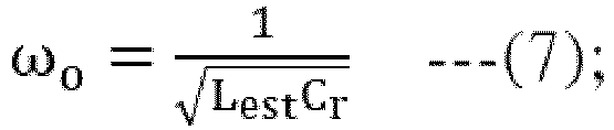

- Consequently, the mathematic formula (1) may be derived from the mathematic formula (7). In addition, the relationship between the resonance frequency fo and the resonant period T may be expressed as the following mathematic formula:

- Generally, in case that the duty cycle of the upper switch Qh is smaller, the discharge waveform of the
resonant tank 21 in the negative half cycle is relatively complete. Under this circumstance, the zero-crossingdetection circuit 300 can be used to obtain the half resonant period T/2. After the half resonant period T/2 is introduced into the mathematic formula (1) according to the mathematic formula (9), thefirst calculation unit 310 acquires the inductance of the resonant tank equivalent inductor Lest. - Moreover, the magnitude of the capacitor voltage Vcr is zero at sin0° and sinπ. Consequently, the zero-crossing point of the capacitor voltage Vcr is taken as the reference point, the calculation is carried out in the form of the relative angle. Please refer to
FIG. 2 again. For example, when the lower switch Ql is switched from the off state to the on state and the resonant tank voltage Vr is zero (e.g., at the time point t0), the instantaneous voltage value of the capacitor voltage Vcr is served as the reference voltage value V1. That is, at the time point t0, the upper switch Qh is turned off, and the lower switch Ql is turned on. The first zero-crossing time point is the time point corresponding to the first zero value of the capacitor voltage Vcr after the lower switch Ql is switched from the off state to the on state (e.g., at the time point 11). The time point t1 corresponds to the angle 0°. The positive peak voltage value Vpk of the capacitor voltage Vcr occurs at the time point t2 corresponding to the angle π/2. The negative peak voltage value Vnp of the capacitor voltage Vcr occurs at the time point t4 corresponding to the angle 3π/2. According to the mathematic formula (6), the relationship between the voltage peak value VP, the positive peak voltage value Vpk, the negative peak voltage value Vnp and the angle θ may be expressed as the mathematic formulae (10), (11) and (12):


- As shown in
FIG. 2 , the sampling time point of the reference voltage value V1 is obtained at the time point when the time change value Δt is subtracted from the first zero-crossing time point of the capacitor voltage Vcr. Moreover, the positive peak voltage value Vpk of the capacitor voltage Vcr occurs at the time point t2 corresponding to the angle π/2, and the negative peak voltage value Vnp of the capacitor voltage Vcr occurs at the time point t4 corresponding to the angle 3π/2. Consequently, the following mathematic formulae (13), (14), (15), (16) and (17) can be obtained.


- The third expression for obtaining the resonant tank equivalent resistor Rest can be derived from the mathematic formula (10) and (11).
- The second expression for obtaining the resonant tank equivalent resistor Rest can be derived from the mathematic formula (10) and (12).
- The fourth expression for obtaining the resonant tank equivalent resistor Rest can be derived from the mathematic formula (11) and (12).
- As mentioned above, in case that the
detection unit 3 detects the capacitor voltage Vcr of the resonant tank capacitor Cr to acquire the negative peak voltage value Vnp of the capacitor voltage Vcr, the general formula of the resonant tank equivalent resistor Rest is the second expression (2). In case that thedetection unit 3 detects the capacitor voltage Vcr of the resonant tank capacitor Cr to acquire the positive peak voltage value Vpk of the capacitor voltage Vcr, the general formula of the resonant tank equivalent resistor Rest is the third expression (3). In case that thedetection unit 3 detects the capacitor voltage Vcr of the resonant tank capacitor Cr to acquire the positive peak voltage value Vpk and the negative peak voltage value Vnp of the capacitor voltage Vcr, the general formula of the resonant tank equivalent resistor Rest is the fourth expression (4). - In an embodiment, the
detection unit 3 is implemented with a controller. - In the above embodiment, the
inverter circuit 20 includes the upper switch Qh and the lower switch Qi. It is noted that numerous modifications and alterations may be made while retaining the teachings of the invention. In some other embodiments, theinverter circuit 20 includes a single switch or at least four switches. In case that theinverter circuit 20 includes a single switch, the first terminal T1 and the second terminal T2 of theresonant tank 21 are electrically connected with the first conducting terminal and the second conducting terminal of the switch, respectively. In case that theinverter circuit 20 includes four switches and theinverter circuit 20 is formed as a full-bridge inverter circuit, the first terminal T1 and the second terminal T2 of theresonant tank 21 are electrically coupled with the lower switch of each of the two bridge arms of theinverter circuit 20. In case that theinverter circuit 20 includes a single switch or at least four switches, the operations of the heating device are similar to the those of theheating device 1, and not redundantly described herein. - Please refer to
FIG. 6. FIG. 6 is a flowchart illustrating a detecting method for a heating device according to an embodiment of the present disclosure. The detecting method is applied to thedetection unit 3 of theheating device 1 as shown inFIG. 1B . The detecting method includes the following steps. - In a step S1, the
detection unit 3 acquires the information about the reference voltage value V1, the time change value Δt, the first zero-crossing time point, the second zero-crossing time point, the resonant period T, the negative peak voltage value Vnp and the positive peak voltage value Vpk according to the capacitor voltage Vcr of the resonant tank capacitor Cr. - In a step S2, the
detection unit 3 calculates the inductance of the resonant tank equivalent inductor Lest according to the capacitance of the resonant tank capacitor Cr, the resonant period T and the first expression. - In a step S3, the
detection unit 3 calculates the resistance of the resonant tank equivalent resistor Rest according to the inductance of the resonant tank equivalent inductor Lest, the time change value Δt, the resonant period T, the reference voltage value V1, the negative peak voltage value Vnp, the positive peak voltage value Vpk and one of the second expression, the third expression and the fourth expression. - In a step S4, the
control unit 4 controls the heating power of theheating coil 210 according to the inductance of the resonant tank equivalent inductor Lest and the resistance of the resonant tank equivalent resistor Rest. - Furthermore, in the step S4, the
control unit 4 performs various control operations. For example, thecontrol unit 4 determines whether the foodstuff container is placed on theheating device 1 according to the resonant tank equivalent inductor Lest and the resonant tank equivalent resistor Rest. Moreover, thecontrol unit 4 determines the burden ratio of theheating coil 210 according to the inductance of the resonant tank equivalent inductor Lest and the resistance of the resonant tank equivalent resistor Rest. Moreover, thecontrol unit 4 recognizes the material of the foodstuff container on theheating device 1 according to the inductance of the resonant tank equivalent inductor Lesst and the resistance of the resonant tank equivalent resistor Rest. - From the above descriptions, the present disclosure provides the heating device and the detecting method for the heating device. The heating device includes the resonant tank. The main working principle of the present disclosure is based on the natural response characteristics of the resonant tank in the negative half cycle. The inductance of the resonant tank equivalent inductor is calculated according to the capacitor voltage of the resonant tank capacitor and the first expression. The resistance of the resonant tank equivalent resistor is calculated according to the inductance of the resonant tank equivalent inductor and one of the second expression, the third expression and the fourth expression. When compared with the conventional heating device, the detection circuit of the heating device of the present disclosure is simplified and the cost is reduced. Since it is not necessary to detect the current information about the resonant tank, the heating device is not equipped with the current detection circuit. In other words, the heating device of the present disclosure is cost-effective.
Claims (14)
- A heating device (1), characterized by comprising:a resonant circuit (22) comprising an inverter circuit (20) and a resonant tank (21), wherein the inverter circuit (20) provides a resonant tank current (Ir) and a resonant tank voltage (Vr), and the resonant tank (21) comprises a heating coil (210), a resonant tank capacitor (Cr), a resonant tank equivalent inductor (Lest) and a resonant tank equivalent resistor (Rest);a detection unit (3) electrically coupled with the resonant circuit (22), wherein the detection unit (3) detects a capacitor voltage (Vcr) of the resonant tank capacitor (Cr) to acquire a reference voltage value (V1), a first zero-crossing time point, a second zero-crossing time point, a time change value (Δt), a resonant period (T) and a negative peak current value (Vnp), wherein the reference voltage value (V1) is a voltage value of the capacitor voltage (Vcr) when the resonant tank voltage (Vr) is zero, the time change value (Δt) is a time length between a time point when the resonant tank voltage (Vr) is zero and the first zero-crossing time point, and the resonant period (T) is defined according to the first zero-crossing time point and the second zero-crossing time point; anda control unit (4) controlling the inverter circuit (20) to output the resonant tank current (Ir) and the resonant tank voltage (Vr), so that a heating power of the heating coil (210) is adjustable,wherein the detection unit (3) calculates an inductance of the resonant tank equivalent inductor (Lest) according to a capacitance of the resonant tank capacitor (Cr), the resonant period (T) and a first expression, the detection unit (3) calculates a resistance of the resonant tank equivalent resistor (Rest) according to the inductance of the resonant tank equivalent inductor (Lest), the time change value (Δt), the resonant period (T), the reference voltage value (V1), the negative peak voltage value (Vnp) and a second expression, and the control unit (4) controls the heating power of the heating coil (210) according to the inductance of the resonant tank equivalent inductor (Lest) and the resistance of the resonant tank equivalent resistor (Rest),wherein Lest is the inductance of the resonant tank equivalent inductor (Lest), Cr is the capacitance of the resonant tank capacitor (Cr), T is the resonant period (T), and the first expression is expressed as a following mathematic formula:
 wherein Rest is the resistance of the resonant tank equivalent resistor (Rest), V1 is the reference voltage value (V1), Δt is the time change value (Δt), Vnp is the negative peak voltage value (Vnp), and the second expression is expressed as a following mathematic formula:
- The heating device (1) according to claim 1, wherein the detection unit (3) comprises a parameter acquisition unit (30), and the parameter acquisition unit (30) is electrically coupled with the resonant tank (21) to detect the capacitor voltage (Vcr), wherein when the resonant tank voltage (Vr) is zero, the parameter acquisition unit (30) acquires the resonant period (T) according to the capacitor voltage (Vcr), and the parameter acquisition unit (30) acquires the negative peak voltage value (Vnp) or a positive peak voltage value (Vpk) of the capacitor voltage (Vcr) according to the capacitor voltage (Vcr).
- The heating device (1) according to claim 2, wherein the parameter acquisition unit (30) comprises:a zero-crossing detection circuit (300) electrically coupled with the resonant tank (21), wherein the zero-crossing detection circuit (300) detects the capacitor voltage (Vcr), and the zero-crossing detection circuit (300) acquires the resonant period (T) according to the capacitor voltage (Vcr); anda peak value detection circuit (301) electrically coupled with the resonant tank (21), wherein the peak value detection circuit (301) detects the capacitor voltage (Vcr), and the peak value detection circuit (301) acquires the negative peak voltage value (Vnp) or the positive peak voltage value (Vpk) according to the capacitor voltage (Vcr).
- The heating device (1) according to claim 3, wherein the zero-crossing detection circuit (300) comprises:a first resistor (R1), wherein a first terminal of the first resistor (R1) is electrically coupled with a first terminal of the resonant tank capacitor (Cr);a second resistor (R2), wherein a first terminal of the second resistor (R2) is electrically connected with a second terminal of the first resistor (R1), and a voltage difference between the first terminal of the first resistor (R1) and a second terminal of the second resistor (R2) is equal to the capacitor voltage (Vcr);a comparator (COM), wherein a positive input terminal of the comparator (COM) is electrically coupled with the second terminal of the first resistor (R1) and the first terminal of the second resistor (R2), and a negative input terminal of the comparator (COM) is electrically coupled with the second terminal of the second resistor (R2) and a ground terminal (G);a third resistor (R3) electrically connected between a power source (V2) and an output terminal of the comparator (COM);a Zener diode (Dz), wherein an anode of the Zener diode (Dz) is electrically coupled with the ground terminal (G), and a cathode of the Zener diode (Dz) is electrically coupled with the output terminal of the comparator (COM); anda first capacitor (C1) electrically connected between the output terminal of the comparator (COM) and the ground terminal (G), wherein the first capacitor (C1) and the Zener diode (Dz) are electrically connected with each other in parallel.
- The heating device (1) according to claim 3, wherein the peak value detection circuit (301) comprises:a fourth resistor (R4), wherein a first terminal of the fourth resistor (R4) is electrically coupled with a first terminal of the resonant tank capacitor (Cr);a fifth resistor (R5), wherein a first terminal of the fifth resistor (R5) is electrically connected with a second terminal of the fourth resistor (R4), and a voltage difference between the first terminal of the fourth resistor (R4) and a second terminal of the fifth resistor (R5) is equal to the capacitor voltage (Vcr);a negative feedback amplifier (Camp), wherein a non-inverting input terminal of the negative feedback amplifier (Camp) is electrically coupled with the second terminal of the fourth resistor (R4) and the first terminal of the fifth resistor (R5), and an inverting input terminal of the negative feedback amplifier (Camp) is electrically coupled with an output terminal of the negative feedback amplifier (Camp);a diode (D), wherein an anode of the diode (D) is electrically coupled with the output terminal of the negative feedback amplifier (Camp);a sixth resistor (R6) electrically connected between a cathode of the diode (D) and a ground terminal (G); anda second capacitor (C2) electrically connected between the cathode of the diode (D) and the ground terminal (G), wherein the second capacitor (C2) and the sixth resistor (R6) are electrically connected with each other in parallel.
- The heating device (1) according to claim 4, wherein the detection unit (3) further comprises a microprocessor (31), and the microprocessor (31) comprises:a first calculation unit (310), wherein the first expression is previously stored in the first calculation unit (310), and the first calculation unit (310) calculates the inductance of the resonant tank equivalent inductor (Lest) according to the capacitance of the resonant tank capacitor (Cr), the resonant period (T) provided by the zero-crossing detection circuit (300) and the first expression, and the first calculation unit (310) provides a first calculation result to the control unit (4); anda second calculation unit (320), wherein the second expression is previously stored in the second calculation unit (320), the second calculation unit (320) acquires the first calculation result from the first calculation unit (310), the second calculation unit (320) acquires the reference voltage value (V1), the time change value (Δt) and the negative peak voltage value (Vnp) of the capacitor voltage (Vcr) according to the capacitor voltage (Vcr), the second calculation unit (320) calculates the resistance of the resonant tank equivalent resistor (Rest) according to the inductance of the resonant tank equivalent inductor (Lest), the reference voltage value (V1), the time change value (Δt), the negative peak voltage value (Vnp) of the capacitor voltage (Vcr) and the second expression, and the second calculation unit (320) provides a second calculation result to the control unit (4).
- The heating device (1) according to claim 6, wherein the microprocessor (31) is a digital signal processor or a microcontroller unit.
- The heating device (1) according to claim 1, wherein the heating device (1) is an induction cooking stove.
- The heating device (1) according to claim 1, wherein the inverter circuit (20) comprises an upper switch (Qh) and a lower switch (Q1), which are connected with each other in series, wherein the upper switch (Qh) and the lower switch (Q1) are alternately turned on and turned off, and a first terminal and a second terminal of the resonant tank (21) are respectively coupled with two conducting terminals of the lower switch (Q1).
- A detecting method for a detection unit (3) of a heating device (1), the heating device (1) further comprising a resonant circuit (22), the resonant circuit (22) comprising an inverter circuit (20) and a resonant tank (21), the inverter circuit (20) providing a resonant tank current (Ir) and a resonant tank voltage (Vr), the resonant tank (21) comprising a heating coil (210), a resonant tank capacitor (Cr), a resonant tank equivalent inductor (Lest) and a resonant tank equivalent resistor (Rest), characterized in that the detecting method comprises steps of:(a) detecting a capacitor voltage (Vcr) of the resonant tank capacitor (Cr) to acquire a reference voltage value (V1), a first zero-crossing time point, a second zero-crossing time point, a time change value (Δt), a resonant period (T), a negative peak voltage value (Vnp) and a positive peak voltage value (Vpk), wherein the reference voltage value (V1) is a voltage value of the capacitor voltage (Vcr) when the resonant tank voltage (Vr) is zero, the time change value (Δt) is a time length between a time point when the resonant tank voltage (Vr) is zero and the first zero-crossing time point, and the resonant period (T) is defined according to the first zero-crossing time point and the second zero-crossing time point;(b) calculating an inductance of the resonant tank equivalent inductor (Lest) according to a capacitance of the resonant tank capacitor (Cr), the resonant period (T) and a first expression, wherein the first expression is expressed as a following mathematic formula:
 (c) calculating a resistance of the resonant tank equivalent resistor (Rest) according to the inductance of the resonant tank equivalent inductor (Lest), the time change value (Δt), the resonant period (T), the reference voltage value (V1), the negative peak voltage value (Vnp), the positive peak voltage value (Vpk) and one of a second expression, a third expression and a fourth expression, wherein the second expression is expressed as a following mathematic formula:

 (d) controlling a heating power of the heating coil (210) according to the inductance of the resonant tank equivalent inductor (Lest) and the resistance of the resonant tank equivalent resistor (Rest).
 - The detecting method according to claim 10, wherein the heating device (1) is an induction cooking stove, and the step (d) further comprises a step of determining whether a foodstuff container is placed on the heating device (1) according to the inductance of the resonant tank equivalent inductor (Lest) and the resistance of the resonant tank equivalent resistor (Rest).
- The detecting method according to claim 10, wherein the heating device (1) is an induction cooking stove, and the step (d) further comprises a step of determining a burden ratio of the heating coil (210) according to the inductance of the resonant tank equivalent inductor (Lest) and the resistance of the resonant tank equivalent resistor (Rest).
- The detecting method according to claim 10, wherein the heating device (1) is an induction cooking stove, and the step (d) further comprises a step of recognizing a material of a foodstuff container on the heating device (1) according to the inductance of the resonant tank equivalent inductor (Lest) and the resistance of the resonant tank equivalent resistor (Rest).
- A heating device (1), characterized by comprising:a resonant circuit (22) comprising an inverter circuit (20) and a resonant tank (21), wherein the inverter circuit (20) provides a resonant tank current (Ir) and a resonant tank voltage (Vr), and the resonant tank (21) comprises a heating coil (210), a resonant tank capacitor (Cr), a resonant tank equivalent inductor (Lest) and a resonant tank equivalent resistor (Rest);a detection unit (3) electrically coupled with the resonant circuit (22), wherein the detection unit (3) detects a capacitor voltage (Vcr) of the resonant tank capacitor (Cr) to acquire a reference voltage value (V1), a first zero-crossing time point, a second zero-crossing time point, a time change value (Δt), a resonant period (T) and a peak voltage value, wherein the peak voltage value includes at least one of a negative peak voltage value (Vnp) and a positive peak voltage value (Vpk), the reference voltage value is a voltage value of the capacitor voltage (Vcr) when the resonant tank voltage (Vr) is zero, the time change value (Δt) is a time length between a time point when the resonant tank voltage (Vr) is zero and the first zero-crossing time point, and the resonant period (T) is defined according to the first zero-crossing time point and the second zero-crossing time point; anda control unit (4) controlling the inverter circuit (20) to output the resonant tank current (Ir) and the resonant tank voltage (Vr), so that a heating power of the heating coil (210) is adjustable,wherein the detection unit (3) calculates an inductance of the resonant tank equivalent inductor (Lest) according to a capacitance of the resonant tank capacitor (Cr), the resonant period (T) and a first expression, the detection unit (3) calculates a resistance of the resonant tank equivalent resistor (Rest) according to the inductance of the resonant tank equivalent inductor (Lest), the time change value (Δt), the resonant period (T), the reference voltage value (V1), the peak voltage value and one of a second expression, a third expression and a third expression, and the control unit (4) controls the heating power of the heating coil (210) according to the inductance of the resonant tank equivalent inductor (Lest) and the resistance of the resonant tank equivalent resistor (Rest),wherein Lest is the inductance of the resonant tank equivalent inductor (Lest), Cr is the capacitance of the resonant tank capacitor (Cr), T is the resonant period (T), and the first expression is expressed as a following mathematic formula:
 wherein Rest is the resistance of the resonant tank equivalent resistor (Rest), V1 is the reference voltage value (V1), Δt is the time change value (Δt), Vnp is the negative peak voltage value (Vnp), and the second expression is expressed as a following mathematic formula:
 wherein Vpk is the positive peak voltage value (Vpk), and the third expression is expressed as a following mathematic formula:
 wherein Vpk is the positive peak voltage value (Vpk), Vnp is the negative peak voltage value (Vnp), and the fourth expression is expressed as a following mathematic formula:
Applications Claiming Priority (1)
| Application Number | Priority Date | Filing Date | Title |
|---|---|---|---|
| CN202311006469.1A CN119485818B (en) | 2023-08-10 | 2023-08-10 | Heating device and applicable detection method thereof |
Publications (1)
| Publication Number | Publication Date |
|---|---|
| EP4507454A1 true EP4507454A1 (en) | 2025-02-12 |
Family
ID=89619029
Family Applications (1)
| Application Number | Title | Priority Date | Filing Date |
|---|---|---|---|
| EP24151391.0A Pending EP4507454A1 (en) | 2023-08-10 | 2024-01-11 | Heating device and detecting method thereof |
Country Status (3)
| Country | Link |
|---|---|
| US (1) | US20250056684A1 (en) |
| EP (1) | EP4507454A1 (en) |
| CN (1) | CN119485818B (en) |
Citations (2)
| Publication number | Priority date | Publication date | Assignee | Title |
|---|---|---|---|---|
| EP2437573A1 (en) * | 2009-05-26 | 2012-04-04 | Mitsubishi Electric Corporation | Induction cooking device and induction heating method |
| EP4207944A1 (en) * | 2021-12-30 | 2023-07-05 | Delta Electronics, Inc. | Heating device and detecting method thereof |
Family Cites Families (1)
| Publication number | Priority date | Publication date | Assignee | Title |
|---|---|---|---|---|
| KR102661286B1 (en) * | 2018-07-18 | 2024-04-26 | 엘지전자 주식회사 | Vessel detecting method using resonance current |
-
2023
- 2023-08-10 CN CN202311006469.1A patent/CN119485818B/en active Active
- 2023-12-27 US US18/397,219 patent/US20250056684A1/en active Pending
-
2024
- 2024-01-11 EP EP24151391.0A patent/EP4507454A1/en active Pending
Patent Citations (2)
| Publication number | Priority date | Publication date | Assignee | Title |
|---|---|---|---|---|
| EP2437573A1 (en) * | 2009-05-26 | 2012-04-04 | Mitsubishi Electric Corporation | Induction cooking device and induction heating method |
| EP4207944A1 (en) * | 2021-12-30 | 2023-07-05 | Delta Electronics, Inc. | Heating device and detecting method thereof |
Also Published As
| Publication number | Publication date |
|---|---|
| US20250056684A1 (en) | 2025-02-13 |
| CN119485818A (en) | 2025-02-18 |
| CN119485818B (en) | 2025-10-10 |
Similar Documents
| Publication | Publication Date | Title |
|---|---|---|
| EP2360989B1 (en) | Heating device having function of detecting location of foodstuff container | |
| CN100525551C (en) | Inverter circuit for an induction heating apparatus, cooking appliance having such circuit, and operating method | |
| KR20190040843A (en) | Induction heating apparatus | |
| EP3200560A1 (en) | Induction cooking apparatus | |
| EP4207944A1 (en) | Heating device and detecting method thereof | |
| CN112394244B (en) | Detection circuit, electric appliance and control method | |
| US20250056684A1 (en) | Heating device and detecting method thereof | |
| TWI781032B (en) | Heating device and detecting method using the same | |
| TWI888887B (en) | Heating device and detecting method using the same | |
| KR20190110808A (en) | Cooker performing resonance frequency tracking and Operating method thereof | |
| JPH04371108A (en) | Induction heating cooker pot detection device | |
| EP3534673B1 (en) | Induction hob and method for operating an induction hob | |
| JP7659473B2 (en) | Induction Heating Equipment | |
| JP2004185829A (en) | Electromagnetic cooker | |
| JP2022130803A (en) | induction heating device | |
| US11569729B2 (en) | Circuit for detecting failure of zero voltage switching | |
| JPH11260539A (en) | Induction heating cooker | |
| KR20210081053A (en) | Induction heat cooking apparatus and the driving module thereof | |
| JP7397762B2 (en) | electromagnetic induction heating device | |
| EP4033858B1 (en) | Induction heating apparatus and method for controlling the same | |
| Jin | Research on High-Efficiency Induction Heating System Employing On-line Tracking Algorithm of Optimal Operating Point | |
| CN111385924B (en) | Electromagnetic heating appliance and control method and device thereof | |
| JPS6122436B2 (en) | ||
| KR100415938B1 (en) | relay operating time compensation circuit of microwave oven | |
| WO2026021958A1 (en) | Wireless power transfer |
Legal Events
| Date | Code | Title | Description |
|---|---|---|---|
| PUAI | Public reference made under article 153(3) epc to a published international application that has entered the european phase |
Free format text: ORIGINAL CODE: 0009012 |
|
| STAA | Information on the status of an ep patent application or granted ep patent |
Free format text: STATUS: REQUEST FOR EXAMINATION WAS MADE |
|
| 17P | Request for examination filed |
Effective date: 20241210 |
|
| AK | Designated contracting states |
Kind code of ref document: A1 Designated state(s): AL AT BE BG CH CY CZ DE DK EE ES FI FR GB GR HR HU IE IS IT LI LT LU LV MC ME MK MT NL NO PL PT RO RS SE SI SK SM TR |