EP4507162A1 - Battery control device and battery system - Google Patents
Battery control device and battery system Download PDFInfo
- Publication number
- EP4507162A1 EP4507162A1 EP23784831.2A EP23784831A EP4507162A1 EP 4507162 A1 EP4507162 A1 EP 4507162A1 EP 23784831 A EP23784831 A EP 23784831A EP 4507162 A1 EP4507162 A1 EP 4507162A1
- Authority
- EP
- European Patent Office
- Prior art keywords
- battery
- soc
- voltage
- power
- batteries
- Prior art date
- Legal status (The legal status is an assumption and is not a legal conclusion. Google has not performed a legal analysis and makes no representation as to the accuracy of the status listed.)
- Pending
Links
Images






Classifications
-
- H—ELECTRICITY
- H02—GENERATION; CONVERSION OR DISTRIBUTION OF ELECTRIC POWER
- H02J—ELECTRIC POWER NETWORKS; CIRCUIT ARRANGEMENTS OR SYSTEMS FOR SUPPLYING OR DISTRIBUTING ELECTRIC POWER; SYSTEMS FOR STORING ELECTRIC ENERGY
- H02J7/00—Circuit arrangements for charging or discharging batteries or for supplying loads from batteries
- H02J7/90—Regulation of charging or discharging current or voltage
- H02J7/96—Regulation of charging or discharging current or voltage in response to battery voltage
-
- B—PERFORMING OPERATIONS; TRANSPORTING
- B60—VEHICLES IN GENERAL
- B60L—PROPULSION OF ELECTRICALLY-PROPELLED VEHICLES; SUPPLYING ELECTRIC POWER FOR AUXILIARY EQUIPMENT OF ELECTRICALLY-PROPELLED VEHICLES; ELECTRODYNAMIC BRAKE SYSTEMS FOR VEHICLES IN GENERAL; MAGNETIC SUSPENSION OR LEVITATION FOR VEHICLES; MONITORING OPERATING VARIABLES OF ELECTRICALLY-PROPELLED VEHICLES; ELECTRIC SAFETY DEVICES FOR ELECTRICALLY-PROPELLED VEHICLES
- B60L3/00—Electric devices on electrically-propelled vehicles for safety purposes; Monitoring operating variables, e.g. speed, deceleration or energy consumption
- B60L3/12—Recording operating variables ; Monitoring of operating variables
-
- B—PERFORMING OPERATIONS; TRANSPORTING
- B60—VEHICLES IN GENERAL
- B60L—PROPULSION OF ELECTRICALLY-PROPELLED VEHICLES; SUPPLYING ELECTRIC POWER FOR AUXILIARY EQUIPMENT OF ELECTRICALLY-PROPELLED VEHICLES; ELECTRODYNAMIC BRAKE SYSTEMS FOR VEHICLES IN GENERAL; MAGNETIC SUSPENSION OR LEVITATION FOR VEHICLES; MONITORING OPERATING VARIABLES OF ELECTRICALLY-PROPELLED VEHICLES; ELECTRIC SAFETY DEVICES FOR ELECTRICALLY-PROPELLED VEHICLES
- B60L58/00—Methods or circuit arrangements for monitoring or controlling batteries or fuel cells, specially adapted for electric vehicles
- B60L58/10—Methods or circuit arrangements for monitoring or controlling batteries or fuel cells, specially adapted for electric vehicles for monitoring or controlling batteries
- B60L58/12—Methods or circuit arrangements for monitoring or controlling batteries or fuel cells, specially adapted for electric vehicles for monitoring or controlling batteries responding to state of charge [SoC]
-
- B—PERFORMING OPERATIONS; TRANSPORTING
- B60—VEHICLES IN GENERAL
- B60L—PROPULSION OF ELECTRICALLY-PROPELLED VEHICLES; SUPPLYING ELECTRIC POWER FOR AUXILIARY EQUIPMENT OF ELECTRICALLY-PROPELLED VEHICLES; ELECTRODYNAMIC BRAKE SYSTEMS FOR VEHICLES IN GENERAL; MAGNETIC SUSPENSION OR LEVITATION FOR VEHICLES; MONITORING OPERATING VARIABLES OF ELECTRICALLY-PROPELLED VEHICLES; ELECTRIC SAFETY DEVICES FOR ELECTRICALLY-PROPELLED VEHICLES
- B60L58/00—Methods or circuit arrangements for monitoring or controlling batteries or fuel cells, specially adapted for electric vehicles
- B60L58/10—Methods or circuit arrangements for monitoring or controlling batteries or fuel cells, specially adapted for electric vehicles for monitoring or controlling batteries
- B60L58/12—Methods or circuit arrangements for monitoring or controlling batteries or fuel cells, specially adapted for electric vehicles for monitoring or controlling batteries responding to state of charge [SoC]
- B60L58/13—Maintaining the SoC within a determined range
-
- B—PERFORMING OPERATIONS; TRANSPORTING
- B60—VEHICLES IN GENERAL
- B60L—PROPULSION OF ELECTRICALLY-PROPELLED VEHICLES; SUPPLYING ELECTRIC POWER FOR AUXILIARY EQUIPMENT OF ELECTRICALLY-PROPELLED VEHICLES; ELECTRODYNAMIC BRAKE SYSTEMS FOR VEHICLES IN GENERAL; MAGNETIC SUSPENSION OR LEVITATION FOR VEHICLES; MONITORING OPERATING VARIABLES OF ELECTRICALLY-PROPELLED VEHICLES; ELECTRIC SAFETY DEVICES FOR ELECTRICALLY-PROPELLED VEHICLES
- B60L58/00—Methods or circuit arrangements for monitoring or controlling batteries or fuel cells, specially adapted for electric vehicles
- B60L58/10—Methods or circuit arrangements for monitoring or controlling batteries or fuel cells, specially adapted for electric vehicles for monitoring or controlling batteries
- B60L58/12—Methods or circuit arrangements for monitoring or controlling batteries or fuel cells, specially adapted for electric vehicles for monitoring or controlling batteries responding to state of charge [SoC]
- B60L58/14—Preventing excessive discharging
-
- B—PERFORMING OPERATIONS; TRANSPORTING
- B60—VEHICLES IN GENERAL
- B60L—PROPULSION OF ELECTRICALLY-PROPELLED VEHICLES; SUPPLYING ELECTRIC POWER FOR AUXILIARY EQUIPMENT OF ELECTRICALLY-PROPELLED VEHICLES; ELECTRODYNAMIC BRAKE SYSTEMS FOR VEHICLES IN GENERAL; MAGNETIC SUSPENSION OR LEVITATION FOR VEHICLES; MONITORING OPERATING VARIABLES OF ELECTRICALLY-PROPELLED VEHICLES; ELECTRIC SAFETY DEVICES FOR ELECTRICALLY-PROPELLED VEHICLES
- B60L58/00—Methods or circuit arrangements for monitoring or controlling batteries or fuel cells, specially adapted for electric vehicles
- B60L58/10—Methods or circuit arrangements for monitoring or controlling batteries or fuel cells, specially adapted for electric vehicles for monitoring or controlling batteries
- B60L58/12—Methods or circuit arrangements for monitoring or controlling batteries or fuel cells, specially adapted for electric vehicles for monitoring or controlling batteries responding to state of charge [SoC]
- B60L58/15—Preventing overcharging
-
- B—PERFORMING OPERATIONS; TRANSPORTING
- B60—VEHICLES IN GENERAL
- B60L—PROPULSION OF ELECTRICALLY-PROPELLED VEHICLES; SUPPLYING ELECTRIC POWER FOR AUXILIARY EQUIPMENT OF ELECTRICALLY-PROPELLED VEHICLES; ELECTRODYNAMIC BRAKE SYSTEMS FOR VEHICLES IN GENERAL; MAGNETIC SUSPENSION OR LEVITATION FOR VEHICLES; MONITORING OPERATING VARIABLES OF ELECTRICALLY-PROPELLED VEHICLES; ELECTRIC SAFETY DEVICES FOR ELECTRICALLY-PROPELLED VEHICLES
- B60L58/00—Methods or circuit arrangements for monitoring or controlling batteries or fuel cells, specially adapted for electric vehicles
- B60L58/10—Methods or circuit arrangements for monitoring or controlling batteries or fuel cells, specially adapted for electric vehicles for monitoring or controlling batteries
- B60L58/16—Methods or circuit arrangements for monitoring or controlling batteries or fuel cells, specially adapted for electric vehicles for monitoring or controlling batteries responding to battery ageing, e.g. to the number of charging cycles or the state of health [SoH]
-
- B—PERFORMING OPERATIONS; TRANSPORTING
- B60—VEHICLES IN GENERAL
- B60L—PROPULSION OF ELECTRICALLY-PROPELLED VEHICLES; SUPPLYING ELECTRIC POWER FOR AUXILIARY EQUIPMENT OF ELECTRICALLY-PROPELLED VEHICLES; ELECTRODYNAMIC BRAKE SYSTEMS FOR VEHICLES IN GENERAL; MAGNETIC SUSPENSION OR LEVITATION FOR VEHICLES; MONITORING OPERATING VARIABLES OF ELECTRICALLY-PROPELLED VEHICLES; ELECTRIC SAFETY DEVICES FOR ELECTRICALLY-PROPELLED VEHICLES
- B60L58/00—Methods or circuit arrangements for monitoring or controlling batteries or fuel cells, specially adapted for electric vehicles
- B60L58/10—Methods or circuit arrangements for monitoring or controlling batteries or fuel cells, specially adapted for electric vehicles for monitoring or controlling batteries
- B60L58/18—Methods or circuit arrangements for monitoring or controlling batteries or fuel cells, specially adapted for electric vehicles for monitoring or controlling batteries of two or more battery modules
- B60L58/21—Methods or circuit arrangements for monitoring or controlling batteries or fuel cells, specially adapted for electric vehicles for monitoring or controlling batteries of two or more battery modules having the same nominal voltage
-
- H—ELECTRICITY
- H01—ELECTRIC ELEMENTS
- H01M—PROCESSES OR MEANS, e.g. BATTERIES, FOR THE DIRECT CONVERSION OF CHEMICAL ENERGY INTO ELECTRICAL ENERGY
- H01M10/00—Secondary cells; Manufacture thereof
- H01M10/42—Methods or arrangements for servicing or maintenance of secondary cells or secondary half-cells
- H01M10/425—Structural combination with electronic components, e.g. electronic circuits integrated to the outside of the casing
-
- H—ELECTRICITY
- H01—ELECTRIC ELEMENTS
- H01M—PROCESSES OR MEANS, e.g. BATTERIES, FOR THE DIRECT CONVERSION OF CHEMICAL ENERGY INTO ELECTRICAL ENERGY
- H01M10/00—Secondary cells; Manufacture thereof
- H01M10/42—Methods or arrangements for servicing or maintenance of secondary cells or secondary half-cells
- H01M10/44—Methods for charging or discharging
- H01M10/443—Methods for charging or discharging in response to temperature
-
- H—ELECTRICITY
- H01—ELECTRIC ELEMENTS
- H01M—PROCESSES OR MEANS, e.g. BATTERIES, FOR THE DIRECT CONVERSION OF CHEMICAL ENERGY INTO ELECTRICAL ENERGY
- H01M10/00—Secondary cells; Manufacture thereof
- H01M10/42—Methods or arrangements for servicing or maintenance of secondary cells or secondary half-cells
- H01M10/48—Accumulators combined with arrangements for measuring, testing or indicating the condition of cells, e.g. the level or density of the electrolyte
- H01M10/482—Accumulators combined with arrangements for measuring, testing or indicating the condition of cells, e.g. the level or density of the electrolyte for several batteries or cells simultaneously or sequentially
-
- H—ELECTRICITY
- H02—GENERATION; CONVERSION OR DISTRIBUTION OF ELECTRIC POWER
- H02J—ELECTRIC POWER NETWORKS; CIRCUIT ARRANGEMENTS OR SYSTEMS FOR SUPPLYING OR DISTRIBUTING ELECTRIC POWER; SYSTEMS FOR STORING ELECTRIC ENERGY
- H02J7/00—Circuit arrangements for charging or discharging batteries or for supplying loads from batteries
- H02J7/50—Circuit arrangements for charging or discharging batteries or for supplying loads from batteries acting upon multiple batteries simultaneously or sequentially
-
- H—ELECTRICITY
- H02—GENERATION; CONVERSION OR DISTRIBUTION OF ELECTRIC POWER
- H02J—ELECTRIC POWER NETWORKS; CIRCUIT ARRANGEMENTS OR SYSTEMS FOR SUPPLYING OR DISTRIBUTING ELECTRIC POWER; SYSTEMS FOR STORING ELECTRIC ENERGY
- H02J7/00—Circuit arrangements for charging or discharging batteries or for supplying loads from batteries
- H02J7/60—Circuit arrangements for charging or discharging batteries or for supplying loads from batteries including safety or protection arrangements
-
- H—ELECTRICITY
- H02—GENERATION; CONVERSION OR DISTRIBUTION OF ELECTRIC POWER
- H02J—ELECTRIC POWER NETWORKS; CIRCUIT ARRANGEMENTS OR SYSTEMS FOR SUPPLYING OR DISTRIBUTING ELECTRIC POWER; SYSTEMS FOR STORING ELECTRIC ENERGY
- H02J7/00—Circuit arrangements for charging or discharging batteries or for supplying loads from batteries
- H02J7/80—Circuit arrangements for charging or discharging batteries or for supplying loads from batteries including monitoring or indicating arrangements
-
- H—ELECTRICITY
- H02—GENERATION; CONVERSION OR DISTRIBUTION OF ELECTRIC POWER
- H02J—ELECTRIC POWER NETWORKS; CIRCUIT ARRANGEMENTS OR SYSTEMS FOR SUPPLYING OR DISTRIBUTING ELECTRIC POWER; SYSTEMS FOR STORING ELECTRIC ENERGY
- H02J7/00—Circuit arrangements for charging or discharging batteries or for supplying loads from batteries
- H02J7/80—Circuit arrangements for charging or discharging batteries or for supplying loads from batteries including monitoring or indicating arrangements
- H02J7/82—Control of state of charge [SOC]
-
- H—ELECTRICITY
- H02—GENERATION; CONVERSION OR DISTRIBUTION OF ELECTRIC POWER
- H02J—ELECTRIC POWER NETWORKS; CIRCUIT ARRANGEMENTS OR SYSTEMS FOR SUPPLYING OR DISTRIBUTING ELECTRIC POWER; SYSTEMS FOR STORING ELECTRIC ENERGY
- H02J7/00—Circuit arrangements for charging or discharging batteries or for supplying loads from batteries
- H02J7/80—Circuit arrangements for charging or discharging batteries or for supplying loads from batteries including monitoring or indicating arrangements
- H02J7/84—Control of state of health [SOH]
-
- H—ELECTRICITY
- H02—GENERATION; CONVERSION OR DISTRIBUTION OF ELECTRIC POWER
- H02J—ELECTRIC POWER NETWORKS; CIRCUIT ARRANGEMENTS OR SYSTEMS FOR SUPPLYING OR DISTRIBUTING ELECTRIC POWER; SYSTEMS FOR STORING ELECTRIC ENERGY
- H02J7/00—Circuit arrangements for charging or discharging batteries or for supplying loads from batteries
- H02J7/90—Regulation of charging or discharging current or voltage
- H02J7/971—Regulation of charging or discharging current or voltage the charge cycle being controlled or terminated in response to non-electric parameters
- H02J7/975—Regulation of charging or discharging current or voltage the charge cycle being controlled or terminated in response to non-electric parameters in response to temperature
- H02J7/977—Regulation of charging or discharging current or voltage the charge cycle being controlled or terminated in response to non-electric parameters in response to temperature of the battery
-
- B—PERFORMING OPERATIONS; TRANSPORTING
- B60—VEHICLES IN GENERAL
- B60L—PROPULSION OF ELECTRICALLY-PROPELLED VEHICLES; SUPPLYING ELECTRIC POWER FOR AUXILIARY EQUIPMENT OF ELECTRICALLY-PROPELLED VEHICLES; ELECTRODYNAMIC BRAKE SYSTEMS FOR VEHICLES IN GENERAL; MAGNETIC SUSPENSION OR LEVITATION FOR VEHICLES; MONITORING OPERATING VARIABLES OF ELECTRICALLY-PROPELLED VEHICLES; ELECTRIC SAFETY DEVICES FOR ELECTRICALLY-PROPELLED VEHICLES
- B60L2240/00—Control parameters of input or output; Target parameters
- B60L2240/40—Drive Train control parameters
- B60L2240/54—Drive Train control parameters related to batteries
- B60L2240/545—Temperature
-
- B—PERFORMING OPERATIONS; TRANSPORTING
- B60—VEHICLES IN GENERAL
- B60L—PROPULSION OF ELECTRICALLY-PROPELLED VEHICLES; SUPPLYING ELECTRIC POWER FOR AUXILIARY EQUIPMENT OF ELECTRICALLY-PROPELLED VEHICLES; ELECTRODYNAMIC BRAKE SYSTEMS FOR VEHICLES IN GENERAL; MAGNETIC SUSPENSION OR LEVITATION FOR VEHICLES; MONITORING OPERATING VARIABLES OF ELECTRICALLY-PROPELLED VEHICLES; ELECTRIC SAFETY DEVICES FOR ELECTRICALLY-PROPELLED VEHICLES
- B60L2240/00—Control parameters of input or output; Target parameters
- B60L2240/40—Drive Train control parameters
- B60L2240/54—Drive Train control parameters related to batteries
- B60L2240/547—Voltage
-
- B—PERFORMING OPERATIONS; TRANSPORTING
- B60—VEHICLES IN GENERAL
- B60L—PROPULSION OF ELECTRICALLY-PROPELLED VEHICLES; SUPPLYING ELECTRIC POWER FOR AUXILIARY EQUIPMENT OF ELECTRICALLY-PROPELLED VEHICLES; ELECTRODYNAMIC BRAKE SYSTEMS FOR VEHICLES IN GENERAL; MAGNETIC SUSPENSION OR LEVITATION FOR VEHICLES; MONITORING OPERATING VARIABLES OF ELECTRICALLY-PROPELLED VEHICLES; ELECTRIC SAFETY DEVICES FOR ELECTRICALLY-PROPELLED VEHICLES
- B60L2240/00—Control parameters of input or output; Target parameters
- B60L2240/40—Drive Train control parameters
- B60L2240/54—Drive Train control parameters related to batteries
- B60L2240/549—Current
-
- G—PHYSICS
- G01—MEASURING; TESTING
- G01R—MEASURING ELECTRIC VARIABLES; MEASURING MAGNETIC VARIABLES
- G01R31/00—Arrangements for testing electric properties; Arrangements for locating electric faults; Arrangements for electrical testing characterised by what is being tested not provided for elsewhere
- G01R31/36—Arrangements for testing, measuring or monitoring the electrical condition of accumulators or electric batteries, e.g. capacity or state of charge [SoC]
- G01R31/382—Arrangements for monitoring battery or accumulator variables, e.g. SoC
-
- G—PHYSICS
- G01—MEASURING; TESTING
- G01R—MEASURING ELECTRIC VARIABLES; MEASURING MAGNETIC VARIABLES
- G01R31/00—Arrangements for testing electric properties; Arrangements for locating electric faults; Arrangements for electrical testing characterised by what is being tested not provided for elsewhere
- G01R31/36—Arrangements for testing, measuring or monitoring the electrical condition of accumulators or electric batteries, e.g. capacity or state of charge [SoC]
- G01R31/396—Acquisition or processing of data for testing or for monitoring individual cells or groups of cells within a battery
-
- H—ELECTRICITY
- H01—ELECTRIC ELEMENTS
- H01M—PROCESSES OR MEANS, e.g. BATTERIES, FOR THE DIRECT CONVERSION OF CHEMICAL ENERGY INTO ELECTRICAL ENERGY
- H01M10/00—Secondary cells; Manufacture thereof
- H01M10/42—Methods or arrangements for servicing or maintenance of secondary cells or secondary half-cells
- H01M10/425—Structural combination with electronic components, e.g. electronic circuits integrated to the outside of the casing
- H01M2010/4271—Battery management systems including electronic circuits, e.g. control of current or voltage to keep battery in healthy state, cell balancing
-
- H—ELECTRICITY
- H02—GENERATION; CONVERSION OR DISTRIBUTION OF ELECTRIC POWER
- H02J—ELECTRIC POWER NETWORKS; CIRCUIT ARRANGEMENTS OR SYSTEMS FOR SUPPLYING OR DISTRIBUTING ELECTRIC POWER; SYSTEMS FOR STORING ELECTRIC ENERGY
- H02J2105/00—Networks for supplying or distributing electric power characterised by their spatial reach or by the load
- H02J2105/30—Networks for supplying or distributing electric power characterised by their spatial reach or by the load the load networks being external to vehicles, i.e. exchanging power with vehicles
- H02J2105/33—Networks for supplying or distributing electric power characterised by their spatial reach or by the load the load networks being external to vehicles, i.e. exchanging power with vehicles exchanging power with road vehicles
- H02J2105/37—Networks for supplying or distributing electric power characterised by their spatial reach or by the load the load networks being external to vehicles, i.e. exchanging power with vehicles exchanging power with road vehicles exchanging power with electric vehicles [EV] or with hybrid electric vehicles [HEV]
-
- H—ELECTRICITY
- H02—GENERATION; CONVERSION OR DISTRIBUTION OF ELECTRIC POWER
- H02J—ELECTRIC POWER NETWORKS; CIRCUIT ARRANGEMENTS OR SYSTEMS FOR SUPPLYING OR DISTRIBUTING ELECTRIC POWER; SYSTEMS FOR STORING ELECTRIC ENERGY
- H02J7/00—Circuit arrangements for charging or discharging batteries or for supplying loads from batteries
- H02J7/60—Circuit arrangements for charging or discharging batteries or for supplying loads from batteries including safety or protection arrangements
- H02J7/62—Circuit arrangements for charging or discharging batteries or for supplying loads from batteries including safety or protection arrangements against overcurrent
-
- Y—GENERAL TAGGING OF NEW TECHNOLOGICAL DEVELOPMENTS; GENERAL TAGGING OF CROSS-SECTIONAL TECHNOLOGIES SPANNING OVER SEVERAL SECTIONS OF THE IPC; TECHNICAL SUBJECTS COVERED BY FORMER USPC CROSS-REFERENCE ART COLLECTIONS [XRACs] AND DIGESTS
- Y02—TECHNOLOGIES OR APPLICATIONS FOR MITIGATION OR ADAPTATION AGAINST CLIMATE CHANGE
- Y02E—REDUCTION OF GREENHOUSE GAS [GHG] EMISSIONS, RELATED TO ENERGY GENERATION, TRANSMISSION OR DISTRIBUTION
- Y02E60/00—Enabling technologies; Technologies with a potential or indirect contribution to GHG emissions mitigation
- Y02E60/10—Energy storage using batteries
Definitions
- the present invention relates to a battery control device and a battery system.
- An electric vehicle system mounted on a vehicle such as an electric vehicle (EV), a plug-in hybrid electric vehicle (PHEV), or a hybrid electric vehicle (HEV) includes a battery that supplies power to a drive source and a battery control device.
- the battery control device detects a voltage, a temperature, and a current of the battery, and based thereon, calculates a state of charge (SOC, charging rate) of the battery, a state of health (SOH, deterioration rate) of the battery, and power that can be input/output when the battery is charged/discharged (inputtable/outputtable power).
- SOC state of charge
- SOH state of health
- the inputtable/outputtable power of the battery is calculated as maximum power that can be input and output within a range in which the battery voltage does not deviate from the upper and lower limit voltages.
- inputtable/outputtable power is restricted to be around a preset restriction value so that a temperature, an SOC, and a voltage of the battery are within the respective usage ranges when the battery is charged/discharged.
- Patent Literature 1 discloses a conventional art in which a variation in internal resistance extracted based on a variation in voltage change between batteries when a current flows through the batteries is reflected in calculation of inputtable/outputtable power. According to this conventional art, it is possible to avoid a deviation of a battery from the upper and lower limit voltages that may be caused by a variation in internal resistance between the batteries.
- Patent Literature 1 JP 3528428 B2
- the present invention has been made in view of the above, and an object of the present invention is to secure the reliability of the battery system by avoiding deviations from the SOC usage range of all the batteries of the battery system while avoiding an increase in cost and an increase in calculation load of the battery system and securing the input/output performance of the batteries.
- a battery control device is a battery control device that controls a battery pack in which a plurality of batteries are connected to each other, the battery control device detecting a voltage variation between the plurality of batteries; calculating a restriction coefficient based on a charging rate of the battery pack and the voltage variation; and restricting inputtable/outputtable power based on the restriction coefficient, the inputtable/outputtable power being maximum power inputtable to and outputtable from the battery pack.
- the present invention it is possible to secure the reliability of the battery system by avoiding deviations from the SOC usage range of all the batteries of the battery system while avoiding an increase in cost and an increase in calculation load of the battery system and securing the input/output performance of the batteries.
- a battery pack is configured by connecting a plurality of unit batteries in series, but the present invention can also be applied to a system configured by connecting in series a plurality of battery packs, each including a plurality of unit batteries connected in parallel, or a system configured by connecting in parallel a plurality of battery packs, each including a plurality of unit batteries connected in series.
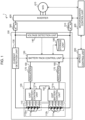
- Fig. 1 is a block diagram showing an example of a configuration of an electric system 1 of an automobile according to the first embodiment.
- the electric system 1 in the present embodiment includes a battery system 100, an inverter 400 connected to the battery system 100 via relays 300 and 310, and a motor 410 driven by the inverter 400.
- a vehicle control unit 200 determines the distribution of the driving force and the like, based on information about the battery system 100 including an SOC, information from the inverter 400 and the motor 410, information about an engine (not shown), and the like.
- the battery system 100 includes a battery pack 110, a unit battery management unit 120, a current detection unit 130, a voltage detection unit 140 that detects a total voltage of the battery pack 110, a battery pack control unit 150, and a storage unit 180.
- the battery pack 110 includes a plurality of unit batteries 111.
- the unit battery 111 is also referred to as a cell.
- the unit battery management unit 120 monitors the state of the unit battery 111.
- the current detection unit 130 detects a current flowing through the battery system 100.
- the battery pack control unit 150 controls the battery pack 110.
- the storage unit 180 stores information regarding battery characteristics of the battery pack 110, the unit battery 111, and the unit battery group 112.
- a battery voltage and a temperature of the unit battery 111, a value of a current flowing through the battery, a total voltage value of the battery pack 110, a result of diagnosing whether the unit battery 111 is overcharged or overdischarged, an abnormality signal output in a case where a communication error occurs in the unit battery management unit 120 or the like, etc. are input to the battery pack control unit 150.
- the battery voltage and the temperature of the unit battery 111 are output from the unit battery management unit 120.
- the value of the current flowing through the battery is output from the current detection unit 130.
- the total voltage value of the battery pack 110 is output from the voltage detection unit 140.
- the result of diagnosing whether the unit battery 111 is overcharged or overdischarged and the abnormality signal output in a case where the communication error occurs in the unit battery management unit 120 are output from the unit battery management unit 120.
- the battery pack control unit 150 detects the state of the battery pack 110 and the like based on the input information. The result of the process performed by the battery pack control unit 150 is transmitted to the unit battery management unit 120 and the vehicle control unit 200.
- the battery pack 110 is configured by electrically connecting a plurality of unit batteries 111 capable of storing and releasing electric energy (charging and discharging DC power) in series.
- One unit battery 111 has an output voltage of 3.0 to 4.2 V (average output voltage: 3.6 V). It is assumed that an open circuit voltage (OCV) and a state of charge (SOC) of the unit battery 111 have a correlation shown in Fig. 4 .
- OCV open circuit voltage
- SOC state of charge
- the present invention is not limited thereto, and the unit battery 111 may have other voltage specifications.
- the unit batteries 111 constituting the battery pack 110 are grouped into a predetermined number of units in order to manage and control the states of the unit batteries 111.
- the grouped unit batteries 111 are electrically connected to one another in series to constitute a unit battery group 112.
- the predetermined number of units may be for equal division, such as 1, 4, 6,..., or may be for compound division, such as a combination of 4 and 6.
- the unit battery management unit 120 monitors the states of the unit batteries 111 constituting the battery pack 110.
- the unit battery management unit 120 includes a plurality of unit battery control units 121, and one unit battery control unit 121 is assigned to the unit battery group 112 grouped as described above.
- the unit battery control unit 121 operates by receiving power from the assigned unit battery group 112, and monitors the battery voltages and temperatures of the unit batteries 111 constituting the unit battery group 112.
- unit battery control units 121a and 121b are provided to correspond to unit battery groups 112a and 112b.
- the unit battery group 112 has a configuration in which four unit batteries 111 are electrically connected to one another in series, and the four unit batteries 111 are monitored by one unit battery control unit 121, but the present invention is not limited thereto.
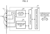
- Fig. 2 is a block diagram showing an example of a configuration of the unit battery control unit 121 according to the first embodiment.
- the unit battery control unit 121 includes a voltage detection circuit 122, a control circuit 123, a signal input/output circuit 124, and a temperature detection unit 125.
- the voltage detection circuit 122 measures a voltage between terminals of each unit battery 111.
- the temperature detection unit 125 measures a temperature of the unit battery group 112.
- the control circuit 123 transmits measurement results received from the voltage detection circuit 122 and the temperature detection unit 125 to the battery pack control unit 150 via the signal input/output circuit 124. Note that, in the description of the unit battery control unit 121, a circuit configuration for equalizing variations in voltage and SOC between the unit batteries 111 caused by self-discharge, variations in current consumption, and the like is omitted because it is well known.
- the temperature detection unit 125 has a function of measuring a temperature of the unit battery group 112.
- the temperature detection unit 125 measures one temperature as a whole of the unit battery group 112, and treats the measured temperature as a temperature representative value of the unit batteries 111 constituting the unit battery group 112.
- the temperature measured by the temperature detection unit 125 is used for various calculations for detecting the state of the unit battery 111, the unit battery group 112, or the battery pack 110. Based on this premise, it is shown in Fig. 2 as an example that one temperature detection unit 125 is provided in the unit battery control unit 121. It is also possible to measure a temperature by providing the temperature detection unit 125 for each unit battery 111 and execute various calculations based on the temperature for each unit battery 111, but the large number of temperature detection units 125 complicates the configuration of the unit battery control unit 121.
- the temperature detection unit 125 is simply shown.
- a temperature sensor is installed on an object to be measured, and the temperature sensor outputs temperature information as a voltage.
- the voltage as a measurement result output from the temperature sensor is transmitted to the signal input/output circuit 124 via the control circuit 123.
- the signal input/output circuit 124 outputs the measurement result to the outside of the unit battery control unit 121.
- a function of realizing this series of processes is implemented as the temperature detection unit 125 in the unit battery control unit 121.
- Temperature information (voltage) can also be measured using the voltage detection circuit 122.
- the battery pack control unit 150 and the unit battery management unit 120 transmit and receive signals using a signal communication unit 160 via an insulating element 170 such as photocouplers.
- the reason why the insulating element 170 is provided is that the battery pack control unit 150 and the unit battery management unit 120 use different operating power sources. That is, the unit battery management unit 120 operates by receiving power from the battery pack 110, whereas the battery pack control unit 150 uses a battery for an in-vehicle accessory (for example, a 12V battery) as a power source.
- the insulating element 170 may be mounted on a circuit board constituting the unit battery management unit 120, or may be mounted on a circuit board constituting the battery pack control unit 150. Depending on the system configuration, the insulating element 170 may be omitted.
- the unit battery control units 121a and 121b are connected in series in descending order of potential of the unit battery groups 112a and 112b monitored thereby.
- the signal output from the battery pack control unit 150 is input to the unit battery control unit 121a by the signal communication unit 160 via the insulating element 170.
- an output of the unit battery control unit 121a and an input of the unit battery control unit 121b are connected by the signal communication unit 160 to transmit a signal.
- An output of the unit battery control unit 121b is input to the battery pack control unit 150 by the signal communication unit 160 via the insulating element 170.
- This loop connection is also referred to as a daisy chain connection, a string connection, or a one-by-one connection.
- no insulating element 170 is interposed between the unit battery control unit 121a and the unit battery control unit 121b, but an insulating element 170 may be interposed therebetween.
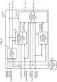
- Fig. 3 is a block diagram showing an example of a configuration of the battery pack control unit 150 according to the first embodiment.
- the battery pack control unit 150 includes an SOC/SOH calculation unit 151, an inputtable/outputtable power calculation unit 152, a voltage variation detection unit 153, and a power restriction value calculation unit 154.
- the SOC/SOH calculation unit 151 calculates and outputs an SOC and an SOH.
- the SOH deterioration rate
- SOHR resistance
- SOHC capacity
- the inputtable/outputtable power calculation unit 152 calculates and outputs maximum power (inputtable/outputtable power (inputtable power Wmax_c and outputtable power Wmax_d)) that can be input to and output from the battery.
- the voltage variation detection unit 153 calculates voltage variation information for each cell, for example, a difference between the highest cell voltage and the average voltage and a difference between the lowest cell voltage and the average voltage, and outputs a voltage variation based thereon.
- the power restriction value calculation unit 154 outputs power restriction values (inputtable power Pmax_c and outputtable power Pmax_d).
- the storage unit 180 stores information such as internal resistance characteristics, capacities when fully charged, polarization resistance characteristics, deterioration characteristics, individual difference information, and correspondence relationships between SOC and OCV of the battery pack 110, the unit battery 111, and the unit battery group 112.
- the storage unit 180 is installed outside the battery pack control unit 150 or the unit battery management unit 120, but the battery pack control unit 150 or the unit battery management unit 120 may include a storage unit.
- Fig. 4 is a diagram showing an example of a configuration of an SOC table 181 showing a relationship between SOC and OCV.
- the SOC table 181 is a data table in which a correspondence relationship between OCV and SOC in the unit battery 111 is described for each temperature.
- Fig. 4 shows correspondence relationships between OCV and SOC at some temperatures, and does not illustrate correspondence relationships between OCV and SOC at other temperatures.
- the numerical values shown in Fig. 4 are examples, and the smaller the SOC, the smaller the OCV of the battery.
- the storage unit 180 also stores a data table in which correspondence relationships between information on various battery characteristics such as internal resistance characteristics and polarization resistance characteristics and various parameters such as SOC and a temperature are described.
- the correspondence relationship between SOC and OCV is shown in the SOC table 181, but the present invention is not limited to the data table, and the correspondence relationship may be expressed by a formula or the like.
- the inputtable/outputtable power calculation unit 152 calculates maximum currents (inputtable/outputtable currents (an inputtable current Imax_c and an outputtable current Imax_d)) that can be input to and output from the battery, and multiplies the maximum currents by respective battery voltages when the inputtable current is applied, thereby outputting inputtable power Wmax_c and outputtable power Wmax_d.
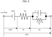
- FIG. 5 is a diagram showing an example of an equivalent circuit model in which the behavior of the voltage of the unit battery 111 is modeled.
- the equivalent circuit of Fig. 5 has a configuration in which an electromotive force component indicating an OCV of the unit battery 111, a time-independent DC resistance component Ro, and a parallel circuit of a time-dependent polarization resistance component Rp and a capacitor C are connected in series.
- the parameters (OCV, Ro, Rp and C) of the equivalent circuit shown in Fig. 5 are extracted from a test result using an actual battery.
- these parameters are extracted from a brand-new battery.
- each of a DC resistance component Ro_new, which is a time-independent internal resistance component, a polarization resistance component Rp_new, which is a time-dependent internal resistance component, and a polarization time constant ⁇ (the product of Rp and C) when the battery is brand-new is stored in the storage unit 180 as a map corresponding to the SOC or the temperature.
- a DC resistance component Ro is calculated by reflecting an SOH estimated by the SOC/SOH calculation unit 151 in the DC resistance component Ro_new stored in the storage unit 180.
- a polarization resistance component Rp is calculated by reflecting an SOH estimated by the SOC/SOH calculation unit 151 in the polarization resistance component Rp_new stored in the storage unit 180.
- Ro Ro _ new ⁇ SOH 100 1
- Rp Rp _ new ⁇ SOH 100 2
- a voltage change Vp caused by the polarization resistance component Rp is calculated as shown in Equation (3) using the polarization resistance component Rp and the polarization time constant ⁇ , with the charge/discharge time being ts.
- the voltage change V caused by the polarization resistance component Rp is obtained as a weighted average of a voltage (I ⁇ Rp) and a voltage Vp_z of a capacitor C.
- Vp I ⁇ Rp ⁇ ts ⁇ + 1 ⁇ ts ⁇ ⁇ Vp _ z
- an inputtable current Imax_c and an outputtable current Imax_d are calculated as shown in Equations (4) and (5).
- tcont represents the number of seconds (sec) of continuous current application
- Ilimit represents an upper limit current value determined in consideration of a resistance of a relay, a fuse, or the like, which is a component of the battery system 100
- Vmax represents an upper limit voltage
- Vmin represents a lower limit voltage.
- the inputtable/outputtable power calculation unit 152 calculates an inputtable maximum power (inputtable power Wmax_c) and an outputtable maximum power (outputtable power Wmax_d) according to Equations (6) and (7).
- N represents the number of cells constituting the battery system 100.
- W max _ c N ⁇ I max _ c ⁇ OCV + I max _ c ⁇ R 0 + Rp ⁇ 1 ⁇ exp ⁇ tcont ⁇ + Vp ⁇ exp ⁇ tcont ⁇ 6
- P max _ d N ⁇ I max _ d ⁇ OCV ⁇ I max _ d ⁇ R 0 + Rp ⁇ 1 ⁇ exp ⁇ tcont ⁇ + Vp ⁇ exp ⁇ tcont ⁇ 7
- Fig. 6 is a diagram showing examples of SOC and voltage waveforms in a case where a battery having a reduced capacity is present in a multi-series battery.
- Fig. 6 as shown on the left side of the diagram, it is assumed that there is one cell #1 whose capacity has deteriorated in the multi-series battery in which a plurality of unit batteries 111 are connected in series.
- the SOC waveform and the voltage waveform when the current shown in the upper part of Fig. 6 is applied to the multi-series battery are shown in the middle part of Fig. 6 and the lower part of Fig. 6 , respectively.
- the SOC of cell #1 decreases below the average SOC of all the cells constituting the multi-series battery, and the voltage of cell #1 also decreases below the average voltage. This is because cell #1 has an increased internal resistance as well as an increased capacity due to deterioration, resulting in a large change in voltage when a current is applied thereto. In addition, this is because the OCV of cell #1, whose SOC is lower than those of the other cells, is reduced, given that a battery generally has an OCV that decreases as the SOC decreases as shown in Fig. 4 .
- the larger one of an absolute value of a difference between the average voltage and the highest voltage of all the cells constituting the multi-series battery and an absolute value of a difference between the average voltage and the lowest voltage of all the cells is output as the voltage variation of the battery.
- the voltage variation is larger than or equal to a predetermined value, it is detected that there is a cell having a small capacity among all the cells constituting the multi-series battery.
- the absolute value of the difference between the average voltage and the highest voltage of all the cells constituting the multi-series battery or the absolute value of the difference between the average voltage and the lowest voltage of all the cells may be used in a fixed manner.
- voltage variation Max (
- the inputtable power Wmax_c and the outputtable power Wmax_d output from the inputtable/outputtable power calculation unit 152, the highest temperature and the lowest temperature of the unit batteries 111 constituting the battery system 100, the voltage of each unit battery 111, the voltage variation detected by the voltage variation detection unit 153, and the SOC are input to the power restriction value calculation unit 154.
- the power restriction value calculation unit 154 multiplies the inputtable power Wmax_c by an input restriction coefficient kchg (kchg ⁇ 1) and multiplies the outputtable power Wmax_d by an output restriction coefficient kdis (kdis ⁇ 1) to restrict inputtable/outputtable power.
- the power restriction value calculation unit 154 multiplies the inputtable power Wmax_c by an input restriction coefficient kchg (kchg ⁇ 1) and multiplies the outputtable power Wmax_d by an output restriction coefficient kdis (kdis ⁇ 1) to restrict inputtable/outputtable power.
- Fig. 7 is a diagram for explaining an example of a method of calculating an input restriction coefficient kchg by the power restriction value calculation unit 154.
- Fig. 7 shows an example of an input restriction coefficient according to each input value for the inputtable power Wmax_c when charged.
- Fig. 7(a) shows an input restriction coefficient (first input restriction coefficient) according to the average SOC, and the input restriction coefficient is 1 when the average SOC is lower than or equal to threshold Th11, decreases from 1 at threshold Th11, and is 0 when the average SOC is higher than or equal to threshold Th12.
- Fig. 7(b) shows an input restriction coefficient (second input restriction coefficient) according to the highest cell voltage of the cells of the multi-series battery, and the input restriction coefficient is 1 when the highest cell voltage is lower than or equal to threshold Th21, decreases from 1 at threshold Th21, and is 0 when the highest cell voltage is higher than or equal to threshold Th22.
- Fig. 7(c) shows an input restriction coefficient (third input restriction coefficient) according to the lowest cell temperature of the cells of the multi-series battery, and the input restriction coefficient is 0 when the lowest cell temperature is lower than or equal to threshold Th31, increases from 0 at threshold Th31, and is 1 when the lowest cell temperature is higher than or equal to threshold Th32.
- Fig. 7(d) shows an input restriction coefficient (fourth input restriction coefficient) according to the highest cell temperature of the cells of the multi-series battery, and the input restriction coefficient is 1 when the highest cell temperature is lower than or equal to threshold Th41, decreases from 1 at threshold Th41, and is 0 when the highest cell temperature is higher than or equal to threshold Th42.
- Fig. 8 is a diagram for explaining an example of a method of calculating an output restriction coefficient kdis by the power restriction value calculation unit 154.
- Fig. 8 shows an example of an output restriction coefficient according to each input value for the outputtable power Wmax_d when discharged.
- Fig. 8(a) shows an output restriction coefficient (first output restriction coefficient) according to the average SOC, and the output restriction coefficient is 1 when the average SOC is higher than or equal to threshold Th51, decreases from 1 at threshold Th51, and is 0 when the average SOC is lower than or equal to threshold Th52.
- Fig. 8(b) shows an output restriction coefficient (second output restriction coefficient) according to the lowest cell voltage of the cells of the multi-series battery, and the output restriction coefficient is 1 when the lowest cell voltage is higher than or equal to threshold Th61, decreases from 1 at threshold Th61, and is 0 when the lowest cell voltage is lower than or equal to threshold Th62.
- Fig. 8(c) shows an output restriction coefficient (third output restriction coefficient) according to the lowest cell temperature of the cells of the multi-series battery, and the output restriction coefficient is 1 when the lowest cell temperature is higher than or equal to threshold Th71, decreases from 1 at threshold Th71, and is 0 when the lowest cell temperature is lower than or equal to threshold Th72.
- Fig. 8(d) shows an output restriction coefficient (fourth output restriction coefficient) according to the highest cell temperature of the cells of the multi-series battery, and the output restriction coefficient is 0 when the highest cell temperature is higher than or equal to threshold Th81, decreases from 1 at threshold Th81, and is 0 when the highest cell temperature is lower than or equal to threshold Th82.
- Fig. 9 is a diagram for explaining a problem of power restriction control based on the average SOC.
- Fig. 9 shows a voltage waveform (the middle part of Fig. 9 ) and an SOC waveform (the lower part of Fig. 9 ) when a current (the upper part of Fig. 9 ) is input so that an average SOC of the multi-series battery as shown in the lower part of Fig. 9 varies within an SOC usage range, for example, with a lower limit of 30% and an upper limit of 80%, in a case where there is a unit battery 111 (cell #1) having a small capacity among the plurality of batteries constituting the multi-series battery.
- the voltage of cell #1 varies more widely up and down than the average voltage of the multi-series battery. Therefore, it can be seen that the SOC of cell #1 deviates from the SOC usage range when the average SOC varies within the SOC usage range with the lower limit of 30% and the upper limit of 80%.
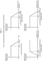
- Fig. 10 is a diagram for explaining an example of the SOC restriction start timing according to a voltage variation in the first embodiment.
- the horizontal axis represents an SOC
- the vertical axis represents a restriction coefficient.
- Fig. 10(a) shows a charging side, that is, an input restriction coefficient according to an SOC, which corresponds to Fig. 7(a) .
- Fig. 10(b) shows a discharging side, that is, an output restriction coefficient according to an SOC, which corresponds to Fig. 8(a) .
- the restriction start point (the point at which the restriction coefficient starts to decrease) and the restriction end point (the point at which the restriction coefficient decreases to 0) are generally shifted to the left side of the diagram, that is, in a direction in which the SOC decreases. This means that, during charging, the start of the restriction according to the SOC is advanced as the voltage variation between the batteries of the multi-series battery increases.
- the input restriction coefficient (first input restriction coefficient) according to the SOC is 1 when the SOC is lower than or equal to SOC_chg_start1, decreases from 1 at SOC_chg_start1, and is 0 when the SOC is higher than or equal to SOC_chg_end1.
- the input restriction coefficient according to the SOC is 1 when the SOC is lower than or equal to SOC_chg_start2, decreases from 1 at SOC_chg_start2, and is 0 when the SOC is higher than or equal to SOC_chg_end2.
- the input restriction coefficient according to the SOC is 1 when the SOC is lower than or equal to SOC_chg_start3, decreases from 1 at SOC_chg_start3, and is 0 when the SOC is higher than or equal to SOC_chg_end3.
- the restriction start point (the point at which the restriction coefficient starts to decrease) and the restriction end point (the point at which the restriction coefficient decreases to 1) are generally shifted to the right side of the diagram, that is, in a direction in which the SOC increases. This means that, during discharging, the start of the restriction according to the SOC is advanced as the voltage variation of the cell of the multi-series battery increases.
- the output restriction coefficient (first output restriction coefficient) according to the SOC is 1 when the SOC is higher than or equal to SOC_dis_start1, decreases from 1 at SOC_dis_start1, and is 0 when the SOC is lower than or equal to SOC_dis_end1.
- the output restriction coefficient according to the SOC is 1 when the SOC is higher than or equal to SOQ_dis_start2, decreases from 1 at SOQ_dis_start2, and is 0 when the SOC is lower than or equal to SOC_dis_end2.
- the output restriction coefficient according to the SOC is 1 when the SOC is higher than or equal to SOC_dis_start3, decreases from 1 at SOC_dis_start3, and is 0 when the SOC is lower than or equal to SOC_dis_end3.
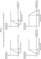
- Fig. 11 shows a restriction start point (SOC_chg_start or SOC_dis_start) and a restriction end point (SOC_chg_end or SOC_dis_end) according to the voltage variation on each of the charging side ( Fig. 11(a) ) and the discharging side ( Fig. 11 (b) ).
- the horizontal axis represents a voltage variation
- the vertical axis represents an SOC.
- SOC_chg_start and SOC_chg_end are set to lower values.
- SOC_dis_start and SOC_dis_end are set to higher values.
- the relationship shown in Fig. 11 is stored in the storage unit 180 as an SOC restriction map for each voltage variation.
- the power restriction value calculation unit 154 acquires input restriction conditions (SOC_chg_start and SOC_chg_end) and output restriction conditions (SOC_dis_start and SOC_dis_end) according to the SOC, and uses the input restriction conditions and the output restriction conditions for calculating input/output restriction coefficients according to the SOC.
- Fig. 12 is a diagram showing examples of power, voltage, SOC, input/output restriction coefficient, and input/output restriction condition waveforms before the first embodiment is applied.
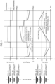
- Fig. 13 is a diagram showing examples of power, voltage, SOC, input/output restriction coefficient, and input/output restriction condition waveforms after the first embodiment is applied.
- Figs. 12 and 13 show time-series changes of values when a certain load pattern is input to a multi-series battery including a battery (cell #1) having a smaller capacity due to deterioration than the other batteries among the plurality of batteries constituting the multi-series battery.
- the values indicating time-series changes in Figs. 12 and 13 are a power, a voltage, an SOC, an input restriction coefficient kchg, an output restriction coefficient kdis, input restriction conditions (SOC_chg_start and SOC_chg_end), and output restriction conditions (SOC_dis_start and SOC_dis_end) of the battery.
- the certain load pattern is a pattern in which discharging power is input to the multi-series battery for a predetermined time from time t11 to time t13, a pause period from time t13 to time t14 is set, and then charging power is input to the multi-series battery for a predetermined time from time t14 to time t16.
- the power waveform input to the multi-series battery is restricted to be within the range between the inputtable power Pmax_c and the outputtable power Pmax_d.
- the outputtable power can be restricted such that the average SOC is not below 30%, which is the lower limit, but the SOC of cell #1 greatly changes as its capacity is smaller than those of the other cells, and cell #1 is discharged below 30% as the lower limit.
- the input restriction conditions (SOC_chg_start and SOC_chg_end) and the output restriction conditions (SOC _dis_start and SOC_dis_end) change as shown in Figs. 13(e) and 13(f) based on the relationship between the voltage variation and the input/output restriction conditions according to the SOC shown in Fig. 11 .
- the input restriction coefficient kchg is determined based on the input restriction conditions (SOC_chg_start and SOC_chg_end), and the output restriction coefficient kdis is determined based on the output restriction conditions (SOC_dis_start and SOC_dis_end).
- the restriction coefficient is set to be smaller than "1" at an earlier timing in the present embodiment than before the present embodiment is applied. That is, the input restriction coefficient kchg is set to be smaller than "1" from the time when the average SOC is lower during charging, and the output restriction coefficient kdis is set to be smaller than "1" from the time when the average SOC is higher during discharging. Accordingly, the inputtable power Pmax_c and the outputtable power Pmax_d also decrease.
- the outputtable power Pmax_d can be controlled so that an SOC of a battery (cell #1) having a small capacity is not below the lower limit, by decreasing the output restriction coefficient kdis calculated based on the average SOC from "1" at time t22 when the SOC is higher than 30% as the lower limit to "0" at time t13.
- the inputtable power Pmax_c can be controlled such that an SOC of a battery (cell #1) having a small capacity is not beyond the upper limit, by decreasing the input restriction coefficient kchg calculated based on the average SOC from "1" at time t25 when the SOC is lower than 80% as the upper limit to "0" at time t16.
- the input restriction coefficient kchg and the output restriction coefficient kdis based on the average SOC are determined according to the larger one of the absolute values of the differences between the average voltage and the highest and lowest voltages of the cell voltages.
- a battery control device that controls a battery pack in which a plurality of batteries are connected to each other detects a voltage variation between the plurality of batteries, and restricts inputtable/outputtable power of the battery pack based on a restriction coefficient calculated based on a charging rate (average SOC) of the battery pack and the voltage variation. Therefore, a battery having the lowest capacity among the plurality of batteries can be detected based on the voltage variation, and the restriction coefficient according to the average SOC defining a restriction start point and a restriction end point different depending on the voltage variation can be calculated with a light load. In addition, while the battery pack is charged and discharged, the battery having the smallest capacity in the battery pack can be controlled not to deviate from the SOC usage range.
- the voltage variation is an index based on a difference between an average voltage and a highest voltage of the plurality of batteries or a difference between the average voltage and a lowest voltage of the plurality of batteries. Therefore, it can be estimated by a simple calculation that there is a battery whose internal resistance increases as its capacity decreases due to deterioration and which deviates from the SOC usage range when charged and discharged among the plurality of batteries.
- the inputtable/outputtable power is restricted by calculating a restriction coefficient of input/output power based on the voltage variation and the average SOC and multiplying the inputtable/outputtable power by the restriction coefficient, the inputtable/outputtable power can be restricted by the calculation with the light load.
- the restriction coefficient of the inputtable power according to the average SOC is 1 when the average SOC is lower than or equal to a first threshold, starts to decrease from 1 when the average SOC is the first threshold, becomes 0 when the average SOC is a second threshold larger than a third threshold, and is 0 when the average SOC is higher than or equal to the second threshold, and the first threshold and the second threshold are smaller as the voltage variation is larger. Therefore, the greater the voltage variation, the earlier the restriction of the inputtable power can be implemented in such a manner that the inputtable power decreases from a certain point of time along with the increase in average SOC, and then is set to 0 after a certain point of time.
- a smallest value among an input restriction coefficient according to an average SOC, an input restriction coefficient according to a highest voltage of the batteries, an input restriction coefficient according to a lowest temperature of the batteries, and an input restriction coefficient according to a highest temperature of the batteries is set as a final input restriction coefficient. Therefore, the inputtable/outputtable power can be restricted to maximize the safety of the battery in terms of four indexes: the average SOC, the highest voltage, the lowest temperature, and the highest temperature.
- the restriction coefficient of the outputtable power according to the average SOC is 1 when the average SOC is higher than or equal to a third threshold, starts to decrease from 1 when the average SOC is the third threshold, becomes 0 when the average SOC is a fourth threshold smaller than the third threshold, and is 0 when the average SOC is lower than or equal to the fourth threshold, and the third threshold and the fourth threshold are larger as the voltage variation is larger. Therefore, the greater the voltage variation, the earlier the control of the outputtable power can be implemented in such a manner that the outputtable power decreases from a certain point of time along with the decrease in average SOC, and then is set to 0 after a certain point of time.
- a smallest value among an output restriction coefficient according to an average SOC, an output restriction coefficient according to a lowest voltage of the batteries, an output restriction coefficient according to a lowest temperature of the batteries, and an output restriction coefficient according to a highest temperature of the batteries is set as a final output restriction coefficient. Therefore, the outputtable power can be restricted to maximize the safety of the battery in terms of four indexes: the average SOC, the highest voltage, the lowest temperature, and the highest temperature.
- the condition for detecting the voltage variation is not defined.
- An object of the present invention is to detect a variation in SOC between batteries constituting a multi-series battery and prevent an SOC of each battery from deviating from an SOC usage range. Therefore, it is preferable to determine a restriction coefficient of inputtable/outputtable power by detecting a voltage variation under a condition suitable for detecting an SOC variation.
- the voltage while a current is applied includes a voltage change due to an internal resistance
- the voltage variation including the voltage change does not necessarily match the SOC variation. Therefore, in the present embodiment, a condition for detecting a voltage variation will be described to more accurately treating the voltage variation between the batteries constituting the multi-series battery as an SOC variation.
- the battery system 100 includes a battery pack control unit 150B instead of the battery pack control unit 150.
- the battery pack control unit 150B includes a voltage variation detection unit 153B instead of the voltage variation detection unit 153.
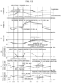
- Fig. 14 is a block diagram showing an example of a configuration of the battery pack control unit 150B according to the second embodiment.
- a value of a current flowing through the battery pack 110 is added to the voltage variation detection unit 153B, as compared with the voltage variation detection unit 153 according to the first embodiment.
- the object of the present invention is to prevent the SOC of each battery constituting the multi-series battery from deviating from the SOC usage range, it is preferable to detect a voltage variation between the batteries under the condition that an SOC variation between the batteries can be detected with high accuracy. Therefore, in the present embodiment, the voltage variation detection unit 153B detects a voltage variation under the condition that the current value added as an input is smaller than or equal to a predetermined value, and determines an input restriction coefficient kchg and an output restriction coefficient kdis.
- a voltage variation is detected based on Equation (8) at a voltage variation detection timing satisfying the voltage variation detection condition that the current value is a small value smaller than or equal to the predetermined value. Then, as shown in Figs. 10 and 11 , the input/output restriction conditions according to the SOC are determined.
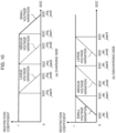
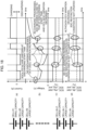
- Fig. 16 is a diagram showing examples of current, voltage, SOC, and input/output restriction coefficient waveforms after the second embodiment is applied. Similarly to the diagram ( Fig. 13 ) for explaining the effects of the first embodiment, Fig. 16 shows waveforms when a load pattern in which discharging and charging are repeated is input to a multi-series battery including one small-capacity battery (cell #1).
- an input restriction coefficient kchg and an output restriction coefficient kdis are determined according to a voltage variation detected during a pause period between discharging in a no-load state in which no current flows and charging as a voltage variation detection timing as shown in Fig. 16(a) . Then, similarly to the first embodiment, the inputtable power Pmax_c and the outputtable power Pmax_d are restricted to decrease. As a result, as shown in Fig. 16(c) , charging and discharging can be performed so that the SOCs of all the batteries, including cell #1 having a small capacity, do not deviate from the SOC usage range.
- the present embodiment it is possible to more accurately evaluate the voltage variation and the SOC variation by detecting the voltage variation when the condition that the current value is smaller than or equal to the predetermined value is satisfied. Then, an input/output restriction coefficient according to the SOC is determined based on the accurate voltage variation. Therefore, it is possible to more accurately calculate inputtable power Pmax_c and outputtable power Pmax_d with which an SOC of a battery having the smallest capacity does not deviate from the SOC usage range.
- a voltage variation which is a difference between the average voltage and the highest/lowest voltage of the plurality of batteries constituting the multi-series battery, is detected only when the condition that a value of a current flowing through the battery is smaller than or equal to the predetermined value is satisfied. Based on the detected voltage variation, a restriction coefficient of inputtable/outputtable power according to the average SOC is determined.
- Fig. 17 is a diagram for explaining a problem in detecting a voltage variation.
- Fig. 17(a) shows a current waveform input to the multi-series battery
- Fig. 17(b) shows a voltage when the current of Fig. 17(a) is input
- Fig. 17(c) shows an SOC waveform when the current of Fig. 17(a) is input.
- the battery system 100 includes a battery pack control unit 150C instead of the battery pack control unit 150, and the battery pack control unit 150C includes a power restriction value calculation unit 154C instead of the power restriction value calculation unit 154 ( Fig. 3 ).
- the battery pack control unit 150C includes a power restriction value calculation unit 154C instead of the power restriction value calculation unit 154 ( Fig. 3 ).
- the processing content of the power restriction value calculation unit 154C is different from that of the power restriction value calculation unit 154, and the other configurations are the same.
- the power restriction value calculation unit 154C adopts a currently detected voltage variation only when the currently detected voltage variation is larger than previously detected voltage variations.
- the currently detected voltage variation is smaller than the previously detected voltage variations, the largest voltage variation is adopted among the previously detected voltage variations.
- the previously detected voltage variations are stored in a storage area such as the storage unit 180. As a result, a voltage difference detected under the condition that it is difficult to identify a battery having a small capacity during charging and discharging as described above is not adopted in calculating a voltage variation, thereby making it possible to prevent an erroneous detection that no SOC variation occurs.
- Fig. 18 is a diagram for explaining an example of a method of determining an input/output restriction condition according to a voltage variation and an SOC in the third embodiment.
- Fig. 18(a) shows a current waveform input to the multi-series battery
- Fig. 18(b) shows a voltage when a current is input
- Fig. 18(c) shows an input restriction condition according to an SOC when the current is input
- Fig. 18(d) shows an output restriction condition according to an SOC.
- a current is input to the battery system 100, from before discharging is started at time 0 when voltages and SOCs are uniform, going through discharging, pausing, discharging, pausing, charging, pausing, and charging.
- the input/output restriction condition according to the SOC is determined from a voltage variation detected during a pause period immediately after first-cycle discharging.
- the voltage variation is larger than that at time 0. Therefore, as shown in Fig. 18(c) , the input restriction conditions (SOC_chg_start and SOC_chg_end) have smaller values, and as shown in Fig. 18 (d) , the output restriction conditions (SOC_dis_start and SOC_dis_end) have larger values. Since the SOC variation and the voltage variation further increase even after second-cycle discharging, the input/output restriction condition according to the voltage variation become stricter.
- an input/output restriction condition determined according to the largest voltage variation among voltage variations detected in time series is continuously maintained. As a result, it is possible to charge and discharge a battery having a small capacity without deviating from the SOC usage range, while preventing an erroneous detection that there is no voltage variation even though there is a voltage variation.
- the present invention is not limited to the configuration of the above-described embodiments, and includes various modifications.
- the above-described embodiments have been described in detail in order to describe the present invention in an easy-to-understand manner, and are not necessarily limited to those having all the described configurations.
- a part of a configuration of a certain embodiment can be replaced with a configuration of another embodiment, and a configuration of a certain embodiment can be added to a configuration of another embodiment.
Landscapes
- Engineering & Computer Science (AREA)
- Power Engineering (AREA)
- Life Sciences & Earth Sciences (AREA)
- Sustainable Development (AREA)
- Sustainable Energy (AREA)
- Transportation (AREA)
- Mechanical Engineering (AREA)
- Manufacturing & Machinery (AREA)
- Chemical & Material Sciences (AREA)
- Chemical Kinetics & Catalysis (AREA)
- Electrochemistry (AREA)
- General Chemical & Material Sciences (AREA)
- Microelectronics & Electronic Packaging (AREA)
- Secondary Cells (AREA)
- Charge And Discharge Circuits For Batteries Or The Like (AREA)
- Electric Propulsion And Braking For Vehicles (AREA)
Abstract
Description
- The present invention relates to a battery control device and a battery system.
- An electric vehicle system mounted on a vehicle such as an electric vehicle (EV), a plug-in hybrid electric vehicle (PHEV), or a hybrid electric vehicle (HEV) includes a battery that supplies power to a drive source and a battery control device. In order to maximize the performance of the battery, the battery control device detects a voltage, a temperature, and a current of the battery, and based thereon, calculates a state of charge (SOC, charging rate) of the battery, a state of health (SOH, deterioration rate) of the battery, and power that can be input/output when the battery is charged/discharged (inputtable/outputtable power).
- Using an upper limit voltage or a lower limit voltage of the battery and an internal resistance of the battery, the inputtable/outputtable power of the battery is calculated as maximum power that can be input and output within a range in which the battery voltage does not deviate from the upper and lower limit voltages. In a multi-series battery system in which a plurality of batteries are connected to one another in series, inputtable/outputtable power is restricted to be around a preset restriction value so that a temperature, an SOC, and a voltage of the battery are within the respective usage ranges when the battery is charged/discharged.
- However, if inputtable/outputtable power is restricted using only an average SOC of all the batteries as an index for determining the implementation of the restriction of the inputtable/outputtable power, while all the batteries of the multi-series battery system are regarded as one battery, there are the following disadvantages. That is, in the multi-series battery system, if deterioration progresses in only a specific battery, and its internal resistance increases, resulting in a decrease in capacity, there is a possibility that the specific battery will deviate from its SOC usage range when charged or discharged.
- Therefore,
Patent Literature 1 discloses a conventional art in which a variation in internal resistance extracted based on a variation in voltage change between batteries when a current flows through the batteries is reflected in calculation of inputtable/outputtable power. According to this conventional art, it is possible to avoid a deviation of a battery from the upper and lower limit voltages that may be caused by a variation in internal resistance between the batteries. - Patent Literature 1:
JP 3528428 B2 - However, during charging and discharging, where the voltage change caused by the internal resistance greatly changes the SOC at a relatively small current, a small-capacity battery may deviate from its SOC usage range. Therefore, it may be considered to individually estimate an SOC of each battery constituting the multi-series battery system and reflect the SOC of each battery in calculation of inputtable/outputtable power.
- However, it is required to provide a temperature sensor for measuring a temperature, which is necessary for estimating an SOC, for each battery, leading to an increase in cost of the battery system and an increase in calculation load.
- The present invention has been made in view of the above, and an object of the present invention is to secure the reliability of the battery system by avoiding deviations from the SOC usage range of all the batteries of the battery system while avoiding an increase in cost and an increase in calculation load of the battery system and securing the input/output performance of the batteries.
- In order to solve the above-described problems of the conventional art, a battery control device according to the present invention is a battery control device that controls a battery pack in which a plurality of batteries are connected to each other, the battery control device detecting a voltage variation between the plurality of batteries; calculating a restriction coefficient based on a charging rate of the battery pack and the voltage variation; and restricting inputtable/outputtable power based on the restriction coefficient, the inputtable/outputtable power being maximum power inputtable to and outputtable from the battery pack.
- According to the present invention, it is possible to secure the reliability of the battery system by avoiding deviations from the SOC usage range of all the batteries of the battery system while avoiding an increase in cost and an increase in calculation load of the battery system and securing the input/output performance of the batteries.
-
-
Fig. 1 is a block diagram showing an example of a configuration of an electric system of an automobile according to a first embodiment. -
Fig. 2 is a block diagram showing an example of a configuration of a unit battery control unit according to the first embodiment. -
Fig. 3 is a block diagram showing an example of a configuration of a battery pack control unit according to the first embodiment. -
Fig. 4 is a diagram showing an example of a configuration of an SOC table showing a relationship between SOC and OCV. -
Fig. 5 is a diagram showing an example of a voltage equivalent circuit model in which a behavior of a voltage of a unit battery is modeled. -
Fig. 6 is a diagram showing examples of SOC and voltage waveforms in a case where a battery having a reduced capacity is present in a multi-series battery. -
Fig. 7 is a diagram for explaining an example of a method of calculating an input restriction coefficient by a power restriction value calculation unit. -
Fig. 8 is a diagram for explaining an example of a method of calculating an output restriction coefficient by the power restriction value calculation unit. -
Fig. 9 is a diagram for explaining a problem of power restriction control based on an average SOC. -
Fig. 10 is a diagram for explaining an example of an SOC restriction start timing according to a voltage variation in the first embodiment. -
Fig. 11 is a diagram for explaining examples of a restriction start point and a restriction end point according to a voltage variation in the first embodiment. -
Fig. 12 is a diagram showing examples of power, voltage, SOC, input/output restriction coefficient, and input/output restriction condition waveforms before the first embodiment is applied. -
Fig. 13 is a diagram showing examples of power, voltage, SOC, input/output restriction coefficient, and input/output restriction condition waveforms after the first embodiment is applied. -
Fig. 14 is a block diagram showing an example of a configuration of a battery pack control unit according to a second embodiment. -
Fig. 15 is a diagram showing an example of a voltage variation detection timing according to the second embodiment. -
Fig. 16 is a diagram showing examples of current, voltage, SOC, and input/output restriction coefficient waveforms after the second embodiment is applied. -
Fig. 17 is a diagram for explaining a problem in detecting a voltage variation. -
Fig. 18 is a diagram for explaining an example of a method of determining an input/output restriction condition according to a voltage variation and an SOC in a third embodiment. - Hereinafter, embodiments of the present invention will be described with reference to the drawings. In the following embodiments, a case where the present invention is applied to a battery system constituting a power source of a hybrid vehicle will be described. However, the configurations of the embodiments to be described below are not limited thereto, and can also be applied to a storage battery control circuit or the like of an energy storage apparatus constituting a power source of a passenger vehicle such as a plug-in hybrid vehicle or an electric vehicle, an industrial vehicle such as a hybrid truck, or a railway vehicle.
- In the following embodiments, a case where a lithium ion battery is adopted will be described as an example, but a lead battery, a nickel hydrogen battery, a multivalent cation battery, an electric double layer capacitor, a hybrid capacitor, or the like can also be used as long as it is a chargeable/dischargeable secondary battery. In addition, in the following embodiments, a battery pack is configured by connecting a plurality of unit batteries in series, but the present invention can also be applied to a system configured by connecting in series a plurality of battery packs, each including a plurality of unit batteries connected in parallel, or a system configured by connecting in parallel a plurality of battery packs, each including a plurality of unit batteries connected in series.
- In the following description, when elements of the same type are described in a distinguished manner, reference numerals with subscripts added to the main body portion are used. When the same kind of elements are described without distinction, only the main body portion excluding subscripts is used as a reference numeral. In addition, in the description of the embodiments, descriptions of configurations and processes that have already been described will be omitted, or descriptions of configurations and processes that are the same as those of the previously described embodiments will be omitted, and differences will be mainly described.
- In addition, the number of various components exemplified in the following description is merely an example.
- A first embodiment of the present invention will be described with reference to
Figs. 1 to 10 . -
Fig. 1 is a block diagram showing an example of a configuration of anelectric system 1 of an automobile according to the first embodiment. Theelectric system 1 in the present embodiment includes abattery system 100, aninverter 400 connected to thebattery system 100 viarelays motor 410 driven by theinverter 400. Avehicle control unit 200 determines the distribution of the driving force and the like, based on information about thebattery system 100 including an SOC, information from theinverter 400 and themotor 410, information about an engine (not shown), and the like. - The
battery system 100 includes abattery pack 110, a unitbattery management unit 120, acurrent detection unit 130, avoltage detection unit 140 that detects a total voltage of thebattery pack 110, a batterypack control unit 150, and astorage unit 180. Thebattery pack 110 includes a plurality ofunit batteries 111. Theunit battery 111 is also referred to as a cell. - The unit
battery management unit 120 monitors the state of theunit battery 111. Thecurrent detection unit 130 detects a current flowing through thebattery system 100. The batterypack control unit 150 controls thebattery pack 110. Thestorage unit 180 stores information regarding battery characteristics of thebattery pack 110, theunit battery 111, and theunit battery group 112. - A battery voltage and a temperature of the
unit battery 111, a value of a current flowing through the battery, a total voltage value of thebattery pack 110, a result of diagnosing whether theunit battery 111 is overcharged or overdischarged, an abnormality signal output in a case where a communication error occurs in the unitbattery management unit 120 or the like, etc. are input to the batterypack control unit 150. - The battery voltage and the temperature of the
unit battery 111 are output from the unitbattery management unit 120. The value of the current flowing through the battery is output from thecurrent detection unit 130. The total voltage value of thebattery pack 110 is output from thevoltage detection unit 140. The result of diagnosing whether theunit battery 111 is overcharged or overdischarged and the abnormality signal output in a case where the communication error occurs in the unitbattery management unit 120 are output from the unitbattery management unit 120. The batterypack control unit 150 detects the state of thebattery pack 110 and the like based on the input information. The result of the process performed by the batterypack control unit 150 is transmitted to the unitbattery management unit 120 and thevehicle control unit 200. - The
battery pack 110 is configured by electrically connecting a plurality ofunit batteries 111 capable of storing and releasing electric energy (charging and discharging DC power) in series. Oneunit battery 111 has an output voltage of 3.0 to 4.2 V (average output voltage: 3.6 V). It is assumed that an open circuit voltage (OCV) and a state of charge (SOC) of theunit battery 111 have a correlation shown inFig. 4 . However, the present invention is not limited thereto, and theunit battery 111 may have other voltage specifications. - The
unit batteries 111 constituting thebattery pack 110 are grouped into a predetermined number of units in order to manage and control the states of theunit batteries 111. The groupedunit batteries 111 are electrically connected to one another in series to constitute aunit battery group 112. The predetermined number of units may be for equal division, such as 1, 4, 6,..., or may be for compound division, such as a combination of 4 and 6. - The unit
battery management unit 120 monitors the states of theunit batteries 111 constituting thebattery pack 110. The unitbattery management unit 120 includes a plurality of unitbattery control units 121, and one unitbattery control unit 121 is assigned to theunit battery group 112 grouped as described above. The unitbattery control unit 121 operates by receiving power from the assignedunit battery group 112, and monitors the battery voltages and temperatures of theunit batteries 111 constituting theunit battery group 112. - In
Fig. 1 , unitbattery control units 121a and 121b are provided to correspond tounit battery groups 112a and 112b. In the present embodiment, in order to simplify the description, it is assumed that theunit battery group 112 has a configuration in which fourunit batteries 111 are electrically connected to one another in series, and the fourunit batteries 111 are monitored by one unitbattery control unit 121, but the present invention is not limited thereto. -
Fig. 2 is a block diagram showing an example of a configuration of the unitbattery control unit 121 according to the first embodiment. The unitbattery control unit 121 includes avoltage detection circuit 122, acontrol circuit 123, a signal input/output circuit 124, and atemperature detection unit 125. - The
voltage detection circuit 122 measures a voltage between terminals of eachunit battery 111. Thetemperature detection unit 125 measures a temperature of theunit battery group 112. Thecontrol circuit 123 transmits measurement results received from thevoltage detection circuit 122 and thetemperature detection unit 125 to the batterypack control unit 150 via the signal input/output circuit 124. Note that, in the description of the unitbattery control unit 121, a circuit configuration for equalizing variations in voltage and SOC between theunit batteries 111 caused by self-discharge, variations in current consumption, and the like is omitted because it is well known. - The
temperature detection unit 125 has a function of measuring a temperature of theunit battery group 112. Thetemperature detection unit 125 measures one temperature as a whole of theunit battery group 112, and treats the measured temperature as a temperature representative value of theunit batteries 111 constituting theunit battery group 112. The temperature measured by thetemperature detection unit 125 is used for various calculations for detecting the state of theunit battery 111, theunit battery group 112, or thebattery pack 110. Based on this premise, it is shown inFig. 2 as an example that onetemperature detection unit 125 is provided in the unitbattery control unit 121. It is also possible to measure a temperature by providing thetemperature detection unit 125 for eachunit battery 111 and execute various calculations based on the temperature for eachunit battery 111, but the large number oftemperature detection units 125 complicates the configuration of the unitbattery control unit 121. - In
Fig. 2 , thetemperature detection unit 125 is simply shown. In practice, a temperature sensor is installed on an object to be measured, and the temperature sensor outputs temperature information as a voltage. The voltage as a measurement result output from the temperature sensor is transmitted to the signal input/output circuit 124 via thecontrol circuit 123. The signal input/output circuit 124 outputs the measurement result to the outside of the unitbattery control unit 121. A function of realizing this series of processes is implemented as thetemperature detection unit 125 in the unitbattery control unit 121. Temperature information (voltage) can also be measured using thevoltage detection circuit 122. - The battery
pack control unit 150 and the unitbattery management unit 120 transmit and receive signals using asignal communication unit 160 via an insulatingelement 170 such as photocouplers. The reason why the insulatingelement 170 is provided is that the batterypack control unit 150 and the unitbattery management unit 120 use different operating power sources. That is, the unitbattery management unit 120 operates by receiving power from thebattery pack 110, whereas the batterypack control unit 150 uses a battery for an in-vehicle accessory (for example, a 12V battery) as a power source. The insulatingelement 170 may be mounted on a circuit board constituting the unitbattery management unit 120, or may be mounted on a circuit board constituting the batterypack control unit 150. Depending on the system configuration, the insulatingelement 170 may be omitted. - Next, a communication unit between the battery
pack control unit 150 and the unitbattery control units 121a and 121b in the present embodiment will be described. The unitbattery control units 121a and 121b are connected in series in descending order of potential of theunit battery groups 112a and 112b monitored thereby. - The signal output from the battery
pack control unit 150 is input to the unit battery control unit 121a by thesignal communication unit 160 via the insulatingelement 170. Similarly, an output of the unit battery control unit 121a and an input of the unitbattery control unit 121b are connected by thesignal communication unit 160 to transmit a signal. An output of the unitbattery control unit 121b is input to the batterypack control unit 150 by thesignal communication unit 160 via the insulatingelement 170. - In this manner, the battery
pack control unit 150 and the unitbattery control units 121a and 121b are connected in a loop shape by thesignal communication unit 160. This loop connection is also referred to as a daisy chain connection, a string connection, or a one-by-one connection. - In the present embodiment, no insulating
element 170 is interposed between the unit battery control unit 121a and the unitbattery control unit 121b, but an insulatingelement 170 may be interposed therebetween. -
Fig. 3 is a block diagram showing an example of a configuration of the batterypack control unit 150 according to the first embodiment. In the present embodiment, the description of the process based on the diagnosis result related to theunit battery 111 or the abnormality signal output in a case where the communication error occurs in the unitbattery management unit 120 is omitted. The batterypack control unit 150 includes an SOC/SOH calculation unit 151, an inputtable/outputtablepower calculation unit 152, a voltagevariation detection unit 153, and a power restrictionvalue calculation unit 154. - With the average voltage of the
unit batteries 111 constituting thebattery pack 110, the current flowing through thebattery pack 110, and the average temperature of theunit batteries 111 detected by thetemperature detection unit 125 as inputs, the SOC/SOH calculation unit 151 calculates and outputs an SOC and an SOH. In the present embodiment, the SOH (deterioration rate) is a state of health based on resistance (SOHR), but may be a state of health based on capacity (SOHC). - With the SOC and the SOHR calculated by the SOC/
SOH calculation unit 151, the current of thebattery pack 110, and the lowest temperature in thebattery system 100 as inputs, the inputtable/outputtablepower calculation unit 152 calculates and outputs maximum power (inputtable/outputtable power (inputtable power Wmax_c and outputtable power Wmax_d)) that can be input to and output from the battery. - With the voltage of each
unit battery 111 and the average voltage of theunit batteries 111 as inputs, the voltagevariation detection unit 153 calculates voltage variation information for each cell, for example, a difference between the highest cell voltage and the average voltage and a difference between the lowest cell voltage and the average voltage, and outputs a voltage variation based thereon. - With the inputtable power Wmax_c and the outputtable power Wmax_d output from the inputtable/outputtable
power calculation unit 152, the SOC output from the SOC/SOH calculation unit 151, the lowest temperature and the highest temperature of each cell, the voltage of each cell, and the voltage variation output from the voltagevariation detection unit 153 as inputs, the power restrictionvalue calculation unit 154 outputs power restriction values (inputtable power Pmax_c and outputtable power Pmax_d). - The
storage unit 180 stores information such as internal resistance characteristics, capacities when fully charged, polarization resistance characteristics, deterioration characteristics, individual difference information, and correspondence relationships between SOC and OCV of thebattery pack 110, theunit battery 111, and theunit battery group 112. In the present embodiment, thestorage unit 180 is installed outside the batterypack control unit 150 or the unitbattery management unit 120, but the batterypack control unit 150 or the unitbattery management unit 120 may include a storage unit. -
Fig. 4 is a diagram showing an example of a configuration of an SOC table 181 showing a relationship between SOC and OCV. The SOC table 181 is a data table in which a correspondence relationship between OCV and SOC in theunit battery 111 is described for each temperature.Fig. 4 shows correspondence relationships between OCV and SOC at some temperatures, and does not illustrate correspondence relationships between OCV and SOC at other temperatures. The numerical values shown inFig. 4 are examples, and the smaller the SOC, the smaller the OCV of the battery. - Similarly to the SOC table 181, the
storage unit 180 also stores a data table in which correspondence relationships between information on various battery characteristics such as internal resistance characteristics and polarization resistance characteristics and various parameters such as SOC and a temperature are described. In the present embodiment, the correspondence relationship between SOC and OCV is shown in the SOC table 181, but the present invention is not limited to the data table, and the correspondence relationship may be expressed by a formula or the like. - Referring back to
Fig. 3 , the description will be made. With the battery parameters, the SOC, the SOHR, and the current stored in thestorage unit 180, and the lowest temperature in thebattery system 100 as inputs, the inputtable/outputtablepower calculation unit 152 calculates maximum currents (inputtable/outputtable currents (an inputtable current Imax_c and an outputtable current Imax_d)) that can be input to and output from the battery, and multiplies the maximum currents by respective battery voltages when the inputtable current is applied, thereby outputting inputtable power Wmax_c and outputtable power Wmax_d. - A method of calculating an inputtable current Imax_c and an outputtable current Imax_d by the inputtable/outputtable
power calculation unit 152 will be described with reference toFig. 5. Fig. 5 is a diagram showing an example of an equivalent circuit model in which the behavior of the voltage of theunit battery 111 is modeled. The equivalent circuit ofFig. 5 has a configuration in which an electromotive force component indicating an OCV of theunit battery 111, a time-independent DC resistance component Ro, and a parallel circuit of a time-dependent polarization resistance component Rp and a capacitor C are connected in series. - The parameters (OCV, Ro, Rp and C) of the equivalent circuit shown in
Fig. 5 are extracted from a test result using an actual battery. In the present embodiment, these parameters are extracted from a brand-new battery. Then, each of a DC resistance component Ro_new, which is a time-independent internal resistance component, a polarization resistance component Rp_new, which is a time-dependent internal resistance component, and a polarization time constant τ (the product of Rp and C) when the battery is brand-new is stored in thestorage unit 180 as a map corresponding to the SOC or the temperature. - As shown in Equation (1), a DC resistance component Ro is calculated by reflecting an SOH estimated by the SOC/
SOH calculation unit 151 in the DC resistance component Ro_new stored in thestorage unit 180. Similarly, as shown in Equation (2), a polarization resistance component Rp is calculated by reflecting an SOH estimated by the SOC/SOH calculation unit 151 in the polarization resistance component Rp_new stored in thestorage unit 180.
- In addition, a voltage change Vp caused by the polarization resistance component Rp is calculated as shown in Equation (3) using the polarization resistance component Rp and the polarization time constant τ, with the charge/discharge time being ts. As shown in Equation (3), the voltage change V caused by the polarization resistance component Rp is obtained as a weighted average of a voltage (I×Rp) and a voltage Vp_z of a capacitor C.
[Mathematical formula 2]
- Based on the DC resistance component Ro, the polarization resistance component Rp, and the voltage change Vp caused by the polarization resistance component Rp calculated according to the Equations (1) to (3), and τ stored in the
storage unit 180, an inputtable current Imax_c and an outputtable current Imax_d are calculated as shown in Equations (4) and (5).
- Here, in Equations (4) and (5), tcont represents the number of seconds (sec) of continuous current application, Ilimit represents an upper limit current value determined in consideration of a resistance of a relay, a fuse, or the like, which is a component of the
battery system 100, Vmax represents an upper limit voltage, and Vmin represents a lower limit voltage. The number of seconds (sec) of continuous current application tcont is the number of seconds set when the current and power that can be continuously applied are defined. For example, in a case where the current or power that can be continuously applied for 5 seconds is calculated, tcont=5 is set. - Next, a method of calculating inputtable/outputtable power using the calculated inputtable current Imax_c and outputtable current Imax_d by the inputtable/outputtable
power calculation unit 152 will be described. With the inputtable current Imax_c and outputtable current Imax_d as inputs, the inputtable/outputtablepower calculation unit 152 calculates an inputtable maximum power (inputtable power Wmax_c) and an outputtable maximum power (outputtable power Wmax_d) according to Equations (6) and (7). In Equations (6) and (7), N represents the number of cells constituting thebattery system 100.
- Next, the voltage
variation detection unit 153 will be described with reference toFig. 6. Fig. 6 is a diagram showing examples of SOC and voltage waveforms in a case where a battery having a reduced capacity is present in a multi-series battery. InFig. 6 , as shown on the left side of the diagram, it is assumed that there is onecell # 1 whose capacity has deteriorated in the multi-series battery in which a plurality ofunit batteries 111 are connected in series. The SOC waveform and the voltage waveform when the current shown in the upper part ofFig. 6 is applied to the multi-series battery are shown in the middle part ofFig. 6 and the lower part ofFig. 6 , respectively. - As shown in the middle part of
Fig. 6 , it can be seen that the SOC ofcell # 1 decreases below the average SOC of all the cells constituting the multi-series battery, and the voltage ofcell # 1 also decreases below the average voltage. This is becausecell # 1 has an increased internal resistance as well as an increased capacity due to deterioration, resulting in a large change in voltage when a current is applied thereto. In addition, this is because the OCV ofcell # 1, whose SOC is lower than those of the other cells, is reduced, given that a battery generally has an OCV that decreases as the SOC decreases as shown inFig. 4 . - As described above, when a cell having a small capacity is present together in the multi-series battery, a variation in voltage of the battery may occur. Therefore, by detecting a voltage variation of the battery, it is possible to detect that there is a cell in which deterioration has progressed with a small capacity among the cells constituting the multi-series battery. In the present embodiment, for example, an index shown in Equation (8) is adopted as the voltage variation of the battery.
- According to Equation (8), the larger one of an absolute value of a difference between the average voltage and the highest voltage of all the cells constituting the multi-series battery and an absolute value of a difference between the average voltage and the lowest voltage of all the cells is output as the voltage variation of the battery. When the voltage variation is larger than or equal to a predetermined value, it is detected that there is a cell having a small capacity among all the cells constituting the multi-series battery. As the voltage variation, either the absolute value of the difference between the average voltage and the highest voltage of all the cells constituting the multi-series battery or the absolute value of the difference between the average voltage and the lowest voltage of all the cells may be used in a fixed manner.
[Mathematical formula 5]voltage variation= Max (|average voltage - highest cell voltage|, |average voltage - lowest cell voltage| - Next, the power restriction
value calculation unit 154 will be described with reference toFigs. 7 to 11 . The inputtable power Wmax_c and the outputtable power Wmax_d output from the inputtable/outputtablepower calculation unit 152, the highest temperature and the lowest temperature of theunit batteries 111 constituting thebattery system 100, the voltage of eachunit battery 111, the voltage variation detected by the voltagevariation detection unit 153, and the SOC are input to the power restrictionvalue calculation unit 154. Then, according to each input value, the power restrictionvalue calculation unit 154 multiplies the inputtable power Wmax_c by an input restriction coefficient kchg (kchg≤1) and multiplies the outputtable power Wmax_d by an output restriction coefficient kdis (kdis≤1) to restrict inputtable/outputtable power. As a result, all theunit batteries 111 are controlled so as not to deviate from the SOC usage range. -
Fig. 7 is a diagram for explaining an example of a method of calculating an input restriction coefficient kchg by the power restrictionvalue calculation unit 154.Fig. 7 shows an example of an input restriction coefficient according to each input value for the inputtable power Wmax_c when charged. -
Fig. 7(a) shows an input restriction coefficient (first input restriction coefficient) according to the average SOC, and the input restriction coefficient is 1 when the average SOC is lower than or equal to threshold Th11, decreases from 1 at threshold Th11, and is 0 when the average SOC is higher than or equal to threshold Th12. -
Fig. 7(b) shows an input restriction coefficient (second input restriction coefficient) according to the highest cell voltage of the cells of the multi-series battery, and the input restriction coefficient is 1 when the highest cell voltage is lower than or equal to threshold Th21, decreases from 1 at threshold Th21, and is 0 when the highest cell voltage is higher than or equal to threshold Th22. -
Fig. 7(c) shows an input restriction coefficient (third input restriction coefficient) according to the lowest cell temperature of the cells of the multi-series battery, and the input restriction coefficient is 0 when the lowest cell temperature is lower than or equal to threshold Th31, increases from 0 at threshold Th31, and is 1 when the lowest cell temperature is higher than or equal to threshold Th32. -
Fig. 7(d) shows an input restriction coefficient (fourth input restriction coefficient) according to the highest cell temperature of the cells of the multi-series battery, and the input restriction coefficient is 1 when the highest cell temperature is lower than or equal to threshold Th41, decreases from 1 at threshold Th41, and is 0 when the highest cell temperature is higher than or equal to threshold Th42. - The power restriction
value calculation unit 154 calculates all the input restriction coefficients according to the respective input values as shown inFigs. 7(a) to 7(d) , and sets the smallest value among all the input restriction coefficients as a final input restriction coefficient kchg. As shown in Equation (9), the power restrictionvalue calculation unit 154 multiplies the inputtable power Wmax_c by the input restriction coefficient kchg to calculate and output a final inputtable power Pmax_c.
[Mathematical formula 6]
- Rather than calculating all the input restriction coefficients shown in
Figs. 7(a) to 7(d) , only the input restriction coefficient according to the average SOC may be calculated to obtain a final input restriction coefficient kchg. -
Fig. 8 is a diagram for explaining an example of a method of calculating an output restriction coefficient kdis by the power restrictionvalue calculation unit 154.Fig. 8 shows an example of an output restriction coefficient according to each input value for the outputtable power Wmax_d when discharged. -
Fig. 8(a) shows an output restriction coefficient (first output restriction coefficient) according to the average SOC, and the output restriction coefficient is 1 when the average SOC is higher than or equal to threshold Th51, decreases from 1 at threshold Th51, and is 0 when the average SOC is lower than or equal to threshold Th52. -
Fig. 8(b) shows an output restriction coefficient (second output restriction coefficient) according to the lowest cell voltage of the cells of the multi-series battery, and the output restriction coefficient is 1 when the lowest cell voltage is higher than or equal to threshold Th61, decreases from 1 at threshold Th61, and is 0 when the lowest cell voltage is lower than or equal to threshold Th62. -
Fig. 8(c) shows an output restriction coefficient (third output restriction coefficient) according to the lowest cell temperature of the cells of the multi-series battery, and the output restriction coefficient is 1 when the lowest cell temperature is higher than or equal to threshold Th71, decreases from 1 at threshold Th71, and is 0 when the lowest cell temperature is lower than or equal to threshold Th72. -
Fig. 8(d) shows an output restriction coefficient (fourth output restriction coefficient) according to the highest cell temperature of the cells of the multi-series battery, and the output restriction coefficient is 0 when the highest cell temperature is higher than or equal to threshold Th81, decreases from 1 at threshold Th81, and is 0 when the highest cell temperature is lower than or equal to threshold Th82. - The power restriction
value calculation unit 154 calculates all the output restriction coefficients according to the respective input values as shown inFigs. 8(a) to 8(d) , and sets the smallest value among all the output restriction coefficients as a final output restriction coefficient kdis. As shown in Equation (10), the power restrictionvalue calculation unit 154 multiplies the outputtable power Wmax_d by the output restriction coefficient kdis to calculate and output a final outputtable power Pmax_d.
[Mathematical formula 7]
- Rather than calculating all the output restriction coefficients shown in
Figs. 8(a) to 8(d) , only the output restriction coefficient according to the SOC may be calculated to obtain a final output restriction coefficient kdis. - Next, a method of calculating an input/output restriction coefficient according to the SOC in the present embodiment will be described with reference to
Figs. 9 to 11 . -
Fig. 9 is a diagram for explaining a problem of power restriction control based on the average SOC.Fig. 9 shows a voltage waveform (the middle part ofFig. 9 ) and an SOC waveform (the lower part ofFig. 9 ) when a current (the upper part ofFig. 9 ) is input so that an average SOC of the multi-series battery as shown in the lower part ofFig. 9 varies within an SOC usage range, for example, with a lower limit of 30% and an upper limit of 80%, in a case where there is a unit battery 111 (cell #1) having a small capacity among the plurality of batteries constituting the multi-series battery. - Referring to the voltage waveform in the middle part of
Fig. 9 , the voltage ofcell # 1 varies more widely up and down than the average voltage of the multi-series battery. Therefore, it can be seen that the SOC ofcell # 1 deviates from the SOC usage range when the average SOC varies within the SOC usage range with the lower limit of 30% and the upper limit of 80%. - In order to control the SOCs of all the batteries, including an SOC of a battery having a small capacity, not to deviate from the SOC usage range, it may be considered to calculate respective SOCs of the batteries constituting the multi-series battery and adopt an input restriction coefficient (
Fig. 7(a) ) and the output restriction coefficient (Fig. 8(a) ) according to the highest value of the calculated SOCs. - However, in order to calculate an SOC of each battery, it is necessary to install a temperature sensor for measuring a battery temperature in each battery, incurring high cost. Therefore, a restriction method for controlling the SOCs of all the batteries not to deviate from the SOC usage range only using an average SOC without calculating an SOC of each battery will be described.
-
Fig. 10 is a diagram for explaining an example of the SOC restriction start timing according to a voltage variation in the first embodiment. InFig. 10 , the horizontal axis represents an SOC, and the vertical axis represents a restriction coefficient.Fig. 10(a) shows a charging side, that is, an input restriction coefficient according to an SOC, which corresponds toFig. 7(a) .Fig. 10(b) shows a discharging side, that is, an output restriction coefficient according to an SOC, which corresponds toFig. 8(a) . - As shown in
Fig. 10(a) , during charging, as the voltage variation increases, the restriction start point (the point at which the restriction coefficient starts to decrease) and the restriction end point (the point at which the restriction coefficient decreases to 0) are generally shifted to the left side of the diagram, that is, in a direction in which the SOC decreases. This means that, during charging, the start of the restriction according to the SOC is advanced as the voltage variation between the batteries of the multi-series battery increases. - Specifically, in a case where the voltage variation is small, the input restriction coefficient (first input restriction coefficient) according to the SOC is 1 when the SOC is lower than or equal to SOC_chg_start1, decreases from 1 at SOC_chg_start1, and is 0 when the SOC is higher than or equal to SOC_chg_end1. In a case where the voltage variation is medium, the input restriction coefficient according to the SOC is 1 when the SOC is lower than or equal to SOC_chg_start2, decreases from 1 at SOC_chg_start2, and is 0 when the SOC is higher than or equal to SOC_chg_end2. In a case where the voltage variation is large, the input restriction coefficient according to the SOC is 1 when the SOC is lower than or equal to SOC_chg_start3, decreases from 1 at SOC_chg_start3, and is 0 when the SOC is higher than or equal to SOC_chg_end3.
- As shown in
Fig. 10(b) , during discharging, as the voltage variation increases, the restriction start point (the point at which the restriction coefficient starts to decrease) and the restriction end point (the point at which the restriction coefficient decreases to 1) are generally shifted to the right side of the diagram, that is, in a direction in which the SOC increases. This means that, during discharging, the start of the restriction according to the SOC is advanced as the voltage variation of the cell of the multi-series battery increases. - Specifically, in a case where the voltage variation is small, the output restriction coefficient (first output restriction coefficient) according to the SOC is 1 when the SOC is higher than or equal to SOC_dis_start1, decreases from 1 at SOC_dis_start1, and is 0 when the SOC is lower than or equal to SOC_dis_end1. In a case where the voltage variation is medium, the output restriction coefficient according to the SOC is 1 when the SOC is higher than or equal to SOQ_dis_start2, decreases from 1 at SOQ_dis_start2, and is 0 when the SOC is lower than or equal to SOC_dis_end2. In a case where the voltage variation is large, the output restriction coefficient according to the SOC is 1 when the SOC is higher than or equal to SOC_dis_start3, decreases from 1 at SOC_dis_start3, and is 0 when the SOC is lower than or equal to SOC_dis_end3.
- As shown in
Figs. 10(a) and 10(b) , the greater the voltage variation, the earlier the restriction of the input/output power according to the SOC is started, thereby making it possible to control the inputtable power Wmax_c and the outputtable power Wmax_d such that an SOC of a battery having a small capacity does not deviate from the SOC usage range. -
Fig. 11 shows a restriction start point (SOC_chg_start or SOC_dis_start) and a restriction end point (SOC_chg_end or SOC_dis_end) according to the voltage variation on each of the charging side (Fig. 11(a) ) and the discharging side (Fig. 11 (b) ). InFig. 11 , the horizontal axis represents a voltage variation, and the vertical axis represents an SOC. - As shown in
Fig. 11(a) , on the charging side, as the voltage variation is larger, SOC_chg_start and SOC_chg_end are set to lower values. As shown inFig. 11(b) , on the discharging side, as the voltage variation is larger, SOC_dis_start and SOC_dis_end are set to higher values. The relationship shown inFig. 11 is stored in thestorage unit 180 as an SOC restriction map for each voltage variation. Referring to the SOC restriction map corresponding to the voltage variation detected by the voltagevariation detection unit 153, the power restrictionvalue calculation unit 154 acquires input restriction conditions (SOC_chg_start and SOC_chg_end) and output restriction conditions (SOC_dis_start and SOC_dis_end) according to the SOC, and uses the input restriction conditions and the output restriction conditions for calculating input/output restriction coefficients according to the SOC. - The effects of the present embodiment will be described with reference to
Figs. 12 and13 .Fig. 12 is a diagram showing examples of power, voltage, SOC, input/output restriction coefficient, and input/output restriction condition waveforms before the first embodiment is applied.Fig. 13 is a diagram showing examples of power, voltage, SOC, input/output restriction coefficient, and input/output restriction condition waveforms after the first embodiment is applied. -
Figs. 12 and13 show time-series changes of values when a certain load pattern is input to a multi-series battery including a battery (cell #1) having a smaller capacity due to deterioration than the other batteries among the plurality of batteries constituting the multi-series battery. - The values indicating time-series changes in
Figs. 12 and13 are a power, a voltage, an SOC, an input restriction coefficient kchg, an output restriction coefficient kdis, input restriction conditions (SOC_chg_start and SOC_chg_end), and output restriction conditions (SOC_dis_start and SOC_dis_end) of the battery. - As shown in
Figs. 12 and13 , the certain load pattern is a pattern in which discharging power is input to the multi-series battery for a predetermined time from time t11 to time t13, a pause period from time t13 to time t14 is set, and then charging power is input to the multi-series battery for a predetermined time from time t14 to time t16. The power waveform input to the multi-series battery is restricted to be within the range between the inputtable power Pmax_c and the outputtable power Pmax_d. - Before the present embodiment is applied, when discharging power is input at time t11 as shown in
Fig. 12(a) , the battery voltage decreases as the discharging time elapses as shown inFig. 12(b) , and the SOC also decreases as shown inFig. 12(c) . When the average SOC is below threshold SOC_dis_start (Fig. 12(f) ) at time t12, the output restriction coefficient kdis decreases from "1" to "0" as shown inFig. 12(d) . - Then, when the average SOC becomes 30%, which is threshold SOC_dis_end (
Fig. 12 (f) ), at time t13 as shown inFig. 12(c) , the output restriction coefficient kdis becomes "0" as shown inFig. 12(d) . The outputtable power Pmax_d, which is restricted by the output restriction coefficient kdis inFig. 12(d) , decreases from time t12 as shown inFig. 12(a) , and becomes "0" at time t13 when the average SOC becomes 30% (Fig. 12(c) ), and the discharging ends. - At this time, referring to
Fig. 12(c) , it can be seen that the outputtable power can be restricted such that the average SOC is not below 30%, which is the lower limit, but the SOC ofcell # 1 greatly changes as its capacity is smaller than those of the other cells, andcell # 1 is discharged below 30% as the lower limit. - Similarly, when charging power is input at time t14 as shown in
Fig. 12(a) , the voltage and the SOC increase during charging as shown inFigs. 12(b) and 12(c) . When the average SOC is higher than threshold SOC_chg_start (Fig. 12(e) ) at time t15, the input restriction coefficient kchg decreases from "1" to "0" as shown inFig. 12(d) . - Then, when the average SOC becomes 80%, which is threshold SOC_chg_end (
Fig. 12(e) ), at time t16 as shown inFig. 12(c) , the input restriction coefficient kchg becomes "0" as shown inFig. 12(d) . The inputtable power Pmax_c, which is restricted by the input restriction coefficient kchg inFig. 12(d) , decreases from time t15 as shown inFig. 12(a) , and becomes "0" at time t16 when the average SOC becomes 80% (Fig. 12(c) ), and the charging ends. - At this time, referring to
Fig. 12(c) , it can be seen that the battery is charged such that the average SOC is not beyond 80%, which is the upper limit, but the SOC ofcell # 1 greatly changes as its capacity is smaller than those of the other cells, andcell # 1 is charged beyond 80% as the upper limit. - On the other hand, after the present embodiment is applied, the input restriction conditions (SOC_chg_start and SOC_chg_end) and the output restriction conditions (SOC _dis_start and SOC_dis_end) change as shown in
Figs. 13(e) and 13(f) based on the relationship between the voltage variation and the input/output restriction conditions according to the SOC shown inFig. 11 . The input restriction coefficient kchg is determined based on the input restriction conditions (SOC_chg_start and SOC_chg_end), and the output restriction coefficient kdis is determined based on the output restriction conditions (SOC_dis_start and SOC_dis_end). - As can be seen from the comparison between
Figs. 12(d) and13(d) , the restriction coefficient is set to be smaller than "1" at an earlier timing in the present embodiment than before the present embodiment is applied. That is, the input restriction coefficient kchg is set to be smaller than "1" from the time when the average SOC is lower during charging, and the output restriction coefficient kdis is set to be smaller than "1" from the time when the average SOC is higher during discharging. Accordingly, the inputtable power Pmax_c and the outputtable power Pmax_d also decrease. - That is, as can be seen from
Figs. 13(c) and 13(d) , on the discharging side, the outputtable power Pmax_d can be controlled so that an SOC of a battery (cell #1) having a small capacity is not below the lower limit, by decreasing the output restriction coefficient kdis calculated based on the average SOC from "1" at time t22 when the SOC is higher than 30% as the lower limit to "0" at time t13. Similarly, on the charging side, the inputtable power Pmax_c can be controlled such that an SOC of a battery (cell #1) having a small capacity is not beyond the upper limit, by decreasing the input restriction coefficient kchg calculated based on the average SOC from "1" at time t25 when the SOC is lower than 80% as the upper limit to "0" at time t16. - In the present embodiment, the input restriction coefficient kchg and the output restriction coefficient kdis based on the average SOC are determined according to the larger one of the absolute values of the differences between the average voltage and the highest and lowest voltages of the cell voltages. As a result, it is possible to calculate inputtable power Pmax_c and outputtable power Pmax_d that prevent an SOC of a battery having the smallest capacity from deviating from the SOC usage range without calculating the SOC of the multi-series battery for each unit battery.
- In the present embodiment, it has been described as an example that the inputtable power Pmax_c and the outputtable power Pmax_d are multiplied by the input restriction coefficient kchg and the output restriction coefficient kdis, respectively, but the present invention is not limited thereto. For example, as shown in Equations (11) and (12), results of multiplying the inputtable current Imax_c and the outputtable current Imax_d by the input restriction coefficient kchg and the output restriction coefficient kdis, respectively, may be output instead of the inputtable power Pmax_c and the outputtable power Pmax_d.

- In the present embodiment described above, a battery control device that controls a battery pack in which a plurality of batteries are connected to each other detects a voltage variation between the plurality of batteries, and restricts inputtable/outputtable power of the battery pack based on a restriction coefficient calculated based on a charging rate (average SOC) of the battery pack and the voltage variation. Therefore, a battery having the lowest capacity among the plurality of batteries can be detected based on the voltage variation, and the restriction coefficient according to the average SOC defining a restriction start point and a restriction end point different depending on the voltage variation can be calculated with a light load. In addition, while the battery pack is charged and discharged, the battery having the smallest capacity in the battery pack can be controlled not to deviate from the SOC usage range.
- In the present embodiment, the voltage variation is an index based on a difference between an average voltage and a highest voltage of the plurality of batteries or a difference between the average voltage and a lowest voltage of the plurality of batteries. Therefore, it can be estimated by a simple calculation that there is a battery whose internal resistance increases as its capacity decreases due to deterioration and which deviates from the SOC usage range when charged and discharged among the plurality of batteries.
- In addition, in the present embodiment, since the inputtable/outputtable power is restricted by calculating a restriction coefficient of input/output power based on the voltage variation and the average SOC and multiplying the inputtable/outputtable power by the restriction coefficient, the inputtable/outputtable power can be restricted by the calculation with the light load.
- In addition, in the present embodiment, the restriction coefficient of the inputtable power according to the average SOC is 1 when the average SOC is lower than or equal to a first threshold, starts to decrease from 1 when the average SOC is the first threshold, becomes 0 when the average SOC is a second threshold larger than a third threshold, and is 0 when the average SOC is higher than or equal to the second threshold, and the first threshold and the second threshold are smaller as the voltage variation is larger. Therefore, the greater the voltage variation, the earlier the restriction of the inputtable power can be implemented in such a manner that the inputtable power decreases from a certain point of time along with the increase in average SOC, and then is set to 0 after a certain point of time.
- In the present embodiment, a smallest value among an input restriction coefficient according to an average SOC, an input restriction coefficient according to a highest voltage of the batteries, an input restriction coefficient according to a lowest temperature of the batteries, and an input restriction coefficient according to a highest temperature of the batteries is set as a final input restriction coefficient. Therefore, the inputtable/outputtable power can be restricted to maximize the safety of the battery in terms of four indexes: the average SOC, the highest voltage, the lowest temperature, and the highest temperature.
- In addition, in the present embodiment, the restriction coefficient of the outputtable power according to the average SOC is 1 when the average SOC is higher than or equal to a third threshold, starts to decrease from 1 when the average SOC is the third threshold, becomes 0 when the average SOC is a fourth threshold smaller than the third threshold, and is 0 when the average SOC is lower than or equal to the fourth threshold, and the third threshold and the fourth threshold are larger as the voltage variation is larger. Therefore, the greater the voltage variation, the earlier the control of the outputtable power can be implemented in such a manner that the outputtable power decreases from a certain point of time along with the decrease in average SOC, and then is set to 0 after a certain point of time.
- In the present embodiment, a smallest value among an output restriction coefficient according to an average SOC, an output restriction coefficient according to a lowest voltage of the batteries, an output restriction coefficient according to a lowest temperature of the batteries, and an output restriction coefficient according to a highest temperature of the batteries is set as a final output restriction coefficient. Therefore, the outputtable power can be restricted to maximize the safety of the battery in terms of four indexes: the average SOC, the highest voltage, the lowest temperature, and the highest temperature.
- A second embodiment of the present invention will be described with reference to
Figs. 14 to 16 . - In the first embodiment, using the larger one of absolute values of differences between the largest and smallest values and the average value of the voltages of the batteries constituting the multi-series battery as a voltage variation, and a restriction coefficient of inputtable/outputtable power based on the average SOC is determined according to the voltage variation. Here, in the first embodiment, the condition for detecting the voltage variation is not defined.
- An object of the present invention is to detect a variation in SOC between batteries constituting a multi-series battery and prevent an SOC of each battery from deviating from an SOC usage range. Therefore, it is preferable to determine a restriction coefficient of inputtable/outputtable power by detecting a voltage variation under a condition suitable for detecting an SOC variation.
- However, since the voltage while a current is applied includes a voltage change due to an internal resistance, the voltage variation including the voltage change does not necessarily match the SOC variation. Therefore, in the present embodiment, a condition for detecting a voltage variation will be described to more accurately treating the voltage variation between the batteries constituting the multi-series battery as an SOC variation.
- In the present embodiment, as compared with the first embodiment, the
battery system 100 includes a batterypack control unit 150B instead of the batterypack control unit 150. The batterypack control unit 150B includes a voltagevariation detection unit 153B instead of the voltagevariation detection unit 153. - First, the battery
pack control unit 150B will be described with reference toFig. 14. Fig. 14 is a block diagram showing an example of a configuration of the batterypack control unit 150B according to the second embodiment. A value of a current flowing through thebattery pack 110 is added to the voltagevariation detection unit 153B, as compared with the voltagevariation detection unit 153 according to the first embodiment. - Since the object of the present invention is to prevent the SOC of each battery constituting the multi-series battery from deviating from the SOC usage range, it is preferable to detect a voltage variation between the batteries under the condition that an SOC variation between the batteries can be detected with high accuracy. Therefore, in the present embodiment, the voltage
variation detection unit 153B detects a voltage variation under the condition that the current value added as an input is smaller than or equal to a predetermined value, and determines an input restriction coefficient kchg and an output restriction coefficient kdis. -
Fig. 15 is a diagram showing an example of a voltage variation detection timing according to the second embodiment. It is assumed that one battery (cell #1) among the plurality of batteries constituting the multi-series battery has a smaller capacity than the other batteries. In the multi-series battery, the SOC ofcell # 1 greatly changes as compared with those of the other batteries. When discharging is performed for a predetermined time from a state where all the batteries have the same voltage (=OCV) attime 0 when no current flows, the SOC ofcell # 1 decreases as compared with those of the other batteries. Thereafter, when the discharging is stopped, the voltage approaches the OCV. - As shown in
Fig. 4 , there is a correlation between OCV and SOC. The voltage variation detected under the condition that the current value is smaller than or equal to the predetermined value is substantially the same as the OCV variation. Therefore, the voltage variation detected under the condition that the current value is smaller than or equal to the predetermined value can be regarded as an SOC variation. In the present embodiment, a voltage variation is detected based on Equation (8) at a voltage variation detection timing satisfying the voltage variation detection condition that the current value is a small value smaller than or equal to the predetermined value. Then, as shown inFigs. 10 and11 , the input/output restriction conditions according to the SOC are determined. - Effects of the present embodiment will be described with reference to
Fig. 16. Fig. 16 is a diagram showing examples of current, voltage, SOC, and input/output restriction coefficient waveforms after the second embodiment is applied. Similarly to the diagram (Fig. 13 ) for explaining the effects of the first embodiment,Fig. 16 shows waveforms when a load pattern in which discharging and charging are repeated is input to a multi-series battery including one small-capacity battery (cell #1). - In the present embodiment, an input restriction coefficient kchg and an output restriction coefficient kdis are determined according to a voltage variation detected during a pause period between discharging in a no-load state in which no current flows and charging as a voltage variation detection timing as shown in
Fig. 16(a) . Then, similarly to the first embodiment, the inputtable power Pmax_c and the outputtable power Pmax_d are restricted to decrease. As a result, as shown inFig. 16(c) , charging and discharging can be performed so that the SOCs of all the batteries, includingcell # 1 having a small capacity, do not deviate from the SOC usage range. - According to the present embodiment, it is possible to more accurately evaluate the voltage variation and the SOC variation by detecting the voltage variation when the condition that the current value is smaller than or equal to the predetermined value is satisfied. Then, an input/output restriction coefficient according to the SOC is determined based on the accurate voltage variation. Therefore, it is possible to more accurately calculate inputtable power Pmax_c and outputtable power Pmax_d with which an SOC of a battery having the smallest capacity does not deviate from the SOC usage range.
- A third embodiment of the present invention will be described with reference to
Figs. 17 and18 . - In the second embodiment, a voltage variation, which is a difference between the average voltage and the highest/lowest voltage of the plurality of batteries constituting the multi-series battery, is detected only when the condition that a value of a current flowing through the battery is smaller than or equal to the predetermined value is satisfied. Based on the detected voltage variation, a restriction coefficient of inputtable/outputtable power according to the average SOC is determined.
- However, there is always a variation in voltage and SOC between the batteries. The reason will be described with reference to
Fig. 17. Fig. 17 is a diagram for explaining a problem in detecting a voltage variation. -
Fig. 17(a) shows a current waveform input to the multi-series battery,Fig. 17(b) shows a voltage when the current ofFig. 17(a) is input, andFig. 17(c) shows an SOC waveform when the current ofFig. 17(a) is input. When discharging is started at a discharging start time immediately aftertime 0 when the voltage (=OCV) and the SOC are uniform between all batteries, an SOC of a battery having a small capacity changes greatly as compared with those of the other batteries, resulting in a great variation in voltage (=OCV). When the battery is charged from this state until the SOC at the discharging start time is reached, the power balance between charging and discharging becomes "0" with the state in which the voltages and SOCs of all the batteries are uniform at the discharging start time as a reference, and the SOCs return to the uniform state again. - In this manner, with the time point at which the SOCs of all the batteries are uniform as a reference, the greater the change in SOC, the easier it becomes to identify a battery having a small capacity, but the SOCs may appear uniform when the change in SOC is small. For this reason, when a voltage variation is detected, it may be erroneously detected that no SOC variation occurs, that is, there is no small-capacity battery, and the input/output restriction condition according to the SOC may be relaxed.
- Therefore, in the present embodiment, an example will be described in which the above-described erroneous detection is prevented by continuously maintaining the input/output restriction condition according to the SOC determined with the largest voltage variation among voltage variations detected after the operation of the battery is started.
- The difference of the present embodiment from the first embodiment is that the
battery system 100 includes a battery pack control unit 150C instead of the batterypack control unit 150, and the battery pack control unit 150C includes a power restrictionvalue calculation unit 154C instead of the power restriction value calculation unit 154 (Fig. 3 ). In thebattery system 100, only the processing content of the power restrictionvalue calculation unit 154C is different from that of the power restrictionvalue calculation unit 154, and the other configurations are the same. - When a restriction condition is determined using the average SOC according to the voltage variation based on
Figs. 10 and11 , the power restrictionvalue calculation unit 154C adopts a currently detected voltage variation only when the currently detected voltage variation is larger than previously detected voltage variations. When the currently detected voltage variation is smaller than the previously detected voltage variations, the largest voltage variation is adopted among the previously detected voltage variations. The previously detected voltage variations are stored in a storage area such as thestorage unit 180. As a result, a voltage difference detected under the condition that it is difficult to identify a battery having a small capacity during charging and discharging as described above is not adopted in calculating a voltage variation, thereby making it possible to prevent an erroneous detection that no SOC variation occurs. -
Fig. 18 is a diagram for explaining an example of a method of determining an input/output restriction condition according to a voltage variation and an SOC in the third embodiment.Fig. 18(a) shows a current waveform input to the multi-series battery,Fig. 18(b) shows a voltage when a current is input,Fig. 18(c) shows an input restriction condition according to an SOC when the current is input, andFig. 18(d) shows an output restriction condition according to an SOC. - As shown in Fig. 28(a), a current is input to the
battery system 100, from before discharging is started attime 0 when voltages and SOCs are uniform, going through discharging, pausing, discharging, pausing, charging, pausing, and charging. In a case where the method of detecting a voltage difference under the condition that the current value is smaller than or equal to the predetermined value in the second embodiment is applied and the method of determining an input/output restriction condition according to an SOC from a voltage variation immediately before the current is input after pausing is adopted, the input/output restriction condition according to the SOC is determined from a voltage variation detected during a pause period immediately after first-cycle discharging. - During the pause period immediately after the first-cycle discharging, the voltage variation is larger than that at
time 0. Therefore, as shown inFig. 18(c) , the input restriction conditions (SOC_chg_start and SOC_chg_end) have smaller values, and as shown inFig. 18 (d) , the output restriction conditions (SOC_dis_start and SOC_dis_end) have larger values. Since the SOC variation and the voltage variation further increase even after second-cycle discharging, the input/output restriction condition according to the voltage variation become stricter. - On the other hand, after a pause period immediately after the second-cycle discharging, when the power balance between charging and discharging decreases as charging progresses, with the SOC in a state where there is no voltage variation at
time 0 as a reference, the SOC variation and the voltage variation decrease. When the previously detected voltage variations are larger than a newly detected voltage variation, the newly detected voltage variation is not adopted, the largest one of the previous voltage variations is adopted, and an input/output restriction condition according to the adopted voltage variation is set. - According to the present embodiment, an input/output restriction condition determined according to the largest voltage variation among voltage variations detected in time series is continuously maintained. As a result, it is possible to charge and discharge a battery having a small capacity without deviating from the SOC usage range, while preventing an erroneous detection that there is no voltage variation even though there is a voltage variation.
- The above description is merely an example, and the present invention is not limited to the configuration of the above-described embodiments, and includes various modifications. For example, the above-described embodiments have been described in detail in order to describe the present invention in an easy-to-understand manner, and are not necessarily limited to those having all the described configurations. In addition, a part of a configuration of a certain embodiment can be replaced with a configuration of another embodiment, and a configuration of a certain embodiment can be added to a configuration of another embodiment. In addition, with respect to a configuration of each embodiment, it is possible to add another configuration, remove the configuration, or replace the configuration with another configuration.
-
- 100
- Battery system
- 110
- Battery pack
- 111
- Unit battery
- 112
- Unit battery group
- 120
- Unit battery management unit
- 121
- Unit battery control unit
- 122
- Voltage detection circuit
- 123
- Control circuit
- 124
- Signal input/output circuit
- 125
- Temperature detection unit
- 130
- Current detection unit
- 140
- Voltage detection unit
- 150, 150B, 150C
- Battery pack control unit
- 151
- SOC/SOH calculation unit
- 152
- Inputtable/outputtable power calculation unit
- 153, 153B
- Voltage variation detection unit
- 154, 154C
- Power restriction value calculation unit
- 180
- Storage unit
- 200
- Vehicle control unit
Claims (10)
- A battery control device that controls a battery pack in which a plurality of batteries are connected to each other,
wherein the battery control device is configured to:detect a voltage variation between the plurality of batteries;calculate a restriction coefficient based on a charging rate of the battery pack and the voltage variation; andrestrict inputtable/outputtable power based on the restriction coefficient, the inputtable/outputtable power being maximum power inputtable to and outputtable from the battery pack. - The battery control device according to claim 1, wherein
the voltage variation is a difference between an average voltage and a highest voltage of the plurality of batteries or a difference between the average voltage and a lowest voltage of the plurality of batteries. - The battery control device according to claim 1 or 2, comprising:an inputtable/outputtable power calculation unit configured to calculate the inputtable/outputtable power based on the charging rate, a deterioration rate and a current of the battery pack, and a lowest temperature of the plurality of batteries;a voltage variation detection unit configured to detect the voltage variation based on an average voltage of the plurality of batteries and a voltage of each of the plurality of batteries; anda power restriction value calculation unit configured to calculate the restriction coefficient based on the voltage variation and the charging rate and restrict the inputtable/outputtable power by multiplying the inputtable/outputtable power by the restriction coefficient.
- The battery control device according to claim 3, whereinthe power restriction value calculation unit calculates, as the restriction coefficient, a first input restriction coefficient for restricting inputtable power of the inputtable/outputtable power according to the charging rate,the first input restriction coefficient is 1 when the charging rate is lower than or equal to a first threshold, starts to decrease from 1 when the charging rate is the first threshold, becomes 0 when the charging rate is a second threshold larger than the first threshold, and is 0 when the charging rate is higher than or equal to the second threshold, andthe first threshold and the second threshold are smaller as the voltage variation is larger.
- The battery control device according to claim 4, whereinthe power restriction value calculation unit further calculates a second input restriction coefficient for restricting the inputtable power according to a highest voltage of the plurality of batteries, a third input restriction coefficient for restricting the inputtable power according to a lowest temperature of the plurality of batteries, and a fourth input restriction coefficient for restricting the inputtable power according to a highest temperature of the plurality of batteries, anda smallest value of the first input restriction coefficient to the fourth input restriction coefficient is set as the restriction coefficient.
- The battery control device according to any one of claims 3 to 5, whereinthe power restriction value calculation unit calculates, as the restriction coefficient, a first output restriction coefficient for restricting outputtable power of the inputtable/outputtable power according to the charging rate,the first output restriction coefficient is 1 when the charging rate is higher than or equal to a third threshold, starts to decrease from 1 when the charging rate is the third threshold, becomes 0 when the charging rate is a fourth threshold smaller than the third threshold, and is 0 when the charging rate is lower than or equal to the fourth threshold, andthe third threshold and the fourth threshold are larger as the voltage variation is larger.
- The battery control device according to claim 6, whereinthe power restriction value calculation unit further calculates a second output restriction coefficient for restricting the outputtable power according to a lowest voltage of the plurality of batteries, a third output restriction coefficient for restricting the outputtable power according to a lowest temperature of the plurality of batteries, and a fourth output restriction coefficient for restricting the outputtable power according to a highest temperature of the plurality of batteries, anda smallest value of the first output restriction coefficient to the fourth output restriction coefficient is set as the restriction coefficient.
- The battery control device according to any one of claims 1 to 7, wherein
the voltage variation is detected when an absolute value of a current of the battery pack is smaller than or equal to a predetermined value. - The battery control device according to any one of claims 1 to 8, wherein
the restriction coefficient is calculated based on a largest value of the voltage variation detected after a time point at which voltages of the plurality of batteries are uniform. - A battery system comprising:the battery pack; andthe battery control device according to any one of claims 1 to 9.
Applications Claiming Priority (2)
| Application Number | Priority Date | Filing Date | Title |
|---|---|---|---|
| JP2022064167A JP7772643B2 (en) | 2022-04-07 | 2022-04-07 | Battery control device and battery system |
| PCT/JP2023/016036 WO2023195548A1 (en) | 2022-04-07 | 2023-04-24 | Battery control device and battery system |
Publications (2)
| Publication Number | Publication Date |
|---|---|
| EP4507162A1 true EP4507162A1 (en) | 2025-02-12 |
| EP4507162A4 EP4507162A4 (en) | 2026-01-28 |
Family
ID=88243159
Family Applications (1)
| Application Number | Title | Priority Date | Filing Date |
|---|---|---|---|
| EP23784831.2A Pending EP4507162A4 (en) | 2022-04-07 | 2023-04-24 | BATTERY CONTROL DEVICE AND BATTERY SYSTEM |
Country Status (5)
| Country | Link |
|---|---|
| US (1) | US20250233440A1 (en) |
| EP (1) | EP4507162A4 (en) |
| JP (1) | JP7772643B2 (en) |
| CN (1) | CN118985077A (en) |
| WO (1) | WO2023195548A1 (en) |
Families Citing this family (1)
| Publication number | Priority date | Publication date | Assignee | Title |
|---|---|---|---|---|
| KR20240062488A (en) * | 2022-11-01 | 2024-05-09 | 현대모비스 주식회사 | Battery management system and control method of the same |
Family Cites Families (6)
| Publication number | Priority date | Publication date | Assignee | Title |
|---|---|---|---|---|
| JPH09203773A (en) * | 1996-01-26 | 1997-08-05 | Nissan Motor Co Ltd | Battery level meter |
| JP3528428B2 (en) | 1996-05-22 | 2004-05-17 | 日産自動車株式会社 | Electric vehicle power control device |
| JP5089883B2 (en) * | 2005-12-16 | 2012-12-05 | 日立ビークルエナジー株式会社 | Battery management device |
| WO2010109956A1 (en) * | 2009-03-27 | 2010-09-30 | 株式会社日立製作所 | Electric storage device |
| JP5668136B2 (en) * | 2011-04-18 | 2015-02-12 | 日立オートモティブシステムズ株式会社 | Power storage device |
| EP4145586B1 (en) | 2020-04-27 | 2026-04-15 | Nissan Motor Co., Ltd. | Output control method for secondary battery and output control system for secondary battery |
-
2022
- 2022-04-07 JP JP2022064167A patent/JP7772643B2/en active Active
-
2023
- 2023-04-24 WO PCT/JP2023/016036 patent/WO2023195548A1/en not_active Ceased
- 2023-04-24 CN CN202380029010.5A patent/CN118985077A/en active Pending
- 2023-04-24 EP EP23784831.2A patent/EP4507162A4/en active Pending
- 2023-04-24 US US18/854,282 patent/US20250233440A1/en active Pending
Also Published As
| Publication number | Publication date |
|---|---|
| CN118985077A (en) | 2024-11-19 |
| WO2023195548A1 (en) | 2023-10-12 |
| JP7772643B2 (en) | 2025-11-18 |
| US20250233440A1 (en) | 2025-07-17 |
| JP2023154671A (en) | 2023-10-20 |
| EP4507162A4 (en) | 2026-01-28 |
Similar Documents
| Publication | Publication Date | Title |
|---|---|---|
| EP3279679B1 (en) | Battery control device and electric vehicle system | |
| CN113396503B (en) | battery control device | |
| CN105467325B (en) | The method and system that battery capacity degeneration solves | |
| EP3171187B1 (en) | Battery state detection device, secondary battery system, program product, and battery state detection method | |
| US11313912B2 (en) | Battery power limits estimation based on RC model | |
| US20160103185A1 (en) | Electrified vehicle battery state-of-charge monitoring with aging compensation | |
| EP2963432A1 (en) | Device for assessing extent of degradation in secondary cell | |
| CN104422917A (en) | In-range current sensor fault detection | |
| EP2720054A1 (en) | Battery control device and battery system | |
| CN107076801A (en) | Electrochemical impedance spectroscopy in battery management system | |
| JP7605766B2 (en) | Battery control device and battery system | |
| EP3168954B1 (en) | Battery control device | |
| US11899070B2 (en) | Battery control device | |
| EP3808592B1 (en) | Method for determining the support of energy content and power of a battery | |
| EP4503255A1 (en) | Battery control device and battery control method | |
| EP4507162A1 (en) | Battery control device and battery system | |
| EP4503259A1 (en) | Battery control device | |
| EP4333253A1 (en) | Battery control method | |
| JP7103809B2 (en) | Battery control device | |
| EP4617689A1 (en) | Battery state estimation method and battery system providing same | |
| WO2024241151A1 (en) | Method and apparatus for measuring the aging state of batteries of electrochemical accumulators | |
| WO2024117022A1 (en) | Estimating device, electricity storage device, estimating method, and estimating program |
Legal Events
| Date | Code | Title | Description |
|---|---|---|---|
| STAA | Information on the status of an ep patent application or granted ep patent |
Free format text: STATUS: THE INTERNATIONAL PUBLICATION HAS BEEN MADE |
|
| PUAI | Public reference made under article 153(3) epc to a published international application that has entered the european phase |
Free format text: ORIGINAL CODE: 0009012 |
|
| STAA | Information on the status of an ep patent application or granted ep patent |
Free format text: STATUS: REQUEST FOR EXAMINATION WAS MADE |
|
| 17P | Request for examination filed |
Effective date: 20241107 |
|
| AK | Designated contracting states |
Kind code of ref document: A1 Designated state(s): AL AT BE BG CH CY CZ DE DK EE ES FI FR GB GR HR HU IE IS IT LI LT LU LV MC ME MK MT NL NO PL PT RO RS SE SI SK SM TR |
|
| XX | Miscellaneous (additional remarks) |
Free format text: THE FILING DATE OF THE INTERNATIONAL APPLICATION IS WITHIN TWO MONTHS FROM THE DATE OF EXPIRATION OF THE PRIORITY PERIOD (R. 26BIS.3 PCT). |
|
| A4 | Supplementary search report drawn up and despatched |
Effective date: 20260108 |
|
| RIC1 | Information provided on ipc code assigned before grant |
Ipc: H02J 7/02 20160101AFI20251223BHEP Ipc: B60L 3/00 20190101ALI20251223BHEP Ipc: B60L 50/60 20190101ALI20251223BHEP Ipc: B60L 58/12 20190101ALI20251223BHEP Ipc: B60L 58/16 20190101ALI20251223BHEP Ipc: H01M 10/48 20060101ALI20251223BHEP Ipc: H02J 7/00 20060101ALI20251223BHEP Ipc: B60L 58/21 20190101ALI20251223BHEP Ipc: B60L 58/13 20190101ALI20251223BHEP Ipc: B60L 58/14 20190101ALI20251223BHEP Ipc: B60L 58/15 20190101ALI20251223BHEP Ipc: B60L 3/12 20060101ALI20251223BHEP |