EP4507140A1 - Optical fiber amplifier - Google Patents
Optical fiber amplifier Download PDFInfo
- Publication number
- EP4507140A1 EP4507140A1 EP22936553.1A EP22936553A EP4507140A1 EP 4507140 A1 EP4507140 A1 EP 4507140A1 EP 22936553 A EP22936553 A EP 22936553A EP 4507140 A1 EP4507140 A1 EP 4507140A1
- Authority
- EP
- European Patent Office
- Prior art keywords
- optical fiber
- core
- cladding
- pumping light
- amplification
- Prior art date
- Legal status (The legal status is an assumption and is not a legal conclusion. Google has not performed a legal analysis and makes no representation as to the accuracy of the status listed.)
- Pending
Links
Images




Classifications
-
- H—ELECTRICITY
- H01—ELECTRIC ELEMENTS
- H01S—DEVICES USING THE PROCESS OF LIGHT AMPLIFICATION BY STIMULATED EMISSION OF RADIATION [LASER] TO AMPLIFY OR GENERATE LIGHT; DEVICES USING STIMULATED EMISSION OF ELECTROMAGNETIC RADIATION IN WAVE RANGES OTHER THAN OPTICAL
- H01S3/00—Lasers, i.e. devices using stimulated emission of electromagnetic radiation in the infrared, visible or ultraviolet wave range
- H01S3/05—Construction or shape of optical resonators; Accommodation of active medium therein; Shape of active medium
- H01S3/06—Construction or shape of active medium
- H01S3/063—Waveguide lasers, i.e. whereby the dimensions of the waveguide are of the order of the light wavelength
- H01S3/067—Fibre lasers
- H01S3/06708—Constructional details of the fibre, e.g. compositions, cross-section, shape or tapering
- H01S3/06729—Peculiar transverse fibre profile
- H01S3/06737—Fibre having multiple non-coaxial cores, e.g. multiple active cores or separate cores for pump and gain
-
- H—ELECTRICITY
- H01—ELECTRIC ELEMENTS
- H01S—DEVICES USING THE PROCESS OF LIGHT AMPLIFICATION BY STIMULATED EMISSION OF RADIATION [LASER] TO AMPLIFY OR GENERATE LIGHT; DEVICES USING STIMULATED EMISSION OF ELECTROMAGNETIC RADIATION IN WAVE RANGES OTHER THAN OPTICAL
- H01S3/00—Lasers, i.e. devices using stimulated emission of electromagnetic radiation in the infrared, visible or ultraviolet wave range
- H01S3/05—Construction or shape of optical resonators; Accommodation of active medium therein; Shape of active medium
- H01S3/06—Construction or shape of active medium
- H01S3/063—Waveguide lasers, i.e. whereby the dimensions of the waveguide are of the order of the light wavelength
- H01S3/067—Fibre lasers
- H01S3/06754—Fibre amplifiers
-
- H—ELECTRICITY
- H01—ELECTRIC ELEMENTS
- H01S—DEVICES USING THE PROCESS OF LIGHT AMPLIFICATION BY STIMULATED EMISSION OF RADIATION [LASER] TO AMPLIFY OR GENERATE LIGHT; DEVICES USING STIMULATED EMISSION OF ELECTROMAGNETIC RADIATION IN WAVE RANGES OTHER THAN OPTICAL
- H01S3/00—Lasers, i.e. devices using stimulated emission of electromagnetic radiation in the infrared, visible or ultraviolet wave range
- H01S3/09—Processes or apparatus for excitation, e.g. pumping
- H01S3/091—Processes or apparatus for excitation, e.g. pumping using optical pumping
- H01S3/094—Processes or apparatus for excitation, e.g. pumping using optical pumping by coherent light
- H01S3/094003—Processes or apparatus for excitation, e.g. pumping using optical pumping by coherent light the pumped medium being a fibre
- H01S3/094007—Cladding pumping, i.e. pump light propagating in a clad surrounding the active core
-
- H—ELECTRICITY
- H01—ELECTRIC ELEMENTS
- H01S—DEVICES USING THE PROCESS OF LIGHT AMPLIFICATION BY STIMULATED EMISSION OF RADIATION [LASER] TO AMPLIFY OR GENERATE LIGHT; DEVICES USING STIMULATED EMISSION OF ELECTROMAGNETIC RADIATION IN WAVE RANGES OTHER THAN OPTICAL
- H01S3/00—Lasers, i.e. devices using stimulated emission of electromagnetic radiation in the infrared, visible or ultraviolet wave range
- H01S3/09—Processes or apparatus for excitation, e.g. pumping
- H01S3/091—Processes or apparatus for excitation, e.g. pumping using optical pumping
- H01S3/094—Processes or apparatus for excitation, e.g. pumping using optical pumping by coherent light
- H01S3/094049—Guiding of the pump light
- H01S3/094053—Fibre coupled pump, e.g. delivering pump light using a fibre or a fibre bundle
-
- H—ELECTRICITY
- H01—ELECTRIC ELEMENTS
- H01S—DEVICES USING THE PROCESS OF LIGHT AMPLIFICATION BY STIMULATED EMISSION OF RADIATION [LASER] TO AMPLIFY OR GENERATE LIGHT; DEVICES USING STIMULATED EMISSION OF ELECTROMAGNETIC RADIATION IN WAVE RANGES OTHER THAN OPTICAL
- H01S3/00—Lasers, i.e. devices using stimulated emission of electromagnetic radiation in the infrared, visible or ultraviolet wave range
- H01S3/09—Processes or apparatus for excitation, e.g. pumping
- H01S3/091—Processes or apparatus for excitation, e.g. pumping using optical pumping
- H01S3/094—Processes or apparatus for excitation, e.g. pumping using optical pumping by coherent light
- H01S3/094049—Guiding of the pump light
- H01S3/094057—Guiding of the pump light by tapered duct or homogenized light pipe, e.g. for concentrating pump light
-
- G—PHYSICS
- G02—OPTICS
- G02B—OPTICAL ELEMENTS, SYSTEMS OR APPARATUS
- G02B6/00—Light guides; Structural details of arrangements comprising light guides and other optical elements, e.g. couplings
- G02B6/0001—Light guides; Structural details of arrangements comprising light guides and other optical elements, e.g. couplings specially adapted for lighting devices or systems
- G02B6/0003—Light guides; Structural details of arrangements comprising light guides and other optical elements, e.g. couplings specially adapted for lighting devices or systems the light guides being doped with fluorescent agents
-
- G—PHYSICS
- G02—OPTICS
- G02B—OPTICAL ELEMENTS, SYSTEMS OR APPARATUS
- G02B6/00—Light guides; Structural details of arrangements comprising light guides and other optical elements, e.g. couplings
- G02B6/02—Optical fibres with cladding with or without a coating
- G02B6/02042—Multicore optical fibres
Definitions
- the present disclosure relates to an optical fiber amplifier.
- a loss of light propagating through an optical fiber is amplified with an optical amplifier at every fixed distance and relayed to perform long-distance transmission.
- signal light and pumping light for exciting a rare earth element are injected into an amplification optical fiber in which a core region doped with the rare earth element (An erbium-doped optical fiber (EDF), using erbium, is mainly adopted.) (Light with 980 nm or 1480 nm is mainly adopted as the pumping light in a case of EDF), and the signal light is amplified without being converted into electricity.
- EDF erbium-doped optical fiber
- SMF single mode optical fiber
- a core pumping type optical amplifier that amplifies signal light propagating through a core by similarly guiding pumping light to the core.
- SDM space division multiplexing
- optical fibers using a multi-core fiber having a plurality of cores in a cross section of the optical fiber or a multimode fiber in which two or more modes propagate through the inside of a core which have been studied in order to expand transmission capacity of optical fibers, have been studied, and optical fiber amplifiers in which a plurality of spatial modes propagates through one of these optical fibers have been studied (See, for example, Non Patent Literature 1.).
- an SDM optical fiber amplifier for simultaneously amplifying a plurality of spatial modes has been studied, and a cladding-pumped optical fiber amplifier for guiding pumping light to a cladding region of an optical fiber and collectively amplifying a plurality of cores or a plurality of modes, which is different from a core pumping type, has been studied (See, for example, Non Patent Literature 2.).
- the cladding-pumped optical fiber amplifier can use a multimode light source, as the pumping light, having power efficiency superior to that of a single mode light source generally used in the core pumping type, and does not always require temperature control by a Peltier element necessary for the single mode light source, and is expected to show that the cladding-pumped optical fiber amplifier exhibits excellent amplification efficiency.
- the cladding-pumped optical fiber amplifier has a problem of a low overlap between a region through which pumping light propagates and a core region doped with a rare earth element, and a problem of a small amount of pumping light absorbed in an amplification optical fiber;
- high amplification efficiency has been established by studies of increasing the amount of pumping light absorbed in the optical fiber by increasing a core cladding ratio Rcc, which is a ratio between a total area of cores in the optical fiber and a cladding area including the core region (See, for example, Non Patent Literature 3.).
- an optical fiber connected to a pumping light source is typically a multimode fiber having a core diameter of 105 ⁇ m.
- a spot size of the multimode fiber and the cladding diameter of the amplification optical fiber differ in a pumping light combiner, and amplification efficiency decreases due to loss of pumping light.
- Non Patent Literature 3 discloses that an erbium-doped optical fiber having a cladding diameter of 90 ⁇ m is used as an amplification optical fiber, and loss results from difference of a cladding region at a connection point with an optical fiber output from a pumping light combiner.
- an SDM optical fiber amplifier has a problem of difference between a spot size of pumping light from a pumping light source and the cladding diameter of the amplification optical fiber in the pumping light combiner, which results in difficulty in increasing amplification efficiency due to loss of the pumping light.
- an object of the present invention is to provide an optical fiber amplifier in which loss of pumping light in a pumping light combiner is reduced to increase amplification efficiency.
- a core size conversion unit narrowing a core diameter of an optical fiber, through which pumping light from a pumping light source propagates, is arranged in front of a pumping light combiner, and a spot size of the pumping light and a cladding diameter of an amplification optical fiber are equivalent to each other in the pumping light combiner.
- an optical fiber amplifier according to the present invention includes:
- a spot size of the pumping light can be matched with a cladding diameter of the amplification optical fiber in the pumping light combiner, so that loss of the pumping light can be reduced. Furthermore, since the spot size of the pumping light can be made to correspond to an amplification fiber having a small cladding diameter, amplification efficiency can be increased also from the viewpoint of an increase in Rcc. Therefore, the present invention can provide the optical fiber amplifier in which the loss of the pumping light in the pumping light combiner is reduced and the amplification efficiency is increased.
- the amplification optical fiber of the optical fiber amplifier according to the present invention includes a resin on an outer periphery of the cladding, and a relationship among a refractive index n1 of the core, a refractive index n2 of the cladding, and a refractive index n3 of the resin is n1 > n2 > n3.
- the amplification optical fiber of the optical fiber amplifier according to the present invention may include an outer cladding on an outer periphery of the cladding and a coating on an outer periphery of the outer cladding, and a relationship among a refractive index n1 of the core, a refractive index n2 of the cladding, and a refractive index nc of the outer cladding may be n1 > n2 > nc.
- a reduction ratio of the core reduced by the core size conversion unit is preferably larger than 0.19 and smaller than 0.76.
- the present invention can provide an optical fiber amplifier in which loss of pumping light in a pumping light combiner is reduced and amplification efficiency is increased.
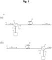
- Fig. 1 is a diagram describing a configuration of a cladding-pumped optical fiber amplifier (300a, 300b).
- a pumping light combiner 12 that multiplexes pumping light Le is connected to one end of a pumping optical fiber 13 doped with a rare earth element, and amplifies signal light Ls guided through a core.
- the amplified signal light is displayed as "Lsa”. Note that while it is typical that an isolator is connected to another end of the pumping optical fiber 13 in accordance with a propagation direction of the signal light Ls, the isolator is omitted in this drawing.
- a residual pumping light remover may be installed to emit the pumping light Le not absorbed by an amplification optical fiber 13 to the outside of the pumping optical fiber 13.
- Figs. 1(a) and 1(b) illustrate a forward pumping type in which the pumping light Le enters an input side of the signal light Ls and a backward pumping type in which the pumping light Le enters an output side of the amplified signal light Lsa, respectively.
- the pumping light Le output from a pumping light source 11 is propagated to the pumping light combiner 12 through a multimode optical fiber 16 having a core diameter of 105 ⁇ m.
- Fig. 2 is a diagram describing a configuration of an optical fiber amplifier (301a, 301b) according to the present embodiment.
- the optical fiber amplifier (301a, 301b) includes:
- the optical fiber amplifier 301a is of a forward pumping type, and the optical fiber amplifier 301b is of a backward pumping type.
- the optical fiber amplifier (301a, 301b) is different from the optical fiber amplifier (300a, 300b) in Fig. 1 in that the core size conversion unit 14 is provided between the pumping light source 11 and the pumping light combiner 12.
- the core size conversion unit 14 and the pumping light source 11 are connected by the multimode optical fiber 16-1.
- the core size conversion unit 14 and the pumping light combiner 12 are connected by a multimode optical fiber 16-2.
- Fig. 3 is a diagram describing an example of a configuration of the core size conversion unit 14.
- the core size conversion unit 14 includes a large core portion 31, a down tapered portion 32, and a small core portion 33.
- the large core portion 31 is connected to the multimode optical fiber 16-1
- the small core portion 33 is connected to the multimode optical fiber 16-2.
- Cladding diameters of the multimode optical fiber 16-2 and the small core portion 33 are denoted by Dd1
- core diameters thereof are denoted by Dc1.
- the down tapered portion 32 connects the large core portion 31 and the small core portion 33, and reduces a cladding diameter from Dd0 to Dd1 and a core diameter from Dc0 to Dc1.
- Fig. 3 shows an example of the configuration
- the core size conversion unit 14 may be configured to output the pumping light Le from the multimode optical fiber 16-1 to a space, control a spot size by means of a lens or the like, and get the pumping light entering the multimode optical fiber 16-2.
- Fig. 4 is a diagram illustrating a taper experimental system using a typical multimode optical fiber 140 having a core diameter of 105 ⁇ m and an NA of 0.22 connected to a pumping light source.
- NA is a numerical aperture
- a refractive index of a core is n core
- the multimode optical fiber 140 is covered with a coating 42 having a higher refractive index than that of a core 35 or a cladding 36, and light coupled from the core 35 to the cladding 36 is immediately absorbed by the coating 42 and becomes a loss.
- a coating of an intermediate portion of the multimode optical fiber 140 is removed, and the multimode optical fiber is heated and stretched by a ceramic heater to form a tapered portion 43.
- a pumping light source is connected to one end of the multimode optical fiber 140, pumping light is input, and the pumping light output from another end thereof is received by a power meter to measure transmittance.
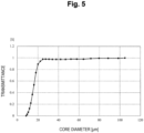
- Fig. 5 is a diagram describing a relationship between a core diameter of a tapered waist portion having the smallest cladding diameter of the tapered portion 43 and transmittance of pumping light. From Fig. 5 , when the core diameter is 20 ⁇ m or more, the transmittance hardly changes, and a value close to 100% is obtained. Since the transmittance rapidly decreases when the core diameter becomes smaller than 20 ⁇ m, it can be seen that a lower limit of the core diameter Dc1 reduced by the taper is 0.19 times the core diameter Dc0 of the multimode optical fiber 16-1. That is, an optical fiber having a typical core diameter Dc0 of 105 ⁇ m, used as the multimode optical fiber 16-1, requires the core diameter Dc1 of the multimode optical fiber 16-2 set to 20 ⁇ m or more.
- Fig. 6 is a diagram describing a structure of the pumping light combiner 12.
- the pumping light combiner 12 includes a port 63a to which the signal light Ls is input and a port 63b to which the pumping light Le is input. These light beams are subjected to wavelength multiplexing by a dichroic mirror 61, lenses 62, and the like, and output to one output port 63c.
- the signal light Ls is guided through each core of the multicore optical fiber 15, and is incident on each core of the amplification optical fiber 13.
- the pumping light Le multimode-propagated through the core of the multimode optical fiber 16-2 is incident on an entire cladding region including the cores of the amplification optical fiber 13.
- a spot size of the pumping light Le can be changed by adjusting the lenses 62 included in the pumping light combiner 12, and the pumping light combiner 12 can also perform a function of the core size conversion unit 14.
- Fig. 7 is a diagram describing a configuration of a cross section of a rare-earth-doped optical fiber which is the amplification optical fiber 13.
- the amplification optical fiber 13 of this configuration includes cores 71 each having a refractive index of n1, a cladding 72 surrounding the cores and having a refractive index of n2, and a resin 73 surrounding the cladding 72 and having a refractive index of n3.
- a relationship between these refractive indexes is as follows.
- n 1 > n 2 > n 3 " ⁇ " represents a center-to-center distance (an inter-core distance) of the cores 71.
- the amplification optical fiber 13 having the two cores 71 is described, but the number of cores of the amplification optical fiber 13 may be three or more.
- the optical fiber 13 when the amplification optical fiber 13 is connected to an output side of the pumping light combiner 12 via an optical fiber, the optical fiber also has the structure of Fig. 7 .
- a coating which is the resin 73 is set to have a lower refractive index than that of the cladding 72.
- pumping light entering a cladding region (a region including both cores 71 and a cladding 72) from the pumping light combiner 12 enters the cladding region of the amplification optical fiber 13.
- Fig. 8 is a diagram describing a configuration of a cross section of a rare-earth-doped optical fiber which is another example of the amplification optical fiber 13.
- the amplification optical fiber 13 of this configuration includes cores 71 each having a refractive index of n1, a cladding 72 surrounding the cores 71 and having a refractive index of n2, an outer cladding 72a surrounding the cladding 72 and having a refractive index of nc, and a coating 74 surrounding the outer cladding 72a and having a refractive index of n4.
- a relationship between these refractive indexes is as follows. n 1 > n 2 > nc
- the amplification optical fiber 13 having the two cores 71 is described, but the number of cores of the amplification optical fiber 13 may be three or more.
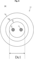
- a diameter of the cladding 72 of the amplification optical fiber 13 having this structure coincides with Dc1 (the core diameters of the small core portion 33 of the core size conversion unit 14 and the multimode optical fiber 16-2). Therefore, the pumping light combiner 12 can cause pumping light having a spot size Dc1 incident from the multimode optical fiber 16-2 to enter the cladding 72.
- n4 may have any refractive index.
- the multimode optical fiber 16-1 having the core diameter of 105 ⁇ m, requires the core diameter Dc1 of the multimode optical fiber 16-2 set to 20 ⁇ m or more (a lower limit of a core reduction ratio that the core size conversion unit 14 has is 0.19). Therefore, the diameter of the cladding 72 of the amplification optical fiber 13, which is Dc1, is 20 ⁇ m or more.
- a diameter of a core wire of an optical fiber defined in the IEC optical fiber standard document IEC 60793-2-60 is 80 ⁇ m at the minimum, and the diameter less than this causes a problem from the viewpoint of handleability and reliability.
- the amplification fiber 13 may have the structure described with reference to Fig. 7 .
- the amplification fiber 13 has the double cladding structure described with reference to Fig. 8 , and the diameter of the outer cladding 72a is set to 80 ⁇ m or more in order to solve the problem in handleability and reliability. That is, when the cladding diameter Dd1 of the multimode optical fiber 16-2 is less than 80 ⁇ m, the core diameter Dc1 of the multimode optical fiber 16-2 is inevitably less than 80 ⁇ m, and the diameter of the cladding 72 of the amplification optical fiber 13 is also less than 80 ⁇ m.
- the diameter of the cladding 72 of the amplification optical fiber 13 in Fig. 8 is as follows. 20 ⁇ m ⁇ Dc1 ⁇ 80 ⁇ m Numerical values within the above are provided under the condition where the core diameter of the multimode optical fiber 16-1 is 105 ⁇ m, and are expressed as ratios thereof to the core diameter of the multimode optical fiber 16-1, each of which is more than 0.19 and less than 0.76.
- the handleability and reliability of the amplification optical fiber 13 can be made equivalent to those of the conventional optical fiber.
- the core diameter (Dc1) of the multimode optical fiber 16-2 is 80 ⁇ m to 105 ⁇ m
- the amplification optical fiber 13 of Fig. 7 may be used, and the diameter of the cladding 72 may be designed to coincide with Dc1.
Landscapes
- Physics & Mathematics (AREA)
- Electromagnetism (AREA)
- Engineering & Computer Science (AREA)
- Plasma & Fusion (AREA)
- Optics & Photonics (AREA)
- Lasers (AREA)
Abstract
Description
- The present disclosure relates to an optical fiber amplifier.
- In an optical fiber communication system, a loss of light propagating through an optical fiber is amplified with an optical amplifier at every fixed distance and relayed to perform long-distance transmission. In the amplification in the optical amplifier, signal light and pumping light for exciting a rare earth element are injected into an amplification optical fiber in which a core region doped with the rare earth element (An erbium-doped optical fiber (EDF), using erbium, is mainly adopted.) (Light with 980 nm or 1480 nm is mainly adopted as the pumping light in a case of EDF), and the signal light is amplified without being converted into electricity.
- In current communication using a single mode optical fiber (SMF), a core pumping type optical amplifier that amplifies signal light propagating through a core by similarly guiding pumping light to the core is used. On the other hand, in recent years, space division multiplexing (SDM) optical fibers using a multi-core fiber having a plurality of cores in a cross section of the optical fiber or a multimode fiber in which two or more modes propagate through the inside of a core, which have been studied in order to expand transmission capacity of optical fibers, have been studied, and optical fiber amplifiers in which a plurality of spatial modes propagates through one of these optical fibers have been studied (See, for example,
Non Patent Literature 1.). - In rivalry with these SDM optical fibers, an SDM optical fiber amplifier for simultaneously amplifying a plurality of spatial modes has been studied, and a cladding-pumped optical fiber amplifier for guiding pumping light to a cladding region of an optical fiber and collectively amplifying a plurality of cores or a plurality of modes, which is different from a core pumping type, has been studied (See, for example, Non
Patent Literature 2.). The cladding-pumped optical fiber amplifier can use a multimode light source, as the pumping light, having power efficiency superior to that of a single mode light source generally used in the core pumping type, and does not always require temperature control by a Peltier element necessary for the single mode light source, and is expected to show that the cladding-pumped optical fiber amplifier exhibits excellent amplification efficiency. As compared with the core pumping type, the cladding-pumped optical fiber amplifier has a problem of a low overlap between a region through which pumping light propagates and a core region doped with a rare earth element, and a problem of a small amount of pumping light absorbed in an amplification optical fiber; However, high amplification efficiency has been established by studies of increasing the amount of pumping light absorbed in the optical fiber by increasing a core cladding ratio Rcc, which is a ratio between a total area of cores in the optical fiber and a cladding area including the core region (See, for example,Non Patent Literature 3.). -
- Non Patent Literature 1: Y. Tsuchida et al., "Amplification characteristics of a multi-core erbium-doped fiber amplifier," in Proc. of OFC2012, paper OM3C.3 (2012)
- Non Patent Literature 2: K. S. Abedin et al., "Cladding-pumped erbium-doped multicore fiber amplifier," Opt. Express, vol. 20, No. 18, pp. 20191-20200 (2012)
- Non Patent Literature 3: T. Sakamoto et al., "Characteristics of Randomly Coupled 12-core Erbium-Doped Fiber Amplifier," J. of Lightw. Technol., vol. 39, no. 4, pp. 1186-1193 (2021)
- In order to increase Rcc, it is preferable that a cladding diameter is small. However, in a configuration of an optical fiber amplifier, an optical fiber connected to a pumping light source is typically a multimode fiber having a core diameter of 105 µm. When such a multimode fiber and a pumping optical fiber having a cladding diameter of 105 µm or less are used, a spot size of the multimode fiber and the cladding diameter of the amplification optical fiber differ in a pumping light combiner, and amplification efficiency decreases due to loss of pumping light.
- For example,
Non Patent Literature 3 discloses that an erbium-doped optical fiber having a cladding diameter of 90 µm is used as an amplification optical fiber, and loss results from difference of a cladding region at a connection point with an optical fiber output from a pumping light combiner. - That is, an SDM optical fiber amplifier has a problem of difference between a spot size of pumping light from a pumping light source and the cladding diameter of the amplification optical fiber in the pumping light combiner, which results in difficulty in increasing amplification efficiency due to loss of the pumping light.
- Therefore, in order to solve the above problem, an object of the present invention is to provide an optical fiber amplifier in which loss of pumping light in a pumping light combiner is reduced to increase amplification efficiency.
- In order to achieve the above object, a core size conversion unit narrowing a core diameter of an optical fiber, through which pumping light from a pumping light source propagates, is arranged in front of a pumping light combiner, and a spot size of the pumping light and a cladding diameter of an amplification optical fiber are equivalent to each other in the pumping light combiner.
- Specifically, an optical fiber amplifier according to the present invention includes:
- an amplification optical fiber having a plurality of cores doped with a rare earth element in a cladding;
- a pumping light source that outputs pumping light for pumping the rare earth element to a multimode optical fiber;
- a core size conversion unit that reduces a diameter of a core of the multimode optical fiber to a diameter of the cladding of the amplification optical fiber; and
- a pumping light combiner that causes signal light propagated through each core of a multicore optical fiber to enter each core of the amplification optical fiber, and causes the pumping light output from the pumping light source and passing through the core size conversion unit to enter the cladding including the cores of the amplification optical fiber.
- By arranging the core size conversion unit, a spot size of the pumping light can be matched with a cladding diameter of the amplification optical fiber in the pumping light combiner, so that loss of the pumping light can be reduced. Furthermore, since the spot size of the pumping light can be made to correspond to an amplification fiber having a small cladding diameter, amplification efficiency can be increased also from the viewpoint of an increase in Rcc. Therefore, the present invention can provide the optical fiber amplifier in which the loss of the pumping light in the pumping light combiner is reduced and the amplification efficiency is increased.
- The amplification optical fiber of the optical fiber amplifier according to the present invention includes a resin on an outer periphery of the cladding, and a relationship among a refractive index n1 of the core, a refractive index n2 of the cladding, and a refractive index n3 of the resin is n1 > n2 > n3.
- The amplification optical fiber of the optical fiber amplifier according to the present invention may include an outer cladding on an outer periphery of the cladding and a coating on an outer periphery of the outer cladding, and a relationship among a refractive index n1 of the core, a refractive index n2 of the cladding, and a refractive index nc of the outer cladding may be n1 > n2 > nc.
- In the optical fiber amplifier according to the present invention, a reduction ratio of the core reduced by the core size conversion unit is preferably larger than 0.19 and smaller than 0.76.
- The present invention can provide an optical fiber amplifier in which loss of pumping light in a pumping light combiner is reduced and amplification efficiency is increased.
-
-
Fig. 1 is a diagram describing a configuration of an optical fiber amplifier. -
Fig. 2 is a diagram describing a configuration of an optical fiber amplifier according to the present invention. -
Fig. 3 is a diagram describing a core size conversion unit of the optical fiber amplifier according to the present invention. -
Fig. 4 is a diagram describing an experimental system. -
Fig. 5 is a diagram describing a relationship between a core diameter and transmittance of pumping light. -
Fig. 6 is a diagram describing a pumping light combiner of the optical fiber amplifier according to the present invention. -
Fig. 7 is a cross-sectional view describing an amplification optical fiber of the optical fiber amplifier according to the present invention. -
Fig. 8 is a cross-sectional view describing an amplification optical fiber of the optical fiber amplifier according to the present invention. - Embodiments of the present invention will be described with reference to the accompanying drawings. The embodiments to be described below are examples of the present invention, and the present invention is not limited to the embodiments to be described below. Note that components assigned the same reference numerals in the present specification and the drawings are the same components.
-
Fig. 1 is a diagram describing a configuration of a cladding-pumped optical fiber amplifier (300a, 300b). A pumping light combiner 12 that multiplexes pumping light Le is connected to one end of a pumpingoptical fiber 13 doped with a rare earth element, and amplifies signal light Ls guided through a core. The amplified signal light is displayed as "Lsa". Note that while it is typical that an isolator is connected to another end of the pumpingoptical fiber 13 in accordance with a propagation direction of the signal light Ls, the isolator is omitted in this drawing. In addition, a residual pumping light remover may be installed to emit the pumping light Le not absorbed by an amplificationoptical fiber 13 to the outside of the pumpingoptical fiber 13.Figs. 1(a) and 1(b) illustrate a forward pumping type in which the pumping light Le enters an input side of the signal light Ls and a backward pumping type in which the pumping light Le enters an output side of the amplified signal light Lsa, respectively. In general, the pumping light Le output from a pumpinglight source 11 is propagated to the pumping light combiner 12 through a multimodeoptical fiber 16 having a core diameter of 105 µm. -
Fig. 2 is a diagram describing a configuration of an optical fiber amplifier (301a, 301b) according to the present embodiment. The optical fiber amplifier (301a, 301b) includes: - an amplification
optical fiber 13 having a plurality of cores doped with a rare earth element in a cladding; - a pumping
light source 11 that outputs pumping light for pumping the rare earth element to a multimode optical fiber 16-1; - a core
size conversion unit 14 that reduces a diameter of a core of the multimode optical fiber 16-1 to a diameter of the cladding of the amplificationoptical fiber 13; and - a pumping
light combiner 12 that causes signal light Ls propagated through each core of a multicoreoptical fiber 15 to enter each core of the amplificationoptical fiber 13, and causes the pumping light Le output from the pumpinglight source 11 and passing through the coresize conversion unit 14 to enter the cladding including the cores of the amplificationoptical fiber 13. - The
optical fiber amplifier 301a is of a forward pumping type, and theoptical fiber amplifier 301b is of a backward pumping type. - The optical fiber amplifier (301a, 301b) is different from the optical fiber amplifier (300a, 300b) in
Fig. 1 in that the coresize conversion unit 14 is provided between the pumpinglight source 11 and the pumpinglight combiner 12. The coresize conversion unit 14 and the pumpinglight source 11 are connected by the multimode optical fiber 16-1. The coresize conversion unit 14 and the pumpinglight combiner 12 are connected by a multimode optical fiber 16-2. -
Fig. 3 is a diagram describing an example of a configuration of the coresize conversion unit 14. The coresize conversion unit 14 includes alarge core portion 31, a down taperedportion 32, and asmall core portion 33. Thelarge core portion 31 is connected to the multimode optical fiber 16-1, and thesmall core portion 33 is connected to the multimode optical fiber 16-2. When cladding diameters of the multimode optical fiber 16-1 and thelarge core portion 31 are denoted by Dd0 and core diameters thereof are denoted by Dc0, Dd0 = 125 µm and Dc0 = 105 µm in general. Cladding diameters of the multimode optical fiber 16-2 and thesmall core portion 33 are denoted by Dd1, and core diameters thereof are denoted by Dc1. The down taperedportion 32 connects thelarge core portion 31 and thesmall core portion 33, and reduces a cladding diameter from Dd0 to Dd1 and a core diameter from Dc0 to Dc1. - Note that
Fig. 3 shows an example of the configuration, and the coresize conversion unit 14 may be configured to output the pumping light Le from the multimode optical fiber 16-1 to a space, control a spot size by means of a lens or the like, and get the pumping light entering the multimode optical fiber 16-2. - The core diameter Dc1 that can be reduced by the core
size conversion unit 14 will be described.Fig. 4 is a diagram illustrating a taper experimental system using a typical multimodeoptical fiber 140 having a core diameter of 105 µm and an NA of 0.22 connected to a pumping light source. When NA is a numerical aperture, a refractive index of a core is ncore, and a refractive index of a cladding is nclad, it is defined as follows.
[Math. 1]
- The multimode
optical fiber 140 is covered with acoating 42 having a higher refractive index than that of a core 35 or acladding 36, and light coupled from the core 35 to thecladding 36 is immediately absorbed by thecoating 42 and becomes a loss. - A coating of an intermediate portion of the multimode
optical fiber 140 is removed, and the multimode optical fiber is heated and stretched by a ceramic heater to form a taperedportion 43. A pumping light source is connected to one end of the multimodeoptical fiber 140, pumping light is input, and the pumping light output from another end thereof is received by a power meter to measure transmittance. -
Fig. 5 is a diagram describing a relationship between a core diameter of a tapered waist portion having the smallest cladding diameter of the taperedportion 43 and transmittance of pumping light. FromFig. 5 , when the core diameter is 20 µm or more, the transmittance hardly changes, and a value close to 100% is obtained. Since the transmittance rapidly decreases when the core diameter becomes smaller than 20 µm, it can be seen that a lower limit of the core diameter Dc1 reduced by the taper is 0.19 times the core diameter Dc0 of the multimode optical fiber 16-1. That is, an optical fiber having a typical core diameter Dc0 of 105 µm, used as the multimode optical fiber 16-1, requires the core diameter Dc1 of the multimode optical fiber 16-2 set to 20 µm or more. -
Fig. 6 is a diagram describing a structure of the pumpinglight combiner 12. The pumpinglight combiner 12 includes aport 63a to which the signal light Ls is input and aport 63b to which the pumping light Le is input. These light beams are subjected to wavelength multiplexing by adichroic mirror 61,lenses 62, and the like, and output to oneoutput port 63c. The signal light Ls is guided through each core of the multicoreoptical fiber 15, and is incident on each core of the amplificationoptical fiber 13. The pumping light Le multimode-propagated through the core of the multimode optical fiber 16-2 is incident on an entire cladding region including the cores of the amplificationoptical fiber 13. - Note that a spot size of the pumping light Le can be changed by adjusting the
lenses 62 included in the pumpinglight combiner 12, and the pumpinglight combiner 12 can also perform a function of the coresize conversion unit 14. -
Fig. 7 is a diagram describing a configuration of a cross section of a rare-earth-doped optical fiber which is the amplificationoptical fiber 13. The amplificationoptical fiber 13 of this configuration includescores 71 each having a refractive index of n1, acladding 72 surrounding the cores and having a refractive index of n2, and aresin 73 surrounding thecladding 72 and having a refractive index of n3. A relationship between these refractive indexes is as follows.
cores 71. - In this drawing, the amplification
optical fiber 13 having the twocores 71 is described, but the number of cores of the amplificationoptical fiber 13 may be three or more. - Note that, when the amplification
optical fiber 13 is connected to an output side of the pumpinglight combiner 12 via an optical fiber, the optical fiber also has the structure ofFig. 7 . Similarly, in the optical fiber, a coating which is theresin 73 is set to have a lower refractive index than that of thecladding 72. In the optical fiber, pumping light entering a cladding region (a region including bothcores 71 and a cladding 72) from the pumpinglight combiner 12 enters the cladding region of the amplificationoptical fiber 13. -
Fig. 8 is a diagram describing a configuration of a cross section of a rare-earth-doped optical fiber which is another example of the amplificationoptical fiber 13. The amplificationoptical fiber 13 of this configuration includescores 71 each having a refractive index of n1, acladding 72 surrounding thecores 71 and having a refractive index of n2, anouter cladding 72a surrounding thecladding 72 and having a refractive index of nc, and acoating 74 surrounding theouter cladding 72a and having a refractive index of n4. A relationship between these refractive indexes is as follows.
- In this drawing, the amplification
optical fiber 13 having the twocores 71 is described, but the number of cores of the amplificationoptical fiber 13 may be three or more. - A diameter of the
cladding 72 of the amplificationoptical fiber 13 having this structure coincides with Dc1 (the core diameters of thesmall core portion 33 of the coresize conversion unit 14 and the multimode optical fiber 16-2). Therefore, the pumpinglight combiner 12 can cause pumping light having a spot size Dc1 incident from the multimode optical fiber 16-2 to enter thecladding 72. - Note that, since the pumping light propagating through a cladding region (a region including both the
cores 71 and the cladding 72) is confined in the cladding region by a refractive index difference from theouter cladding 72a, n4 may have any refractive index. - As described above, in order to improve the amplification efficiency, it is effective to reduce the cladding diameter (increase the Rcc). However, as described in
Fig. 5 , the multimode optical fiber 16-1, having the core diameter of 105 µm, requires the core diameter Dc1 of the multimode optical fiber 16-2 set to 20 µm or more (a lower limit of a core reduction ratio that the coresize conversion unit 14 has is 0.19). Therefore, the diameter of thecladding 72 of the amplificationoptical fiber 13, which is Dc1, is 20 µm or more. - Next, an upper limit of Dc1 will be described. A diameter of a core wire of an optical fiber defined in the IEC optical fiber standard document IEC 60793-2-60 is 80 µm at the minimum, and the diameter less than this causes a problem from the viewpoint of handleability and reliability.
- When the diameter of the
cladding 72 is 80 µm or more, there is no problem in handleability and reliability, and theamplification fiber 13 may have the structure described with reference toFig. 7 . - On the other hand, when the diameter of the
cladding 72 is less than 80 µm in order to improve the Rcc, theamplification fiber 13 has the double cladding structure described with reference toFig. 8 , and the diameter of theouter cladding 72a is set to 80 µm or more in order to solve the problem in handleability and reliability. That is, when the cladding diameter Dd1 of the multimode optical fiber 16-2 is less than 80 µm, the core diameter Dc1 of the multimode optical fiber 16-2 is inevitably less than 80 µm, and the diameter of thecladding 72 of the amplificationoptical fiber 13 is also less than 80 µm. - As described above, it is preferable that the diameter of the
cladding 72 of the amplificationoptical fiber 13 inFig. 8 is as follows.
- If the diameter of the
outer cladding 72a is, for example, 80 µm to 125 µm, the handleability and reliability of the amplificationoptical fiber 13 can be made equivalent to those of the conventional optical fiber. - On the other hand, when the core diameter (Dc1) of the multimode optical fiber 16-2 is 80 µm to 105 µm, the amplification
optical fiber 13 ofFig. 7 may be used, and the diameter of thecladding 72 may be designed to coincide with Dc1. -
- 11
- Pumping light source
- 12
- Pumping light combiner
- 13
- Amplification optical fiber
- 14
- Core size conversion unit
- 15
- Multicore optical fiber
- 16, 16-1, 16-2
- Multimode optical fiber
- 31
- Large core portion
- 32
- Down tapered portion
- 33
- Small core portion
- 35
- Core
- 36
- Cladding
- 42
- Coating
- 43
- Tapered portion
- 61
- Dichroic mirror
- 62
- Lens
- 63a, 63b, 63c
- Port
- 71
- Core
- 72
- Cladding
- 72a
- Outer cladding
- 73
- Resin
- 74
- Coating
- 140
- Multimode optical fiber
- 301a, 301b
- Optical fiber amplifier
Claims (4)
- An optical fiber amplifier comprising:an amplification optical fiber having a plurality of cores doped with a rare earth element in a cladding;a pumping light source that outputs pumping light for pumping the rare earth element to a multimode optical fiber;a core size conversion unit that reduces a diameter of a core of the multimode optical fiber to a diameter of the cladding of the amplification optical fiber; anda pumping light combiner that causes signal light propagated through each core of a multicore optical fiber to enter each core of the amplification optical fiber, and causes the pumping light output from the pumping light source and passing through the core size conversion unit to enter the cladding including the cores of the amplification optical fiber.
- The optical fiber amplifier according to claim 1, whereinthe amplification optical fiber includes a resin on an outer periphery of the cladding, anda relationship among a refractive index n1 of the core, a refractive index n2 of the cladding, and a refractive index n3 of the resin is n1 > n2 > n3.
- The optical fiber amplifier according to claim 1, whereinthe amplification optical fiber includes an outer cladding on an outer periphery of the cladding and a coating on an outer periphery of the outer cladding, anda relationship among a refractive index n1 of the core, a refractive index n2 of the cladding, and a refractive index nc of the outer cladding is n1 > n2 > nc.
- The optical fiber amplifier according to any one of claims 1 to 3, wherein a reduction ratio of the core reduced by the core size conversion unit is larger than 0.19 and smaller than 0.76.
Applications Claiming Priority (1)
| Application Number | Priority Date | Filing Date | Title |
|---|---|---|---|
| PCT/JP2022/017359 WO2023195155A1 (en) | 2022-04-08 | 2022-04-08 | Optical fiber amplifier |
Publications (2)
| Publication Number | Publication Date |
|---|---|
| EP4507140A1 true EP4507140A1 (en) | 2025-02-12 |
| EP4507140A4 EP4507140A4 (en) | 2026-03-25 |
Family
ID=88242792
Family Applications (1)
| Application Number | Title | Priority Date | Filing Date |
|---|---|---|---|
| EP22936553.1A Pending EP4507140A4 (en) | 2022-04-08 | 2022-04-08 | FIBER OPTIC AMPLIFIER |
Country Status (4)
| Country | Link |
|---|---|
| US (1) | US20250210929A1 (en) |
| EP (1) | EP4507140A4 (en) |
| JP (1) | JP7798181B2 (en) |
| WO (1) | WO2023195155A1 (en) |
Family Cites Families (14)
| Publication number | Priority date | Publication date | Assignee | Title |
|---|---|---|---|---|
| US6882664B2 (en) * | 2002-02-28 | 2005-04-19 | Lucent Technologies Inc. | Laser with internally coupled pump source |
| JP2007294534A (en) * | 2006-04-21 | 2007-11-08 | Sumitomo Electric Ind Ltd | Optical module |
| WO2010057288A1 (en) * | 2008-11-21 | 2010-05-27 | Coractive High-Tech Inc. | Pump combiner including a multi-clad waveguide |
| JP2011035012A (en) * | 2009-07-29 | 2011-02-17 | Fujikura Ltd | Fiber laser device |
| JP5269827B2 (en) * | 2010-03-20 | 2013-08-21 | 株式会社フジクラ | Holey fiber and laser device using the same |
| JP2011228541A (en) * | 2010-04-21 | 2011-11-10 | Photonic Science Technology Inc | Method of manufacturing tapered optical fiber |
| JP2012104748A (en) * | 2010-11-12 | 2012-05-31 | Fujikura Ltd | Optical fiber amplifier and fiber laser device using the optical fiber amplifier |
| JP5643632B2 (en) * | 2010-12-16 | 2014-12-17 | 株式会社フジクラ | Multi-port coupler, and optical fiber amplifier, fiber laser apparatus and resonator using the same |
| JP2015510253A (en) * | 2011-12-13 | 2015-04-02 | オーエフエス ファイテル,エルエルシー | Multi-core erbium-doped fiber amplifier |
| JP2014192466A (en) * | 2013-03-28 | 2014-10-06 | Furukawa Electric Co Ltd:The | Fiber structure and optical fiber connection structure |
| JP6181682B2 (en) * | 2015-02-20 | 2017-08-16 | 株式会社フジクラ | Optical device |
| US10581216B2 (en) * | 2016-05-25 | 2020-03-03 | Nec Corporation | 3D waveguide for efficient coupling of multimode pump and signals to a multicore fiber amplifier |
| JP6668272B2 (en) * | 2017-01-27 | 2020-03-18 | 株式会社フジクラ | Optical fiber for amplification |
| JP7164026B2 (en) * | 2019-04-08 | 2022-11-01 | 日本電気株式会社 | Optical amplification device, optical transmission system, and optical amplification method |
-
2022
- 2022-04-08 JP JP2024513665A patent/JP7798181B2/en active Active
- 2022-04-08 EP EP22936553.1A patent/EP4507140A4/en active Pending
- 2022-04-08 WO PCT/JP2022/017359 patent/WO2023195155A1/en not_active Ceased
- 2022-04-08 US US18/851,161 patent/US20250210929A1/en active Pending
Also Published As
| Publication number | Publication date |
|---|---|
| EP4507140A4 (en) | 2026-03-25 |
| WO2023195155A1 (en) | 2023-10-12 |
| JP7798181B2 (en) | 2026-01-14 |
| JPWO2023195155A1 (en) | 2023-10-12 |
| US20250210929A1 (en) | 2025-06-26 |
Similar Documents
| Publication | Publication Date | Title |
|---|---|---|
| US8094370B2 (en) | Cladding pumped fibre laser with a high degree of pump isolation | |
| US6434295B1 (en) | Side coupled pumping of double clad fiber gain media | |
| US7046432B2 (en) | Optical fiber coupling arrangement | |
| US7649914B2 (en) | Optical fibre laser | |
| EP1950852A2 (en) | High power optical apparatus employing large-mode-area, multimode, gain-producing optical fibers | |
| US20110279888A1 (en) | Multicore transmission and amplifier fibers and schemes for launching pump light to amplifier cores | |
| Tsuchida et al. | Cladding pumped seven-core EDFA using an absorption-enhanced erbium doped fibre | |
| WO2013051655A1 (en) | Multi-core amplified optical fiber and multi-core optical fiber amplifier | |
| CN110265858A (en) | High-power Raman fiber laser system for selectively exciting high-order mode | |
| US12248171B2 (en) | Multi-core optical amplifying fiber, multi-core optical fiber amplifier, and optical communication system | |
| JP7214527B2 (en) | multicore optical amplifying fiber, multicore optical fiber amplifier and optical communication system | |
| KR20080052237A (en) | Gain Fixed Optical Amplifier with Double Clad Structure | |
| EP2625753B1 (en) | High power neodymium fiber lasers and amplifiers | |
| JP4269453B2 (en) | Optical fiber for optical amplification and optical fiber amplifier | |
| CN112612076A (en) | Few-mode multi-core microstructure optical fiber and few-mode optical fiber amplifier | |
| US20220337025A1 (en) | Optical amplifier | |
| US8363310B2 (en) | High power and high gain fiber amplifier | |
| Takasaka et al. | Cladding pump recycling device for 19-core edfa | |
| US20250210929A1 (en) | Fiber amplifier | |
| EP4686015A1 (en) | Rare earth-doped fiber, optical amplifier, and design method of rare earth-doped fiber | |
| US20250105578A1 (en) | Optical fiber for amplification, optical amplifier, and method for controlling optical amplifier | |
| US20010043388A1 (en) | High order mode erbium-doped fiber amplifier | |
| US20220344888A1 (en) | Amplification fiber and optical amplifier | |
| Zhang et al. | Ultra-low-loss all-fiber 976/1550 nm few-mode pumping/signal multiplexer for four-mode Erbium-doped fiber amplifier | |
| EP4597183A1 (en) | High beam quality optical fiber combiner for multiwavelength signal delivering |
Legal Events
| Date | Code | Title | Description |
|---|---|---|---|
| STAA | Information on the status of an ep patent application or granted ep patent |
Free format text: STATUS: THE INTERNATIONAL PUBLICATION HAS BEEN MADE |
|
| PUAI | Public reference made under article 153(3) epc to a published international application that has entered the european phase |
Free format text: ORIGINAL CODE: 0009012 |
|
| STAA | Information on the status of an ep patent application or granted ep patent |
Free format text: STATUS: REQUEST FOR EXAMINATION WAS MADE |
|
| 17P | Request for examination filed |
Effective date: 20240917 |
|
| AK | Designated contracting states |
Kind code of ref document: A1 Designated state(s): AL AT BE BG CH CY CZ DE DK EE ES FI FR GB GR HR HU IE IS IT LI LT LU LV MC MK MT NL NO PL PT RO RS SE SI SK SM TR |
|
| DAV | Request for validation of the european patent (deleted) | ||
| DAX | Request for extension of the european patent (deleted) | ||
| RAP3 | Party data changed (applicant data changed or rights of an application transferred) |
Owner name: NTT, INC. |
|
| A4 | Supplementary search report drawn up and despatched |
Effective date: 20260225 |
|
| RIC1 | Information provided on ipc code assigned before grant |
Ipc: H01S 3/067 20060101AFI20260219BHEP Ipc: H01S 3/10 20060101ALI20260219BHEP Ipc: H01S 3/094 20060101ALI20260219BHEP |