EP4507137A1 - Coaxial cable connector - Google Patents
Coaxial cable connector Download PDFInfo
- Publication number
- EP4507137A1 EP4507137A1 EP24192956.1A EP24192956A EP4507137A1 EP 4507137 A1 EP4507137 A1 EP 4507137A1 EP 24192956 A EP24192956 A EP 24192956A EP 4507137 A1 EP4507137 A1 EP 4507137A1
- Authority
- EP
- European Patent Office
- Prior art keywords
- contact
- axis direction
- connector
- direction side
- internal housing
- Prior art date
- Legal status (The legal status is an assumption and is not a legal conclusion. Google has not performed a legal analysis and makes no representation as to the accuracy of the status listed.)
- Pending
Links
Images






Classifications
-
- H—ELECTRICITY
- H01—ELECTRIC ELEMENTS
- H01R—ELECTRICALLY-CONDUCTIVE CONNECTIONS; STRUCTURAL ASSOCIATIONS OF A PLURALITY OF MUTUALLY-INSULATED ELECTRICAL CONNECTING ELEMENTS; COUPLING DEVICES; CURRENT COLLECTORS
- H01R13/00—Details of coupling devices of the kinds covered by groups H01R12/70 or H01R24/00 - H01R33/00
- H01R13/646—Details of coupling devices of the kinds covered by groups H01R12/70 or H01R24/00 - H01R33/00 specially adapted for high-frequency, e.g. structures providing an impedance match or phase match
- H01R13/6473—Impedance matching
-
- H—ELECTRICITY
- H01—ELECTRIC ELEMENTS
- H01R—ELECTRICALLY-CONDUCTIVE CONNECTIONS; STRUCTURAL ASSOCIATIONS OF A PLURALITY OF MUTUALLY-INSULATED ELECTRICAL CONNECTING ELEMENTS; COUPLING DEVICES; CURRENT COLLECTORS
- H01R24/00—Two-part coupling devices, or either of their cooperating parts, characterised by their overall structure
- H01R24/38—Two-part coupling devices, or either of their cooperating parts, characterised by their overall structure having concentrically or coaxially arranged contacts
- H01R24/40—Two-part coupling devices, or either of their cooperating parts, characterised by their overall structure having concentrically or coaxially arranged contacts specially adapted for high frequency
- H01R24/42—Two-part coupling devices, or either of their cooperating parts, characterised by their overall structure having concentrically or coaxially arranged contacts specially adapted for high frequency comprising impedance matching means or electrical components, e.g. filters or switches
- H01R24/44—Two-part coupling devices, or either of their cooperating parts, characterised by their overall structure having concentrically or coaxially arranged contacts specially adapted for high frequency comprising impedance matching means or electrical components, e.g. filters or switches comprising impedance matching means
-
- H—ELECTRICITY
- H01—ELECTRIC ELEMENTS
- H01R—ELECTRICALLY-CONDUCTIVE CONNECTIONS; STRUCTURAL ASSOCIATIONS OF A PLURALITY OF MUTUALLY-INSULATED ELECTRICAL CONNECTING ELEMENTS; COUPLING DEVICES; CURRENT COLLECTORS
- H01R13/00—Details of coupling devices of the kinds covered by groups H01R12/70 or H01R24/00 - H01R33/00
- H01R13/646—Details of coupling devices of the kinds covered by groups H01R12/70 or H01R24/00 - H01R33/00 specially adapted for high-frequency, e.g. structures providing an impedance match or phase match
- H01R13/6473—Impedance matching
- H01R13/6477—Impedance matching by variation of dielectric properties
-
- H—ELECTRICITY
- H01—ELECTRIC ELEMENTS
- H01R—ELECTRICALLY-CONDUCTIVE CONNECTIONS; STRUCTURAL ASSOCIATIONS OF A PLURALITY OF MUTUALLY-INSULATED ELECTRICAL CONNECTING ELEMENTS; COUPLING DEVICES; CURRENT COLLECTORS
- H01R9/00—Structural associations of a plurality of mutually-insulated electrical connecting elements, e.g. terminal strips or terminal blocks; Terminals or binding posts mounted upon a base or in a case; Bases therefor
- H01R9/03—Connectors arranged to contact a plurality of the conductors of a multiconductor cable, e.g. tapping connections
- H01R9/05—Connectors arranged to contact a plurality of the conductors of a multiconductor cable, e.g. tapping connections for coaxial cables
- H01R9/0512—Connections to an additional grounding conductor
-
- H—ELECTRICITY
- H01—ELECTRIC ELEMENTS
- H01R—ELECTRICALLY-CONDUCTIVE CONNECTIONS; STRUCTURAL ASSOCIATIONS OF A PLURALITY OF MUTUALLY-INSULATED ELECTRICAL CONNECTING ELEMENTS; COUPLING DEVICES; CURRENT COLLECTORS
- H01R2201/00—Connectors or connections adapted for particular applications
- H01R2201/26—Connectors or connections adapted for particular applications for vehicles
Definitions
- the present disclosure relates to a coaxial cable connector.
- a spatial layer is formed in a crimp part between a contact and a copper wire.
- Such a spatial layer containing air causes an increase in impedance and deterioration of matching with design impedance.
- the present disclosure has been accomplished to solve the above problem, and an object of the present disclosure is thus to provide a coaxial cable connector with improved impedance matching.
- a coaxial cable connector is a coaxial cable connector including a connector for relaying a cable, the connector including a contact containing a conductor, an insulator body containing an insulator and supporting the contact, and an impedance adjuster having a part incorporated into the insulator body and containing the conductor, wherein the impedance adjuster covers an exposed part of a core wire of the cable connected to the contact, the exposed part being exposed from the insulator body.
- the connector may further include a GND shell containing the conductor, the contact, the insulator body, and the impedance adjuster may be disposed inside the GND shell, and the impedance adjuster is disposed in a spatial layer formed between the exposed part and the GND shell.
- the impedance adjuster may have a tube shape with a center axis located at the contact and the core wire.
- the cable may include the core wire containing the conductor, a coating having a part covering the core wire and containing the insulator, a shield having a part covering the coating and containing the conductor, and an outside cover having a part covering the shield and containing the insulator, and the impedance adjuster may cover an end of the coating.
- the impedance adjuster may be incorporated into the insulator body by insert molding.
- the impedance adjuster may be incorporated into the insulator body by being press-fit to the insulator body.
- the impedance adjuster may be electrically connected to the GND shell.
- the impedance adjuster may be electrically isolated from the GND shell, the contact, and the core wire.
- a coaxial cable connector is a coaxial cable connector including a first connector and a second connector for relaying a first cable and a second cable
- the first connector includes a first contact containing a conductor and including a projection at one end, a first insulator body containing an insulator and supporting the first contact, and a first impedance adjuster having a part incorporated into the first insulator body and containing the conductor
- the first impedance adjuster covers an exposed part of a first core wire of the first cable connected to another end of the first contact, the exposed part being exposed from the first insulator body
- the second connector includes a second contact containing the conductor and including a recess at one end, a second insulator body containing the insulator and supporting the second contact, and a second impedance adjuster having a part incorporated into the second insulator body and containing the conductor
- the second impedance adjuster covers an exposed part of a second core wire of the second cable connected
- a coaxial cable connector according to this embodiment will be described.
- a relay connector device that relays a cable will be described as an example of the coaxial cable connector according to this embodiment.
- the coaxial cable connector according to this embodiment is not limited to the relay connector device, and it may include another connector device such as a coaxial connector device where a cable mates with a board as long as it is configured to connect a coaxial cable.
- a relay connector device according to a comparative example will be described for comparison. This will clarify the features of the relay connector device according to the first embodiment.
- Fig. 1 is a sectional view illustrating a relay connector device 10 according to a comparative example.
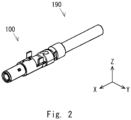
- Fig. 2 is a perspective view illustrating a connector 100 in the relay connector device 10 according to the comparative example.
- Fig. 3 is a perspective view illustrating a connector 200 in the relay connector device 10 according to the comparative example.
- an external housing is omitted. Note that the relay connector device 10 may be used in separation from the external housing.
- the relay connector device 10 includes the connector 100 and the connector 200.
- the connector 100 is the connector 100 on the male side, for example, and the connector 200 is the connector 200 on the female side, for example.
- the connector 100 is connected to an end of a cable 190.
- the connector 200 is connected to an end of a cable 290.
- the connector 100 is connected to the connector 200.
- the relay connector device 10 thereby relays the cable 190 and the cable 290.
- the xyz-orthogonal coordinate axis system is used.
- x axis direction an axial direction that is coaxial with the relay connector device 10 or the like.
- a direction where the connector 100 on the male side is headed to the connector 200 on the female side when connecting the connector 100 and the connector 200 is referred to as +x direction.
- Two directions orthogonal to the x axis are referred to as y axis direction and z axis direction.
- Fig. 4 is an exploded perspective view illustrating each member constituting the connector 100 in the relay connector device 10 according to the comparative example.
- Fig. 5 is a perspective view illustrating an internal housing 130 in the relay connector device 10 according to the comparative example.
- the connector 100 includes a GND shell 110, a GND shell 120, an internal housing 130, a contact 140, a sleeve 150, and an external housing 180. Each member is described hereinbelow.
- the GND shell 110 and the GND shell 120 contain a conductor as a material.
- the GND shell 110 and the GND shell 120 contain a metal as a material.
- the GND shell 110 and the GND shell 120 may contain a material other than a metal as long as it contains a conductor.
- the GND shell 110 and the GND shell 120 are electrically connected to a ground potential.
- the GND shell 110 and the GND shell 120 have a tube shape.
- the GND shell 110 and the GND shell 120 have a cylindrical shape.
- the GND shell 110 and the GND shell 120 are disposed in such a way that their center axes are in the x axis direction.
- the center axes of the GND shell 110 and the GND shell 120 coincide with each other.
- the GND shell 110 is disposed on the +x axis direction side of the GND shell 120.
- the GND shell 110 may partly overlap the GND shell 120.
- a part of the GND shell 110 on the -x axis direction side overlaps a part of the GND shell 120 on the +x axis direction side.
- the GND shell 110 and the GND shell 120 integrally have a cylindrical shape.
- the internal housing 130 and the contact 140 are disposed inside the GND shell 110 and the GND shell 120.
- the sleeve 150 and a part of the cable 190 may be disposed inside the GND shell 120.
- the internal housing 130 may be press-fit to the inside of the GND shell 110.
- An end of the GND shell 110 on the +x axis direction side is disposed in close proximity to an end of the internal housing 130 on the +x axis direction side.
- the position on the x axis of the end of the GND shell 110 on the +x axis direction side may coincide with that of the end of the internal housing 130 on the +x axis direction side.
- An end of the GND shell 120 on the -x axis direction side is located above an outside cover 194 of the cable 190.
- the end of the GND shell 120 on the -x axis direction side is disposed in close proximity to an end of the sleeve 150 on the -x axis direction side.
- the position on the x axis of the end of the GND shell 120 on the -x axis direction side may coincide with that of the end of the sleeve 150 on the -x axis direction side.
- the internal housing 130 contains an insulator as a material.
- the internal housing 130 is also called an insulator body.
- the internal housing 130 contains a resin as a material.
- the internal housing 130 may contain a material other than a resin as long as it contains an insulator.
- the internal housing 130 has a tube shape.
- the internal housing 130 has a cylindrical shape.
- the internal housing 130 is disposed in such a way that its center axis is in the x axis direction.
- the internal housing 130 is disposed inside the GND shell 110.
- the contact 140 is disposed inside the internal housing 130.
- the internal housing 130 supports the contact 140.
- the contact 140 disposed inside the internal housing 130 may be press-fit into the internal housing 130.
- the internal housing 130 has a recess 131 in its end surface on the +x axis direction side.
- An end of the contact 140 on the +x axis direction side projects from a bottom surface of the recess 131.
- One end of the contact 140 on the +x axis direction side includes a projection 141.
- a side wall of the recess 131 of the internal housing 130 surrounds the end of the contact 140 on the +x axis direction side.
- An end of the internal housing 130 on the -x axis direction side is located in close proximity to an end of the contact 140 on the -x axis direction side.
- the position on the x axis of the end of the internal housing 130 on the -x axis direction side may coincide with that of another end of the contact 140 on the -x axis direction side.
- a core wire 191 of the cable 190 is connected to the end of the contact 140 on the -x axis direction side.
- a connection part between the contact 140 and the core wire 191 of the cable 190 may be disposed inside the internal housing 130.
- the contact 140 contains a conductor as a material.
- the contact 140 contains a metal as a material.
- the contact 140 may contain a material other than a metal as long as it contains a conductor.
- the contact 140 serves as a transmission path of a high-frequency signal, for example.
- the contact 140 has a bar shape.
- the contact 140 is disposed in such a way that its center axis is in the x axis direction.
- the contact 140 has the projection 141 at one end on the +x axis direction side.
- the contact 140 is disposed inside the internal housing 130.
- the other end of the contact 140 on the -x axis direction side is connected to the core wire 191 of the cable 190.
- the projection 141 at one end of the contact 140 on the +x axis direction side is connected to a contact 240 of the connector 200 on the female side.
- the projection 141 of the contact 140 has a projecting shape to mate with a recess 241 of the contact 240.
- the sleeve 150 contains a conductor as a material.
- the sleeve 150 contains a metal as a material.
- the sleeve 150 may contain a material other than a metal as long as it contains a conductor.
- the sleeve 150 has a tube shape.
- the sleeve 150 has a cylindrical shape.
- the sleeve 150 is disposed in such a way that its center axis is in the x axis direction.
- the sleeve 150 includes a first part 151 in cylindrical shape and a second part 152 in cylindrical shape.
- the first part 151 and the second part 152 are connected in parallel in the x axis direction.
- the first part 151 is disposed on the +x axis direction side of the second part 152.
- the outside diameter of the first part 151 is smaller than the outside diameter of the second part 152.
- the inside diameter of the first part 151 is smaller than the inside diameter of the second part 152.
- the first part 151 is disposed inside the GND shell 120.
- the first part 151 covers a shield 193 that is exposed from an end of the outside cover 194 of the cable 190.
- the second part 152 covers the outside cover 194 of the cable 190.
- a connection part between the first part 151 and the second part 152 is located in close proximity to an end of the outside cover 194 on the +x axis direction side.
- the external housing 180 contains an insulator as a material.
- the external housing 180 contains a resin as a material.
- the external housing 180 may contain a material other than a resin as long as it contains an insulator.
- the external housing 180 has a tube shape.
- the external housing 180 has a square tube shape.
- the external housing 180 is disposed in such a way that its center axis is in the x axis direction.
- An assembly of the GND shell 110, the GND shell 120, the internal housing 130, the contact 140, and the sleeve 150 is mounted inside the external housing 180.
- the structure of the cable 190 is described hereinafter.
- the cable 190 extends in one direction and has flexibility.
- the cable 190 includes the core wire 191, a coating 192, a shield 193, and the outside cover 194.
- the core wire 191, the coating 192, the shield 193, and the outside cover 194 are disposed in concentric layers. Those members are stacked concentrically with the core wire 191 at the center. When the cable 190 extends in the x axis direction, those members are stacked concentrically with their center axes in the x axis direction.
- the coating 192 covers a side surface of the core wire 191.
- the shield 193 covers a side surface of the coating 192.
- the outside cover 194 covers a side surface of the shield 193.
- the core wire 191 contains a conductor as a material.
- the core wire 191 has a linear shape.
- the core wire 191 may contain a copper wire, for example.
- the core wire 191 may contain a material other than a copper wire as long as it contains a linear conductor.
- a part of the core wire 191 on the +x axis direction side projects from an end of the coating 192 on the +x axis direction side.
- the coating 192 contains an insulator as a material.
- the coating 192 contains a resin as a material.
- the coating 192 may contain a material other than a resin as long as it contains an insulator.
- the coating 192 has a tube shape.
- the coating 192 has a part that covers the side surface of the core wire 191.
- the end of the coating 192 on the +x axis direction side may be a cut surface.
- a part of the coating 192 on the +x axis direction side may be exposed from an end of the shield 193 on the +x axis direction side.
- the shield 193 contains a conductor as a material.
- the shield 193 may contain a metal.
- the shield 193 may contain a material other than a metal as long as it contains a conductor.
- the shield 193 has a tube shape.
- the shield 193 has a part that covers the side surface of the coating 192.
- the end of the shield 193 on the +x axis direction side is folded to the -x axis direction side.
- the end of the shield 193 on the +x axis direction side is folded to the -x axis direction side along an edge of the first part 151 of the sleeve 150 on the +x axis direction side.
- the end of the folded shield 193 on the +x axis direction side is connected to an inner surface of the GND shell 120.
- the shield 193 is electrically connected to the ground potential.
- a part of the shield 193 on the +x axis direction side may be exposed from an end of the outside cover 194 on the +x axis direction side.
- the outside cover 194 contains an insulator as a material.
- the outside cover 194 may contain a resin.
- the outside cover 194 may contain a material other than a resin as long as it contains an insulator.
- the outside cover 194 has a tube shape.
- the outside cover 194 has a part that covers the side surface of the shield 193.
- the end of the outside cover 194 on the +x axis direction side may be a cut surface.
- a part of the outside cover 194 on the +x axis direction side may be covered with at least any one of the sleeve 150 and the GND shell 120.
- Fig. 6 is an exploded perspective view illustrating each member constituting the connector 200 in the relay connector device 10 according to the comparative example.
- Fig. 7 is a perspective view illustrating an internal housing 230 in the relay connector device 10 according to the comparative example.
- the connector 200 includes a GND shell 210, a GND shell 220, an internal housing 230, a contact 240, a sleeve 250, and an external housing 280.
- the cable 190 is located on the -x axis direction side of the connector 100
- the cable 290 is located on the +x axis direction side of the connector 200.
- the basic structures and functions of the GND shell 210, the GND shell 220, the internal housing 230, the contact 240, the sleeve 250, and the external housing 280 of the connector 200 are the same as the structures and functions of the GND shell 110, the GND shell 120, the internal housing 130, the contact 140, the sleeve 150, and the external housing 180 of the connector 100, respectively.
- the GND shell 210 is disposed on the -x axis direction side of the GND shell 220.
- the internal housing 230 and the contact 240 are disposed inside the GND shell 210 and the GND shell 220.
- the sleeve 250 and the cable 290 may be disposed inside the GND shell 220.
- the internal housing 230 may be press-fit to the inside of the GND shell 210.
- An end of the GND shell 210 on the -x axis direction side is disposed in close proximity to an end of the internal housing 230 on the -x axis direction side.
- the position on the x axis of the end of the GND shell 210 on the -x axis direction side may coincide with that of the end of the internal housing 230 on the -x axis direction side.
- An end of the GND shell 220 on the +x axis direction side is located above an outside cover 294 of the cable 290.
- the end of the GND shell 220 on the +x axis direction side is disposed in close proximity to an end of the sleeve 250 on the +x axis direction side.
- the position on the x axis of the end of the GND shell 220 on the +x axis direction side may coincide with that of the end of the sleeve 250 on the +x axis direction side.
- the internal housing 230 is disposed inside the GND shell 210.
- the contact 240 is disposed inside the internal housing 230.
- the contact 240 is disposed inside the GND shell 210.
- the internal housing 230 supports the contact 240.
- the internal housing 230 includes a first part 231 and a second part 232.
- the first part 231 is disposed on the -x axis direction side of the second part 232.
- the first part 231 and the second part 232 have a cylindrical shape whose center axis coincides with the center axis of the internal housing 230.
- the outside diameter of the first part 231 is smaller than the outside diameter of the second part 232.
- the first part 231 mates with the recess 131 of the internal housing 130 of the connector 100. When the first part 231 mates with the recess 131, the projection 141 of the contact 140 of the connector 100 mates with the recess 241 of the contact 240 of the connector 200.
- An end of the internal housing 230 on the -x axis direction side is an end surface of the first part 231 on the -x axis direction side.
- the end of the internal housing 230 on the -x axis direction side is disposed in close proximity to an end of the GND shell 210 on the -x axis direction side.
- the position on the x axis of the end of the internal housing 230 on the -x axis direction side may coincide with that of the end of the GND shell 210 on the -x axis direction side.
- the recess 241 on the -x axis direction side of the contact 240 is disposed inside the first part 231.
- An end of the internal housing 230 on the +x axis direction side is disposed in close proximity to an end of the contact 240 on the +x axis direction side.
- the position on the x axis of the end of the internal housing 230 on the +x axis direction side may coincide with that of another end of the contact 240 on the +x axis direction side.
- a core wire 291 of the cable 290 is connected to the end of the contact 240 on the +x axis direction side.
- a connection part between the contact 240 and the core wire 291 of the cable 290 may be disposed inside the internal housing 230.
- the contact 240 has the recess 241 at one end on the -x axis direction side.
- the contact 240 is disposed inside the internal housing 230.
- An end of the contact 240 on the +x axis direction side is connected to the core wire 291 of the cable 290.
- the projection 141 of the contact 140 mates with the recess 241 of the contact 240.
- the sleeve 250 includes a first part 251 in cylindrical shape and a second part 252 in cylindrical shape.
- the first part 251 is disposed on the -x axis direction side of the second part 252.
- the outside diameter of the first part 251 is smaller than the outside diameter of the second part 252.
- the inside diameter of the first part 251 is smaller than the inside diameter of the second part 252.
- the first part 251 is disposed inside the GND shell 220.
- the first part 251 covers a shield 293 that is exposed from an end of the outside cover 294 of the cable 290.
- the second part 252 covers the outside cover 294 of the cable 290.
- a connection part between the first part 251 and the second part 252 is thus located in close proximity to an end of the outside cover 294.
- the cable 290 includes the core wire 291, a coating 292, the shield 293, and the outside cover 294.
- the structures and functions of the core wire 291, the coating 292, the shield 293, and the outside cover 294 in the cable 290 are the same as the structures and functions of the core wire 191, the coating 192, the shield 193, and the outside cover 194 in the cable 190, respectively.
- the direction in which the core wire 291 connects to the contact 240, the direction of the end surface of the coating 292 having the cut surface, the direction of the end of the shield 293 and the direction in which it is folded, the direction of the end surface of the outside cover 294 and the like are opposite to those in the cable 190.
- Fig. 8 is a sectional view illustrating the operation of connecting the connectors 100 and 200 in the relay connector device according to the comparative example.
- the connector 100 and the connector 200 are opposed to each other.
- the projection 141 of the contact 140 mates with the recess 241 of the contact 240.
- a transmission path of a high-frequency signal is thereby formed between the contact 140 and the contact 240.
- the first part 231 of the internal housing 230 may mate with the recess 131 of the internal housing 130.
- the GND shell 110 and the GND shell 210 come into contact with each other.
- a shield that covers the transmission path of a high-frequency signal is thereby formed.
- a spatial layer 195 is formed between the core wire 191 and the GND shells 110 and 120 in a region from a connection part between the other end of the contact 140 on the -x axis direction side and the end of the core wire 191 on the +x axis direction side to the end of the coating 192 of the cable 190 on the +x axis direction side.
- the spatial layer 195 is formed between an exposed part of the core wire 191 connected to the contact 140, which is exposed from the internal housing 130 and the coating 192, and the GND shells 110 and 120.
- a spatial layer 295 is formed between the core wire 291 and the GND shells 210 and 220 in a region from a connection part between the other end of the contact 240 on the +x axis direction side and the end of the core wire 291 on the -x axis direction side to the end of the coating 292 of the cable 290 on the -x axis direction side.
- the spatial layer 295 is formed between an exposed part of the core wire 291 connected to the contact 240, which is exposed from the internal housing 230 and the coating 292, and the GND shells 210 and 220.
- the spatial layers 195 and 295 that contain air are formed near a connection part of the contacts 140 and 240. Due to the existence of the spatial layers 195 and 295, the impedance of the relay connector device 10 increases. This makes it difficult to improve the matching with design impedance.
- One approach to reduce the impedance near the spatial layers 195 and 295 is deforming the GND shells 120 and 220 to bring them nearer to the core wires 191 and 291, for example.
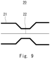
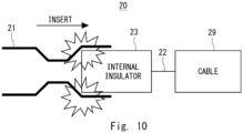
- Figs. 9 and 10 are schematic views illustrating a related relay connector device 20.
- a part of the cross section of a GND shell 21 has a recessed shape.
- the GND shell 21 thereby comes closer to a core wire 22. This allows improving the impedance matching.
- Fig. 10 if the GND shell 21 has a recessed shape, when an internal insulator 23 is inserted into the GND shell 21 for assembly, the internal insulator 23 and the recess of the GND shell 21 come into contact, which makes it difficult to assembly the related relay connector device 20. This hinders the core wire 22 disposed between the internal insulator 23 and a cable 29 from coming closer to the GND shell 21. The improvement of the impedance matching is thereby not achieved in the related relay connector device 20.
- a relay connector device 30 according to the first embodiment is described hereinafter.
- This embodiment does not adopt the approach that brings the GND shell 110 or the like close to the core wires 191 and 291 to reduce the impedance of the core wires 191 and 291 near the spatial layers 195 and 295.
- this embodiment incorporates an impedance adjuster into the internal housings 130 and 230. The impedance of the relay connector device is thereby adjusted.
- Fig. 11 is a sectional view illustrating the relay connector device 30 according to the first embodiment.
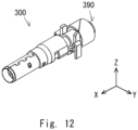
- Fig. 12 is a perspective view illustrating a connector 300 in the relay connector device 30 according to the first embodiment.
- Fig. 13 is a perspective view illustrating a connector 400 in the relay connector device 30 according to the first embodiment.
- an external housing is omitted. Note that the relay connector device 30 may be used in separation from the external housing.
- the relay connector device 30 includes the connector 300 and the connector 400.
- the connector 300 is the connector 300 on the male side
- the connector 400 is the connector 400 on the female side, for example.
- the connector 300 is connected to an end of a cable 390.
- the connector 400 is connected to an end of a cable 490.
- the connector 300 is connected to the connector 400.
- the relay connector device 30 thereby relays the cable 390 and the cable 490.
- Fig. 14 is an exploded perspective view illustrating each member constituting the connector 300 in the relay connector device 30 according to the first embodiment.
- Fig. 15 is a perspective view illustrating an internal housing 330 and an impedance adjuster 360 in the relay connector device 30 according to the first embodiment.
- the internal housing 330 is shown transparent.
- the connector 300 includes a GND shell 310, the internal housing 330, a contact 340, a sleeve 350, the impedance adjuster 360, an EMI shell 370, and an external housing 380.
- the basic structures and functions of the GND shell 310, the internal housing 330, the contact 340, the sleeve 350, and the external housing 380 in the connector 300 are the same as the structures and functions of the GND shells 110 and 120, the internal housing 130, the contact 140, the sleeve 150, and the external housing 180 in the connector 100, respectively.
- the GND shell 310 corresponds to an integrated combination of the GND shells 110 and 120 in the connector 100.
- the internal housing 330, the contact 340, and the impedance adjuster 360 are disposed inside the GND shell 310. Further, the sleeve 350 and a part of the cable 390 are disposed inside the GND shell 310.
- the internal housing 330 may be press-fit to the inside of the GND shell 310.
- An end of the GND shell 310 on the +x axis direction side is disposed in close proximity to an end of the internal housing 330 on the +x axis direction side.
- an end of the GND shell 310 on the -x axis direction side is located above an outside cover 394 of the cable 390.
- the position on the x axis of the end of the GND shell 310 on the -x axis direction side may coincide with that of an end of the sleeve 350 on the -x axis direction side.
- the internal housing 330 incorporates a part of the impedance adjuster 360.
- a part of the internal housing 330 on the - x axis direction side incorporates a part of the impedance adjuster 360 on the +x axis direction side.
- the internal housing 330 is disposed inside the GND shell 310.
- the contact 340 is disposed inside the internal housing 330.
- the internal housing 330 supports the contact 340.
- the internal housing 330 has a recess 331 in its end surface on the +x axis direction side.
- One end of the contact 340 on the +x axis direction side projects from a bottom surface of the recess 331.
- One end of the contact 340 on the +x axis direction side includes a projection 341.
- a side wall of the recess 331 of the internal housing 330 surrounds the projection 341 of the contact 340 on the +x axis direction side.
- An end of the internal housing 330 on the -x axis direction side is disposed in close proximity to an end of the contact 340 on the -x axis direction side.
- the position on the x axis of the end of the internal housing 330 on the -x axis direction side may coincide with that of another end of the contact 340 on the -x axis direction side.
- a core wire 391 of the cable 390 is connected to the end of the contact 340 on the -x axis direction side.
- a connection part between the contact 340 and the core wire 391 may be disposed inside the internal housing 330.
- the contact 340 has the projection 341 at one end on the +x axis direction side.
- One end of the contact 340 on the +x axis direction side is connected to a contact 440 of the connector 400 on the female side.
- the projection 341 of the contact 340 on the +x axis direction side has a projecting shape to mate with the contact 440.
- the other end of the contact 340 on the -x axis direction side is connected to a core wire 391 of the cable 390.
- the sleeve 350 includes a first part 351 in cylindrical shape and a second part 352 in cylindrical shape.
- the first part 351 is disposed inside the GND shell 310.
- the first part 351 covers a shield 393 that is exposed from an end of the outside cover 394 of the cable 390.
- the second part 352 covers the outside cover 394 of the cable 390.
- a connection part between the first part 351 and the second part 352 is thus located in close proximity to an end of the outside cover 394.
- the impedance adjuster 360 has a part incorporated into the internal housing 330.
- a part of the impedance adjuster 360 on the +x axis direction side is incorporated into a part of the internal housing 330 on the -x axis direction side.
- the impedance adjuster 360 may be incorporated into the internal housing 330 by insert molding.
- the impedance adjuster 360 may be incorporated into the internal housing 330 by being press-fit into the internal housing 330.
- the impedance adjuster 360 contains a conductor.
- the impedance adjuster 360 contains a metal as a material.
- the impedance adjuster 360 may contain a material other than a metal as long as it contains a conductor.
- the impedance adjuster 360 may be electrically isolated from the contact 340 and the core wire 391, which are a transmission path of a high-frequency signal, and may be electrically isolated from the ground potential.
- the impedance adjuster 360 may be a hollow ground potential that is not directly connected to another conductor. This eliminates the need for a circuit for connecting the impedance adjuster 360 to another conductor and reduces the impedance near a spatial layer 395 containing air in the relay connector device 30, thereby improving the impedance matching.
- the impedance adjuster 360 may be electrically connected to the ground potential.
- the impedance adjuster 360 may be connected to the GND shell 310 so that the impedance adjuster 360 is held at electrically ground potential. This allows reducing the impedance near the spatial layer 395 containing air in the relay connector device 30, thereby improving the impedance matching.
- the impedance adjuster 360 has a tube shape.
- the impedance adjuster 360 has a cylindrical shape.
- the impedance adjuster 360 is disposed in such a way that its center axis is in the x axis direction.
- the impedance adjuster 360 has a tube shape with its center axis located at the contact 340 and the core wire 391 of the cable 390.
- the impedance adjuster 360 may have a square tube shape or may have a square tube shape whose corners are rounded as long as it has a tube shape. Further, the impedance adjuster 360 may have a tube shape where a plurality of members are combined into tube shape or may have a cut in a part of a tube shape. The impedance adjuster 360 adjusts the impedance by surrounding the contact 340 and the core wire 391 at the center axis, and thereby improves the impedance matching.
- the impedance adjuster 360 is disposed inside the GND shell 310.
- An end of the impedance adjuster 360 on the +x axis direction side is located inside the internal housing 330.
- An end of the impedance adjuster 360 on the -x axis direction side is located above a coating 392 of the cable 390.
- An end of the coating 392 on the +x axis direction side of the cable 390 is a cut surface.
- the impedance adjuster 360 covers the end of the coating 392.
- the impedance adjuster 360 thereby covers an exposed part of the core wire 391.
- the impedance adjuster 360 covers an exposed part of the core wire 391 connected to the contact 340, which is exposed from the internal housing 330.
- the spatial layer 395 is formed between the exposed part of the core wire 391 connected to the contact 340, which is exposed from the internal housing 330, and the GND shell 310.
- the impedance adjuster 360 is disposed in the spatial layer 395 that is formed between the exposed part and the GND shell 310.
- the EMI shell 370 contains a conductor.
- the EMI shell 370 contains a metal as a material.
- the EMI shell 370 may contain a material other than a metal as long as it contains a conductor.
- the EMI shell 370 has a semicylinder shape. The EMI shell 370 comes into contact with the GND shell 310 and covers a part of the GND shell 310. For example, the EMI shell 370 covers an opening of the GND shell 310.
- An assembly of the GND shell 310, the internal housing 330, the contact 340, the sleeve 350, the impedance adjuster 360, and the EMI shell 370 is mounted inside the external housing 380.
- the cable 390 includes the core wire 391, the coating 392, the shield 393, and the outside cover 394.
- the structures and functions of the core wire 391, the coating 392, the shield 393, and the outside cover 394 in the cable 390 are the same as the structures and functions of the core wire 191, the coating 192, the shield 193, and the outside cover 194 in the cable 190, respectively.
- Fig. 16 is an exploded perspective view illustrating each member constituting the connector 400 in the relay connector device 30 according to the first embodiment.
- Fig. 17 is a perspective view illustrating an internal housing 430 and an impedance adjuster 460 in the relay connector device 30 according to the first embodiment.
- the internal housing 430 is shown transparent.
- the connector 400 includes a GND shell 410, an internal housing 430, a contact 440, a sleeve 450, an impedance adjuster 460, an EMI shell 470, and an external housing 480.
- the cable 390 is located on the -x axis direction side of the connector 300
- the cable 490 is located on the +x axis direction side of the connector 400.
- the basic structures and functions of the GND shell 410, the internal housing 430, the contact 440, the sleeve 450, the impedance adjuster 460, the EMI shell 470, and the external housing 480 of the connector 400 are the same as the structures and functions of the GND shell 310, the internal housing 330, the contact 340, the sleeve 350, the impedance adjuster 360, the EMI shell 370, and the external housing 380 of the connector 300, respectively.
- the internal housing 430, the contact 440, and the impedance adjuster 460 are disposed inside the GND shell 410. Further, the sleeve 450 and a part of the cable 490 are disposed inside the GND shell 410.
- the internal housing 430 may be press-fit to the inside of the GND shell 410.
- An end of the GND shell 410 on the -x axis direction side is disposed in close proximity to an end of the internal housing 430 on the -x axis direction side.
- an end of the GND shell 410 on the +x axis direction side is located above an outside cover 494 of the cable 490.
- the position on the x axis of the end of the GND shell 410 on the +x axis direction side may coincide with that of an end of the sleeve 450 on the +x axis direction side.
- a part of the internal housing 430 on the +x axis direction side incorporates a part of the impedance adjuster 460 on the -x axis direction side.
- the internal housing 430 is disposed inside the GND shell 410.
- the contact 440 is disposed inside the internal housing 430.
- the internal housing 430 supports the contact 440.
- the internal housing 430 includes a first part 431 and a second part 432.
- the first part 431 is disposed on the -x axis direction side of the second part 432.
- the first part 431 and the second part 432 have a cylindrical shape whose center axis coincides with the center axis of the internal housing 430.
- the outside diameter of the first part 431 is smaller than the outside diameter of the second part 432.
- the first part 431 mates with the recess 331 of the internal housing 330 of the connector 300. When the first part 431 mates with the recess 331, the projection 341 of the contact 340 of the connector 300 mates with a recess 441 of the contact 440 of the connector 400.
- An end of the internal housing 430 on the -x axis direction side is an end surface of the first part 431 on the -x axis direction side.
- the end of the internal housing 430 on the -x axis direction side is disposed in close proximity to an end of the GND shell 410 on the -x axis direction side.
- the position on the x axis of the end of the internal housing 430 on the -x axis direction side may coincide with that of the end of the GND shell 410 on the -x axis direction side.
- the recess 441 on the -x axis direction side of the contact 440 is disposed inside the first part 431.
- An end of the internal housing 430 on the +x axis direction side is disposed in close proximity to an end of the contact 440 on the +x axis direction side.
- the position on the x axis of the end of the internal housing 430 on the +x axis direction side may coincide with that of another end of the contact 440 on the +x axis direction side.
- a core wire 491 of the cable 490 is connected to the end of the contact 440 on the +x axis direction side.
- a connection part between the contact 440 and the core wire 491 of the cable 490 may be disposed inside the internal housing 430.
- the contact 440 has the recess 441 at one end on the -x axis direction side.
- the contact 440 is disposed inside the internal housing 430.
- An end of the contact 440 on the +x axis direction side is connected to the core wire 491 of the cable 490.
- the projection 341 of the contact 340 in the connector 300 on the male side mates with the recess 441 of the contact 440 in the connector 400 on the female side.
- the sleeve 450 includes a first part 451 in cylindrical shape and a second part 452 in cylindrical shape.
- the first part 451 is disposed on the -x axis direction side of the second part 452.
- the outside diameter of the first part 451 is smaller than the outside diameter of the second part 452.
- the inside diameter of the first part 451 is smaller than the inside diameter of the second part 452.
- the first part 451 is disposed inside the GND shell 410.
- the first part 451 covers a shield 493 that is exposed from an end of the outside cover 494 of the cable 490.
- the second part 452 covers the outside cover 494 of the cable 490.
- a connection part between the first part 451 and the second part 452 is thus located in close proximity to an end of the outside cover 494.
- the impedance adjuster 460 has a part incorporated into the internal housing 430.
- a part of the impedance adjuster 460 on the -x axis direction side is incorporated into a part of the internal housing 430 on the +x axis direction side.
- the impedance adjuster 460 is disposed inside the GND shell 410.
- An end of the impedance adjuster 460 on the -x axis direction side is located inside the internal housing 430.
- An end of the impedance adjuster 460 on the +x axis direction side is located above a coating 492 of the cable 490.
- An end of the coating 492 on the -x axis direction side of the cable 490 is a cut surface.
- the impedance adjuster 460 covers the end of the coating 492.
- the impedance adjuster 460 covers an exposed part of the core wire 491 connected to the contact 440, which is exposed from the internal housing 430.
- a spatial layer 495 is formed between the exposed part of the core wire 491 connected to the contact 440, which is exposed from the internal housing 430, and the GND shell 410.
- the impedance adjuster 460 is disposed in the spatial layer 495 that is formed between the exposed part and the GND shell 410.
- the EMI shell 470 comes into contact with the GND shell 410 and covers a part of the GND shell 410.
- the EMI shell 470 covers an opening of the GND shell 410.
- An assembly of the GND shell 410, the internal housing 430, the contact 440, the sleeve 450, the impedance adjuster 460, and the EMI shell 470 is mounted inside the external housing 480.
- the cable 490 includes the core wire 491, the coating 492, a shield 493, and the outside cover 494.
- the structures and functions of the core wire 491, the coating 492, the shield 493, and the outside cover 494 in the cable 490 are the same as the structures and functions of the core wire 391, the coating 392, the shield 393, and the outside cover 394 in the cable 390, respectively.
- the direction in which the core wire 491 connects to the contact 440, the direction of the end surface of the coating 492 having the cut surface, the direction of the end of the shield 493 and the direction in which it is folded, the direction of the end surface of the outside cover 494 and the like are opposite to those in the cable 390.
- Fig. 18 is a sectional view illustrating the operation of connecting the connectors 300 and 400 in the relay connector device 30 according to the first embodiment.
- the connector 300 and the connector 400 are opposed to each other.
- the projection 341 of the contact 340 mates with the recess 441 of the contact 440.
- a transmission path of a high-frequency signal is thereby formed between the contact 340 and the contact 440.
- the first part 431 of the internal housing 430 may mate with the recess 331 of the internal housing 330.
- the GND shell 310 and the GND shell 410 come into contact with each other.
- a shield that covers the transmission path of a high-frequency signal is thereby formed.
- the impedance adjuster 360 covers to surround the core wire 391 exposed from the internal housing 330 and the coating 392 in the spatial layer 395. Further, the impedance adjuster 460 covers to surround the core wire 491 exposed from the internal housing 430 and the coating 492 in the spatial layer 495.
- the relay connector device 30 includes the impedance adjusters 360 and 460.
- the impedance adjuster 360 covers an exposed part of the core wire 391 connected to the contact 340, which is exposed from the internal housing 330.
- the impedance adjuster 360 allows adjusting the impedance of the relay connector device 30 and thereby improving the impedance matching.
- An advantageous effect of the impedance adjuster 460 is the same as that of the impedance adjuster 360, and the description thereof is omitted hereinbelow.
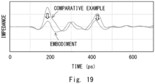
- Fig. 19 is a graph illustrating the impedance in the relay connector device 30 according to the first embodiment, where the horizontal axis indicates time and the vertical axis indicates impedance.
- Fig, 19 also shows the impedance of the relay connector device 10 according to the comparative example. As shown in Fig. 19 , the impedance of the relay connector device 30 according to this embodiment is lower than the impedance of the relay connector device 10 according to the comparative example, thus being improved.
- the impedance adjuster 360 is incorporated into the internal housing 330. This allows fixing the size and shape of the impedance adjuster 360 and thereby improves the stability of the impedance.
- the impedance adjuster 360 in the relay connector device 30 is disposed in the spatial layer 395 that is formed between the exposed part of the core wire 391 and the GND shell 310. This allows controlling an increase in impedance in the core wire 391 of the cable 390 which is exposed in the spatial layer 395 containing air. This further improves the impedance matching.
- the impedance adjuster 360 has a tube shape with its center axis located at the contact 340 and the core wire 391. This allows covering up the contact 340 and the core wire 391 in an isotropic manner and thereby equally adjusting the impedance.
- the impedance adjuster 360 may be incorporated into the internal housing 330 by insert molding. This allows securely fixing the impedance adjuster 360 to the internal housing 330.
- the impedance adjuster 360 may be incorporated into the internal housing 330 by being press-fit into the internal housing 330. This allows easily incorporating the impedance adjuster 360 into the internal housing 330.
Landscapes
- Details Of Connecting Devices For Male And Female Coupling (AREA)
Abstract
| Provided is a coaxial cable connector with improved impedance matching. A relay connector device (30), which is an example of a coaxial cable connector, is a relay connector device including a connector (300) that relays a cable (390). The connector (300) includes a contact (340) containing a conductor, an internal housing (330) containing an insulator and supporting the contact (340), and an impedance adjuster (360) having a part incorporated into the internal housing (330) and containing the conductor. The impedance adjuster (360) covers an exposed part of a core wire (391) of the cable (390) connected to the contact (340), which is exposed from the internal housing (330).
Description
- The present disclosure relates to a coaxial cable connector.
- In an on-vehicle coaxial connector, it is essential to adjust impedance to improve transmission characteristics in terms of performance enhancement. In a relay connector device that relays a cable, it is important to control an increase in impedance of a spatial layer in a crimp part between a contact and a copper wire.
- In a relay connector device as disclosed in
Japanese Unexamined Patent Application Publication No. 2020-107567 - The present disclosure has been accomplished to solve the above problem, and an object of the present disclosure is thus to provide a coaxial cable connector with improved impedance matching.
- According to an aspect of the present disclosure, a coaxial cable connector is a coaxial cable connector including a connector for relaying a cable, the connector including a contact containing a conductor, an insulator body containing an insulator and supporting the contact, and an impedance adjuster having a part incorporated into the insulator body and containing the conductor, wherein the impedance adjuster covers an exposed part of a core wire of the cable connected to the contact, the exposed part being exposed from the insulator body.
- In the above-described coaxial cable connector, the connector may further include a GND shell containing the conductor, the contact, the insulator body, and the impedance adjuster may be disposed inside the GND shell, and the impedance adjuster is disposed in a spatial layer formed between the exposed part and the GND shell.
- In the above-described coaxial cable connector, the impedance adjuster may have a tube shape with a center axis located at the contact and the core wire.
- In the above-described coaxial cable connector, the cable may include the core wire containing the conductor, a coating having a part covering the core wire and containing the insulator, a shield having a part covering the coating and containing the conductor, and an outside cover having a part covering the shield and containing the insulator, and the impedance adjuster may cover an end of the coating.
- In the above-described coaxial cable connector, the impedance adjuster may be incorporated into the insulator body by insert molding.
- In the above-described coaxial cable connector, the impedance adjuster may be incorporated into the insulator body by being press-fit to the insulator body.
- In the above-described coaxial cable connector, the impedance adjuster may be electrically connected to the GND shell.
- In the above-described coaxial cable connector, the impedance adjuster may be electrically isolated from the GND shell, the contact, and the core wire.
- According to an aspect of the present disclosure, a coaxial cable connector is a coaxial cable connector including a first connector and a second connector for relaying a first cable and a second cable, wherein the first connector includes a first contact containing a conductor and including a projection at one end, a first insulator body containing an insulator and supporting the first contact, and a first impedance adjuster having a part incorporated into the first insulator body and containing the conductor, the first impedance adjuster covers an exposed part of a first core wire of the first cable connected to another end of the first contact, the exposed part being exposed from the first insulator body, the second connector includes a second contact containing the conductor and including a recess at one end, a second insulator body containing the insulator and supporting the second contact, and a second impedance adjuster having a part incorporated into the second insulator body and containing the conductor, the second impedance adjuster covers an exposed part of a second core wire of the second cable connected to another end of the second contact, the exposed part being exposed from the second insulator body, and the projection of the first contact mates with the recess of the second contact.
- According to the present disclosure, there is provided a coaxial cable connector with improved impedance matching.
- The above and other objects, features and advantages of the present disclosure will become more fully understood from the detailed description given hereinbelow and the accompanying drawings which are given by way of illustration only, and thus are not to be considered as limiting the present disclosure.
-
-
Fig. 1 is a sectional view illustrating a relay connector device according to a comparative example; -
Fig. 2 is a perspective view illustrating a connector in the relay connector device according to the comparative example; -
Fig. 3 is a perspective view illustrating a connector in the relay connector device according to the comparative example; -
Fig. 4 is an exploded perspective view illustrating each member constituting the connector in the relay connector device according to the comparative example; -
Fig. 5 is a perspective view illustrating an internal housing in the relay connector device according to the comparative example; -
Fig. 6 is an exploded perspective view illustrating each member constituting the connector in the relay connector device according to the comparative example; -
Fig. 7 is a perspective view illustrating an internal housing in the relay connector device according to the comparative example; -
Fig. 8 is a sectional view illustrating the operation of connecting connectors in the relay connector device according to the comparative example; -
Fig. 9 is a schematic view illustrating a related relay connector device; -
Fig. 10 is a schematic view illustrating a related relay connector device; -
Fig. 11 is a sectional view illustrating a relay connector device according to a first embodiment; -
Fig. 12 is a perspective view illustrating a connector in the relay connector device according to the first embodiment; -
Fig. 13 is a perspective view illustrating a connector in the relay connector device according to the first embodiment; -
Fig. 14 is an exploded perspective view illustrating each member constituting the connector in the relay connector device according to the first embodiment; -
Fig. 15 is a perspective view illustrating an internal housing and an impedance adjuster in the relay connector device according to the first embodiment; -
Fig. 16 is an exploded perspective view illustrating each member constituting the connector in the relay connector device according to the first embodiment; -
Fig. 17 is a perspective view illustrating the internal housing and the impedance adjuster in the relay connector device according to the first embodiment; -
Fig. 18 is a sectional view illustrating the operation of connecting connectors in the relay connector device according to the first embodiment; and -
Fig. 19 is a graph illustrating impedance in the relay connector device according to the first embodiment, where the horizontal axis indicates time and the vertical axis indicates impedance. - A specific structure of the present disclosure will be described hereinbelow with reference to the drawings. The description provided hereinbelow merely illustrates a preferred embodiment of the present disclosure, and the present disclosure is not limited to the below-described embodiment. In the following description, the identical reference symbols denote substantially identical elements. For clarity of the drawings, some reference symbols and hatching are omitted.
- A coaxial cable connector according to this embodiment will be described. In the following, a relay connector device that relays a cable will be described as an example of the coaxial cable connector according to this embodiment. Note that the coaxial cable connector according to this embodiment is not limited to the relay connector device, and it may include another connector device such as a coaxial connector device where a cable mates with a board as long as it is configured to connect a coaxial cable. Prior to describing a relay connector device according to a first embodiment, a relay connector device according to a comparative example will be described for comparison. This will clarify the features of the relay connector device according to the first embodiment.
- The relay connector device according to the comparative example is described hereinafter.
Fig. 1 is a sectional view illustrating arelay connector device 10 according to a comparative example.Fig. 2 is a perspective view illustrating aconnector 100 in therelay connector device 10 according to the comparative example.Fig. 3 is a perspective view illustrating aconnector 200 in therelay connector device 10 according to the comparative example. InFigs. 1 to 3 , an external housing is omitted. Note that therelay connector device 10 may be used in separation from the external housing. - As shown in
Figs. 1 to 3 , therelay connector device 10 according to the comparative example includes theconnector 100 and theconnector 200. Theconnector 100 is theconnector 100 on the male side, for example, and theconnector 200 is theconnector 200 on the female side, for example. Theconnector 100 is connected to an end of acable 190. Theconnector 200 is connected to an end of acable 290. Theconnector 100 is connected to theconnector 200. Therelay connector device 10 thereby relays thecable 190 and thecable 290. - For the convenience of description of the
relay connector device 10 and arelay connector device 20, which is described later, the xyz-orthogonal coordinate axis system is used. For example, an axial direction that is coaxial with therelay connector device 10 or the like is referred to as x axis direction. A direction where theconnector 100 on the male side is headed to theconnector 200 on the female side when connecting theconnector 100 and theconnector 200 is referred to as +x direction. Two directions orthogonal to the x axis are referred to as y axis direction and z axis direction. - The
connector 100 on the male side is described hereinafter.Fig. 4 is an exploded perspective view illustrating each member constituting theconnector 100 in therelay connector device 10 according to the comparative example.Fig. 5 is a perspective view illustrating aninternal housing 130 in therelay connector device 10 according to the comparative example. As shown inFigs. 1 to 2 andFigs. 4 to 5 , theconnector 100 includes aGND shell 110, aGND shell 120, aninternal housing 130, acontact 140, asleeve 150, and anexternal housing 180. Each member is described hereinbelow. - The
GND shell 110 and theGND shell 120 contain a conductor as a material. For example, theGND shell 110 and theGND shell 120 contain a metal as a material. Note that theGND shell 110 and theGND shell 120 may contain a material other than a metal as long as it contains a conductor. TheGND shell 110 and theGND shell 120 are electrically connected to a ground potential. - The
GND shell 110 and theGND shell 120 have a tube shape. For example, theGND shell 110 and theGND shell 120 have a cylindrical shape. TheGND shell 110 and theGND shell 120 are disposed in such a way that their center axes are in the x axis direction. The center axes of theGND shell 110 and theGND shell 120 coincide with each other. TheGND shell 110 is disposed on the +x axis direction side of theGND shell 120. TheGND shell 110 may partly overlap theGND shell 120. For example, a part of theGND shell 110 on the -x axis direction side overlaps a part of theGND shell 120 on the +x axis direction side. TheGND shell 110 and theGND shell 120 integrally have a cylindrical shape. - The
internal housing 130 and thecontact 140 are disposed inside theGND shell 110 and theGND shell 120. Thesleeve 150 and a part of thecable 190 may be disposed inside theGND shell 120. Theinternal housing 130 may be press-fit to the inside of theGND shell 110. - An end of the
GND shell 110 on the +x axis direction side is disposed in close proximity to an end of theinternal housing 130 on the +x axis direction side. The position on the x axis of the end of theGND shell 110 on the +x axis direction side may coincide with that of the end of theinternal housing 130 on the +x axis direction side. An end of theGND shell 120 on the -x axis direction side is located above anoutside cover 194 of thecable 190. The end of theGND shell 120 on the -x axis direction side is disposed in close proximity to an end of thesleeve 150 on the -x axis direction side. For example, the position on the x axis of the end of theGND shell 120 on the -x axis direction side may coincide with that of the end of thesleeve 150 on the -x axis direction side. - The
internal housing 130 contains an insulator as a material. Theinternal housing 130 is also called an insulator body. For example, theinternal housing 130 contains a resin as a material. Note that theinternal housing 130 may contain a material other than a resin as long as it contains an insulator. - The
internal housing 130 has a tube shape. For example, theinternal housing 130 has a cylindrical shape. Theinternal housing 130 is disposed in such a way that its center axis is in the x axis direction. Theinternal housing 130 is disposed inside theGND shell 110. Thecontact 140 is disposed inside theinternal housing 130. Thus, theinternal housing 130 supports thecontact 140. Thecontact 140 disposed inside theinternal housing 130 may be press-fit into theinternal housing 130. - The
internal housing 130 has arecess 131 in its end surface on the +x axis direction side. An end of thecontact 140 on the +x axis direction side projects from a bottom surface of therecess 131. One end of thecontact 140 on the +x axis direction side includes aprojection 141. A side wall of therecess 131 of theinternal housing 130 surrounds the end of thecontact 140 on the +x axis direction side. - An end of the
internal housing 130 on the -x axis direction side is located in close proximity to an end of thecontact 140 on the -x axis direction side. For example, the position on the x axis of the end of theinternal housing 130 on the -x axis direction side may coincide with that of another end of thecontact 140 on the -x axis direction side. Acore wire 191 of thecable 190 is connected to the end of thecontact 140 on the -x axis direction side. A connection part between thecontact 140 and thecore wire 191 of thecable 190 may be disposed inside theinternal housing 130. - The
contact 140 contains a conductor as a material. For example, thecontact 140 contains a metal as a material. Note that thecontact 140 may contain a material other than a metal as long as it contains a conductor. Thecontact 140 serves as a transmission path of a high-frequency signal, for example. - The
contact 140 has a bar shape. Thecontact 140 is disposed in such a way that its center axis is in the x axis direction. Thecontact 140 has theprojection 141 at one end on the +x axis direction side. Thecontact 140 is disposed inside theinternal housing 130. The other end of thecontact 140 on the -x axis direction side is connected to thecore wire 191 of thecable 190. Theprojection 141 at one end of thecontact 140 on the +x axis direction side is connected to acontact 240 of theconnector 200 on the female side. Theprojection 141 of thecontact 140 has a projecting shape to mate with arecess 241 of thecontact 240. - The
sleeve 150 contains a conductor as a material. For example, thesleeve 150 contains a metal as a material. Note that thesleeve 150 may contain a material other than a metal as long as it contains a conductor. - The
sleeve 150 has a tube shape. For example, thesleeve 150 has a cylindrical shape. Thesleeve 150 is disposed in such a way that its center axis is in the x axis direction. Thesleeve 150 includes afirst part 151 in cylindrical shape and asecond part 152 in cylindrical shape. Thefirst part 151 and thesecond part 152 are connected in parallel in the x axis direction. Thefirst part 151 is disposed on the +x axis direction side of thesecond part 152. The outside diameter of thefirst part 151 is smaller than the outside diameter of thesecond part 152. The inside diameter of thefirst part 151 is smaller than the inside diameter of thesecond part 152. - The
first part 151 is disposed inside theGND shell 120. Thefirst part 151 covers ashield 193 that is exposed from an end of theoutside cover 194 of thecable 190. Thesecond part 152 covers theoutside cover 194 of thecable 190. A connection part between thefirst part 151 and thesecond part 152 is located in close proximity to an end of theoutside cover 194 on the +x axis direction side. - The
external housing 180 contains an insulator as a material. For example, theexternal housing 180 contains a resin as a material. Note that theexternal housing 180 may contain a material other than a resin as long as it contains an insulator. - The
external housing 180 has a tube shape. For example, theexternal housing 180 has a square tube shape. Theexternal housing 180 is disposed in such a way that its center axis is in the x axis direction. An assembly of theGND shell 110, theGND shell 120, theinternal housing 130, thecontact 140, and thesleeve 150 is mounted inside theexternal housing 180. - The structure of the
cable 190 is described hereinafter. Thecable 190 extends in one direction and has flexibility. Thecable 190 includes thecore wire 191, acoating 192, ashield 193, and theoutside cover 194. Thecore wire 191, thecoating 192, theshield 193, and theoutside cover 194 are disposed in concentric layers. Those members are stacked concentrically with thecore wire 191 at the center. When thecable 190 extends in the x axis direction, those members are stacked concentrically with their center axes in the x axis direction. Thecoating 192 covers a side surface of thecore wire 191. Theshield 193 covers a side surface of thecoating 192. Theoutside cover 194 covers a side surface of theshield 193. - The
core wire 191 contains a conductor as a material. Thecore wire 191 has a linear shape. Thecore wire 191 may contain a copper wire, for example. Note that thecore wire 191 may contain a material other than a copper wire as long as it contains a linear conductor. A part of thecore wire 191 on the +x axis direction side projects from an end of thecoating 192 on the +x axis direction side. - The
coating 192 contains an insulator as a material. For example, thecoating 192 contains a resin as a material. Note that thecoating 192 may contain a material other than a resin as long as it contains an insulator. Thecoating 192 has a tube shape. Thecoating 192 has a part that covers the side surface of thecore wire 191. The end of thecoating 192 on the +x axis direction side may be a cut surface. A part of thecoating 192 on the +x axis direction side may be exposed from an end of theshield 193 on the +x axis direction side. - The
shield 193 contains a conductor as a material. For example, theshield 193 may contain a metal. Note that theshield 193 may contain a material other than a metal as long as it contains a conductor. Theshield 193 has a tube shape. Theshield 193 has a part that covers the side surface of thecoating 192. The end of theshield 193 on the +x axis direction side is folded to the -x axis direction side. To be specific, the end of theshield 193 on the +x axis direction side is folded to the -x axis direction side along an edge of thefirst part 151 of thesleeve 150 on the +x axis direction side. The end of the foldedshield 193 on the +x axis direction side is connected to an inner surface of theGND shell 120. Thus, theshield 193 is electrically connected to the ground potential. A part of theshield 193 on the +x axis direction side may be exposed from an end of theoutside cover 194 on the +x axis direction side. - The
outside cover 194 contains an insulator as a material. For example, theoutside cover 194 may contain a resin. Theoutside cover 194 may contain a material other than a resin as long as it contains an insulator. Theoutside cover 194 has a tube shape. Theoutside cover 194 has a part that covers the side surface of theshield 193. The end of theoutside cover 194 on the +x axis direction side may be a cut surface. A part of theoutside cover 194 on the +x axis direction side may be covered with at least any one of thesleeve 150 and theGND shell 120. - The
connector 200 on the female side is described hereinafter.Fig. 6 is an exploded perspective view illustrating each member constituting theconnector 200 in therelay connector device 10 according to the comparative example.Fig. 7 is a perspective view illustrating aninternal housing 230 in therelay connector device 10 according to the comparative example. As shown inFig. 1 ,Fig. 3 , andFigs. 6 to 7 , theconnector 200 includes aGND shell 210, aGND shell 220, aninternal housing 230, acontact 240, asleeve 250, and anexternal housing 280. - In the case of the
connector 100, thecable 190 is located on the -x axis direction side of theconnector 100, whereas in the case of theconnector 200, thecable 290 is located on the +x axis direction side of theconnector 200. Otherwise, the basic structures and functions of theGND shell 210, theGND shell 220, theinternal housing 230, thecontact 240, thesleeve 250, and theexternal housing 280 of theconnector 200 are the same as the structures and functions of theGND shell 110, theGND shell 120, theinternal housing 130, thecontact 140, thesleeve 150, and theexternal housing 180 of theconnector 100, respectively. - The
GND shell 210 is disposed on the -x axis direction side of theGND shell 220. Theinternal housing 230 and thecontact 240 are disposed inside theGND shell 210 and theGND shell 220. Thesleeve 250 and thecable 290 may be disposed inside theGND shell 220. Theinternal housing 230 may be press-fit to the inside of theGND shell 210. - An end of the
GND shell 210 on the -x axis direction side is disposed in close proximity to an end of theinternal housing 230 on the -x axis direction side. The position on the x axis of the end of theGND shell 210 on the -x axis direction side may coincide with that of the end of theinternal housing 230 on the -x axis direction side. An end of theGND shell 220 on the +x axis direction side is located above anoutside cover 294 of thecable 290. The end of theGND shell 220 on the +x axis direction side is disposed in close proximity to an end of thesleeve 250 on the +x axis direction side. For example, the position on the x axis of the end of theGND shell 220 on the +x axis direction side may coincide with that of the end of thesleeve 250 on the +x axis direction side. - The
internal housing 230 is disposed inside theGND shell 210. Thecontact 240 is disposed inside theinternal housing 230. Thus, thecontact 240 is disposed inside theGND shell 210. Theinternal housing 230 supports thecontact 240. - The
internal housing 230 includes afirst part 231 and asecond part 232. Thefirst part 231 is disposed on the -x axis direction side of thesecond part 232. Thefirst part 231 and thesecond part 232 have a cylindrical shape whose center axis coincides with the center axis of theinternal housing 230. The outside diameter of thefirst part 231 is smaller than the outside diameter of thesecond part 232. Thefirst part 231 mates with therecess 131 of theinternal housing 130 of theconnector 100. When thefirst part 231 mates with therecess 131, theprojection 141 of thecontact 140 of theconnector 100 mates with therecess 241 of thecontact 240 of theconnector 200. - An end of the
internal housing 230 on the -x axis direction side is an end surface of thefirst part 231 on the -x axis direction side. The end of theinternal housing 230 on the -x axis direction side is disposed in close proximity to an end of theGND shell 210 on the -x axis direction side. For example, the position on the x axis of the end of theinternal housing 230 on the -x axis direction side may coincide with that of the end of theGND shell 210 on the -x axis direction side. Therecess 241 on the -x axis direction side of thecontact 240 is disposed inside thefirst part 231. - An end of the
internal housing 230 on the +x axis direction side is disposed in close proximity to an end of thecontact 240 on the +x axis direction side. For example, the position on the x axis of the end of theinternal housing 230 on the +x axis direction side may coincide with that of another end of thecontact 240 on the +x axis direction side. Acore wire 291 of thecable 290 is connected to the end of thecontact 240 on the +x axis direction side. A connection part between thecontact 240 and thecore wire 291 of thecable 290 may be disposed inside theinternal housing 230. - The
contact 240 has therecess 241 at one end on the -x axis direction side. Thecontact 240 is disposed inside theinternal housing 230. An end of thecontact 240 on the +x axis direction side is connected to thecore wire 291 of thecable 290. Theprojection 141 of thecontact 140 mates with therecess 241 of thecontact 240. - The
sleeve 250 includes afirst part 251 in cylindrical shape and asecond part 252 in cylindrical shape. Thefirst part 251 is disposed on the -x axis direction side of thesecond part 252. The outside diameter of thefirst part 251 is smaller than the outside diameter of thesecond part 252. The inside diameter of thefirst part 251 is smaller than the inside diameter of thesecond part 252. - The
first part 251 is disposed inside theGND shell 220. Thefirst part 251 covers ashield 293 that is exposed from an end of theoutside cover 294 of thecable 290. Thesecond part 252 covers theoutside cover 294 of thecable 290. A connection part between thefirst part 251 and thesecond part 252 is thus located in close proximity to an end of theoutside cover 294. - The
cable 290 includes thecore wire 291, acoating 292, theshield 293, and theoutside cover 294. The structures and functions of thecore wire 291, thecoating 292, theshield 293, and theoutside cover 294 in thecable 290 are the same as the structures and functions of thecore wire 191, thecoating 192, theshield 193, and theoutside cover 194 in thecable 190, respectively. Note that, however, the direction in which thecore wire 291 connects to thecontact 240, the direction of the end surface of thecoating 292 having the cut surface, the direction of the end of theshield 293 and the direction in which it is folded, the direction of the end surface of theoutside cover 294 and the like are opposite to those in thecable 190. - The operation of connection of the
relay connector device 10 according to the comparative example is described hereinafter.Fig. 8 is a sectional view illustrating the operation of connecting theconnectors Figs. 1 and8 , in therelay connector device 10 according to the comparative example, theconnector 100 and theconnector 200 are opposed to each other. Then, theprojection 141 of thecontact 140 mates with therecess 241 of thecontact 240. A transmission path of a high-frequency signal is thereby formed between thecontact 140 and thecontact 240. At the same time, thefirst part 231 of theinternal housing 230 may mate with therecess 131 of theinternal housing 130. Further, theGND shell 110 and theGND shell 210 come into contact with each other. A shield that covers the transmission path of a high-frequency signal is thereby formed. - In the
relay connector device 10, aspatial layer 195 is formed between thecore wire 191 and theGND shells contact 140 on the -x axis direction side and the end of thecore wire 191 on the +x axis direction side to the end of thecoating 192 of thecable 190 on the +x axis direction side. To be specific, thespatial layer 195 is formed between an exposed part of thecore wire 191 connected to thecontact 140, which is exposed from theinternal housing 130 and thecoating 192, and theGND shells - Further, a
spatial layer 295 is formed between thecore wire 291 and theGND shells contact 240 on the +x axis direction side and the end of thecore wire 291 on the -x axis direction side to the end of thecoating 292 of thecable 290 on the -x axis direction side. To be specific, thespatial layer 295 is formed between an exposed part of thecore wire 291 connected to thecontact 240, which is exposed from theinternal housing 230 and thecoating 292, and theGND shells - As described above, the
spatial layers contacts spatial layers relay connector device 10 increases. This makes it difficult to improve the matching with design impedance. One approach to reduce the impedance near thespatial layers GND shells core wires -
Figs. 9 and10 are schematic views illustrating a relatedrelay connector device 20. As shown inFig. 9 , in the relatedrelay connector device 20, a part of the cross section of aGND shell 21 has a recessed shape. TheGND shell 21 thereby comes closer to acore wire 22. This allows improving the impedance matching. However, as shown inFig. 10 , if theGND shell 21 has a recessed shape, when aninternal insulator 23 is inserted into theGND shell 21 for assembly, theinternal insulator 23 and the recess of theGND shell 21 come into contact, which makes it difficult to assembly the relatedrelay connector device 20. This hinders thecore wire 22 disposed between theinternal insulator 23 and acable 29 from coming closer to theGND shell 21. The improvement of the impedance matching is thereby not achieved in the relatedrelay connector device 20. - A
relay connector device 30 according to the first embodiment is described hereinafter. This embodiment does not adopt the approach that brings theGND shell 110 or the like close to thecore wires core wires spatial layers internal housings -
Fig. 11 is a sectional view illustrating therelay connector device 30 according to the first embodiment.Fig. 12 is a perspective view illustrating aconnector 300 in therelay connector device 30 according to the first embodiment.Fig. 13 is a perspective view illustrating aconnector 400 in therelay connector device 30 according to the first embodiment. InFigs. 11 to 13 , an external housing is omitted. Note that therelay connector device 30 may be used in separation from the external housing. - As shown in
Figs. 11 to 13 , therelay connector device 30 according to this embodiment includes theconnector 300 and theconnector 400. Theconnector 300 is theconnector 300 on the male side, and theconnector 400 is theconnector 400 on the female side, for example. Theconnector 300 is connected to an end of acable 390. Theconnector 400 is connected to an end of acable 490. Theconnector 300 is connected to theconnector 400. Therelay connector device 30 thereby relays thecable 390 and thecable 490. -
Fig. 14 is an exploded perspective view illustrating each member constituting theconnector 300 in therelay connector device 30 according to the first embodiment.Fig. 15 is a perspective view illustrating aninternal housing 330 and animpedance adjuster 360 in therelay connector device 30 according to the first embodiment. InFig. 15 , theinternal housing 330 is shown transparent. As shown inFigs. 11 to 12 andFigs. 14 to 15 , theconnector 300 includes aGND shell 310, theinternal housing 330, acontact 340, asleeve 350, theimpedance adjuster 360, anEMI shell 370, and anexternal housing 380. The basic structures and functions of theGND shell 310, theinternal housing 330, thecontact 340, thesleeve 350, and theexternal housing 380 in theconnector 300 are the same as the structures and functions of theGND shells internal housing 130, thecontact 140, thesleeve 150, and theexternal housing 180 in theconnector 100, respectively. - The
GND shell 310 corresponds to an integrated combination of theGND shells connector 100. Theinternal housing 330, thecontact 340, and theimpedance adjuster 360 are disposed inside theGND shell 310. Further, thesleeve 350 and a part of thecable 390 are disposed inside theGND shell 310. Theinternal housing 330 may be press-fit to the inside of theGND shell 310. - An end of the
GND shell 310 on the +x axis direction side is disposed in close proximity to an end of theinternal housing 330 on the +x axis direction side. On the other hand, an end of theGND shell 310 on the -x axis direction side is located above anoutside cover 394 of thecable 390. The position on the x axis of the end of theGND shell 310 on the -x axis direction side may coincide with that of an end of thesleeve 350 on the -x axis direction side. - As shown in
Fig. 15 , theinternal housing 330 incorporates a part of theimpedance adjuster 360. For example, a part of theinternal housing 330 on the - x axis direction side incorporates a part of theimpedance adjuster 360 on the +x axis direction side. - The
internal housing 330 is disposed inside theGND shell 310. Thecontact 340 is disposed inside theinternal housing 330. Theinternal housing 330 supports thecontact 340. Theinternal housing 330 has arecess 331 in its end surface on the +x axis direction side. One end of thecontact 340 on the +x axis direction side projects from a bottom surface of therecess 331. One end of thecontact 340 on the +x axis direction side includes aprojection 341. A side wall of therecess 331 of theinternal housing 330 surrounds theprojection 341 of thecontact 340 on the +x axis direction side. - An end of the
internal housing 330 on the -x axis direction side is disposed in close proximity to an end of thecontact 340 on the -x axis direction side. The position on the x axis of the end of theinternal housing 330 on the -x axis direction side may coincide with that of another end of thecontact 340 on the -x axis direction side. Acore wire 391 of thecable 390 is connected to the end of thecontact 340 on the -x axis direction side. A connection part between thecontact 340 and thecore wire 391 may be disposed inside theinternal housing 330. - The
contact 340 has theprojection 341 at one end on the +x axis direction side. One end of thecontact 340 on the +x axis direction side is connected to acontact 440 of theconnector 400 on the female side. Theprojection 341 of thecontact 340 on the +x axis direction side has a projecting shape to mate with thecontact 440. The other end of thecontact 340 on the -x axis direction side is connected to acore wire 391 of thecable 390. - The
sleeve 350 includes afirst part 351 in cylindrical shape and asecond part 352 in cylindrical shape. Thefirst part 351 is disposed inside theGND shell 310. Thefirst part 351 covers ashield 393 that is exposed from an end of theoutside cover 394 of thecable 390. Thesecond part 352 covers theoutside cover 394 of thecable 390. A connection part between thefirst part 351 and thesecond part 352 is thus located in close proximity to an end of theoutside cover 394. - As shown in
Fig. 15 , theimpedance adjuster 360 has a part incorporated into theinternal housing 330. To be specific, for example, a part of theimpedance adjuster 360 on the +x axis direction side is incorporated into a part of theinternal housing 330 on the -x axis direction side. Theimpedance adjuster 360 may be incorporated into theinternal housing 330 by insert molding. Alternatively, theimpedance adjuster 360 may be incorporated into theinternal housing 330 by being press-fit into theinternal housing 330. - The
impedance adjuster 360 contains a conductor. For example, theimpedance adjuster 360 contains a metal as a material. Note that theimpedance adjuster 360 may contain a material other than a metal as long as it contains a conductor. Theimpedance adjuster 360 may be electrically isolated from thecontact 340 and thecore wire 391, which are a transmission path of a high-frequency signal, and may be electrically isolated from the ground potential. In other words, theimpedance adjuster 360 may be a hollow ground potential that is not directly connected to another conductor. This eliminates the need for a circuit for connecting theimpedance adjuster 360 to another conductor and reduces the impedance near aspatial layer 395 containing air in therelay connector device 30, thereby improving the impedance matching. - Note that the
impedance adjuster 360 may be electrically connected to the ground potential. For example, theimpedance adjuster 360 may be connected to theGND shell 310 so that theimpedance adjuster 360 is held at electrically ground potential. This allows reducing the impedance near thespatial layer 395 containing air in therelay connector device 30, thereby improving the impedance matching. - The
impedance adjuster 360 has a tube shape. For example, theimpedance adjuster 360 has a cylindrical shape. Theimpedance adjuster 360 is disposed in such a way that its center axis is in the x axis direction. Thus, theimpedance adjuster 360 has a tube shape with its center axis located at thecontact 340 and thecore wire 391 of thecable 390. - Note that the
impedance adjuster 360 may have a square tube shape or may have a square tube shape whose corners are rounded as long as it has a tube shape. Further, theimpedance adjuster 360 may have a tube shape where a plurality of members are combined into tube shape or may have a cut in a part of a tube shape. Theimpedance adjuster 360 adjusts the impedance by surrounding thecontact 340 and thecore wire 391 at the center axis, and thereby improves the impedance matching. - The
impedance adjuster 360, together with theinternal housing 330 and thecontact 340, is disposed inside theGND shell 310. An end of theimpedance adjuster 360 on the +x axis direction side is located inside theinternal housing 330. An end of theimpedance adjuster 360 on the -x axis direction side is located above acoating 392 of thecable 390. An end of thecoating 392 on the +x axis direction side of thecable 390 is a cut surface. Thus, theimpedance adjuster 360 covers the end of thecoating 392. Theimpedance adjuster 360 thereby covers an exposed part of thecore wire 391. - As described above, the
impedance adjuster 360 covers an exposed part of thecore wire 391 connected to thecontact 340, which is exposed from theinternal housing 330. Thespatial layer 395 is formed between the exposed part of thecore wire 391 connected to thecontact 340, which is exposed from theinternal housing 330, and theGND shell 310. Theimpedance adjuster 360 is disposed in thespatial layer 395 that is formed between the exposed part and theGND shell 310. - The
EMI shell 370 contains a conductor. For example, theEMI shell 370 contains a metal as a material. Note that theEMI shell 370 may contain a material other than a metal as long as it contains a conductor. TheEMI shell 370 has a semicylinder shape. TheEMI shell 370 comes into contact with theGND shell 310 and covers a part of theGND shell 310. For example, theEMI shell 370 covers an opening of theGND shell 310. - An assembly of the
GND shell 310, theinternal housing 330, thecontact 340, thesleeve 350, theimpedance adjuster 360, and theEMI shell 370 is mounted inside theexternal housing 380. - The
cable 390 includes thecore wire 391, thecoating 392, theshield 393, and theoutside cover 394. The structures and functions of thecore wire 391, thecoating 392, theshield 393, and theoutside cover 394 in thecable 390 are the same as the structures and functions of thecore wire 191, thecoating 192, theshield 193, and theoutside cover 194 in thecable 190, respectively. - The
connector 400 on the female side is described hereinafter.Fig. 16 is an exploded perspective view illustrating each member constituting theconnector 400 in therelay connector device 30 according to the first embodiment.Fig. 17 is a perspective view illustrating aninternal housing 430 and animpedance adjuster 460 in therelay connector device 30 according to the first embodiment. InFig. 17 , theinternal housing 430 is shown transparent. As shown inFig. 11 ,Fig. 13 , andFigs. 16 to 17 , theconnector 400 includes aGND shell 410, aninternal housing 430, acontact 440, asleeve 450, animpedance adjuster 460, anEMI shell 470, and anexternal housing 480. - In the case of the
connector 300, thecable 390 is located on the -x axis direction side of theconnector 300, whereas in the case of theconnector 400, thecable 490 is located on the +x axis direction side of theconnector 400. Otherwise, the basic structures and functions of theGND shell 410, theinternal housing 430, thecontact 440, thesleeve 450, theimpedance adjuster 460, theEMI shell 470, and theexternal housing 480 of theconnector 400 are the same as the structures and functions of theGND shell 310, theinternal housing 330, thecontact 340, thesleeve 350, theimpedance adjuster 360, theEMI shell 370, and theexternal housing 380 of theconnector 300, respectively. - The
internal housing 430, thecontact 440, and theimpedance adjuster 460 are disposed inside theGND shell 410. Further, thesleeve 450 and a part of thecable 490 are disposed inside theGND shell 410. Theinternal housing 430 may be press-fit to the inside of theGND shell 410. - An end of the
GND shell 410 on the -x axis direction side is disposed in close proximity to an end of theinternal housing 430 on the -x axis direction side. On the other hand, an end of theGND shell 410 on the +x axis direction side is located above anoutside cover 494 of thecable 490. The position on the x axis of the end of theGND shell 410 on the +x axis direction side may coincide with that of an end of thesleeve 450 on the +x axis direction side. - As shown in
Fig. 17 , a part of theinternal housing 430 on the +x axis direction side incorporates a part of theimpedance adjuster 460 on the -x axis direction side. Theinternal housing 430 is disposed inside theGND shell 410. Thecontact 440 is disposed inside theinternal housing 430. Thus, theinternal housing 430 supports thecontact 440. - The
internal housing 430 includes afirst part 431 and asecond part 432. Thefirst part 431 is disposed on the -x axis direction side of thesecond part 432. Thefirst part 431 and thesecond part 432 have a cylindrical shape whose center axis coincides with the center axis of theinternal housing 430. The outside diameter of thefirst part 431 is smaller than the outside diameter of thesecond part 432. Thefirst part 431 mates with therecess 331 of theinternal housing 330 of theconnector 300. When thefirst part 431 mates with therecess 331, theprojection 341 of thecontact 340 of theconnector 300 mates with arecess 441 of thecontact 440 of theconnector 400. - An end of the
internal housing 430 on the -x axis direction side is an end surface of thefirst part 431 on the -x axis direction side. The end of theinternal housing 430 on the -x axis direction side is disposed in close proximity to an end of theGND shell 410 on the -x axis direction side. For example, the position on the x axis of the end of theinternal housing 430 on the -x axis direction side may coincide with that of the end of theGND shell 410 on the -x axis direction side. Therecess 441 on the -x axis direction side of thecontact 440 is disposed inside thefirst part 431. - An end of the
internal housing 430 on the +x axis direction side is disposed in close proximity to an end of thecontact 440 on the +x axis direction side. For example, the position on the x axis of the end of theinternal housing 430 on the +x axis direction side may coincide with that of another end of thecontact 440 on the +x axis direction side. Acore wire 491 of thecable 490 is connected to the end of thecontact 440 on the +x axis direction side. A connection part between thecontact 440 and thecore wire 491 of thecable 490 may be disposed inside theinternal housing 430. - The
contact 440 has therecess 441 at one end on the -x axis direction side. Thecontact 440 is disposed inside theinternal housing 430. An end of thecontact 440 on the +x axis direction side is connected to thecore wire 491 of thecable 490. Theprojection 341 of thecontact 340 in theconnector 300 on the male side mates with therecess 441 of thecontact 440 in theconnector 400 on the female side. - The
sleeve 450 includes afirst part 451 in cylindrical shape and asecond part 452 in cylindrical shape. Thefirst part 451 is disposed on the -x axis direction side of thesecond part 452. The outside diameter of thefirst part 451 is smaller than the outside diameter of thesecond part 452. The inside diameter of thefirst part 451 is smaller than the inside diameter of thesecond part 452. - The
first part 451 is disposed inside theGND shell 410. Thefirst part 451 covers ashield 493 that is exposed from an end of theoutside cover 494 of thecable 490. Thesecond part 452 covers theoutside cover 494 of thecable 490. A connection part between thefirst part 451 and thesecond part 452 is thus located in close proximity to an end of theoutside cover 494. - As shown in
Fig. 17 , theimpedance adjuster 460 has a part incorporated into theinternal housing 430. To be specific, for example, a part of theimpedance adjuster 460 on the -x axis direction side is incorporated into a part of theinternal housing 430 on the +x axis direction side. - The
impedance adjuster 460, together with theinternal housing 430 and thecontact 440, is disposed inside theGND shell 410. An end of theimpedance adjuster 460 on the -x axis direction side is located inside theinternal housing 430. An end of theimpedance adjuster 460 on the +x axis direction side is located above acoating 492 of thecable 490. An end of thecoating 492 on the -x axis direction side of thecable 490 is a cut surface. Thus, theimpedance adjuster 460 covers the end of thecoating 492. - The
impedance adjuster 460 covers an exposed part of thecore wire 491 connected to thecontact 440, which is exposed from theinternal housing 430. Aspatial layer 495 is formed between the exposed part of thecore wire 491 connected to thecontact 440, which is exposed from theinternal housing 430, and theGND shell 410. Theimpedance adjuster 460 is disposed in thespatial layer 495 that is formed between the exposed part and theGND shell 410. - The
EMI shell 470 comes into contact with theGND shell 410 and covers a part of theGND shell 410. For example, theEMI shell 470 covers an opening of theGND shell 410. - An assembly of the
GND shell 410, theinternal housing 430, thecontact 440, thesleeve 450, theimpedance adjuster 460, and theEMI shell 470 is mounted inside theexternal housing 480. - The
cable 490 includes thecore wire 491, thecoating 492, ashield 493, and theoutside cover 494. The structures and functions of thecore wire 491, thecoating 492, theshield 493, and theoutside cover 494 in thecable 490 are the same as the structures and functions of thecore wire 391, thecoating 392, theshield 393, and theoutside cover 394 in thecable 390, respectively. Note that, however, the direction in which thecore wire 491 connects to thecontact 440, the direction of the end surface of thecoating 492 having the cut surface, the direction of the end of theshield 493 and the direction in which it is folded, the direction of the end surface of theoutside cover 494 and the like are opposite to those in thecable 390. - The operation of connection of the
relay connector device 30 according to this embodiment is described hereinafter.Fig. 18 is a sectional view illustrating the operation of connecting theconnectors relay connector device 30 according to the first embodiment. As shown inFigs. 11 and18 , in therelay connector device 30 according to this embodiment, theconnector 300 and theconnector 400 are opposed to each other. Then, theprojection 341 of thecontact 340 mates with therecess 441 of thecontact 440. A transmission path of a high-frequency signal is thereby formed between thecontact 340 and thecontact 440. At the same time, thefirst part 431 of theinternal housing 430 may mate with therecess 331 of theinternal housing 330. Further, theGND shell 310 and theGND shell 410 come into contact with each other. A shield that covers the transmission path of a high-frequency signal is thereby formed. - The
impedance adjuster 360 covers to surround thecore wire 391 exposed from theinternal housing 330 and thecoating 392 in thespatial layer 395. Further, theimpedance adjuster 460 covers to surround thecore wire 491 exposed from theinternal housing 430 and thecoating 492 in thespatial layer 495. - An advantageous effect of this embodiment is described hereinafter. The
relay connector device 30 according to this embodiment includes theimpedance adjusters impedance adjuster 360 covers an exposed part of thecore wire 391 connected to thecontact 340, which is exposed from theinternal housing 330. Thus, theimpedance adjuster 360 allows adjusting the impedance of therelay connector device 30 and thereby improving the impedance matching. An advantageous effect of theimpedance adjuster 460 is the same as that of theimpedance adjuster 360, and the description thereof is omitted hereinbelow. -
Fig. 19 is a graph illustrating the impedance in therelay connector device 30 according to the first embodiment, where the horizontal axis indicates time and the vertical axis indicates impedance.Fig, 19 also shows the impedance of therelay connector device 10 according to the comparative example. As shown inFig. 19 , the impedance of therelay connector device 30 according to this embodiment is lower than the impedance of therelay connector device 10 according to the comparative example, thus being improved. - Further, the
impedance adjuster 360 is incorporated into theinternal housing 330. This allows fixing the size and shape of theimpedance adjuster 360 and thereby improves the stability of the impedance. - Further, the
impedance adjuster 360 in therelay connector device 30 according to this embodiment is disposed in thespatial layer 395 that is formed between the exposed part of thecore wire 391 and theGND shell 310. This allows controlling an increase in impedance in thecore wire 391 of thecable 390 which is exposed in thespatial layer 395 containing air. This further improves the impedance matching. - The
impedance adjuster 360 has a tube shape with its center axis located at thecontact 340 and thecore wire 391. This allows covering up thecontact 340 and thecore wire 391 in an isotropic manner and thereby equally adjusting the impedance. - The
impedance adjuster 360 may be incorporated into theinternal housing 330 by insert molding. This allows securely fixing theimpedance adjuster 360 to theinternal housing 330. On the other hand, theimpedance adjuster 360 may be incorporated into theinternal housing 330 by being press-fit into theinternal housing 330. This allows easily incorporating theimpedance adjuster 360 into theinternal housing 330. - Although an embodiment of the present disclosure is described in the foregoing, the present disclosure involves appropriate modifications without impairment of its object and effects and is not restricted to the above-described embodiment. Further, the structures in the comparative example and the first embodiment may be appropriately combined.
- From the disclosure thus described, it will be obvious that the embodiments of the disclosure may be varied in many ways. Such variations are not to be regarded as a departure from the spirit and scope of the disclosure, and all such modifications as would be obvious to one skilled in the art are intended for inclusion within the scope of the following claims.
Claims (9)
- A coaxial cable connector comprising a connector for relaying a cable, the connector comprising:a contact containing a conductor;an insulator body containing an insulator and supporting the contact; andan impedance adjuster having a part incorporated into the insulator body and containing the conductor,wherein the impedance adjuster covers an exposed part of a core wire of the cable connected to the contact, the exposed part being exposed from the insulator body.
- The coaxial cable connector according to claim 1, whereinthe connector further comprises a GND shell containing the conductor,the contact, the insulator body, and the impedance adjuster are disposed inside the GND shell, andthe impedance adjuster is disposed in a spatial layer formed between the exposed part and the GND shell.
- The coaxial cable connector according to claim 2, wherein the impedance adjuster has a tube shape with a center axis located at the contact and the core wire.
- The coaxial cable connector according to claim 3, wherein
the cable includes:the core wire containing the conductor;a coating having a part covering the core wire and containing the insulator;a shield having a part covering the coating and containing the conductor; andan outside cover having a part covering the shield and containing the insulator,wherein the impedance adjuster covers an end of the coating. - The coaxial cable connector according to claim 1, wherein the impedance adjuster is incorporated into the insulator body by insert molding.
- The coaxial cable connector according to claim 1, wherein the impedance adjuster is incorporated into the insulator body by being press-fit to the insulator body.
- The coaxial cable connector according to claim 2, wherein the impedance adjuster is electrically connected to the GND shell.
- The coaxial cable connector according to claim 2, wherein the impedance adjuster is electrically isolated from the GND shell, the contact, and the core wire.
- A coaxial cable connector comprising a first connector and a second connector for relaying a first cable and a second cable, whereinthe first connector comprises:a first contact containing a conductor and including a projection at one end;a first insulator body containing an insulator and supporting the first contact; anda first impedance adjuster having a part incorporated into the first insulator body and containing the conductor,the first impedance adjuster covers an exposed part of a first core wire of the first cable connected to another end of the first contact, the exposed part being exposed from the first insulator body,the second connector comprises:a second contact containing the conductor and including a recess at one end;a second insulator body containing the insulator and supporting the second contact; anda second impedance adjuster having a part incorporated into the second insulator body and containing the conductor,the second impedance adjuster covers an exposed part of a second core wire of the second cable connected to another end of the second contact, the exposed part being exposed from the second insulator body, andthe projection of the first contact mates with the recess of the second contact.
Applications Claiming Priority (1)
| Application Number | Priority Date | Filing Date | Title |
|---|---|---|---|
| JP2023129028A JP2025024774A (en) | 2023-08-08 | 2023-08-08 | Coaxial Cable Connectors |
Publications (1)
| Publication Number | Publication Date |
|---|---|
| EP4507137A1 true EP4507137A1 (en) | 2025-02-12 |
Family
ID=92214327
Family Applications (1)
| Application Number | Title | Priority Date | Filing Date |
|---|---|---|---|
| EP24192956.1A Pending EP4507137A1 (en) | 2023-08-08 | 2024-08-05 | Coaxial cable connector |
Country Status (5)
| Country | Link |
|---|---|
| US (1) | US20250055238A1 (en) |
| EP (1) | EP4507137A1 (en) |
| JP (1) | JP2025024774A (en) |
| KR (1) | KR102949711B1 (en) |
| CN (1) | CN119481848A (en) |
Citations (5)
| Publication number | Priority date | Publication date | Assignee | Title |
|---|---|---|---|---|
| JP2001283999A (en) * | 2000-04-03 | 2001-10-12 | Auto Network Gijutsu Kenkyusho:Kk | Cable connector and its impedance adjustment method |
| JP2011009111A (en) * | 2009-06-26 | 2011-01-13 | Yazaki Corp | Connector for coaxial cable |
| JP2020107567A (en) | 2018-12-28 | 2020-07-09 | 株式会社オートネットワーク技術研究所 | Wire with terminal, terminal module and connector |
| US20220231462A1 (en) * | 2019-06-13 | 2022-07-21 | Autonetworks Technologies, Ltd. | Connector |
| JP2023013512A (en) * | 2021-07-16 | 2023-01-26 | 矢崎総業株式会社 | shield connector |
-
2023
- 2023-08-08 JP JP2023129028A patent/JP2025024774A/en active Pending
-
2024
- 2024-07-24 KR KR1020240097672A patent/KR102949711B1/en active Active
- 2024-07-25 CN CN202411002086.1A patent/CN119481848A/en active Pending
- 2024-08-05 EP EP24192956.1A patent/EP4507137A1/en active Pending
- 2024-08-07 US US18/796,907 patent/US20250055238A1/en active Pending
Patent Citations (5)
| Publication number | Priority date | Publication date | Assignee | Title |
|---|---|---|---|---|
| JP2001283999A (en) * | 2000-04-03 | 2001-10-12 | Auto Network Gijutsu Kenkyusho:Kk | Cable connector and its impedance adjustment method |
| JP2011009111A (en) * | 2009-06-26 | 2011-01-13 | Yazaki Corp | Connector for coaxial cable |
| JP2020107567A (en) | 2018-12-28 | 2020-07-09 | 株式会社オートネットワーク技術研究所 | Wire with terminal, terminal module and connector |
| US20220231462A1 (en) * | 2019-06-13 | 2022-07-21 | Autonetworks Technologies, Ltd. | Connector |
| JP2023013512A (en) * | 2021-07-16 | 2023-01-26 | 矢崎総業株式会社 | shield connector |
Also Published As
| Publication number | Publication date |
|---|---|
| KR102949711B1 (en) | 2026-04-08 |
| CN119481848A (en) | 2025-02-18 |
| JP2025024774A (en) | 2025-02-21 |
| US20250055238A1 (en) | 2025-02-13 |
| KR20250022613A (en) | 2025-02-17 |
Similar Documents
| Publication | Publication Date | Title |
|---|---|---|
| US10763600B2 (en) | Connector structure | |
| US11955751B2 (en) | Connector | |
| US10027073B2 (en) | Coaxial connector with electromagnetic shield | |
| US9028278B2 (en) | Shield connector | |
| EP2178177B1 (en) | Shield connector | |
| US7785118B2 (en) | Coaxial cable connector having a compensating tab | |
| US20140099822A1 (en) | Header assembly | |
| JP4729307B2 (en) | Circuit board connector having an integral dielectric cover | |
| CN113196583B (en) | Terminal-equipped wire, terminal module, and connector | |
| JP2023018175A (en) | connector | |
| US20220302656A1 (en) | Connector and connector device | |
| US20250055238A1 (en) | Coaxial cable connector | |
| US11165187B2 (en) | Connector | |
| EP4525213A1 (en) | Coaxial connector device | |
| CN112636091B (en) | Coaxial connector | |
| US20230155332A1 (en) | Electrical connector | |
| US12283782B2 (en) | Electronic component | |
| JPH05347162A (en) | Insulation electric terminal and its manufacture | |
| CN222483762U (en) | Cable Connectors | |
| EP4478547B1 (en) | Connector and cable connector comprising connector and cable | |
| JP2003308913A (en) | Female terminal fitting | |
| US12586960B2 (en) | Terminal unit, and connector including the same | |
| US20240356278A1 (en) | Connector with a Dielectric Secured in a Housing | |
| JP7019477B2 (en) | High frequency module | |
| CN115693302A (en) | Shielded connector |
Legal Events
| Date | Code | Title | Description |
|---|---|---|---|
| PUAI | Public reference made under article 153(3) epc to a published international application that has entered the european phase |
Free format text: ORIGINAL CODE: 0009012 |
|
| STAA | Information on the status of an ep patent application or granted ep patent |
Free format text: STATUS: EXAMINATION IS IN PROGRESS |
|
| 17P | Request for examination filed |
Effective date: 20240805 |
|
| AK | Designated contracting states |
Kind code of ref document: A1 Designated state(s): AL AT BE BG CH CY CZ DE DK EE ES FI FR GB GR HR HU IE IS IT LI LT LU LV MC ME MK MT NL NO PL PT RO RS SE SI SK SM TR |