CN113196583B - Terminal-equipped wire, terminal module, and connector - Google Patents
Terminal-equipped wire, terminal module, and connector Download PDFInfo
- Publication number
- CN113196583B CN113196583B CN201980081659.5A CN201980081659A CN113196583B CN 113196583 B CN113196583 B CN 113196583B CN 201980081659 A CN201980081659 A CN 201980081659A CN 113196583 B CN113196583 B CN 113196583B
- Authority
- CN
- China
- Prior art keywords
- terminal
- wire
- covered
- exposed
- adjusting member
- Prior art date
- Legal status (The legal status is an assumption and is not a legal conclusion. Google has not performed a legal analysis and makes no representation as to the accuracy of the status listed.)
- Active
Links
Images


Classifications
-
- H—ELECTRICITY
- H01—ELECTRIC ELEMENTS
- H01R—ELECTRICALLY-CONDUCTIVE CONNECTIONS; STRUCTURAL ASSOCIATIONS OF A PLURALITY OF MUTUALLY-INSULATED ELECTRICAL CONNECTING ELEMENTS; COUPLING DEVICES; CURRENT COLLECTORS
- H01R13/00—Details of coupling devices of the kinds covered by groups H01R12/70 or H01R24/00 - H01R33/00
- H01R13/648—Protective earth or shield arrangements on coupling devices, e.g. anti-static shielding
- H01R13/658—High frequency shielding arrangements, e.g. against EMI [Electro-Magnetic Interference] or EMP [Electro-Magnetic Pulse]
- H01R13/6591—Specific features or arrangements of connection of shield to conductive members
- H01R13/6592—Specific features or arrangements of connection of shield to conductive members the conductive member being a shielded cable
-
- H—ELECTRICITY
- H01—ELECTRIC ELEMENTS
- H01R—ELECTRICALLY-CONDUCTIVE CONNECTIONS; STRUCTURAL ASSOCIATIONS OF A PLURALITY OF MUTUALLY-INSULATED ELECTRICAL CONNECTING ELEMENTS; COUPLING DEVICES; CURRENT COLLECTORS
- H01R13/00—Details of coupling devices of the kinds covered by groups H01R12/70 or H01R24/00 - H01R33/00
- H01R13/648—Protective earth or shield arrangements on coupling devices, e.g. anti-static shielding
- H01R13/658—High frequency shielding arrangements, e.g. against EMI [Electro-Magnetic Interference] or EMP [Electro-Magnetic Pulse]
- H01R13/6591—Specific features or arrangements of connection of shield to conductive members
- H01R13/65912—Specific features or arrangements of connection of shield to conductive members for shielded multiconductor cable
-
- H—ELECTRICITY
- H01—ELECTRIC ELEMENTS
- H01B—CABLES; CONDUCTORS; INSULATORS; SELECTION OF MATERIALS FOR THEIR CONDUCTIVE, INSULATING OR DIELECTRIC PROPERTIES
- H01B7/00—Insulated conductors or cables characterised by their form
- H01B7/17—Protection against damage caused by external factors, e.g. sheaths or armouring
- H01B7/28—Protection against damage caused by moisture, corrosion, chemical attack or weather
-
- H—ELECTRICITY
- H01—ELECTRIC ELEMENTS
- H01R—ELECTRICALLY-CONDUCTIVE CONNECTIONS; STRUCTURAL ASSOCIATIONS OF A PLURALITY OF MUTUALLY-INSULATED ELECTRICAL CONNECTING ELEMENTS; COUPLING DEVICES; CURRENT COLLECTORS
- H01R13/00—Details of coupling devices of the kinds covered by groups H01R12/70 or H01R24/00 - H01R33/00
- H01R13/646—Details of coupling devices of the kinds covered by groups H01R12/70 or H01R24/00 - H01R33/00 specially adapted for high-frequency, e.g. structures providing an impedance match or phase match
- H01R13/6473—Impedance matching
-
- H—ELECTRICITY
- H01—ELECTRIC ELEMENTS
- H01R—ELECTRICALLY-CONDUCTIVE CONNECTIONS; STRUCTURAL ASSOCIATIONS OF A PLURALITY OF MUTUALLY-INSULATED ELECTRICAL CONNECTING ELEMENTS; COUPLING DEVICES; CURRENT COLLECTORS
- H01R24/00—Two-part coupling devices, or either of their cooperating parts, characterised by their overall structure
-
- H—ELECTRICITY
- H01—ELECTRIC ELEMENTS
- H01R—ELECTRICALLY-CONDUCTIVE CONNECTIONS; STRUCTURAL ASSOCIATIONS OF A PLURALITY OF MUTUALLY-INSULATED ELECTRICAL CONNECTING ELEMENTS; COUPLING DEVICES; CURRENT COLLECTORS
- H01R4/00—Electrically-conductive connections between two or more conductive members in direct contact, i.e. touching one another; Means for effecting or maintaining such contact; Electrically-conductive connections having two or more spaced connecting locations for conductors and using contact members penetrating insulation
- H01R4/10—Electrically-conductive connections between two or more conductive members in direct contact, i.e. touching one another; Means for effecting or maintaining such contact; Electrically-conductive connections having two or more spaced connecting locations for conductors and using contact members penetrating insulation effected solely by twisting, wrapping, bending, crimping, or other permanent deformation
- H01R4/18—Electrically-conductive connections between two or more conductive members in direct contact, i.e. touching one another; Means for effecting or maintaining such contact; Electrically-conductive connections having two or more spaced connecting locations for conductors and using contact members penetrating insulation effected solely by twisting, wrapping, bending, crimping, or other permanent deformation by crimping
- H01R4/183—Electrically-conductive connections between two or more conductive members in direct contact, i.e. touching one another; Means for effecting or maintaining such contact; Electrically-conductive connections having two or more spaced connecting locations for conductors and using contact members penetrating insulation effected solely by twisting, wrapping, bending, crimping, or other permanent deformation by crimping for cylindrical elongated bodies, e.g. cables having circular cross-section
- H01R4/184—Electrically-conductive connections between two or more conductive members in direct contact, i.e. touching one another; Means for effecting or maintaining such contact; Electrically-conductive connections having two or more spaced connecting locations for conductors and using contact members penetrating insulation effected solely by twisting, wrapping, bending, crimping, or other permanent deformation by crimping for cylindrical elongated bodies, e.g. cables having circular cross-section comprising a U-shaped wire-receiving portion
Abstract
The terminal-equipped wire (25) disclosed in the present specification is configured to be provided with a shield wire (11) and an inner conductor (20), wherein the shield wire (11) has at least one covered wire (12) that is formed by covering a core wire (13) for transmitting communication signals with an insulating coating (14), a conductive shield portion (15) that covers the outer periphery of the covered wire (12), and a sheath portion (16) that covers the outer periphery of the shield portion (15), and the inner conductor (20) is connected to the covered wire (12), and wherein the end portion on the inner conductor (20) side of the covered wire (12) is an exposed portion (17) that is exposed from the sheath portion (16) and the shield portion (15), and the exposed portion (17) is covered with an impedance adjusting member (80) that has conductivity.
Description
Technical Field
The technology disclosed by the specification relates to a terminal-equipped wire, a terminal module, and a connector.
Background
For example, as a shield connector connected to a terminal of a shield electric wire, a connector described in japanese patent application laid-open No. 2013-229255 (patent document 1 below) is known. The shield wire is formed by further covering the outer circumferences of a plurality of shield wires, each of which is formed by covering the inner conductor with an insulating protective coating, with a shield foil and a sheath portion, and a male terminal is electrically connected to the end of the inner conductor of each of the shield wires.
Prior art literature
Patent literature
Patent document 1: japanese patent laid-open No. 2013-229255
Disclosure of Invention
Problems to be solved by the invention
However, like this connector, the electrical connection terminal needs to peel off the shield foil and the sheath portion at the end of the shield wire. In this way, a portion not covered with the shielding foil is generated at the end of the shielded wire, and the impedance changes with respect to the portion covered with the shielding foil. At the point of change in impedance, there is a concern that reflection of a signal occurs and communication quality is degraded.
In the present specification, a technique for suppressing degradation of communication quality is disclosed.
Means for solving the problems
The technology disclosed in the present specification is a terminal-equipped wire including a shielded wire having at least one covered wire covered with an insulating coating for transmitting a communication signal, a conductive shield portion covering an outer periphery of the covered wire, and a sheath portion covering an outer periphery of the shield portion, and a terminal connected to the covered wire, wherein an end portion of the covered wire on the terminal side is an exposed portion exposed from the sheath portion and the shield portion, and the exposed portion is covered with an impedance adjusting member having conductivity.
According to the terminal-equipped wire having such a configuration, the exposed portion of the covered wire is covered with the impedance adjusting member having conductivity, and the covered wire exposed from the shield portion is covered with the member having conductivity until the position immediately before connection with the terminal, so that it is possible to suppress a change in impedance between the exposed portion and the covered wire covered with the shield portion in the shielded wire. This can suppress degradation of communication quality in the covered electric wire.
The terminal-equipped wire disclosed in the present specification may be configured as follows.
The shield wire may include a plurality of covered wires, and the impedance adjusting member may include a plurality of tubular adjusting portion bodies mounted along outer peripheral surfaces of the exposed portions, respectively.
According to this configuration, since the adjustment unit body individually covers the exposed portions of the plurality of covered wires exposed from the shielding portion, the change in impedance of the exposed portions can be suppressed by the adjustment unit body individually, and thus, for example, the change in impedance at the exposed portions can be suppressed more than in the case where the exposed portions of the plurality of covered wires are collectively covered with the impedance adjusting member.
The adjustment portion body may have a slit extending in a circumferential direction.
According to this configuration, the area of the adjustment portion main body covering the exposed portion can be easily changed by changing the size of the slit. Thus, the impedance at the exposed portion can be easily adjusted, and the accuracy of adjusting the impedance at the exposed portion can be improved. Therefore, the occurrence of reflection of signals between the exposed portion and the covered wire covered with the shielding portion in the shielded wire can be further suppressed, and the degradation of communication quality can be further suppressed.
The impedance adjusting member may further include a connecting portion for connecting the plurality of adjusting portion bodies.
Since the plurality of adjustment section bodies are connected by the connecting section, the number of parts of the impedance adjusting member can be reduced as compared with a case where the adjustment section bodies are individually configured for each exposed section.
The technology disclosed in the present specification is a terminal module including the terminal-equipped wire and a terminal housing member that houses a plurality of the terminals in parallel, wherein the connecting portion connects the adjustment portion main body such that a distance between the plurality of covered wires is substantially the same as a distance between the terminals housed in the terminal housing member. The term "substantially the same" as used herein is intended to include a case where the distance between covered wires is the same as the distance between terminals, and also includes a case where the distance between covered wires and the distance between terminals are substantially the same even if the distance between the covered wires and the distance between the terminals are slightly different from each other.
According to the terminal module having such a configuration, the distance between the plurality of covered wires can be made equal to the distance between the terminals in the terminal housing member by the connecting portion of the impedance adjusting member, so that the workability of assembling the terminals to the terminal housing member can be improved as compared with, for example, a case where the plurality of terminals are positioned and assembled at the respective assembling positions of the terminal housing member.
The terminal housing member may have an adjustment member housing portion that houses the impedance adjustment member, and a misalignment detecting portion that interferes with the impedance adjustment member when the impedance adjustment member is not mounted at a correct position with respect to the exposed portion may be provided between a portion of the terminal housing member that houses the terminal and the adjustment member housing portion.
For example, when the impedance adjusting member is attached to the exposed portion of the covered wire at a position different from the correct position, the impedance cannot be sufficiently adjusted at the exposed portion, and the communication quality may be degraded. In addition, when the impedance adjusting member is attached so as to be offset toward the terminal, there is a possibility that the terminal contacts the impedance adjusting member and a short circuit may occur between the terminals.
However, according to such a configuration, when the impedance adjusting member is attached to the exposed portion at an incorrect position displaced toward the terminal side, the impedance adjusting member interferes with the displacement detecting portion when the impedance adjusting member is assembled into the adjusting member housing portion, and the impedance adjusting portion cannot be housed in the adjusting member housing portion. This can prevent the communication quality from being degraded by the misalignment of the impedance adjusting member, and can prevent the occurrence of a short circuit between the terminals. In addition, misalignment of the impedance adjusting member from the exposed portion due to vibration or the like can be prevented.
The misalignment detecting section may be a partition wall that separates the plurality of terminals in the terminal housing member.
According to this configuration, the partition wall between the cavities in the terminal housing member can be made to be a misalignment detecting section that detects misalignment of the impedance adjusting member. That is, since it is not necessary to separately form the misalignment detecting portion in the terminal housing member, the shape of the terminal housing member can be suppressed from being complicated.
The technology disclosed by the specification comprises: the terminal module; an outer conductor covering an outer periphery of the terminal module; and a housing that accommodates the terminal module covered with the outer conductor.
Effects of the invention
According to the technology disclosed in the present specification, degradation of communication quality is suppressed.
Drawings
Fig. 1 is a perspective view of a connector according to an embodiment.
Fig. 2 is a front view of the connector.
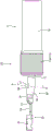
Fig. 3 is a cross-sectional view taken along line A-A of fig. 2.
Fig. 4 is an exploded perspective view of the connector.
Fig. 5 is a perspective view showing a state of the expansion impedance adjusting member.
Fig. 6 is a front view showing a state of the expansion impedance adjusting member.
Fig. 7 is a plan view showing a state in which the impedance adjusting member is unfolded.
Fig. 8 is a bottom view of the upper component.
Fig. 9 is a plan view showing a state in which the inner conductor is connected to the covered wire of the shielded wire.
Fig. 10 is a perspective view showing a state before the impedance adjusting member is attached to the exposed portion.
Fig. 11 is a plan view showing a state in which an exposed portion is arranged at the bottom of the impedance adjusting member.
Fig. 12 is a perspective view of a terminal-equipped wire.
Fig. 13 is a plan view of the terminated wire.
Fig. 14 is a side view of a terminated wire.
Fig. 15 is a sectional view taken along line B-B of fig. 14.
Fig. 16 is a perspective view showing a state before the terminal-equipped wire is assembled to the upper member which is turned upside down.
Fig. 17 is a plan view showing a state in which the upper member turned upside down is assembled with the terminal-equipped wire.
Fig. 18 is a cross-sectional view taken along line C-C of fig. 17.
Fig. 19 is a perspective view showing a state before the upper member is turned upside down to assemble the lower member.
Fig. 20 is a perspective view of the terminal module in a vertically flipped state.
Fig. 21 is a front view of the terminal module.
Fig. 22 is a sectional view taken along line D-D of fig. 21.
Fig. 23 is a cross-sectional view corresponding to fig. 18 showing a state in which the impedance adjusting member mounted at an incorrect position is in contact with the center misalignment detecting section of the terminal housing member.
Fig. 24 is a perspective view of a terminal-equipped wire according to another embodiment.
Detailed Description
Embodiment
An embodiment of the technology disclosed in the present specification will be described with reference to fig. 1 to 23.
The present embodiment exemplifies a connector 10 for communication that is mounted on a vehicle such as an electric vehicle or a hybrid vehicle, and that is disposed, for example, between an in-vehicle electrical component (car navigation system, ETC, monitor, etc.) in the vehicle and an external device (camera, etc.), and on a wired communication path between the in-vehicle electrical components.
As shown in fig. 1 to 4, the connector 10 includes a shielded wire 11, a plurality of inner conductors (an example of a "terminal") 20 connected to the distal end of the front side of the shielded wire 11, a terminal housing member 30 housing the plurality of inner conductors 20, an outer conductor 50 connected to the shielded wire 11 in a state of covering the outer periphery of the terminal housing member 30, and a housing 70 housing the outer conductor 50.
The shielded wire 11 includes a plurality of covered wires 12, a shield portion 15 made of braided wire and covering the outer circumference of the plurality of covered wires 12, and a sheath portion 16 made of insulating coating and covering the outer circumference of the shield portion 15. In the shielded electric wire 11 of the present embodiment, two covered electric wires 12 are covered by the shielding portion 15 at the same time.
Each covered wire 12 is formed in such a manner that a conductive core wire 13 is covered with an insulating cover 14 having insulation properties. The covered electric wires 12 are twisted with the two covered electric wires 12 covered with the shield part 15, and the sheath part 16 is peeled off at the distal end, i.e., the tip part of the shield electric wire 11, exposing the two covered electric wires 12 and the shield part 15 in a state where the twist is untwisted.
The distal end portion of each covered wire 12 exposed from the distal end of the sheath portion 16 is further peeled to expose the core wire 13, and the inner conductor 20 is electrically connected to the exposed core wire 13.
The shielding portion 15 is formed by braiding a plurality of conductive thin metal wires into a tubular shape. The shielding portion 15 exposed from the distal end of the sheath portion 16 is folded back onto the end of the sheath portion 16 to form a folded back portion 15A covering the outer periphery of the distal end of the sheath portion 16.
The inner conductor 20 is formed by processing a metal plate material having conductivity by pressing or the like. The inner conductor 20 is a so-called female terminal, and has a square tubular connection tube portion 22 into which a pin-type male terminal, not shown, is inserted and connected, and an electric wire connection portion 24 that is pressure-bonded to the core wire 13 is continuously formed behind the connection tube portion 22.
As shown in fig. 20, the terminal housing member 30 is made of synthetic resin and formed in a rectangular parallelepiped shape long in the front-rear direction.
As shown in fig. 3 and 22, cavities 31 extending in the front-rear direction are formed in parallel in the left-right direction at the front portion of the terminal housing member 30, which is closer to the front-rear direction center portion. Each cavity 31 is formed to accommodate an inner conductor 20 connected to the covered wire 12.
The rear portion of the terminal housing member 30 is formed to collectively house the large housing portions 32 of the covered wires 12 pulled out rearward from the respective cavities 31.
As shown in fig. 19 and 20, the terminal housing member 30 is configured by combining a lower member 33 disposed at a lower portion and an upper member 40 disposed at an upper portion in a vertical direction.
As shown in fig. 4 and 4, the lower member 33 includes a bottom wall 33D constituting the lower wall 30D of the terminal housing member 30, and a pair of locking pieces 34 provided on both side edges of the bottom wall 33D. The bottom wall 33D is formed in a substantially rectangular plate shape long in the front-rear direction, and two inner conductors 20 are placed side by side in the left-right direction on the bottom wall 33D.
The pair of locking pieces 34 are formed to extend upward from the rear end portion of the bottom wall 33D, and each locking piece 34 has a substantially rectangular locking hole 34A penetrating in the left-right direction.
As shown in fig. 4, 8 and 16, the upper member 40 is configured to include a top wall 40U constituting the upper wall 30U of the terminal housing member 30, a front wall 42 provided at a front end portion of the top wall 40U, and side walls 44 provided at both side edges in the left-right direction of the top wall 40U, respectively.
The top wall 40U is formed in a substantially rectangular flat plate shape that is long in the front-rear direction. A partition wall 45 extending downward from the top wall 40U is formed at a substantially central portion of the top wall 40U in the left-right direction. When the upper member 40 and the lower member 33 are assembled, the partition wall 45 is disposed in close proximity to the bottom wall 33D of the lower member 33 in the vertical direction, and separates the two inner conductors 20 accommodated in the terminal accommodating member 30.
The front wall 42 is formed in a plate shape extending downward from the front end edge of the top wall 40U. The front wall 42 is provided with an insertion port 42A into which a male terminal is inserted.
The pair of side walls 44 are formed to extend downward from the top wall 40U, and are formed continuously at the side edges of the front wall 42 on both sides in the left-right direction.
A fitting recess 44A for fitting the locking piece 34 of the lower member 33 when the upper member 40 and the lower member 33 are assembled is formed at a substantially central portion in the front-rear direction of each side wall 44. The fitting recess 44A is formed so as to be cut from the lower end portion of the side wall 44 to the top wall 40U in the up-down direction, and an engagement projection 46 protruding outward is formed on a side edge of the top wall 40U facing the fitting recess 44A.
As shown in fig. 22, when the upper member 40 and the lower member 33 are assembled and the locking piece 34 of the lower member 33 is fitted into the fitting recess 44A, the locking projection 46 is fitted into the locking hole 34A of the locking piece 34, and the upper member 40 and the lower member 33 are held in the assembled state.
As shown in fig. 3 and 4, the outer conductor 50 is composed of a first outer conductor 51 covering the outer periphery of the terminal housing member 30, and a second outer conductor 60 assembled to the first outer conductor 51 so as to cover the outer periphery of the first outer conductor 51 and the folded-back portion 15A of the shield electric wire 11.
The first outer conductor 51 is formed by processing a conductive metal plate material by pressing or the like, and includes a cylindrical portion 52 that accommodates the terminal accommodating member 30, and a shield connection portion 53 provided at a rear end edge of the cylindrical portion 52.
The cylindrical portion 52 is formed in a square cylindrical shape having a substantially rectangular front view, and the terminal housing member 30 is inserted from the rear of the cylindrical portion 52 and housed in the cylindrical portion 52.
As shown in fig. 3, the shield connection portion 53 includes a tab 54 extending obliquely downward and rearward from the lower rear end edge of the cylindrical portion 52, and a tongue piece 55 extending straight rearward from the rear end edge of the tab 54.
The tongue piece 55 is formed in a substantially rectangular plate shape, and is disposed along the outer peripheral surface of the lower side of the folded-back portion 15A in the shielded wire 11 when the terminal housing member 30 is housed in the cylindrical portion 52.
As shown in fig. 3 and 4, the second outer conductor 60 is formed by processing a conductive metal plate material by pressing or the like, and is configured to include a top plate 61 extending from the cylindrical portion 52 to a position of the folded-back portion 15A of the shield electric wire 11, a pair of fixing sleeves 62 provided at a front portion of the top plate 61, and a pair of connecting sleeves 63 provided at a rear portion of the top plate 61.
The top plate 61 is formed to have a size covering a region from the upper side to the folded portion 15A from the rear of the cylindrical portion 52, and a lance hole 61A penetrating in the vertical direction is provided in the front of the top plate 61.
The pair of fixing sleeves 62 are provided on both lateral edges of the front portion of the top plate 61, and are crimped to the rear portion of the tubular portion 52 so as to be wound from both lateral sides.
The pair of connecting sleeves 63 are provided on both lateral edges of the rear portion of the top plate 61 so as to be connected to the rear of the pair of fixing sleeves 62, and are crimped to the folded-back portion 15A in a winding manner from both lateral sides.
One of the pair of connection sleeves 63 has a side plate 64 disposed along one side portion of the folded-back portion 15A in the left-right direction and a fixing piece 65 provided at an upper end of the side plate 64, and the other connection sleeve 63 has a side plate 64 disposed along the other side portion of the folded-back portion 15A in the left-right direction and two fixing pieces 65 provided at an upper end of the side plate 64.
Each fixing piece 65 is crimped to the folded-back portion 15A in a wound manner together with the tongue piece 55 disposed on the upper surface of the folded-back portion 15A. A hook 66 folded back toward the inside is formed at the front end of each fixing piece 65.
The hook 66 is engaged with one of the lateral side edges of the tongue piece 55 when the fixing pieces 65 are pressed together, and thereby fixes the fixing pieces 65 so as not to come out of the shielding portion 15. Thus, as shown in fig. 3, the outer conductor 50 composed of the first outer conductor 51 and the second outer conductor 60 is fixed to the shield portion 15 of the shielded electric wire 11 in an electrically connected manner.
The housing 70 is made of synthetic resin, and has an outer conductor housing portion 72 that houses the outer conductor 50 connected to the shielded wire 11.
The outer conductor housing portion 72 is formed in a square tubular shape penetrating in the front-rear direction, and a lance 73 that can be engaged with an edge portion of the lance hole 61A of the outer conductor 50 is provided in the outer conductor housing portion 72. The lance 73 is fitted into the lance hole 61A when the outer conductor 50 is accommodated in the correct accommodating position of the outer conductor accommodating portion 72, and the outer conductor 50 is held in the housing 70 by the lance 73 engaging with the edge portion of the lance hole 61A.
As described above, as shown in fig. 12 to 20, the portions of the two covered wires 12 pulled out rearward from the cavities 31 of the terminal housing members 30 are exposed portions 17 exposed from the distal ends of the sheath portions 16 of the shielded wires 11, and the impedance adjusting members 80 are attached to these exposed portions 17.
The impedance adjusting member 80 is formed by processing a conductive metal plate material by pressing or the like. The impedance adjusting member 80 includes a plurality of adjusting section bodies 82 attached to the outer periphery of the exposed section 17 of the covered wire 12, and a connecting section 85 connecting the plurality of adjusting section bodies 82. The impedance adjusting member 80 according to the present embodiment is configured by connecting two adjusting portion bodies 82 attached to two exposed portions 17 of two covered wires 12, respectively, by one connecting portion 85.
Each adjustment portion main body 82 is formed in a substantially cylindrical shape along the outer peripheral surface so as to cover approximately 3/4 of the outer peripheral surface of the exposed portion 17 in the circumferential direction. Each adjustment portion main body 82 has a side opening 83 that opens in the radial direction, and a slit 84 that extends in the circumferential direction is formed in a substantially central portion in the front-rear direction of the edge portion of the side opening 83.
The adjustment portion main body 82 is attached to a substantially central portion of the exposure portion 17 in the front-rear direction, and the length dimension of the adjustment portion main body 82 in the front-rear direction is slightly shorter than the length dimension of the exposure portion 17 in the front-rear direction.
Accordingly, the exposed portions 17 are slightly exposed from both ends of the adjustment portion main body 82 in the front-rear direction for each adjustment portion main body 82. The adjustment unit body 82 is in a state in which the exposure portion 17 is exposed by about 1/4 in the circumferential direction from a side opening 83 provided in the radial direction of the adjustment unit body 82.
The coupling portion 85 couples the two adjustment portion bodies 82 in the left-right direction such that the side openings 83 in the respective adjustment portion bodies 82 face each other in the left-right direction, and the coupling portion 85 is formed in a curved shape so as to bulge upward.
As shown in fig. 13, the connecting portion 85 is formed to have a front portion wider than a rear portion in the lateral direction, and as shown in fig. 16 and 17, the connecting portion 85 is formed to have a distance between the front end portions of the adjustment portion main body 82 connected to the front end portions of the connecting portion 85 and a distance between the inner conductors 20 in the terminal housing member 30 are substantially the same size.
In other words, the connecting portion 85 connects the two adjustment portion bodies 82 such that the distance between the two covered wires 12 each having the adjustment portion body 82 mounted thereon is substantially the same as the distance between the inner conductors 20 housed in the terminal housing member 30. Further, "substantially the same" as described herein is meant to include a case where the distance between the covered wires 12 is the same as the distance between the inner conductors 20, and also includes a case where the distance between the covered wires 12 and the distance between the inner conductors 20 can be regarded as practically the same even if they are not the same.
On the other hand, as shown in fig. 17, the large housing portion 32 of the terminal housing member 30 is formed so that the impedance adjusting member 80 can be housed together with the exposed portions 17 of the two covered wires 12, and the region in which the impedance adjusting member 80 is housed in the front end portion of the large housing portion 32 is formed so as to be wider than the region in which the two cavities 31 are formed in the left-right direction.
A main body position detecting portion (an example of a "misalignment detecting portion") 47 protruding toward the region where the covered wire 12 is disposed is formed on the side wall 30A on both sides in the left-right direction between the region where the cavity 31 is formed and the region where the large housing portion 32 is formed of the terminal housing member 30. The body position detecting portion 47 is disposed in front of the adjusting portion body 82 in a state where the impedance adjusting member 80 attached to the exposing portion 17 is accommodated in the large accommodating portion 32.
The rear end portion of the partition wall 45 that separates the two inner conductors 20 housed in the terminal housing member 30 is formed as a center position detection portion (an "example of a misalignment detection portion") 48 that is disposed in front of the connection portion 85 in a state where the impedance adjusting member 80 mounted on the exposed portion 17 is housed in the large housing portion 32.
As shown in fig. 17 to 19, when the impedance adjusting member 80 is mounted at a correct mounting position with respect to the exposed portion 17, the main body position detecting portion 47 and the center position detecting portion 48 allow the impedance adjusting member 80 to be accommodated in the large accommodating portion 32. On the other hand, as shown in fig. 23, when the impedance adjusting member 80 is mounted at an incorrect mounting position displaced toward the front side with respect to the exposed portion 17, the body position detecting portion 47 is in contact with the adjusting portion body 82 to cause interference, or the center position detecting portion 48 is in contact with the connecting portion 85 to cause interference, so that the impedance adjusting member 80 cannot be accommodated in the terminal accommodating member 30.
The present embodiment is structured as described above, and an example of the mounting step of the connector 10 for communication will be briefly described, and the operation and effects of the connector 10 will be described.
First, the sheath portion 16 of the shielded electric wire 11 is peeled off, the ends of the two covered electric wires 12 and the shielding portion 15 are exposed, and the shielding portion 15 is folded back toward the outer surface of the sheath portion 16 to form a folded back portion 15A. Then, the insulation covers 14 at the distal ends of the two covered wires 12 are peeled off to expose the core wires 13, and as shown in fig. 9, the wire connection portions 24 are crimped to the exposed core wires 13 to connect the inner conductors 20.
Next, the impedance adjusting member 80 is attached to the exposed portions 17 of the two covered wires 12 of the shielded wire 11.
As shown in fig. 5 to 7, in the developed state before being attached to the exposed portion 17, the impedance adjusting member 80 includes a connecting portion 85, two bottom portions 82A connected to side edges of the connecting portion 85, and an extension piece 82B connected to a side edge of the bottom portion 82A opposite to the connecting portion 85, and the connecting portion 85 and the bottom portion 82A are configured such that the front portion is slightly wider than the rear portion in width.
As shown in fig. 11, when the impedance adjusting member 80 is attached to the exposed portions 17 of the two covered wires 12, the exposed portions 17 of the covered wires 12 are arranged on the two bottom portions 82A, and the respective extension pieces 82B are crimped to the exposed portions 17 in a wound manner. As a result, as shown in fig. 12 to 16, the adjustment portion main body 82 of the impedance adjustment member 80 is attached to the outer periphery of each of the exposed portions 17, and the terminal-attached electric wire 25 is completed.
When the impedance adjusting member 80 is attached to the exposed portions 17 of the two covered wires 12, the distance between the two covered wires 12 to which the adjusting portion main body 82 is attached is set to be substantially the same as the distance between the inner conductors 20 accommodated in the terminal accommodating member 30.
As shown in fig. 16, when the terminal-attached electric wire 25 is completed, two inner conductors 20 are assembled on the top wall 40U of the upper member 40 turned upside down in the terminal housing member 30.
Here, when each inner conductor 20 is assembled to the upper wall 40U of the upper member 40 at the correct assembly position, each inner conductor 20 needs to be aligned with respect to the upper wall 40U of the upper member 40 at the correct assembly position. However, since the distance between the two covered wires 12 is set to be substantially the same as the distance between the inner conductors 20 accommodated in the terminal accommodating member 30 in the present embodiment, as shown in fig. 17 and 18, even if the correct assembly positions of the respective inner conductors 20 and the top wall 40U of the upper member 40 are not aligned, the two inner conductors 20 can be assembled to the correct assembly positions by merely placing the terminal-attached wires 25 on the top wall 40U of the upper member 40 from above.
As shown in fig. 20 to 22, when the terminal-equipped wire 25 is assembled to the top wall 40U of the upper member 40, the lower member 33 is assembled to the upper member 40 from above, and the terminal housing member 30 is assembled to the terminal module 49 of the terminal-equipped wire 25.
Next, the terminal housing member 30 of the terminal module 49 is inserted from behind the cylindrical portion 52 in the first outer conductor 51 of the outer conductor 50, the first outer conductor 51 is assembled to the outer periphery of the terminal housing member 30 of the terminal module 49, and thereafter, the second outer conductor 60 is assembled to the first outer conductor 51.
In the assembly of the second outer conductor 60, the first outer conductor 51 is placed on the top plate 61 of the second outer conductor 60 so that the tongue piece 55 of the first outer conductor 51 is positioned on the upper side, the fixing sleeve 62 is crimped to the tubular portion 52 in a wound manner, and the plurality of fixing pieces 65 of the connecting sleeve 63 are crimped to the tongue piece 55 and the shielding portion 15 in a wound manner. Then, the hooks 66 of the respective fixing pieces 65 are engaged with the side edges of the tongue 55, whereby the fixing pieces 65 are fixed so as not to come out from the tongue 55 and the shielding portion 15.
Next, as shown in fig. 3, when the terminal module 49 with the outer conductor 50 attached thereto is inserted into the outer conductor housing portion 72 of the housing 70 from the rear to bring the outer conductor 50 to the correct housing position, the lance 73 enters the lance hole 61A of the outer conductor 50, thereby holding the outer conductor 50 in the housing 70 so as to be prevented from coming off. Thereby, the connector 10 for communication is completed.
Next, the operation and effects of the connector 10 for communication will be described.
In order to connect the inner conductor 20 to the covered wire 12 of the shielded wire 11, it is necessary to peel off the sheath portion 16 at the end of the shielded wire 11 and fold back the shielding portion 15. In this way, at the end of the shielded wire 11, reflection of a signal occurs at the exposed portion 17 of the covered wire 12 that is not covered with the shielding portion 15, and there is a concern that the communication quality is degraded.
Accordingly, the present inventors have conducted intensive studies to solve the above-described problems, and have finally found the structure of the present embodiment. That is, the connector 10 for communication according to the present embodiment includes a shielded wire 11 and an inner conductor (terminal) 20, the shielded wire 11 includes at least one covered wire 12 formed by covering a core wire 13 for transmitting a communication signal with an insulating cover 14 having insulation properties, a conductive shield portion 15 covering the outer periphery of the covered wire 12, and a sheath portion 16 covering the outer periphery of the shield portion 15, the inner conductor (terminal) 20 is connected to the covered wire 12, and an end portion on the inner conductor 20 side (front side) of the covered wire 12 becomes an exposed portion 17 exposed from the sheath portion 16 and the shield portion 15, and as shown in fig. 12 to 15, the exposed portion 17 is covered with an impedance adjusting member 80 having conductivity.
That is, according to the present embodiment, the exposed portion 17 of the covered wire 12 is covered with the impedance adjusting member 80 having conductivity, and the covered wire 12 exposed from the shielding portion 15 is covered with the member having conductivity until the position immediately before the connection with the inner conductor 20, so that it is possible to suppress the impedance from changing between the covered wire 12 covered with the shielding portion 15 and the exposed portion 17. This can suppress degradation of communication quality in the covered electric wire 12.
The shielded electric wire 11 includes a plurality of covered electric wires 12, and the impedance adjusting member 80 includes a plurality of tubular adjusting portion bodies 82 mounted along the outer peripheral surfaces of the exposed portions 17, respectively.
Since the adjustment unit body 82 individually covers the exposed portions 17 of the plurality of covered wires 12 exposed from the shielding portion 15, the change in impedance of the exposed portions 17 can be suppressed by the adjustment unit body 82 individually, and thus, for example, the change in impedance at the exposed portions 17 can be suppressed more than in the case where the exposed portions 17 of the plurality of covered wires 12 are collectively covered with the impedance adjusting member.
In addition, since the adjustment portion main body 82 has the slit 84 extending in the circumferential direction, the area of the adjustment portion main body 82 covering the exposed portion 17 can be easily changed by changing the size of the slit 84, and thus the impedance at the exposed portion 17 can be easily adjusted.
That is, by improving the accuracy of adjustment of the impedance at the exposed portion 17, reflection of signals between the covered wire 12 covered by the shielding portion 15 and the exposed portion 17 can be further suppressed, and degradation of communication quality can be further suppressed.
Further, since the impedance adjusting member 80 further includes the connecting portion 85 connecting the plurality of adjusting portion bodies 82, the number of parts of the impedance adjusting member 80 can be reduced as compared with a case where, for example, the adjusting portion bodies are separately configured for each exposed portion.
As shown in fig. 20 to 22, the connector 10 for communication according to the present embodiment further includes a terminal housing member 30 that houses a plurality of inner conductors 20 in parallel, and the connecting portion 85 connects the adjustment portion main body 82 such that the distance between the plurality of covered wires 12 is substantially the same as the distance between the inner conductors 20 housed in the terminal housing member 30.
That is, since the distance between the plurality of covered wires 12 and the distance between the inner conductors 20 in the terminal housing member 30 can be made uniform by the connecting portion 85 of the impedance adjusting member 80, the workability of assembling the plurality of inner conductors 20 to the terminal housing member 30 can be improved as compared to the case of positioning and assembling the plurality of inner conductors 20 to the respective cavities 31 of the terminal housing member 30.
The terminal housing member 30 includes a large housing portion (adjustment member housing portion) 32 for housing the impedance adjustment member 80, and a main body position detection portion 47 and a center position detection portion 48 (misalignment detection portion) that interfere with the impedance adjustment member 80 when the impedance adjustment member 80 is not mounted at a correct position with respect to the exposed portion 17 are provided between a portion of the terminal housing member 30 where the cavity 31 housing the inner conductor 20 is disposed and the large housing portion 32.
For example, if the impedance adjusting member 80 is attached to the exposed portion 17 of the covered wire 12 at an incorrect position different from the correct position, the impedance cannot be sufficiently adjusted at the exposed portion 17, and the communication quality may be degraded. In addition, when the impedance adjusting member 80 is attached so as to be offset toward the inner conductor 20, there is a possibility that the inner conductor 20 contacts the impedance adjusting member 80 and a short circuit may occur between the inner conductors 20.
However, in the terminal housing member 30 of the present embodiment, as shown in fig. 23, when the impedance adjusting member 80 is mounted at an incorrect position displaced forward with respect to the exposed portion 17, the adjusting portion main body 82 of the impedance adjusting member 80 is brought into contact with the main body position detecting portion 47 to cause interference, or the connecting portion 85 is brought into contact with the center position detecting portion 48 to cause interference, so that the impedance adjusting member 80 cannot be mounted to the large housing portion 32.
That is, according to the present embodiment, it is possible to prevent the occurrence of a short circuit between the inner conductors 20 while preventing the deterioration of communication quality due to the misalignment of the impedance adjusting member 80 with respect to the exposed portion 17. In addition, the impedance adjusting member 80 can be prevented from being displaced forward from the exposed portion 17 due to vibration or the like.
The center position detecting portion 48 is a partition wall 45 that separates the plurality of inner conductors 20 from each other in the terminal housing member 30. That is, since the misalignment of the impedance adjusting member 80 can be detected by the partition wall 45 that separates the cavities 31 in the terminal housing member 30, it is not necessary to separately form a misalignment detecting portion in the terminal housing member 30, and the shape of the terminal housing member 30 can be suppressed from being complicated.
< other embodiments >
The technology disclosed in the present specification is not limited to the embodiments described by the above description and drawings, and includes, for example, various modes as follows.
(1) In the above embodiment, the two adjustment portion bodies 82 are connected by the connecting portion 85. However, the present invention is not limited to this, and the two adjusting portion bodies may be separately formed as a separate structure.
(2) In the above embodiment, the adjustment portion main body 82 of the impedance adjustment member 80 has the slit 84. However, the present invention is not limited to this, and as shown in fig. 24, a slit may not be formed in the adjustment portion main body 182 of the impedance adjusting member 180.
(3) In the above embodiment, the impedance adjusting member 80 and the shielding portion 15 are not connected. However, the impedance adjusting member is not limited to this, and may be electrically connected to the shielding portion.
(4) In the above embodiment, the inner conductor 20 connected to the two covered wires 12 of the shield electric wire 11 is configured as a female terminal. However, the present invention is not limited thereto, and as shown in fig. 24, the inner conductors 120 connected to the two covered wires 12 of the shielded wire 11 may be configured as male terminals.
Description of the drawings
10: connector with a plurality of connectors
11: shielded wire
12: coated electric wire
13: core wire
14: insulating coating
15: shielding part
16: sheath part
17: exposed part
20: inner conductor (one example of terminal)
25: wire with terminal
30: terminal accommodating member
32: large housing portion (an example of the "adjusting member housing portion")
45: partition wall
47: main body misalignment detecting section (an example of a "misalignment detecting section")
48: central misalignment detecting section (an example of a "misalignment detecting section")
49: terminal module
50: outer conductor
70: shell body
80: impedance adjusting member
82: adjustment part main body
84: slit(s)
85: connecting part
Claims (6)
1. A terminal-equipped wire comprising a shielded wire having at least one covered wire in which a core wire for transmitting communication signals is covered with an insulating coating having insulation properties, a conductive shield part covering the outer periphery of the covered wire, and a sheath part covering the outer periphery of the shield part, and a terminal connected to the covered wire,
the terminal-side end of the covered wire is an exposed portion exposed from the sheath portion and the shield portion,
the exposed portion is covered with an impedance adjusting member having conductivity,
the shielded electric wire includes a plurality of covered electric wires,
the impedance adjusting member has a plurality of tubular adjusting part bodies respectively mounted along the outer peripheral surface of the exposed part,
the adjustment portion body has a slit extending in a circumferential direction.
2. The terminated wire of claim 1, wherein,
the impedance adjusting member further includes a connecting portion for connecting the plurality of adjusting portion bodies.
3. A terminal module comprising the terminal-equipped wire according to claim 2 and a terminal housing member for housing a plurality of the terminals in parallel,
the connecting portion connects the adjustment portion bodies so that a distance between the plurality of covered wires is substantially the same as a distance between terminals accommodated in the terminal accommodating member.
4. The terminal module according to claim 3, wherein,
the terminal accommodating member has an adjusting member accommodating portion accommodating the impedance adjusting member,
a misalignment detecting portion is provided between a portion of the terminal housing member that houses the terminal and the adjustment member housing portion, and interferes with the impedance adjusting member when the impedance adjusting member is not mounted at a correct position with respect to the exposed portion.
5. The terminal module of claim 4, wherein,
the misalignment detecting portion is provided as a partition wall that separates the plurality of terminals in the terminal housing member.
6. A connector is provided with:
the terminal module of any one of claims 3 to 5;
an outer conductor covering an outer periphery of the terminal module; and
and a housing accommodating the terminal module covered by the outer conductor.
Priority Applications (1)
| Application Number | Priority Date | Filing Date | Title |
|---|---|---|---|
| CN202310263538.0A CN116154557A (en) | 2018-12-28 | 2019-12-23 | Terminal module and connector |
Applications Claiming Priority (3)
| Application Number | Priority Date | Filing Date | Title |
|---|---|---|---|
| JP2018247606A JP6866887B2 (en) | 2018-12-28 | 2018-12-28 | Wires with terminals, terminal modules and connectors |
| JP2018-247606 | 2018-12-28 | ||
| PCT/JP2019/050329 WO2020137963A1 (en) | 2018-12-28 | 2019-12-23 | Terminal-equipped cable, terminal module, and connector |
Related Child Applications (1)
| Application Number | Title | Priority Date | Filing Date |
|---|---|---|---|
| CN202310263538.0A Division CN116154557A (en) | 2018-12-28 | 2019-12-23 | Terminal module and connector |
Publications (2)
| Publication Number | Publication Date |
|---|---|
| CN113196583A CN113196583A (en) | 2021-07-30 |
| CN113196583B true CN113196583B (en) | 2023-05-02 |
Family
ID=71126431
Family Applications (2)
| Application Number | Title | Priority Date | Filing Date |
|---|---|---|---|
| CN202310263538.0A Pending CN116154557A (en) | 2018-12-28 | 2019-12-23 | Terminal module and connector |
| CN201980081659.5A Active CN113196583B (en) | 2018-12-28 | 2019-12-23 | Terminal-equipped wire, terminal module, and connector |
Family Applications Before (1)
| Application Number | Title | Priority Date | Filing Date |
|---|---|---|---|
| CN202310263538.0A Pending CN116154557A (en) | 2018-12-28 | 2019-12-23 | Terminal module and connector |
Country Status (5)
| Country | Link |
|---|---|
| US (1) | US11791594B2 (en) |
| JP (2) | JP6866887B2 (en) |
| CN (2) | CN116154557A (en) |
| DE (1) | DE112019006517T5 (en) |
| WO (1) | WO2020137963A1 (en) |
Families Citing this family (1)
| Publication number | Priority date | Publication date | Assignee | Title |
|---|---|---|---|---|
| EP3783756A1 (en) * | 2019-08-20 | 2021-02-24 | Aptiv Technologies Limited | Connector for automotive applications and method of assembling thereof |
Citations (6)
| Publication number | Priority date | Publication date | Assignee | Title |
|---|---|---|---|---|
| CN1565068A (en) * | 2001-10-05 | 2005-01-12 | 美国西蒙公司 | Shielded telecommunications connector |
| JP2017126499A (en) * | 2016-01-14 | 2017-07-20 | 株式会社オートネットワーク技術研究所 | Shield connector and shield cable with connector |
| CN107046814A (en) * | 2014-12-09 | 2017-08-15 | 星电株式会社 | CA cable assembly and CA cable assembly production method |
| CN107925200A (en) * | 2015-09-09 | 2018-04-17 | 株式会社自动网络技术研究所 | The connector for communication of connector for communication and live line |
| CN107946823A (en) * | 2016-10-12 | 2018-04-20 | 株式会社自动网络技术研究所 | Connector structure |
| CN108140991A (en) * | 2015-08-20 | 2018-06-08 | 株式会社自动网络技术研究所 | The connector for communication of connector for communication and live line |
Family Cites Families (13)
| Publication number | Priority date | Publication date | Assignee | Title |
|---|---|---|---|---|
| US4611878A (en) * | 1983-01-31 | 1986-09-16 | Amp Incorporated | Electrical plug connector |
| JP4832384B2 (en) * | 2007-08-29 | 2011-12-07 | 矢崎総業株式会社 | Antenna connection structure and antenna connection method |
| JP5934568B2 (en) | 2012-04-26 | 2016-06-15 | 矢崎総業株式会社 | Shield connector |
| JP6047446B2 (en) * | 2013-02-15 | 2016-12-21 | 矢崎総業株式会社 | Electric wire terminal connection structure |
| JP2016072067A (en) * | 2014-09-30 | 2016-05-09 | ホシデン株式会社 | connector |
| JP6729274B2 (en) * | 2016-10-12 | 2020-07-22 | 株式会社オートネットワーク技術研究所 | Connector structure |
| JP2018113176A (en) * | 2017-01-12 | 2018-07-19 | 住友電装株式会社 | Shield conductive path |
| US10103505B1 (en) * | 2017-03-30 | 2018-10-16 | Sumitomo Electric Industries, Ltd. | Cable with connectors |
| DE102017107251A1 (en) * | 2017-04-04 | 2018-10-04 | Rosenberger Hochfrequenztechnik Gmbh & Co. Kg | Electrical connector with an electrical circuit |
| DE102017107248A1 (en) * | 2017-04-04 | 2018-10-04 | Rosenberger Hochfrequenztechnik Gmbh & Co. Kg | connector system |
| CN109687210B (en) * | 2018-01-02 | 2021-04-27 | 嘉基电子科技(苏州)有限公司 | Electric connector combination |
| JP2023018173A (en) * | 2021-07-27 | 2023-02-08 | 株式会社オートネットワーク技術研究所 | connector |
| JP7307130B2 (en) * | 2021-09-06 | 2023-07-11 | 矢崎総業株式会社 | Shield foil removal method and shield foil removal device |
-
2018
- 2018-12-28 JP JP2018247606A patent/JP6866887B2/en active Active
-
2019
- 2019-12-23 DE DE112019006517.3T patent/DE112019006517T5/en active Pending
- 2019-12-23 US US17/417,627 patent/US11791594B2/en active Active
- 2019-12-23 WO PCT/JP2019/050329 patent/WO2020137963A1/en active Application Filing
- 2019-12-23 CN CN202310263538.0A patent/CN116154557A/en active Pending
- 2019-12-23 CN CN201980081659.5A patent/CN113196583B/en active Active
-
2021
- 2021-04-06 JP JP2021064825A patent/JP6927447B2/en active Active
Patent Citations (6)
| Publication number | Priority date | Publication date | Assignee | Title |
|---|---|---|---|---|
| CN1565068A (en) * | 2001-10-05 | 2005-01-12 | 美国西蒙公司 | Shielded telecommunications connector |
| CN107046814A (en) * | 2014-12-09 | 2017-08-15 | 星电株式会社 | CA cable assembly and CA cable assembly production method |
| CN108140991A (en) * | 2015-08-20 | 2018-06-08 | 株式会社自动网络技术研究所 | The connector for communication of connector for communication and live line |
| CN107925200A (en) * | 2015-09-09 | 2018-04-17 | 株式会社自动网络技术研究所 | The connector for communication of connector for communication and live line |
| JP2017126499A (en) * | 2016-01-14 | 2017-07-20 | 株式会社オートネットワーク技術研究所 | Shield connector and shield cable with connector |
| CN107946823A (en) * | 2016-10-12 | 2018-04-20 | 株式会社自动网络技术研究所 | Connector structure |
Also Published As
| Publication number | Publication date |
|---|---|
| JP6866887B2 (en) | 2021-04-28 |
| CN116154557A (en) | 2023-05-23 |
| US20220200211A1 (en) | 2022-06-23 |
| US11791594B2 (en) | 2023-10-17 |
| DE112019006517T5 (en) | 2021-09-16 |
| CN113196583A (en) | 2021-07-30 |
| JP2021106168A (en) | 2021-07-26 |
| JP6927447B2 (en) | 2021-09-01 |
| JP2020107567A (en) | 2020-07-09 |
| WO2020137963A1 (en) | 2020-07-02 |
Similar Documents
| Publication | Publication Date | Title |
|---|---|---|
| JP6663814B2 (en) | Connector and wire harness | |
| EP2445061B1 (en) | Electrical Connector and Assembly Thereof | |
| US8109791B2 (en) | Shield connector | |
| US20160093984A1 (en) | Connector | |
| JP6708025B2 (en) | Shielded connector | |
| JP2003100399A (en) | Connector | |
| JP2008123913A (en) | Inner conductor terminal and coaxial connector | |
| CN113196583B (en) | Terminal-equipped wire, terminal module, and connector | |
| CN113196581B (en) | Terminal module and connector | |
| US10886669B2 (en) | Electrical connector mounted on a substrate with shield structures around the terminals and an insulative housing | |
| US11710933B2 (en) | Terminal module, and connector | |
| KR20190044498A (en) | Shield connector and shield connector system | |
| JP2019133944A (en) | Connector structure | |
| US11482814B2 (en) | Connector with structure for suppressing rattling of the shield terminal | |
| JP7212846B2 (en) | Connectors and connector devices | |
| JP2003308913A (en) | Female side terminal fitting | |
| CN113228429B (en) | Wire with terminal and connector | |
| JP7169525B2 (en) | connector | |
| CN114175413B (en) | Connector with a plurality of connectors | |
| JP2002190356A (en) | Connection structure of shield connector |
Legal Events
| Date | Code | Title | Description |
|---|---|---|---|
| PB01 | Publication | ||
| PB01 | Publication | ||
| SE01 | Entry into force of request for substantive examination | ||
| SE01 | Entry into force of request for substantive examination | ||
| GR01 | Patent grant | ||
| GR01 | Patent grant |