EP4507101A1 - Battery cell and battery pack - Google Patents
Battery cell and battery pack Download PDFInfo
- Publication number
- EP4507101A1 EP4507101A1 EP24798204.4A EP24798204A EP4507101A1 EP 4507101 A1 EP4507101 A1 EP 4507101A1 EP 24798204 A EP24798204 A EP 24798204A EP 4507101 A1 EP4507101 A1 EP 4507101A1
- Authority
- EP
- European Patent Office
- Prior art keywords
- blocking member
- battery cell
- protrusion
- plate
- annular
- Prior art date
- Legal status (The legal status is an assumption and is not a legal conclusion. Google has not performed a legal analysis and makes no representation as to the accuracy of the status listed.)
- Pending
Links
Images


Classifications
-
- H—ELECTRICITY
- H01—ELECTRIC ELEMENTS
- H01M—PROCESSES OR MEANS, e.g. BATTERIES, FOR THE DIRECT CONVERSION OF CHEMICAL ENERGY INTO ELECTRICAL ENERGY
- H01M50/00—Constructional details or processes of manufacture of the non-active parts of electrochemical cells other than fuel cells, e.g. hybrid cells
- H01M50/10—Primary casings; Jackets or wrappings
- H01M50/14—Primary casings; Jackets or wrappings for protecting against damage caused by external factors
- H01M50/143—Fireproof; Explosion-proof
-
- H—ELECTRICITY
- H01—ELECTRIC ELEMENTS
- H01M—PROCESSES OR MEANS, e.g. BATTERIES, FOR THE DIRECT CONVERSION OF CHEMICAL ENERGY INTO ELECTRICAL ENERGY
- H01M50/00—Constructional details or processes of manufacture of the non-active parts of electrochemical cells other than fuel cells, e.g. hybrid cells
- H01M50/10—Primary casings; Jackets or wrappings
- H01M50/147—Lids or covers
- H01M50/148—Lids or covers characterised by their shape
- H01M50/152—Lids or covers characterised by their shape for cells having curved cross-section, e.g. round or elliptic
-
- H—ELECTRICITY
- H01—ELECTRIC ELEMENTS
- H01M—PROCESSES OR MEANS, e.g. BATTERIES, FOR THE DIRECT CONVERSION OF CHEMICAL ENERGY INTO ELECTRICAL ENERGY
- H01M50/00—Constructional details or processes of manufacture of the non-active parts of electrochemical cells other than fuel cells, e.g. hybrid cells
- H01M50/10—Primary casings; Jackets or wrappings
- H01M50/147—Lids or covers
- H01M50/155—Lids or covers characterised by the material
-
- H—ELECTRICITY
- H01—ELECTRIC ELEMENTS
- H01M—PROCESSES OR MEANS, e.g. BATTERIES, FOR THE DIRECT CONVERSION OF CHEMICAL ENERGY INTO ELECTRICAL ENERGY
- H01M50/00—Constructional details or processes of manufacture of the non-active parts of electrochemical cells other than fuel cells, e.g. hybrid cells
- H01M50/20—Mountings; Secondary casings or frames; Racks, modules or packs; Suspension devices; Shock absorbers; Transport or carrying devices; Holders
- H01M50/204—Racks, modules or packs for multiple batteries or multiple cells
- H01M50/207—Racks, modules or packs for multiple batteries or multiple cells characterised by their shape
- H01M50/213—Racks, modules or packs for multiple batteries or multiple cells characterised by their shape adapted for cells having curved cross-section, e.g. round or elliptic
-
- H—ELECTRICITY
- H01—ELECTRIC ELEMENTS
- H01M—PROCESSES OR MEANS, e.g. BATTERIES, FOR THE DIRECT CONVERSION OF CHEMICAL ENERGY INTO ELECTRICAL ENERGY
- H01M50/00—Constructional details or processes of manufacture of the non-active parts of electrochemical cells other than fuel cells, e.g. hybrid cells
- H01M50/20—Mountings; Secondary casings or frames; Racks, modules or packs; Suspension devices; Shock absorbers; Transport or carrying devices; Holders
- H01M50/233—Mountings; Secondary casings or frames; Racks, modules or packs; Suspension devices; Shock absorbers; Transport or carrying devices; Holders characterised by physical properties of casings or racks, e.g. dimensions
-
- H—ELECTRICITY
- H01—ELECTRIC ELEMENTS
- H01M—PROCESSES OR MEANS, e.g. BATTERIES, FOR THE DIRECT CONVERSION OF CHEMICAL ENERGY INTO ELECTRICAL ENERGY
- H01M50/00—Constructional details or processes of manufacture of the non-active parts of electrochemical cells other than fuel cells, e.g. hybrid cells
- H01M50/30—Arrangements for facilitating escape of gases
- H01M50/342—Non-re-sealable arrangements
-
- H—ELECTRICITY
- H01—ELECTRIC ELEMENTS
- H01M—PROCESSES OR MEANS, e.g. BATTERIES, FOR THE DIRECT CONVERSION OF CHEMICAL ENERGY INTO ELECTRICAL ENERGY
- H01M50/00—Constructional details or processes of manufacture of the non-active parts of electrochemical cells other than fuel cells, e.g. hybrid cells
- H01M50/30—Arrangements for facilitating escape of gases
- H01M50/342—Non-re-sealable arrangements
- H01M50/3425—Non-re-sealable arrangements in the form of rupturable membranes or weakened parts, e.g. pierced with the aid of a sharp member
-
- H—ELECTRICITY
- H01—ELECTRIC ELEMENTS
- H01M—PROCESSES OR MEANS, e.g. BATTERIES, FOR THE DIRECT CONVERSION OF CHEMICAL ENERGY INTO ELECTRICAL ENERGY
- H01M50/00—Constructional details or processes of manufacture of the non-active parts of electrochemical cells other than fuel cells, e.g. hybrid cells
- H01M50/30—Arrangements for facilitating escape of gases
- H01M50/35—Gas exhaust passages comprising elongated, tortuous or labyrinth-shaped exhaust passages
- H01M50/367—Internal gas exhaust passages forming part of the battery cover or case; Double cover vent systems
-
- H—ELECTRICITY
- H01—ELECTRIC ELEMENTS
- H01M—PROCESSES OR MEANS, e.g. BATTERIES, FOR THE DIRECT CONVERSION OF CHEMICAL ENERGY INTO ELECTRICAL ENERGY
- H01M50/00—Constructional details or processes of manufacture of the non-active parts of electrochemical cells other than fuel cells, e.g. hybrid cells
- H01M50/30—Arrangements for facilitating escape of gases
- H01M50/375—Vent means sensitive to or responsive to temperature
-
- H—ELECTRICITY
- H01—ELECTRIC ELEMENTS
- H01M—PROCESSES OR MEANS, e.g. BATTERIES, FOR THE DIRECT CONVERSION OF CHEMICAL ENERGY INTO ELECTRICAL ENERGY
- H01M50/00—Constructional details or processes of manufacture of the non-active parts of electrochemical cells other than fuel cells, e.g. hybrid cells
- H01M50/30—Arrangements for facilitating escape of gases
- H01M50/383—Flame arresting or ignition-preventing means
-
- H—ELECTRICITY
- H01—ELECTRIC ELEMENTS
- H01M—PROCESSES OR MEANS, e.g. BATTERIES, FOR THE DIRECT CONVERSION OF CHEMICAL ENERGY INTO ELECTRICAL ENERGY
- H01M2200/00—Safety devices for primary or secondary batteries
- H01M2200/10—Temperature sensitive devices
-
- H—ELECTRICITY
- H01—ELECTRIC ELEMENTS
- H01M—PROCESSES OR MEANS, e.g. BATTERIES, FOR THE DIRECT CONVERSION OF CHEMICAL ENERGY INTO ELECTRICAL ENERGY
- H01M2200/00—Safety devices for primary or secondary batteries
- H01M2200/20—Pressure-sensitive devices
-
- H—ELECTRICITY
- H01—ELECTRIC ELEMENTS
- H01M—PROCESSES OR MEANS, e.g. BATTERIES, FOR THE DIRECT CONVERSION OF CHEMICAL ENERGY INTO ELECTRICAL ENERGY
- H01M2220/00—Batteries for particular applications
- H01M2220/20—Batteries in motive systems, e.g. vehicle, ship, plane
-
- Y—GENERAL TAGGING OF NEW TECHNOLOGICAL DEVELOPMENTS; GENERAL TAGGING OF CROSS-SECTIONAL TECHNOLOGIES SPANNING OVER SEVERAL SECTIONS OF THE IPC; TECHNICAL SUBJECTS COVERED BY FORMER USPC CROSS-REFERENCE ART COLLECTIONS [XRACs] AND DIGESTS
- Y02—TECHNOLOGIES OR APPLICATIONS FOR MITIGATION OR ADAPTATION AGAINST CLIMATE CHANGE
- Y02E—REDUCTION OF GREENHOUSE GAS [GHG] EMISSIONS, RELATED TO ENERGY GENERATION, TRANSMISSION OR DISTRIBUTION
- Y02E60/00—Enabling technologies; Technologies with a potential or indirect contribution to GHG emissions mitigation
- Y02E60/10—Energy storage using batteries
Definitions
- the present application relates to the technical field of power storage equipment, and specifically to a battery cell and a battery pack.
- the battery cell In order to prevent the explosion of the battery cell in the state of thermal runaway, the battery cell is usually provided with an explosion-proof valve.
- the gas inside the battery cell When the internal pressure of the battery cell reaches a certain level, the gas inside the battery cell will break through the explosion-proof valve to release pressure, thereby preventing the battery cell from exploding, and the gas ejected from the battery cell will enter the pressure relief passage of the battery pack for pressure relief.
- the explosion-proof valve when the explosion-proof valve is broken, a part of the conductive material inside the battery cell will be ejected with the gas. If this part of the conductive material is sprayed onto the explosion-proof valves of other battery cells through the pressure relief passage (the explosion-proof valve is negatively charged), it is apt to cause the battery pack to short-circuit and explode.
- a battery cell in a first aspect, which includes a housing and also a blocking member.
- the housing has a first accommodating chamber with an opening at one end, the blocking member is an insulating member that is deformable at high temperature, the blocking member is connected to the housing and blocks the opening, and the blocking member is provided with a protrusion on its side away from the housing, and the protrusion is arranged to break through a weak region on a pressure relief passage.
- a battery pack is provided according to embodiments of the present application, which includes a tray and the battery cell described above.
- a pressure relief passage is provided inside the tray, and a weak region is provided on a side wall of the pressure relief passage, the tray is located below the battery cell and supports the battery cell, and the protrusion of the battery cell is directly opposite to the weak region.
- the blocking member as an insulating member that is deformable at high temperature
- the blocking member melts and deforms after being heated, and the airflow in the housing impacts the blocking member, so that the blocking member is separated from the housing, and the opening of the housing is opened to release the pressure inside the battery cell.
- the blocking member is an insulating member, when the airflow in the battery cell breaks through the blocking member to release pressure, the conductive material follows the airflow through the pressure relief passage and is sprayed onto other battery cells.
- the insulating blocking member of any other battery cell separates and insulates the sprayed conductive material from the jelly roll inside it, preventing the other battery cell from being affected and short-circuited. Moreover, when the blocking member is separated from the housing, arcing between the insulating blocking member and the housing is avoided, thereby improving the safety factor of the battery cell in the thermal runaway state.
- the gas inside the first accommodating chamber of the housing expands, the blocking member is compressed to squeeze the weak region of the side wall of the pressure relief passage, and the protrusion assists in breaking through the weak region1, so that the airflow ejected from the battery cell flows smoothly into the pressure relief passage, thereby improving the pressure relief effect and preventing the airflow ejected from the battery cell from gathering inside the battery pack.
- a battery cell 1 is proposed in this embodiment, which is arranged in a battery pack and adjacent to a pressure relief passage 23 in the battery pack.
- the battery cell 1 includes a housing 11, a jelly roll 12 and a blocking member 13.
- the housing 11 has a first accommodating chamber with an opening at one end, and the jelly roll 12 is installed in the first accommodating chamber.
- the blocking member 13 is an insulating member that is deformable at high temperature.
- the blocking member 13 is connected to the housing 11 and blocks the opening.
- a protrusion 133 is provided on a side of the blocking member 13 away from the housing 11.
- the protrusion 133 is arranged to break through a weak region 211 on a side wall of the pressure relief passage 23.
- the high temperature at which the blocking member 13 deforms refers to the temperature after the battery cell 1 has thermal runaway, that is, the battery cell 1 heats up after thermal runaway occurs, and at this time, the blocking member 13 is deformed by heat.
- the blocking member 13 As an insulating member that is deformable at high temperature, when the battery cell 1 has thermal runaway, the blocking member 13 melts and deforms after being heated, and the airflow in the housing 11 impacts the blocking member 13, so that the blocking member 13 is separated from the housing 11, and the opening of the housing 11 is opened to release the pressure inside the battery cell 1. Since the blocking member 13 is an insulating member, when the airflow in the battery cell 1 breaks through the blocking member 13 to release pressure, the conductive material follows the airflow through the pressure relief passage 23 and is sprayed onto other battery cells 1.
- the insulating blocking member 13 of any other battery cell 1 separates and insulates the sprayed conductive material from the jelly roll 12 inside it, preventing the other battery cell 1 from being affected and short-circuited. Moreover, when the blocking member 13 is separated from the housing 11, arcing between the insulating blocking member 13 and the housing 11 is avoided, thereby improving the safety factor of the battery cell 1 in the thermal runaway state.
- the gas inside the first accommodating chamber of the housing 11 expands, and the blocking member 13 is compressed to squeeze the weak region 211 of the side wall of the pressure relief passage 23, and the protrusion 133 assists in breaking through the weak region 211, so that the airflow ejected from the battery cell 1 flows smoothly into the pressure relief passage 23, thereby improving the pressure relief effect and preventing the airflow ejected from the battery cell 1 from gathering inside the battery pack.
- the material of the protrusion 133 is consistent with the material of the blocking member 13, and the protrusion 133 and the blocking member 13 are integrally formed, so that the melting point of the protrusion 133 is consistent with the melting point of the blocking member 13, which facilitates the integral forming of the protrusion 133 and the blocking member 13, and reduces the processing difficulty of the battery cell 1.
- the material of the protrusion 133 is different from the material of the blocking member 13, and the melting point of the protrusion 133 is higher than the melting point of the blocking member 13, so as to avoid affecting the hardness of the protrusion 133 after the thermal runaway of the battery cell 1 occurs, so that the protrusion 133 with a higher melting point can maintain sufficient strength to break through the weak region 211 for pressure relief.
- the protrusion 133 and the blocking member 13 are integrally formed, and the melting point of the protrusion 133 is consistent with the melting point of the blocking member 13.
- the materials of the protrusion 133 and the blocking member 13 may be polycarbonate (PC), polyethylene glycol terephthalate (PET), acrylonitrile butadiene styrene (ABS), PC+ABS, polypropylene (PP), etc.
- the heating rate of the protrusion 133 is lower than the heating rate of other parts of the blocking member 13 in a short time, that is, the temperature of the protrusion 133 is lower than the temperature of other parts of the blocking member 13. At this time, the protrusion 133 can maintain its original strength so as to break through the weak region 211 of the side wall of the pressure relief passage 23.
- the housing 11 is a metal part, the housing 11 is negatively charged, and the material of the blocking member 13 is plastic cement.
- the blocking member 13 may also be made of other composite materials, and it is only necessary to ensure that the blocking member 13 is insulated from the housing 11.
- the blocking member 13 includes a sealing cover plate 131 and a surrounding wall 132, the surrounding wall 132 and the protrusion 133 are located on two sides of the sealing cover plate 131 respectively, and the surrounding wall 132 is sleeved on an outer circumference of the housing 11.
- An inner side surface of the surrounding wall 132 is connected to an outer surface of the housing 11, and the inner side surface of the surrounding wall 132 is bonded to the outer surface of the housing 11 with high-temperature resistant glue.
- the connection between the surrounding wall 132 and the housing 11 can also be achieved by other connection methods. For example, snap-on connection, sealing ring connection, etc. are used, which are not limited here.
- the surrounding wall 132 increases the area of connection between the blocking member 13 and the housing 11, thereby improving the strength of connection between the two, so that the first accommodating chamber and the outside of the housing 11 remain isolated under normal conditions, so that the battery cell 1 can perform normal power charging, storing and discharging operations.
- the surrounding wall 132 is sleeved on the housing 11, which not only reduces the occupation of the first accommodating chamber by the blocking member 13, but also avoids the surrounding wall 132 from squeezing the jelly roll 12 inside the housing 11, and also reduces the difficulty of installing the blocking member 13 and the housing 11.
- the surrounding wall 132 can also be inserted into the first accommodating chamber so that an outer circumferential side surface of the surrounding wall 132 is fixed to an inner side surface of the housing 11.
- the protrusion 133 is spike-shaped. Setting the protrusion 133 in the shape of a spike can reduce the area of contact between the protrusion 133 and the weak region 211, increase the intensity of pressure applied by the protrusion 133 to the weak region 211, thereby reducing the difficulty of the protrusion 133 piercing the weak region 211, so that the airflow ejected from the inside of the housing 11 during thermal runaway can smoothly enter the pressure relief passage 23.
- the protrusion 133 is located at the center of the sealing cover plate 131 of the blocking member 13.
- the outer circumference of the blocking member 13 is connected to the housing 11, therefore, when the battery cell 1 expands, the sealing cover plate 131 will deform (even if the temperature is not high, the sealing cover plate 131 will deform under the influence of air pressure).
- the center of the sealing cover plate 131 is the region with the largest deformation.
- a first boss 134 is provided on the side of the blocking member 13 away from the housing 11.
- the first boss 134 is annular.
- the protrusion 133 is located in an annular region of the first boss 134, and an end face of the first boss 134 abuts against the weak region 211. By setting the first boss 134, the protrusion 133 can be assisted to break through the weak region 211, so that the battery cell 1 can be depressurized smoothly.
- the sealing cover plate 131 of the blocking member 13 includes a central plate 1311, a first annular plate 1312 and a second annular plate 1313.
- the central plate 1311 is located within an annular region of the first annular plate 1312, and a circumferential side surface of the central plate 1311 is connected to an inner side surface of the first annular plate 1312.
- the first annular plate 1312 is located within an annular region of the second annular plate 1313, and an outer circumferential side surface of the first annular plate 1312 is connected to an inner side surface of the second annular plate 1313.
- the first boss 134 and the protrusion 133 are both arranged on the central plate 1311, the second annular plate 1313 abuts against the weak region 211, and the first annular plate 1312 is spaced from the weak region 211.
- the high temperature will cause the first annular plate 1312 to melt and deform.
- the first annular plate 1312 will break, so that the central plate 1311 can be driven by the pressure relief airflow to move toward one side of the pressure relief passage 23, thereby allowing the protrusion 133 and the first boss 134 to break through the weak region 211 on the pressure relief passage 23, so that the pressure relief airflow can enter the pressure relief passage 23 to complete the pressure relief.
- the central plate 1311, the first annular plate 1312, the second annular plate 1313, the protrusion 133, the first boss 134 and the surrounding wall 132 are integrally formed, and the thickness of the first annular plate 1312, the thickness of the second annular plate 1313 and the thickness of the central plate 1311 are equal. It can be understood that the second annular plate 1313 and the central plate 1311 on two sides of the annular region of the first annular plate 1312 are each in contact with the weak region 211 (the central plate 1311 is in contact with the weak region 211 through the first protrusion 133), and the first annular plate 1312 is suspended.
- the suspended first annular plate 1312 is more likely to deform and rupture, to allow the central plate 1311 to be separated and impact the weak region 211, so as to puncture the weak region 211, to allow the inside of the housing 11 to be in communication with the pressure relief passage 23.
- a battery pack is further provided according to this embodiment, which includes a tray 2 and the battery cell 1.
- the pressure relief passage 23 is provided inside the tray 2, and a side wall of the pressure relief passage 23 has a weak region 211.
- the tray 2 is located below the battery cell 1 and supports the battery cell 1, and the protrusion 133 of the battery cell 1 is directly opposite to the weak region 211.
- the blocking member 13 will melt and deform due to the heat, to allow the blocking member 13 to be separated from the housing 11 to release the pressure inside the battery cell 1.
- the blocking member 13 squeezes the weak region 211, and the protrusion 133 assists in breaking through the weak region 211, to allow the airflow ejected from the battery cell 1 to flow into the pressure relief passage 23 to improve the pressure relief effect and prevent the airflow ejected from the battery cell 1 from gathering inside the battery pack.
- the tray 2 includes a partition plate 21 and a bottom plate 22, and the partition plate 21 and the bottom plate 22 are spaced apart to define the pressure relief passage 23 therebetween.
- the battery cell 1 is arranged on a side of the partition plate 21 away from the pressure relief passage 23, and the partition plate 21 is provided with the weak region 211. As shown in FIG. 4 , multiple battery cells 1 are provided and are arranged in an array, and the protrusion 133 of the battery cell 1 directly faces the weak region 211 of the partition plate 21.
- the battery pack Since the insulating blocking member 13 on the battery cell 1 can insulate the battery cell 1 from the conductive material sprayed in the thermal runaway state, the battery pack is not prone to short circuit in the thermal runaway state, nor is it prone to explosion due to short circuit, and its safety factor is high.
- One of the blocking member 13 and the partition plate 21 of the battery cell 1 is provided with a second boss 135, the other is provided with a positioning slot 212, and the second boss 135 is inserted into the positioning slot 212.
- the installation of the battery cell 1 onto the partition plate 21 is guided and limited, which reduces the installation difficulty of the battery cell 1 and the partition plate 21 and improves the assembly efficiency of the battery pack.
- the second boss 135 is arranged on the blocking member 13, the second boss 135 is annular, the protrusion 133 is located within an annular region of the second boss 135, and the weak region 211 is provided with the positioning slot 212.
- the positioning slot 212 is arranged in the partition plate 21, and the positioning slot 212 is a through slot, that is, the positioning slot 212 passes through the partition plate 21.
- the second boss 135 may also be arranged in the weak region 211 of the partition plate 21, and the blocking member 13 is correspondingly provided with the positioning slot 212.
- an explosion-proof valve 213 is arranged in the positioning slot 212 to achieve the positioning installation of the explosion-proof valve 213.
- the explosion-proof valve 213 is arranged by being clamped within the positioning slot 212; or, the explosion-proof valve 213 is welded to the partition plate 21; or the explosion-proof valve 213 is bonded to the partition plate 21.
- the explosion-proof valve 213 is arranged in the weak region 211, and the protrusion 133 is directly opposite to the explosion-proof valve 213.
- the gas expanded in the battery cell 1 and the protrusion 133 and the first boss 134 on the battery cell 1 can break through the explosion-proof valve 213.
- This embodiment is equivalent to transferring the original explosion-proof valve 213 on the battery cell 1 to the tray 2 of the battery pack.
- the difficulty of assembling the battery cell 1 can be reduced to avoid accidental squeezing of the explosion-proof valve 213 during assembly, and in another aspect, the difficulty of fixing and installing the explosion-proof valve 213 can be reduced.
- the structure of the battery cell 1 is much more complicated than the tray 2.
- the depth of the positioning slot 212 is greater than the thickness of the explosion-proof valve 213, so as to achieve the spacing arrangement of the explosion-proof valve 213 and the blocking member 13.
- the separated explosion-proof valve 213 and tray 2 reduce the processing difficulty of the battery pack, thereby reducing the production cost of the battery pack.
- the depth of the positioning slot 212 is greater than the thickness of the explosion-proof valve 213, thus, the explosion-proof valve 213 can be arranged at an end of the positioning slot 212 away from the battery cell 1 to achieve the spacing arrangement of the explosion-proof valve 213 and the battery cell 1, and it can also ensure that the explosion-proof valve 213 is completely located within the positioning slot 212.
- the diameter of the positioning slot 212 is smaller than the diameter of the sealing cover plate 131, and an edge of the sealing cover plate 131 abuts against the tray 2.
- the central region of the sealing cover plate 131 ruptures. Since the diameter of the positioning slot 212 is smaller than the diameter of the sealing cover plate 131, the explosion-proof valve 213 is prevented from directly providing support force for the battery cell 1, thereby preventing the explosion-proof valve 213 from being damaged under the squeeze of other external forces.
- the edge of the sealing cover plate 131 abuts against the tray 2, the central region of the sealing cover plate 131 is in a suspended state. When the battery cell 1 experiences thermal runaway, the central region of the suspended sealing cover plate 131 is more likely to deform.
- the central region of the sealing cover plate 131 Under the continuous action of the expanding gas, the central region of the sealing cover plate 131 will be damaged, thereby releasing the pressure inside the battery cell 1. It can be understood that the ejected gas is radial, and the ejected gas will spread around the center of the sealing cover plate 131. By setting the central region of the sealing cover plate 131 in a suspended state, the cracks of the sealing cover plate 131 are concentrated in its central region, which can ensure that the main path direction of the ejected gas is toward the explosion-proof valve 213, so that the ejected gas can smoothly enter the pressure relief passage 23 to complete the pressure relief.
- the protrusion 133 is arranged to be spaced apart from the weak region 211.
- the battery pack When in use, the battery pack will shake with the environment, and at this time, the battery cell 1 will also move accordingly.
- the protrusion 133 is spike-shaped, it is easier for the protrusion 133 to puncture the weak region 211 than the first boss 134. Therefore, the protrusion 133 is arranged to be spaced apart from the weak region 211 to avoid the protrusion 133 from puncturing the weak region 211 by mistake under normal circumstances.
- Arranging the protrusion 133 to be spaced apart from the weak region 211 may further provide processing allowance and assembly allowance for the production of the battery pack to avoid the battery cell 1 from puncturing the weak region 211 during the assembly process, thereby improving the yield rate of the battery.
- the explosion-proof valve 213 is provided with a notch 2131.
- the notch 2131 is broken and deformed by being squeezed, so that the first accommodating chamber comes into airflow communication with the pressure relief passage 23 in the battery cell 1.
- the explosion-proof valve 213 is further provided with a stamped third boss 2132 which is annular and abuts against the first boss 134.
- the third boss 2132 can reduce the thickness of the first boss 134, to allow an end surface of the first boss 134 to be flush with the protrusion 133, thereby reducing the difficulty of processing the blocking member 13.
- the third boss 2132 can also separate the protrusion 133 and the explosion-proof valve 213, so as to prevent the protrusion 133 from accidentally puncturing the explosion-proof valve 213 in normal use.
- the battery pack further includes a cell connection system (CCS) assembly 3, a second accommodating chamber 5 is formed between the CCS assembly 3 and the partition plate 21, the battery cells 1 are arranged in array in the second accommodating chamber 5, and the collector plate of the CCS assembly 3 is electrically connected to the battery cells 1 to output after collecting the currents of the battery cells 1.
- CCS cell connection system
- a cooling pipe 4 is further provided in the battery pack, and the cooling pipe 4 is provided between two adjacent columns of battery cells 1, and is arranged to cool the battery cells 1.
- the first accommodating chamber of the housing 11 of the battery cell 1 is provided with not only a jelly roll 12 but also a collector plate 14, and the collector plate 14 is connected to each of the jelly roll 12 and the housing 11 to make the housing 11 negatively charged.
Landscapes
- Chemical & Material Sciences (AREA)
- Chemical Kinetics & Catalysis (AREA)
- Electrochemistry (AREA)
- General Chemical & Material Sciences (AREA)
- Battery Mounting, Suspending (AREA)
- Gas Exhaust Devices For Batteries (AREA)
Abstract
Description
- This application claims the priority of a
Chinese Patent Application filed with the National Intellectual Property Administration (CNIPA) on July 12, 2023, with application No. 202310858436.3 Chinese Patent Application filed with the National Intellectual Property Administration (CNIPA) on July 12, 2023, with application No. 202321839763.6 Chinese Patent Application filed with the National Intellectual Property Administration (CNIPA) on July 12, 2023, with application No. 202321831926.6 - The present application relates to the technical field of power storage equipment, and specifically to a battery cell and a battery pack.
- In order to prevent the explosion of the battery cell in the state of thermal runaway, the battery cell is usually provided with an explosion-proof valve. When the internal pressure of the battery cell reaches a certain level, the gas inside the battery cell will break through the explosion-proof valve to release pressure, thereby preventing the battery cell from exploding, and the gas ejected from the battery cell will enter the pressure relief passage of the battery pack for pressure relief.
- In the related art, when the explosion-proof valve is broken, a part of the conductive material inside the battery cell will be ejected with the gas. If this part of the conductive material is sprayed onto the explosion-proof valves of other battery cells through the pressure relief passage (the explosion-proof valve is negatively charged), it is apt to cause the battery pack to short-circuit and explode.
- In a first aspect, a battery cell is provided according to embodiments of the present application, which includes a housing and also a blocking member. The housing has a first accommodating chamber with an opening at one end, the blocking member is an insulating member that is deformable at high temperature, the blocking member is connected to the housing and blocks the opening, and the blocking member is provided with a protrusion on its side away from the housing, and the protrusion is arranged to break through a weak region on a pressure relief passage.
- In a second aspect, a battery pack is provided according to embodiments of the present application, which includes a tray and the battery cell described above. A pressure relief passage is provided inside the tray, and a weak region is provided on a side wall of the pressure relief passage, the tray is located below the battery cell and supports the battery cell, and the protrusion of the battery cell is directly opposite to the weak region.
- In the battery cell provided by the embodiment of the present application, by setting the blocking member as an insulating member that is deformable at high temperature, when the battery cell has thermal runaway, the blocking member melts and deforms after being heated, and the airflow in the housing impacts the blocking member, so that the blocking member is separated from the housing, and the opening of the housing is opened to release the pressure inside the battery cell. Since the blocking member is an insulating member, when the airflow in the battery cell breaks through the blocking member to release pressure, the conductive material follows the airflow through the pressure relief passage and is sprayed onto other battery cells. The insulating blocking member of any other battery cell separates and insulates the sprayed conductive material from the jelly roll inside it, preventing the other battery cell from being affected and short-circuited. Moreover, when the blocking member is separated from the housing, arcing between the insulating blocking member and the housing is avoided, thereby improving the safety factor of the battery cell in the thermal runaway state. Furthermore, when the battery cell has thermal runaway, the gas inside the first accommodating chamber of the housing expands, the blocking member is compressed to squeeze the weak region of the side wall of the pressure relief passage, and the protrusion assists in breaking through the weak region1, so that the airflow ejected from the battery cell flows smoothly into the pressure relief passage, thereby improving the pressure relief effect and preventing the airflow ejected from the battery cell from gathering inside the battery pack.
-
-
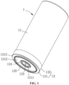
FIG. 1 is a schematic structural diagram of a battery cell according to an embodiment of the present application; -
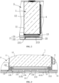
FIG. 2 is a partial cross-sectional view of the battery cell and a tray according to an embodiment of the present application; -
FIG. 3 is a partial cross-sectional view of the battery cell and a partition plate according to an embodiment of the present application; -
FIG. 4 is a schematic structural diagram of a battery pack according to an embodiment of the present application; and -
FIG. 5 is a schematic structural diagram of the battery pack in an exploded view according to an embodiment of the present application. -
- 1. battery cell
- 11. housing
- 12. jelly roll
- 13. blocking member
- 131. sealing cover plate
- 1311. central plate
- 1312. first annular plate
- 1313. second annular plate
- 132. surrounding wall
- 133. protrusion
- 134. first boss
- 135. second boss
- 14. collector plate
- 2. tray
- 21. partition plate
- 211. weak region
- 212. positioning slot
- 213. explosion-proof valve
- 2131. notch
- 2132. third boss
- 22. bottom plate
- 23. pressure relief passage
- 3. CCS assembly
- 4. cooling pipe
- 5. second accommodating chamber
- As shown in
FIG. 1 to FIG. 3 , abattery cell 1 is proposed in this embodiment, which is arranged in a battery pack and adjacent to apressure relief passage 23 in the battery pack. Thebattery cell 1 includes ahousing 11, ajelly roll 12 and a blockingmember 13. Thehousing 11 has a first accommodating chamber with an opening at one end, and thejelly roll 12 is installed in the first accommodating chamber. The blockingmember 13 is an insulating member that is deformable at high temperature. The blockingmember 13 is connected to thehousing 11 and blocks the opening. Aprotrusion 133 is provided on a side of the blockingmember 13 away from thehousing 11. Theprotrusion 133 is arranged to break through aweak region 211 on a side wall of thepressure relief passage 23. It should be noted that the high temperature at which the blockingmember 13 deforms refers to the temperature after thebattery cell 1 has thermal runaway, that is, thebattery cell 1 heats up after thermal runaway occurs, and at this time, the blockingmember 13 is deformed by heat. - By setting the blocking
member 13 as an insulating member that is deformable at high temperature, when thebattery cell 1 has thermal runaway, the blockingmember 13 melts and deforms after being heated, and the airflow in thehousing 11 impacts the blockingmember 13, so that the blockingmember 13 is separated from thehousing 11, and the opening of thehousing 11 is opened to release the pressure inside thebattery cell 1. Since the blockingmember 13 is an insulating member, when the airflow in thebattery cell 1 breaks through the blockingmember 13 to release pressure, the conductive material follows the airflow through thepressure relief passage 23 and is sprayed ontoother battery cells 1. The insulating blockingmember 13 of anyother battery cell 1 separates and insulates the sprayed conductive material from thejelly roll 12 inside it, preventing theother battery cell 1 from being affected and short-circuited. Moreover, when the blockingmember 13 is separated from thehousing 11, arcing between the insulating blockingmember 13 and thehousing 11 is avoided, thereby improving the safety factor of thebattery cell 1 in the thermal runaway state. Furthermore, when thebattery cell 1 has thermal runaway, the gas inside the first accommodating chamber of thehousing 11 expands, and the blockingmember 13 is compressed to squeeze theweak region 211 of the side wall of thepressure relief passage 23, and theprotrusion 133 assists in breaking through theweak region 211, so that the airflow ejected from thebattery cell 1 flows smoothly into thepressure relief passage 23, thereby improving the pressure relief effect and preventing the airflow ejected from thebattery cell 1 from gathering inside the battery pack. - In some embodiments, the material of the
protrusion 133 is consistent with the material of the blockingmember 13, and theprotrusion 133 and the blockingmember 13 are integrally formed, so that the melting point of theprotrusion 133 is consistent with the melting point of the blockingmember 13, which facilitates the integral forming of theprotrusion 133 and the blockingmember 13, and reduces the processing difficulty of thebattery cell 1. In other embodiments, the material of theprotrusion 133 is different from the material of the blockingmember 13, and the melting point of theprotrusion 133 is higher than the melting point of the blockingmember 13, so as to avoid affecting the hardness of theprotrusion 133 after the thermal runaway of thebattery cell 1 occurs, so that theprotrusion 133 with a higher melting point can maintain sufficient strength to break through theweak region 211 for pressure relief. - In this embodiment, the
protrusion 133 and the blockingmember 13 are integrally formed, and the melting point of theprotrusion 133 is consistent with the melting point of the blockingmember 13. Exemplarily, the materials of theprotrusion 133 and the blockingmember 13 may be polycarbonate (PC), polyethylene glycol terephthalate (PET), acrylonitrile butadiene styrene (ABS), PC+ABS, polypropylene (PP), etc. It is understandable that when the blockingmember 13 is heated, due to the large thickness of theprotrusion 133, the heating rate of theprotrusion 133 is lower than the heating rate of other parts of the blockingmember 13 in a short time, that is, the temperature of theprotrusion 133 is lower than the temperature of other parts of the blockingmember 13. At this time, theprotrusion 133 can maintain its original strength so as to break through theweak region 211 of the side wall of thepressure relief passage 23. - In this embodiment, the
housing 11 is a metal part, thehousing 11 is negatively charged, and the material of the blockingmember 13 is plastic cement. In other embodiments, the blockingmember 13 may also be made of other composite materials, and it is only necessary to ensure that the blockingmember 13 is insulated from thehousing 11. - As shown in
FIG. 1 , the blockingmember 13 includes a sealingcover plate 131 and asurrounding wall 132, the surroundingwall 132 and theprotrusion 133 are located on two sides of the sealingcover plate 131 respectively, and the surroundingwall 132 is sleeved on an outer circumference of thehousing 11. An inner side surface of the surroundingwall 132 is connected to an outer surface of thehousing 11, and the inner side surface of the surroundingwall 132 is bonded to the outer surface of thehousing 11 with high-temperature resistant glue. Apparently, the connection between the surroundingwall 132 and thehousing 11 can also be achieved by other connection methods. For example, snap-on connection, sealing ring connection, etc. are used, which are not limited here. The surroundingwall 132 increases the area of connection between the blockingmember 13 and thehousing 11, thereby improving the strength of connection between the two, so that the first accommodating chamber and the outside of thehousing 11 remain isolated under normal conditions, so that thebattery cell 1 can perform normal power charging, storing and discharging operations. In addition, the surroundingwall 132 is sleeved on thehousing 11, which not only reduces the occupation of the first accommodating chamber by the blockingmember 13, but also avoids the surroundingwall 132 from squeezing thejelly roll 12 inside thehousing 11, and also reduces the difficulty of installing the blockingmember 13 and thehousing 11. In other embodiments, the surroundingwall 132 can also be inserted into the first accommodating chamber so that an outer circumferential side surface of the surroundingwall 132 is fixed to an inner side surface of thehousing 11. - As shown in
FIG. 1 , theprotrusion 133 is spike-shaped. Setting theprotrusion 133 in the shape of a spike can reduce the area of contact between theprotrusion 133 and theweak region 211, increase the intensity of pressure applied by theprotrusion 133 to theweak region 211, thereby reducing the difficulty of theprotrusion 133 piercing theweak region 211, so that the airflow ejected from the inside of thehousing 11 during thermal runaway can smoothly enter thepressure relief passage 23. - The
protrusion 133 is located at the center of the sealingcover plate 131 of the blockingmember 13. The outer circumference of the blockingmember 13 is connected to thehousing 11, therefore, when thebattery cell 1 expands, the sealingcover plate 131 will deform (even if the temperature is not high, the sealingcover plate 131 will deform under the influence of air pressure). The center of the sealingcover plate 131 is the region with the largest deformation. When the sealingcover plate 131 is deformed at high temperature, theprotrusion 133 arranged at the center of the sealingcover plate 131 moves the longest distance toward theweak region 211, which helps theprotrusion 133 to quickly pierce theweak region 211, thereby assisting in pressure relief. - As shown in
FIG. 1 , afirst boss 134 is provided on the side of the blockingmember 13 away from thehousing 11. Thefirst boss 134 is annular. Theprotrusion 133 is located in an annular region of thefirst boss 134, and an end face of thefirst boss 134 abuts against theweak region 211. By setting thefirst boss 134, theprotrusion 133 can be assisted to break through theweak region 211, so that thebattery cell 1 can be depressurized smoothly. - Referring to
FIG. 1 to FIG. 3 , the sealingcover plate 131 of the blockingmember 13 includes acentral plate 1311, a firstannular plate 1312 and a secondannular plate 1313. Thecentral plate 1311 is located within an annular region of the firstannular plate 1312, and a circumferential side surface of thecentral plate 1311 is connected to an inner side surface of the firstannular plate 1312. The firstannular plate 1312 is located within an annular region of the secondannular plate 1313, and an outer circumferential side surface of the firstannular plate 1312 is connected to an inner side surface of the secondannular plate 1313. Thefirst boss 134 and theprotrusion 133 are both arranged on thecentral plate 1311, the secondannular plate 1313 abuts against theweak region 211, and the firstannular plate 1312 is spaced from theweak region 211. When thebattery cell 1 has thermal runaway, the high temperature will cause the firstannular plate 1312 to melt and deform. Under the impact of the pressure relief airflow, the firstannular plate 1312 will break, so that thecentral plate 1311 can be driven by the pressure relief airflow to move toward one side of thepressure relief passage 23, thereby allowing theprotrusion 133 and thefirst boss 134 to break through theweak region 211 on thepressure relief passage 23, so that the pressure relief airflow can enter thepressure relief passage 23 to complete the pressure relief. - In this embodiment, the
central plate 1311, the firstannular plate 1312, the secondannular plate 1313, theprotrusion 133, thefirst boss 134 and the surroundingwall 132 are integrally formed, and the thickness of the firstannular plate 1312, the thickness of the secondannular plate 1313 and the thickness of thecentral plate 1311 are equal. It can be understood that the secondannular plate 1313 and thecentral plate 1311 on two sides of the annular region of the firstannular plate 1312 are each in contact with the weak region 211 (thecentral plate 1311 is in contact with theweak region 211 through the first protrusion 133), and the firstannular plate 1312 is suspended. When thebattery cell 1 undergoes thermally runaway and the gas inside thehousing 11 expands, under the action of the internal air pressure, the suspended firstannular plate 1312 is more likely to deform and rupture, to allow thecentral plate 1311 to be separated and impact theweak region 211, so as to puncture theweak region 211, to allow the inside of thehousing 11 to be in communication with thepressure relief passage 23. - Referring to
FIG. 4 andFIG. 5 , a battery pack is further provided according to this embodiment, which includes atray 2 and thebattery cell 1. Thepressure relief passage 23 is provided inside thetray 2, and a side wall of thepressure relief passage 23 has aweak region 211. Thetray 2 is located below thebattery cell 1 and supports thebattery cell 1, and theprotrusion 133 of thebattery cell 1 is directly opposite to theweak region 211. When thebattery cell 1 experiences thermal runaway, the blockingmember 13 will melt and deform due to the heat, to allow the blockingmember 13 to be separated from thehousing 11 to release the pressure inside thebattery cell 1. At this time, the blockingmember 13 squeezes theweak region 211, and theprotrusion 133 assists in breaking through theweak region 211, to allow the airflow ejected from thebattery cell 1 to flow into thepressure relief passage 23 to improve the pressure relief effect and prevent the airflow ejected from thebattery cell 1 from gathering inside the battery pack. - The
tray 2 includes apartition plate 21 and a bottom plate 22, and thepartition plate 21 and the bottom plate 22 are spaced apart to define thepressure relief passage 23 therebetween. Thebattery cell 1 is arranged on a side of thepartition plate 21 away from thepressure relief passage 23, and thepartition plate 21 is provided with theweak region 211. As shown inFIG. 4 ,multiple battery cells 1 are provided and are arranged in an array, and theprotrusion 133 of thebattery cell 1 directly faces theweak region 211 of thepartition plate 21. Since the insulating blockingmember 13 on thebattery cell 1 can insulate thebattery cell 1 from the conductive material sprayed in the thermal runaway state, the battery pack is not prone to short circuit in the thermal runaway state, nor is it prone to explosion due to short circuit, and its safety factor is high. - One of the blocking
member 13 and thepartition plate 21 of thebattery cell 1 is provided with asecond boss 135, the other is provided with apositioning slot 212, and thesecond boss 135 is inserted into thepositioning slot 212. Through the insertion-connection between thesecond boss 135 and thepositioning slot 212, the installation of thebattery cell 1 onto thepartition plate 21 is guided and limited, which reduces the installation difficulty of thebattery cell 1 and thepartition plate 21 and improves the assembly efficiency of the battery pack. - Referring to
FIG. 1 to FIG. 3 , in this embodiment, thesecond boss 135 is arranged on the blockingmember 13, thesecond boss 135 is annular, theprotrusion 133 is located within an annular region of thesecond boss 135, and theweak region 211 is provided with thepositioning slot 212. Thepositioning slot 212 is arranged in thepartition plate 21, and thepositioning slot 212 is a through slot, that is, thepositioning slot 212 passes through thepartition plate 21. In other embodiments, thesecond boss 135 may also be arranged in theweak region 211 of thepartition plate 21, and the blockingmember 13 is correspondingly provided with thepositioning slot 212. - As shown in
FIG. 3 , an explosion-proof valve 213 is arranged in thepositioning slot 212 to achieve the positioning installation of the explosion-proof valve 213. The explosion-proof valve 213 is arranged by being clamped within thepositioning slot 212; or, the explosion-proof valve 213 is welded to thepartition plate 21; or the explosion-proof valve 213 is bonded to thepartition plate 21. By assembling a circumferential side of the explosion-proof valve 213 with a slot wall of thepositioning slot 212 by clamping, welding or bonding, the stability of installation of the explosion-proof valve 213 is improved. - In this embodiment, the explosion-
proof valve 213 is arranged in theweak region 211, and theprotrusion 133 is directly opposite to the explosion-proof valve 213. When thebattery cell 1 undergoes thermally runaway, the gas expanded in thebattery cell 1 and theprotrusion 133 and thefirst boss 134 on thebattery cell 1 can break through the explosion-proof valve 213. This embodiment is equivalent to transferring the original explosion-proof valve 213 on thebattery cell 1 to thetray 2 of the battery pack. By transferring the explosion-proof valve 213 from thebattery cell 1 to thetray 2, in one aspect, the difficulty of assembling thebattery cell 1 can be reduced to avoid accidental squeezing of the explosion-proof valve 213 during assembly, and in another aspect, the difficulty of fixing and installing the explosion-proof valve 213 can be reduced. It can be understood that the structure of thebattery cell 1 is much more complicated than thetray 2. When setting the explosion-proof valve 213 on thetray 2, there is no need to consider the influence of thejelly roll 12, the collector and other structures on the installation position of the explosion-proof valve 213, and only the arrangement position of the explosion-proof valve 213 on thetray 2 is required to be considered, which reduces the difficulty of processing the battery pack. - In this embodiment, the depth of the
positioning slot 212 is greater than the thickness of the explosion-proof valve 213, so as to achieve the spacing arrangement of the explosion-proof valve 213 and the blockingmember 13. The separated explosion-proof valve 213 andtray 2 reduce the processing difficulty of the battery pack, thereby reducing the production cost of the battery pack. The depth of thepositioning slot 212 is greater than the thickness of the explosion-proof valve 213, thus, the explosion-proof valve 213 can be arranged at an end of thepositioning slot 212 away from thebattery cell 1 to achieve the spacing arrangement of the explosion-proof valve 213 and thebattery cell 1, and it can also ensure that the explosion-proof valve 213 is completely located within thepositioning slot 212. - The diameter of the
positioning slot 212 is smaller than the diameter of the sealingcover plate 131, and an edge of the sealingcover plate 131 abuts against thetray 2. When thebattery cell 1 has thermal runaway, the central region of the sealingcover plate 131 ruptures. Since the diameter of thepositioning slot 212 is smaller than the diameter of the sealingcover plate 131, the explosion-proof valve 213 is prevented from directly providing support force for thebattery cell 1, thereby preventing the explosion-proof valve 213 from being damaged under the squeeze of other external forces. In this embodiment, since the edge of the sealingcover plate 131 abuts against thetray 2, the central region of the sealingcover plate 131 is in a suspended state. When thebattery cell 1 experiences thermal runaway, the central region of the suspended sealingcover plate 131 is more likely to deform. Under the continuous action of the expanding gas, the central region of the sealingcover plate 131 will be damaged, thereby releasing the pressure inside thebattery cell 1. It can be understood that the ejected gas is radial, and the ejected gas will spread around the center of the sealingcover plate 131. By setting the central region of the sealingcover plate 131 in a suspended state, the cracks of the sealingcover plate 131 are concentrated in its central region, which can ensure that the main path direction of the ejected gas is toward the explosion-proof valve 213, so that the ejected gas can smoothly enter thepressure relief passage 23 to complete the pressure relief. - The
protrusion 133 is arranged to be spaced apart from theweak region 211. When in use, the battery pack will shake with the environment, and at this time, thebattery cell 1 will also move accordingly. Since theprotrusion 133 is spike-shaped, it is easier for theprotrusion 133 to puncture theweak region 211 than thefirst boss 134. Therefore, theprotrusion 133 is arranged to be spaced apart from theweak region 211 to avoid theprotrusion 133 from puncturing theweak region 211 by mistake under normal circumstances. Arranging theprotrusion 133 to be spaced apart from theweak region 211 may further provide processing allowance and assembly allowance for the production of the battery pack to avoid thebattery cell 1 from puncturing theweak region 211 during the assembly process, thereby improving the yield rate of the battery. - In this embodiment, the explosion-
proof valve 213 is provided with anotch 2131. When the explosion-proof valve 213 is under pressure, thenotch 2131 is broken and deformed by being squeezed, so that the first accommodating chamber comes into airflow communication with thepressure relief passage 23 in thebattery cell 1. - The explosion-
proof valve 213 is further provided with a stampedthird boss 2132 which is annular and abuts against thefirst boss 134. Thethird boss 2132 can reduce the thickness of thefirst boss 134, to allow an end surface of thefirst boss 134 to be flush with theprotrusion 133, thereby reducing the difficulty of processing the blockingmember 13. In the case where the end surface of thefirst boss 134 is flush with theprotrusion 133, thethird boss 2132 can also separate theprotrusion 133 and the explosion-proof valve 213, so as to prevent theprotrusion 133 from accidentally puncturing the explosion-proof valve 213 in normal use. - In this embodiment, as shown in
FIG. 4 , the battery pack further includes a cell connection system (CCS)assembly 3, a secondaccommodating chamber 5 is formed between theCCS assembly 3 and thepartition plate 21, thebattery cells 1 are arranged in array in the secondaccommodating chamber 5, and the collector plate of theCCS assembly 3 is electrically connected to thebattery cells 1 to output after collecting the currents of thebattery cells 1. - As shown in
FIG. 5 , acooling pipe 4 is further provided in the battery pack, and thecooling pipe 4 is provided between two adjacent columns ofbattery cells 1, and is arranged to cool thebattery cells 1. The first accommodating chamber of thehousing 11 of thebattery cell 1 is provided with not only ajelly roll 12 but also acollector plate 14, and thecollector plate 14 is connected to each of thejelly roll 12 and thehousing 11 to make thehousing 11 negatively charged.
Claims (13)
- A battery cell, comprising:a housing, wherein the housing has a first accommodating chamber with an opening at one end; anda blocking member, wherein the blocking member is an insulating member deformable at high temperature, the blocking member is connected to the housing and blocks the opening, the blocking member is provided with a protrusion on a side of the blocking member away from the housing, and the protrusion is arranged to break through a weak region on a pressure relief passage.
- The battery cell according to claim 1, wherein the protrusion is spike-shaped; the protrusion is located at a center of the blocking member; or the protrusion is spike-shaped and located at the center of the blocking member.
- The battery cell according to claim 1, wherein the blocking member is provided with a first boss on a side of the blocking member away from the housing, the first boss is annular, the protrusion is located in an annular region of the first boss, and an end face of the first boss abuts against the weak region.
- The battery cell according to claim 3, wherein the blocking member comprises a sealing cover plate, the sealing cover plate comprises a central plate, a first annular plate and a second annular plate, the central plate is located within an annular region of the first annular plate, a circumferential side surface of the central plate is connected to an inner side surface of the first annular plate, the first annular plate is located within an annular region of the second annular plate, an outer circumferential side surface of the first annular plate is connected to an inner side surface of the second annular plate, the first boss and the protrusion are both arranged on the central plate, the second annular plate abuts against the weak region, the first annular plate is spaced from the weak region, and the first annular plate is arranged to break and the central plate is arranged to move toward the pressure relief passage in the event of thermal runaway of the battery cell.
- The battery cell according to any one of claims 1 to 4, wherein the protrusion is made of a same material as the blocking member; or
the protrusion is made of a different material from the blocking member, and a melting point of the protrusion is higher than a melting point of the blocking member. - The battery cell according to any one of claims 1 to 4, wherein the blocking member comprises a sealing cover plate and a surrounding wall, the surrounding wall and the protrusion are located on two sides of the sealing cover plate respectively, and the surrounding wall is sleeved on an outer circumference of the housing.
- A battery pack, comprising:a tray and the battery cell according to any one of claims 1 to 6,wherein a pressure relief passage is provided inside the tray, a side wall of the pressure relief passage has a weak region, the tray is located below the battery cell and supports the battery cell, and the protrusion of the battery cell is directly opposite to the weak region.
- The battery pack according to claim 7, wherein the tray comprises a bottom plate and a partition plate, the bottom plate and the partition plate are spaced to define the pressure relief passage, the battery cell is arranged on a side of the partition plate away from the pressure relief passage, and the partition plate is provided with the weak region.
- The battery pack according to claim 8, wherein one of the blocking member of the battery cell and the partition plate is provided with a second boss, and an other of the blocking member of the battery cell and the partition plate is provided with a positioning slot, and the second boss is inserted into the positioning slot.
- The battery pack according to claim 9, wherein the second boss is arranged on the blocking member, the second boss is annular, and the protrusion is located within an annular region of the second boss; and the weak region is provided with the positioning slot.
- The battery pack according to claim 10, further comprising an explosion-proof valve, wherein the explosion-proof valve is arranged by being clamped in the positioning slot; the explosion-proof valve is welded to the partition plate; or the explosion-proof valve is bonded to the partition plate; and
the protrusion is directly opposite to the explosion-proof valve. - The battery pack according to claim 11, wherein a depth of the positioning slot is greater than a thickness of the explosion-proof valve.
- The battery pack according to claim 7, wherein the protrusion is arranged to be spaced apart from the weak region.
Applications Claiming Priority (4)
| Application Number | Priority Date | Filing Date | Title |
|---|---|---|---|
| CN202310858436.3A CN116914366B (en) | 2023-07-12 | 2023-07-12 | battery pack |
| CN202321831926.6U CN220439751U (en) | 2023-07-12 | 2023-07-12 | Battery cell and battery pack |
| CN202321839763.6U CN220604896U (en) | 2023-07-12 | 2023-07-12 | Battery pack |
| PCT/CN2024/104128 WO2024245455A1 (en) | 2023-07-12 | 2024-07-08 | Battery cell and battery pack |
Publications (2)
| Publication Number | Publication Date |
|---|---|
| EP4507101A1 true EP4507101A1 (en) | 2025-02-12 |
| EP4507101A4 EP4507101A4 (en) | 2025-12-17 |
Family
ID=93656745
Family Applications (1)
| Application Number | Title | Priority Date | Filing Date |
|---|---|---|---|
| EP24798204.4A Pending EP4507101A4 (en) | 2023-07-12 | 2024-07-08 | BATTERY ELEMENT AND BATTERY BLOCK |
Country Status (3)
| Country | Link |
|---|---|
| US (1) | US20250046943A1 (en) |
| EP (1) | EP4507101A4 (en) |
| WO (1) | WO2024245455A1 (en) |
Family Cites Families (8)
| Publication number | Priority date | Publication date | Assignee | Title |
|---|---|---|---|---|
| CN110400895B (en) * | 2019-07-30 | 2021-03-09 | 宁德时代新能源科技股份有限公司 | Battery module, secondary battery and top cover assembly thereof |
| CN211555941U (en) * | 2019-12-31 | 2020-09-22 | 江苏境具净环保科技有限公司 | Battery structure |
| CN214625297U (en) * | 2021-03-25 | 2021-11-05 | 江苏正力新能电池技术有限公司 | Integrated flame-retardant structure, top cover and battery |
| DE102021118068A1 (en) * | 2021-07-13 | 2023-01-19 | Elringklinger Ag | Cover for a battery module or for a battery storage |
| CN218182409U (en) * | 2022-05-11 | 2022-12-30 | 江苏正力新能电池技术有限公司 | A pressure-relief pole assembly, a battery top cover and a power battery |
| CN218101550U (en) * | 2022-08-29 | 2022-12-20 | 中创新航科技股份有限公司 | Battery holders and battery units |
| CN220439751U (en) * | 2023-07-12 | 2024-02-02 | 惠州亿纬锂能股份有限公司 | Battery cell and battery pack |
| CN116914366B (en) * | 2023-07-12 | 2026-01-30 | 惠州亿纬锂能股份有限公司 | battery pack |
-
2024
- 2024-07-08 EP EP24798204.4A patent/EP4507101A4/en active Pending
- 2024-07-08 WO PCT/CN2024/104128 patent/WO2024245455A1/en active Pending
- 2024-10-22 US US18/923,197 patent/US20250046943A1/en active Pending
Also Published As
| Publication number | Publication date |
|---|---|
| US20250046943A1 (en) | 2025-02-06 |
| WO2024245455A1 (en) | 2024-12-05 |
| EP4507101A4 (en) | 2025-12-17 |
Similar Documents
| Publication | Publication Date | Title |
|---|---|---|
| CN115699437B (en) | Battery cell and manufacturing method and system thereof, battery and electric device | |
| CN213584016U (en) | Batteries, electrical devices and devices for producing batteries | |
| EP3540815B1 (en) | Battery module | |
| CN214898799U (en) | End cover assembly, battery and power consumption device | |
| US9692025B2 (en) | Battery cap assembly with high efficiency vent | |
| CN214254572U (en) | Battery cell, battery and power consumption device | |
| KR20220013577A (en) | Battery, electricity using device, battery manufacturing method and device | |
| WO2021017905A1 (en) | Battery, battery cell, and top cover assembly thereof | |
| WO2022006891A1 (en) | Battery, electric device, and method and device for preparing battery | |
| WO2023137976A1 (en) | Battery cell, battery and electric device | |
| CN220543989U (en) | Battery cells, batteries and electrical devices | |
| CN116914366B (en) | battery pack | |
| KR20220016502A (en) | Battery, electricity using device, battery manufacturing method and device | |
| JP2023522801A (en) | BATTERY CASE, BATTERY, POWER CONSUMING DEVICE, CASE MANUFACTURING METHOD AND APPARATUS | |
| US20100330402A1 (en) | Cap assembly with desirable safety performance | |
| KR102890243B1 (en) | Batteries, electrical devices, methods and devices for manufacturing batteries | |
| WO2021012912A1 (en) | Top cover assembly, secondary battery, and apparatus using battery | |
| EP4207459B1 (en) | Pressure relief mechanism, battery cell, battery, electrical device, and pressure relief mechanism manufacturing method | |
| WO2020133662A1 (en) | Secondary battery and battery module | |
| WO2024016158A1 (en) | Battery cell end cover assembly, battery cell, battery, and electric device | |
| EP4148887A1 (en) | Cap assembly and secondary battery including same | |
| CN116529942A (en) | Battery cell, manufacturing method and manufacturing system thereof, battery and electricity utilization device | |
| CN106972119B (en) | A cover plate assembly, battery and battery pack containing the same | |
| EP4507101A1 (en) | Battery cell and battery pack | |
| JP2023546634A (en) | Pressure relief mechanism, battery cell, battery, power consumption device and manufacturing method thereof |
Legal Events
| Date | Code | Title | Description |
|---|---|---|---|
| STAA | Information on the status of an ep patent application or granted ep patent |
Free format text: STATUS: UNKNOWN |
|
| STAA | Information on the status of an ep patent application or granted ep patent |
Free format text: STATUS: THE INTERNATIONAL PUBLICATION HAS BEEN MADE |
|
| PUAI | Public reference made under article 153(3) epc to a published international application that has entered the european phase |
Free format text: ORIGINAL CODE: 0009012 |
|
| STAA | Information on the status of an ep patent application or granted ep patent |
Free format text: STATUS: REQUEST FOR EXAMINATION WAS MADE |
|
| 17P | Request for examination filed |
Effective date: 20241104 |
|
| AK | Designated contracting states |
Kind code of ref document: A1 Designated state(s): AL AT BE BG CH CY CZ DE DK EE ES FI FR GB GR HR HU IE IS IT LI LT LU LV MC ME MK MT NL NO PL PT RO RS SE SI SK SM TR |
|
| A4 | Supplementary search report drawn up and despatched |
Effective date: 20251114 |
|
| RIC1 | Information provided on ipc code assigned before grant |
Ipc: H01M 50/342 20210101AFI20251110BHEP |