EP4507073A1 - Electrochemical apparatus, battery module and electronic device - Google Patents
Electrochemical apparatus, battery module and electronic device Download PDFInfo
- Publication number
- EP4507073A1 EP4507073A1 EP22936185.2A EP22936185A EP4507073A1 EP 4507073 A1 EP4507073 A1 EP 4507073A1 EP 22936185 A EP22936185 A EP 22936185A EP 4507073 A1 EP4507073 A1 EP 4507073A1
- Authority
- EP
- European Patent Office
- Prior art keywords
- edge
- seal portion
- lateral face
- main body
- seal
- Prior art date
- Legal status (The legal status is an assumption and is not a legal conclusion. Google has not performed a legal analysis and makes no representation as to the accuracy of the status listed.)
- Pending
Links
Images

Classifications
-
- H—ELECTRICITY
- H01—ELECTRIC ELEMENTS
- H01M—PROCESSES OR MEANS, e.g. BATTERIES, FOR THE DIRECT CONVERSION OF CHEMICAL ENERGY INTO ELECTRICAL ENERGY
- H01M50/00—Constructional details or processes of manufacture of the non-active parts of electrochemical cells other than fuel cells, e.g. hybrid cells
- H01M50/10—Primary casings; Jackets or wrappings
- H01M50/183—Sealing members
- H01M50/186—Sealing members characterised by the disposition of the sealing members
-
- H—ELECTRICITY
- H01—ELECTRIC ELEMENTS
- H01M—PROCESSES OR MEANS, e.g. BATTERIES, FOR THE DIRECT CONVERSION OF CHEMICAL ENERGY INTO ELECTRICAL ENERGY
- H01M10/00—Secondary cells; Manufacture thereof
- H01M10/04—Construction or manufacture in general
- H01M10/0431—Cells with wound or folded electrodes
-
- H—ELECTRICITY
- H01—ELECTRIC ELEMENTS
- H01M—PROCESSES OR MEANS, e.g. BATTERIES, FOR THE DIRECT CONVERSION OF CHEMICAL ENERGY INTO ELECTRICAL ENERGY
- H01M50/00—Constructional details or processes of manufacture of the non-active parts of electrochemical cells other than fuel cells, e.g. hybrid cells
- H01M50/10—Primary casings; Jackets or wrappings
- H01M50/102—Primary casings; Jackets or wrappings characterised by their shape or physical structure
- H01M50/103—Primary casings; Jackets or wrappings characterised by their shape or physical structure prismatic or rectangular
-
- H—ELECTRICITY
- H01—ELECTRIC ELEMENTS
- H01M—PROCESSES OR MEANS, e.g. BATTERIES, FOR THE DIRECT CONVERSION OF CHEMICAL ENERGY INTO ELECTRICAL ENERGY
- H01M50/00—Constructional details or processes of manufacture of the non-active parts of electrochemical cells other than fuel cells, e.g. hybrid cells
- H01M50/10—Primary casings; Jackets or wrappings
- H01M50/102—Primary casings; Jackets or wrappings characterised by their shape or physical structure
- H01M50/105—Pouches or flexible bags
-
- H—ELECTRICITY
- H01—ELECTRIC ELEMENTS
- H01M—PROCESSES OR MEANS, e.g. BATTERIES, FOR THE DIRECT CONVERSION OF CHEMICAL ENERGY INTO ELECTRICAL ENERGY
- H01M50/00—Constructional details or processes of manufacture of the non-active parts of electrochemical cells other than fuel cells, e.g. hybrid cells
- H01M50/10—Primary casings; Jackets or wrappings
- H01M50/172—Arrangements of electric connectors penetrating the casing
- H01M50/174—Arrangements of electric connectors penetrating the casing adapted for the shape of the cells
- H01M50/176—Arrangements of electric connectors penetrating the casing adapted for the shape of the cells for prismatic or rectangular cells
-
- H—ELECTRICITY
- H01—ELECTRIC ELEMENTS
- H01M—PROCESSES OR MEANS, e.g. BATTERIES, FOR THE DIRECT CONVERSION OF CHEMICAL ENERGY INTO ELECTRICAL ENERGY
- H01M50/00—Constructional details or processes of manufacture of the non-active parts of electrochemical cells other than fuel cells, e.g. hybrid cells
- H01M50/10—Primary casings; Jackets or wrappings
- H01M50/172—Arrangements of electric connectors penetrating the casing
- H01M50/174—Arrangements of electric connectors penetrating the casing adapted for the shape of the cells
- H01M50/178—Arrangements of electric connectors penetrating the casing adapted for the shape of the cells for pouch or flexible bag cells
-
- H—ELECTRICITY
- H01—ELECTRIC ELEMENTS
- H01M—PROCESSES OR MEANS, e.g. BATTERIES, FOR THE DIRECT CONVERSION OF CHEMICAL ENERGY INTO ELECTRICAL ENERGY
- H01M50/00—Constructional details or processes of manufacture of the non-active parts of electrochemical cells other than fuel cells, e.g. hybrid cells
- H01M50/10—Primary casings; Jackets or wrappings
- H01M50/183—Sealing members
- H01M50/184—Sealing members characterised by their shape or structure
-
- H—ELECTRICITY
- H01—ELECTRIC ELEMENTS
- H01M—PROCESSES OR MEANS, e.g. BATTERIES, FOR THE DIRECT CONVERSION OF CHEMICAL ENERGY INTO ELECTRICAL ENERGY
- H01M50/00—Constructional details or processes of manufacture of the non-active parts of electrochemical cells other than fuel cells, e.g. hybrid cells
- H01M50/50—Current conducting connections for cells or batteries
- H01M50/543—Terminals
- H01M50/547—Terminals characterised by the disposition of the terminals on the cells
- H01M50/55—Terminals characterised by the disposition of the terminals on the cells on the same side of the cell
-
- Y—GENERAL TAGGING OF NEW TECHNOLOGICAL DEVELOPMENTS; GENERAL TAGGING OF CROSS-SECTIONAL TECHNOLOGIES SPANNING OVER SEVERAL SECTIONS OF THE IPC; TECHNICAL SUBJECTS COVERED BY FORMER USPC CROSS-REFERENCE ART COLLECTIONS [XRACs] AND DIGESTS
- Y02—TECHNOLOGIES OR APPLICATIONS FOR MITIGATION OR ADAPTATION AGAINST CLIMATE CHANGE
- Y02E—REDUCTION OF GREENHOUSE GAS [GHG] EMISSIONS, RELATED TO ENERGY GENERATION, TRANSMISSION OR DISTRIBUTION
- Y02E60/00—Enabling technologies; Technologies with a potential or indirect contribution to GHG emissions mitigation
- Y02E60/10—Energy storage using batteries
Definitions
- This application relates to the technical field of energy storage, and in particular, to an electrochemical device, a battery module, and an electronic device.
- an electrochemical device typically includes an electrode assembly and an aluminum laminated film that wraps the electrode assembly.
- the edges of the aluminum laminated film usually need to be sealed so that an electrolyte solution can be carried inside a housing formed by the aluminum laminated film.
- the edges of the housing occupy some space, thereby resulting in a decrease in energy density and bringing inconvenience.
- a main objective to be achieved by this application is to provide an electrochemical device, a battery module, and an electronic device to reduce the area occupied by the electrochemical device and increase the energy density.
- the electrochemical device includes an electrode assembly, a tab, and a housing.
- the housing includes a main body.
- the electrode assembly is accommodated in the housing.
- One end of the tab is connected to the electrode assembly.
- Another end of the tab extends out from a first lateral face of the main body.
- the housing includes a tail seal portion, a first connecting portion, and a first side seal portion.
- the tail seal portion is connected to a second lateral face of the main body.
- the first side seal portion is connected to a third lateral face of the main body.
- the first lateral face and the second lateral face are disposed opposite to each other.
- the third lateral face is located between the second lateral face and the first lateral face.
- the first side seal portion is connected to the tail seal portion by the first connecting portion.
- the tail seal portion is configured to be folded in a first direction
- the first side seal portion is configured to be folded in a second direction, so that the first connecting portion closely fits the second lateral face of the main body.
- the first direction is perpendicular to a direction from the first lateral face to the second lateral face, and the first direction is opposite to the second direction.
- the first connecting portion includes a first part.
- the first part is an overlap part at which the first connecting portion overlaps the tail seal portion.
- the first part includes a first edge.
- the first edge is an end edge by which the first connecting portion is connected to the tail seal portion.
- the tail seal portion includes a first seal edge.
- the first seal edge is an end edge by which the tail seal portion is concatenated to the main body.
- An angle between the first edge and the first seal edge is ⁇ , and the angle ⁇ is less than 90°.
- the angle ⁇ ranges from 30° to 60°.
- the first connecting portion further includes a second part.
- the second part is connected to the first part.
- the second part includes a second edge and a third edge disposed opposite to each other.
- the third edge is an end edge by which the second part is connected to the first part.
- the main body includes a first surface.
- the first surface is an end face of the main body, the end face being closest to the second edge in the second direction.
- a distance between the second edge and the third edge is d 1
- a distance between the third edge and the first surface is d 2 , satisfying: d 2 ⁇ d 1 .
- the tail seal portion further includes a second seal edge.
- the second seal edge and the first seal edge are two edges disposed opposite to each other.
- the main body further includes a second surface.
- the second surface is an end face of the main body, the end face being closest to the second seal edge in the first direction.
- a distance between the first seal edge and the second seal edge is d 3
- a distance between the first seal edge and the second surface is d 4 , satisfying: d 4 ⁇ d 3 .
- the first side seal portion includes a third seal edge and a fourth seal edge disposed opposite to each other.
- the third seal edge is an end edge by which the first side seal portion is concatenated to the main body.
- a distance between the third seal edge and the fourth seal edge is d 5
- a distance between the third seal edge and the first surface is d 6 , satisfying: d 6 ⁇ d 5 .
- the main body includes a fourth lateral face.
- the fourth lateral face is disposed opposite to the third lateral face.
- the housing further includes a second connecting portion and a second side seal portion.
- the second side seal portion is connected to the fourth lateral face of the main body, and the second side seal portion is connected to the tail seal portion by the second connecting portion.
- the second side seal portion is configured to be folded in the second direction, so that the second connecting portion closely fits the second lateral face of the main body.
- the housing further includes a top seal portion.
- the top seal portion is connected to the first lateral face of the main body.
- the top seal portion and the tail seal portion are located at two opposite ends of the main body respectively.
- One end of the tab is connected to the electrode assembly, and another end of the tab passes out of the housing from the top seal portion.
- the electrode assembly includes a first electrode plate, a second electrode plate, and a separator.
- the separator is located between the first electrode plate and the second electrode plate.
- the first electrode plate, the separator, and the second electrode plate are stacked and wound.
- the battery module includes the electrochemical device disclosed in any one of the above embodiments.
- the electronic device includes the electrochemical device disclosed in any one of the above embodiments or the battery module.
- the electrochemical device provided in this application includes an electrode assembly, a tab, and a housing.
- the housing includes a main body.
- the electrode assembly is accommodated in the housing.
- One end of the tab is connected to the electrode assembly, and another end of the tab extends out from a first lateral face of the main body.
- the housing further includes a tail seal portion, a first connecting portion, and a first side seal portion.
- the tail seal portion is connected to a second lateral face of the main body.
- the first side seal portion is connected to a third lateral face of the main body.
- the first lateral face and the second lateral face are disposed opposite to each other.
- the third lateral face is located between the second lateral face and the first lateral face.
- the first side seal portion is connected to the tail seal portion by the first connecting portion.
- the tail seal portion is configured to be folded in a first direction
- the first side seal portion is configured to be folded in a second direction, so that the first connecting portion closely fits the second lateral face of the main body.
- the first direction is perpendicular to a direction from the first lateral face to the second lateral face, and the first direction is opposite to the second direction.
- the tail seal portion, the first connecting portion, and the first side seal portion of the housing can fit onto the main body by folding, thereby reducing the area occupied by the electrochemical device. When being mounted, other components do not need to avoid the housing, thereby increasing the energy density.
- an element referred to herein as being “fixed to” another element may be directly disposed on the other element, or may be fixed to the other element with one or more elements in between.
- An element referred to herein as “connected to” another element may be connected to the other element directly or with one or more elements in between.
- the terms “vertical”, “horizontal”, “left”, “right”, and other similar expressions used herein are merely for ease of description.
- an embodiment of this application provides an electrochemical device 100.
- the electrochemical device 100 includes a housing 10, an electrode assembly (not shown in the drawing), and a tab 20.
- the electrode assembly is accommodated in the housing 10.
- One end of the tab 20 is connected to the electrode assembly, and another end of the tab 20 extends out from the main body 11, and extends to the outside of the housing 10.
- the housing 10 includes a main body 11, a tail seal portion 12, a first connecting portion 13, and a first side seal portion 14.
- the electrode assembly is accommodated in the main body 11.
- the main body 11 includes a first lateral face 111, a second lateral face 112, a third lateral face 113, a fourth lateral face 114, a first surface 115, and a second surface 116.
- the first lateral face 111 is disposed opposite to the second lateral face 112
- the third lateral face 113 is disposed opposite to the fourth lateral face 114.
- the third lateral face 113 and the fourth lateral face 114 are located between the second lateral face 112 and the first lateral face 111.
- the first surface 115 is disposed opposite to the second surface 116.
- the first surface 115 and the second surface 116 each are connected to the first lateral face 111, the second lateral face 112, the third lateral face 113, and the fourth lateral face 114.
- the other end of the tab 20 extends out from the first lateral face 111 of the main body 11.
- the tail seal portion 12 is connected to the second lateral face 112 of the main body 11.
- the first side seal portion 14 is connected to the third lateral face 113 of the main body 11.
- the first side seal portion 14 is connected to the tail seal portion 12 by the first connecting portion 13.
- the tail seal portion 12 is configured to be folded in a first direction X
- the first side seal portion 14 is configured to be folded in a second direction Y, so that the first connecting portion 13 closely fits the second lateral face 112 of the main body 11.
- the first direction X is perpendicular to a direction from the first lateral face 111 to the second lateral face 112, and the first direction X is opposite to the second direction Y.
- the bending direction of the first side seal portion 14 is opposite to the bending direction of the tail seal portion 12.
- the tail seal portion 12 includes a first seal edge 121 and a second seal edge 122.
- the first seal edge 121 is an end edge by which the tail seal portion 12 is concatenated to the main body 11.
- the second seal edge 122 is disposed opposite to the first seal edge 121.
- the second seal edge 122 is closer to the second surface 116 than the first seal edge 121.
- the second surface 116 is an end face of the main body 11, the end face being closest to the second seal edge 122 in the first direction X.
- the length of the first seal edge 121 is greater than the length of the second seal edge 122.
- the tail seal portion 12 is trapezoidal in shape.
- a distance between the first seal edge 121 and the second seal edge 122 is d 3
- a distance between the first seal edge 121 and the second surface 116 is d 4 , satisfying: d 4 ⁇ d 3 .
- the tail seal portion 12 is prevented from protruding beyond the second surface 116 of the main body 11 along the first direction X.
- the prevention of the tail seal portion 12 from protruding beyond the second surface 116 of the main body 11 along the first direction X can reduce the area occupied by the electrochemical device 100 and favorably increase the energy density.
- the first connecting portion 13 includes a first part 131 and a second part 132.
- the first part 131 is an overlap part at which the first connecting portion 13 overlaps the tail seal portion 12.
- the second part 132 is connected to the first part 131.
- the other end of the second part 132 is connected to the first side seal portion 14.
- the cross-section of the first part 131 along the first direction X is triangular in shape.
- the first part 131 includes a first edge 1311.
- the first edge 1311 is an end edge by which the first connecting portion 13 is connected to the tail seal portion 12.
- An angle between the first edge 1311 and the first seal edge 121 is ⁇ , and the angle ⁇ is less than 90°. In some embodiments, the angle ⁇ ranges from 30° to 60°.
- the cross-section of the second part 132 along the first direction X is rectangular in shape.
- the second part 132 includes a second edge 1321 and a third edge 1322 disposed opposite to each other.
- the third edge 1322 is an end edge by which the second part 132 is connected to the first part 131.
- the second edge 1321 is closer to the first surface 115 than the third edge 1322.
- the first surface 115 is an end face of the main body 11, the end face being closest to the second edge 1321 in the second direction Y.
- a distance between the second edge 1321 and the third edge 1322 is d 1
- a distance between the third edge 1322 and the first surface 115 is d 2 , satisfying: d 2 ⁇ d 1 .
- the first side seal portion 14 includes a third seal edge 141 and a fourth seal edge 142 disposed opposite to each other.
- the third seal edge 141 is an end edge by which the first side seal portion 14 is concatenated to the main body 11.
- the cross-section of the first side seal portion 14 along the first direction X is rectangular in shape.
- a distance between the third seal edge 141 and the fourth seal edge 142 is d 5
- a distance between the third seal edge 141 and the first surface 115 is d 6 , satisfying: d 6 ⁇ d 5 .
- the shape of the electrochemical device 100 in the drawing of the above embodiment is a regular hexahedron, this application is not limited to the illustrated example. In other embodiments of this application, the electrochemical device 100 and the housing 10 may be other shapes instead, as long as the tail seal portion 12, the first connecting portion 13, and the first side seal portion 14 thereof can be folded to fit onto the main body 11 during bending.
- the energy density can still be increased as long as the following conditions are met: the tail seal portion and the first side seal portion are connected to two adjacent surfaces of the main body respectively, and the tail seal portion and the first side seal portion are folded in opposite directions to fit onto the two adjacent surfaces respectively, and the first connecting portion connected to the tail seal portion and the first side seal portion is folded to closely fit any one of the two adjacent surfaces.
- the housing 10 further includes a second connecting portion 15 and a second side seal portion 16.
- the second side seal portion 16 is connected to the fourth lateral face 114 of the main body 11.
- the second side seal portion 16 is connected to the tail seal portion 12 by the second connecting portion 15.
- the second side seal portion 16 is configured to be folded in the second direction Y, so that the second connecting portion 15 closely fits the second lateral face 112 of the main body 11, thereby reducing the area occupied by the electrochemical device 100 and favorably increasing the energy density.
- the structure of the second connecting portion 15 is similar to that of the first connecting portion 13, and is not described in detail here.
- the electrode assembly includes a first electrode plate (not shown in the drawing), a second electrode plate (not shown in the drawing), and a separator (not shown in the drawing).
- the separator is located between the first electrode plate and the second electrode plate. The first electrode plate, the separator, and the second electrode plate are stacked and wound.
- the housing 10 further includes a top seal portion 17.
- the top seal portion 17 is connected to the first lateral face 111 of the main body 11.
- the top seal portion 17 and the tail seal portion 12 are located at two opposite ends of the main body 11 respectively.
- one end of one tab is connected to the first electrode plate, and one end of the other tab is connected to the second electrode plate.
- the other end of one tab and the other end of the other tab pass out of the housing 10 through the first lateral face 111 of the main body 11 and the top seal portion 17.
- the electrochemical device 100 provided in an embodiment of this application includes an electrode assembly, a tab 20, and a housing 10.
- the housing 10 includes a main body 11.
- the electrode assembly is accommodated in the main body 11.
- One end of the tab 20 is connected to the electrode assembly, and another end of the tab 20 extends out from a first lateral face 111 of the main body 11.
- the housing 10 further includes a tail seal portion 12, a first connecting portion 13, and a first side seal portion 14.
- the tail seal portion 12 is connected to a second lateral face 112 of the main body 11.
- the first side seal portion 14 is connected to a third lateral face 113 of the main body 11.
- the first lateral face 111 and the second lateral face 112 are disposed opposite to each other.
- the third lateral face 113 is located between the second lateral face 112 and the first lateral face 111.
- the first side seal portion 14 is connected to the tail seal portion 12 by the first connecting portion 13.
- the tail seal portion 12 is configured to be folded in a first direction X
- the first side seal portion 14 is configured to be folded in a second direction Y, so that the first connecting portion 13 closely fits the second lateral face 112 of the main body 11.
- the first direction X is perpendicular to a direction from the first lateral face 111 to the second lateral face 112, and the first direction X is opposite to the second direction Y. In this way, the main body 11 of the housing 10 can accommodate the electrode assembly.
- the tail seal portion 12, the first connecting portion 13, and the first side seal portion 14 of the housing 10 can fit onto the main body 11 by folding, thereby reducing the area occupied by the electrochemical device 100. When being mounted, other components do not need to avoid the housing 10, thereby increasing the energy density.
- An embodiment of this application further provides a battery module.
- the battery module includes the electrochemical device 100.
- the structure of the electrochemical device 100 may be learned by referring to the above embodiment, details of which are omitted here.
- An embodiment of this application further provides an electronic device.
- the electronic device includes the electrochemical device 100 or the battery module.
- the structure of the electrochemical device 100 or the battery module may be learned by referring to the above embodiment, details of which are omitted here.
- the electronic device is a mobile phone. Understandably, in other embodiments of this application, the electronic device may be a tablet computer, a computer, an unmanned aerial vehicle, or another electrical device that needs to be powered by electricity.
Landscapes
- Chemical & Material Sciences (AREA)
- Chemical Kinetics & Catalysis (AREA)
- Electrochemistry (AREA)
- General Chemical & Material Sciences (AREA)
- Engineering & Computer Science (AREA)
- Manufacturing & Machinery (AREA)
- Sealing Battery Cases Or Jackets (AREA)
- Connection Of Batteries Or Terminals (AREA)
Abstract
Description
- This application relates to the technical field of energy storage, and in particular, to an electrochemical device, a battery module, and an electronic device.
- With the rapid development of electronic products and electric tool industries, many electronic products such as mobile phones are developing a trend toward portability and miniaturization. The space left for an electrochemical device in such electronic products is increasingly limited. Therefore, how to increase the energy density of the electrochemical device in a limited space is becoming increasingly important. Currently, an electrochemical device typically includes an electrode assembly and an aluminum laminated film that wraps the electrode assembly. The edges of the aluminum laminated film usually need to be sealed so that an electrolyte solution can be carried inside a housing formed by the aluminum laminated film. However, the edges of the housing occupy some space, thereby resulting in a decrease in energy density and bringing inconvenience.
- A main objective to be achieved by this application is to provide an electrochemical device, a battery module, and an electronic device to reduce the area occupied by the electrochemical device and increase the energy density.
- To achieve the above objective, a technical solution disclosed in this application is to provide an electrochemical device. The electrochemical device includes an electrode assembly, a tab, and a housing. The housing includes a main body. The electrode assembly is accommodated in the housing. One end of the tab is connected to the electrode assembly. Another end of the tab extends out from a first lateral face of the main body. The housing includes a tail seal portion, a first connecting portion, and a first side seal portion. The tail seal portion is connected to a second lateral face of the main body. The first side seal portion is connected to a third lateral face of the main body. The first lateral face and the second lateral face are disposed opposite to each other. The third lateral face is located between the second lateral face and the first lateral face. The first side seal portion is connected to the tail seal portion by the first connecting portion. The tail seal portion is configured to be folded in a first direction, and the first side seal portion is configured to be folded in a second direction, so that the first connecting portion closely fits the second lateral face of the main body. The first direction is perpendicular to a direction from the first lateral face to the second lateral face, and the first direction is opposite to the second direction.
- The first connecting portion includes a first part. The first part is an overlap part at which the first connecting portion overlaps the tail seal portion. The first part includes a first edge. The first edge is an end edge by which the first connecting portion is connected to the tail seal portion. The tail seal portion includes a first seal edge. The first seal edge is an end edge by which the tail seal portion is concatenated to the main body. An angle between the first edge and the first seal edge is α, and the angle α is less than 90°.
- Optionally, the angle α ranges from 30° to 60°.
- Optionally, the first connecting portion further includes a second part. The second part is connected to the first part. The second part includes a second edge and a third edge disposed opposite to each other. The third edge is an end edge by which the second part is connected to the first part. The main body includes a first surface. The first surface is an end face of the main body, the end face being closest to the second edge in the second direction. Along the second direction, a distance between the second edge and the third edge is d1, and a distance between the third edge and the first surface is d2, satisfying: d2 ≥ d1.
- Optionally, the tail seal portion further includes a second seal edge. The second seal edge and the first seal edge are two edges disposed opposite to each other. The main body further includes a second surface. The second surface is an end face of the main body, the end face being closest to the second seal edge in the first direction. Along the first direction, a distance between the first seal edge and the second seal edge is d3, and a distance between the first seal edge and the second surface is d4, satisfying: d4 ≥ d3.
- Optionally, the first side seal portion includes a third seal edge and a fourth seal edge disposed opposite to each other. The third seal edge is an end edge by which the first side seal portion is concatenated to the main body. Along the second direction, a distance between the third seal edge and the fourth seal edge is d5, and a distance between the third seal edge and the first surface is d6, satisfying: d6 ≥ d5.
- Optionally, the main body includes a fourth lateral face. The fourth lateral face is disposed opposite to the third lateral face. The housing further includes a second connecting portion and a second side seal portion. The second side seal portion is connected to the fourth lateral face of the main body, and the second side seal portion is connected to the tail seal portion by the second connecting portion. The second side seal portion is configured to be folded in the second direction, so that the second connecting portion closely fits the second lateral face of the main body.
- Optionally, the housing further includes a top seal portion. The top seal portion is connected to the first lateral face of the main body. The top seal portion and the tail seal portion are located at two opposite ends of the main body respectively. One end of the tab is connected to the electrode assembly, and another end of the tab passes out of the housing from the top seal portion.
- Optionally, the electrode assembly includes a first electrode plate, a second electrode plate, and a separator. The separator is located between the first electrode plate and the second electrode plate. The first electrode plate, the separator, and the second electrode plate are stacked and wound.
- To achieve the above objective, another technical solution disclosed in this application is to provide a battery module. The battery module includes the electrochemical device disclosed in any one of the above embodiments.
- To achieve the above objective, another technical solution disclosed in this application is to provide an electronic device. The electronic device includes the electrochemical device disclosed in any one of the above embodiments or the battery module.
- Beneficial effects of this application are as follows: different from the prior art, the electrochemical device provided in this application includes an electrode assembly, a tab, and a housing. The housing includes a main body. The electrode assembly is accommodated in the housing. One end of the tab is connected to the electrode assembly, and another end of the tab extends out from a first lateral face of the main body. Specifically, the housing further includes a tail seal portion, a first connecting portion, and a first side seal portion. The tail seal portion is connected to a second lateral face of the main body. The first side seal portion is connected to a third lateral face of the main body. The first lateral face and the second lateral face are disposed opposite to each other. The third lateral face is located between the second lateral face and the first lateral face. The first side seal portion is connected to the tail seal portion by the first connecting portion. The tail seal portion is configured to be folded in a first direction, and the first side seal portion is configured to be folded in a second direction, so that the first connecting portion closely fits the second lateral face of the main body. The first direction is perpendicular to a direction from the first lateral face to the second lateral face, and the first direction is opposite to the second direction. In this way, the main body of the housing can accommodate the electrode assembly. The tail seal portion, the first connecting portion, and the first side seal portion of the housing can fit onto the main body by folding, thereby reducing the area occupied by the electrochemical device. When being mounted, other components do not need to avoid the housing, thereby increasing the energy density.
- To describe the technical solutions of some embodiments of this application more clearly, the following outlines the drawings used in the embodiments of this application. Evidently, the drawings outlined below are merely a part of embodiments of this application. A person of ordinary skill in the art may derive other drawings from the outlined drawings without making any creative efforts.
-
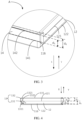
FIG. 1 is a front view of an electrochemical device according to an embodiment of this application; -
FIG. 2 is a three-dimensional diagram of an electrochemical device according to an embodiment of this application; -
FIG. 3 is a close-up view of a part A shown inFIG. 2 ; and -
FIG. 4 is a bottom view of an electrochemical device according to an embodiment of this application. - List of reference numerals:
- 100. electrochemical device;
- 10. housing; 11. main body; 111. first lateral face; 112. second lateral face; 113. third lateral face; 114. fourth lateral face; 115. first surface; 116. second surface; 12. tail seal portion; 121. first seal edge; 122. second seal edge; 13. first connecting portion; 131. first part; 1311. first edge; 132. second part; 1321. second edge; 1322. third edge; 14. first side seal portion; 141. third seal edge; 142. fourth seal edge; 15. second connecting portion; 16. first side seal portion; 17. top seal portion; 20. tab;
- X. first direction; Y second direction.
- For ease of understanding this application, the following describes this application in more detail with reference to drawings and specific embodiments. It is hereby noted that an element referred to herein as being "fixed to" another element may be directly disposed on the other element, or may be fixed to the other element with one or more elements in between. An element referred to herein as "connected to" another element may be connected to the other element directly or with one or more elements in between. The terms "vertical", "horizontal", "left", "right", and other similar expressions used herein are merely for ease of description.
- Unless otherwise defined, all technical and scientific terms used herein bear the same meanings as what is normally understood by a person skilled in the technical field of this application. The terms used in the specification of this application are merely intended to describe specific embodiments but not to limit this application. The term "and/or" used herein is intended to include any and all combinations of one or more relevant items recited.
- Referring to
FIG. 1 and FIG. 2 , an embodiment of this application provides anelectrochemical device 100. Theelectrochemical device 100 includes ahousing 10, an electrode assembly (not shown in the drawing), and atab 20. The electrode assembly is accommodated in thehousing 10. One end of thetab 20 is connected to the electrode assembly, and another end of thetab 20 extends out from themain body 11, and extends to the outside of thehousing 10. - For the
housing 10, referring toFIG. 2 to FIG. 4 , thehousing 10 includes amain body 11, atail seal portion 12, a first connectingportion 13, and a firstside seal portion 14. The electrode assembly is accommodated in themain body 11. Themain body 11 includes a firstlateral face 111, a secondlateral face 112, a thirdlateral face 113, a fourthlateral face 114, afirst surface 115, and asecond surface 116. The firstlateral face 111 is disposed opposite to the secondlateral face 112, the thirdlateral face 113 is disposed opposite to the fourthlateral face 114. The thirdlateral face 113 and the fourthlateral face 114 are located between the secondlateral face 112 and the firstlateral face 111. Thefirst surface 115 is disposed opposite to thesecond surface 116. Thefirst surface 115 and thesecond surface 116 each are connected to the firstlateral face 111, the secondlateral face 112, the thirdlateral face 113, and the fourthlateral face 114. - The other end of the
tab 20 extends out from the firstlateral face 111 of themain body 11. Thetail seal portion 12 is connected to the secondlateral face 112 of themain body 11. The firstside seal portion 14 is connected to the thirdlateral face 113 of themain body 11. The firstside seal portion 14 is connected to thetail seal portion 12 by the first connectingportion 13. Thetail seal portion 12 is configured to be folded in a first direction X, and the firstside seal portion 14 is configured to be folded in a second direction Y, so that the first connectingportion 13 closely fits the secondlateral face 112 of themain body 11. The first direction X is perpendicular to a direction from the firstlateral face 111 to the secondlateral face 112, and the first direction X is opposite to the second direction Y. In other words, the bending direction of the firstside seal portion 14 is opposite to the bending direction of thetail seal portion 12. - For the
tail seal portion 12, referring toFIG. 3 and FIG. 4 , thetail seal portion 12 includes afirst seal edge 121 and asecond seal edge 122. Thefirst seal edge 121 is an end edge by which thetail seal portion 12 is concatenated to themain body 11. Thesecond seal edge 122 is disposed opposite to thefirst seal edge 121. In the first direction X, thesecond seal edge 122 is closer to thesecond surface 116 than thefirst seal edge 121. In other words, thesecond surface 116 is an end face of themain body 11, the end face being closest to thesecond seal edge 122 in the first direction X. Along a direction perpendicular to the first direction, the length of thefirst seal edge 121 is greater than the length of thesecond seal edge 122. Thetail seal portion 12 is trapezoidal in shape. - In some embodiments, along the first direction X, a distance between the
first seal edge 121 and thesecond seal edge 122 is d3, and a distance between thefirst seal edge 121 and thesecond surface 116 is d4, satisfying: d4 ≥ d3. In this way, thetail seal portion 12 is prevented from protruding beyond thesecond surface 116 of themain body 11 along the first direction X. In contrast to a scenario in which thetail seal portion 12 protrudes beyond thesecond surface 116 of themain body 11 along the first direction X, the prevention of thetail seal portion 12 from protruding beyond thesecond surface 116 of themain body 11 along the first direction X can reduce the area occupied by theelectrochemical device 100 and favorably increase the energy density. - For the first connecting
portion 13, referring toFIG. 4 , the first connectingportion 13 includes afirst part 131 and asecond part 132. Thefirst part 131 is an overlap part at which the first connectingportion 13 overlaps thetail seal portion 12. Thesecond part 132 is connected to thefirst part 131. The other end of thesecond part 132 is connected to the firstside seal portion 14. The cross-section of thefirst part 131 along the first direction X is triangular in shape. Specifically, thefirst part 131 includes afirst edge 1311. Thefirst edge 1311 is an end edge by which the first connectingportion 13 is connected to thetail seal portion 12. An angle between thefirst edge 1311 and thefirst seal edge 121 is α, and the angle α is less than 90°. In some embodiments, the angle α ranges from 30° to 60°. - The cross-section of the
second part 132 along the first direction X is rectangular in shape. Specifically, thesecond part 132 includes asecond edge 1321 and a third edge 1322 disposed opposite to each other. The third edge 1322 is an end edge by which thesecond part 132 is connected to thefirst part 131. In the second direction Y, thesecond edge 1321 is closer to thefirst surface 115 than the third edge 1322. In other words, thefirst surface 115 is an end face of themain body 11, the end face being closest to thesecond edge 1321 in the second direction Y. - In some embodiments, along the second direction Y, a distance between the
second edge 1321 and the third edge 1322 is d1, and a distance between the third edge 1322 and thefirst surface 115 is d2, satisfying: d2 ≥ d1. In this way, the first connectingportion 13 is prevented from protruding beyond thefirst surface 115 of themain body 11 along the second direction Y, thereby further reducing the area occupied by theelectrochemical device 100, and favorably increasing the energy density. - For the first
side seal portion 14, referring toFIG. 3 , the firstside seal portion 14 includes athird seal edge 141 and afourth seal edge 142 disposed opposite to each other. Thethird seal edge 141 is an end edge by which the firstside seal portion 14 is concatenated to themain body 11. The cross-section of the firstside seal portion 14 along the first direction X is rectangular in shape. - In some embodiments, along the second direction Y, a distance between the
third seal edge 141 and thefourth seal edge 142 is d5, and a distance between thethird seal edge 141 and thefirst surface 115 is d6, satisfying: d6 ≥ d5. In this way, the firstside seal portion 14 is prevented from protruding beyond thefirst surface 115 of themain body 11 along the second direction Y, thereby further reducing the area occupied by the electrochemical device, and favorably increasing the energy density. - It is hereby noted that even though the shape of the
electrochemical device 100 in the drawing of the above embodiment is a regular hexahedron, this application is not limited to the illustrated example. In other embodiments of this application, theelectrochemical device 100 and thehousing 10 may be other shapes instead, as long as thetail seal portion 12, the first connectingportion 13, and the firstside seal portion 14 thereof can be folded to fit onto themain body 11 during bending. For example, when the main body is in the shape of another polyhedron, the energy density can still be increased as long as the following conditions are met: the tail seal portion and the first side seal portion are connected to two adjacent surfaces of the main body respectively, and the tail seal portion and the first side seal portion are folded in opposite directions to fit onto the two adjacent surfaces respectively, and the first connecting portion connected to the tail seal portion and the first side seal portion is folded to closely fit any one of the two adjacent surfaces. - Still referring to
FIG. 2 , thehousing 10 further includes a second connectingportion 15 and a secondside seal portion 16. The secondside seal portion 16 is connected to the fourthlateral face 114 of themain body 11. The secondside seal portion 16 is connected to thetail seal portion 12 by the second connectingportion 15. The secondside seal portion 16 is configured to be folded in the second direction Y, so that the second connectingportion 15 closely fits the secondlateral face 112 of themain body 11, thereby reducing the area occupied by theelectrochemical device 100 and favorably increasing the energy density. - Understandably, the structure of the second connecting
portion 15 is similar to that of the first connectingportion 13, and is not described in detail here. - For the above electrode assembly, the electrode assembly includes a first electrode plate (not shown in the drawing), a second electrode plate (not shown in the drawing), and a separator (not shown in the drawing). The separator is located between the first electrode plate and the second electrode plate. The first electrode plate, the separator, and the second electrode plate are stacked and wound.
- For the
tab 20, referring toFIG. 2 again, there are twotabs 20. Thehousing 10 further includes atop seal portion 17. Thetop seal portion 17 is connected to the firstlateral face 111 of themain body 11. Thetop seal portion 17 and thetail seal portion 12 are located at two opposite ends of themain body 11 respectively. Of the twotabs 20, one end of one tab is connected to the first electrode plate, and one end of the other tab is connected to the second electrode plate. Of the twotabs 20, the other end of one tab and the other end of the other tab pass out of thehousing 10 through the firstlateral face 111 of themain body 11 and thetop seal portion 17. - The
electrochemical device 100 provided in an embodiment of this application includes an electrode assembly, atab 20, and ahousing 10. Thehousing 10 includes amain body 11. The electrode assembly is accommodated in themain body 11. One end of thetab 20 is connected to the electrode assembly, and another end of thetab 20 extends out from a firstlateral face 111 of themain body 11. Specifically, thehousing 10 further includes atail seal portion 12, a first connectingportion 13, and a firstside seal portion 14. Thetail seal portion 12 is connected to a secondlateral face 112 of themain body 11. The firstside seal portion 14 is connected to a thirdlateral face 113 of themain body 11. The firstlateral face 111 and the secondlateral face 112 are disposed opposite to each other. The thirdlateral face 113 is located between the secondlateral face 112 and the firstlateral face 111. The firstside seal portion 14 is connected to thetail seal portion 12 by the first connectingportion 13. Thetail seal portion 12 is configured to be folded in a first direction X, and the firstside seal portion 14 is configured to be folded in a second direction Y, so that the first connectingportion 13 closely fits the secondlateral face 112 of themain body 11. The first direction X is perpendicular to a direction from the firstlateral face 111 to the secondlateral face 112, and the first direction X is opposite to the second direction Y. In this way, themain body 11 of thehousing 10 can accommodate the electrode assembly. Thetail seal portion 12, the first connectingportion 13, and the firstside seal portion 14 of thehousing 10 can fit onto themain body 11 by folding, thereby reducing the area occupied by theelectrochemical device 100. When being mounted, other components do not need to avoid thehousing 10, thereby increasing the energy density. - An embodiment of this application further provides a battery module. The battery module includes the
electrochemical device 100. The structure of theelectrochemical device 100 may be learned by referring to the above embodiment, details of which are omitted here. - An embodiment of this application further provides an electronic device. The electronic device includes the
electrochemical device 100 or the battery module. The structure of theelectrochemical device 100 or the battery module may be learned by referring to the above embodiment, details of which are omitted here. In this embodiment, the electronic device is a mobile phone. Understandably, in other embodiments of this application, the electronic device may be a tablet computer, a computer, an unmanned aerial vehicle, or another electrical device that needs to be powered by electricity. - It is hereby noted that although preferred embodiments of this application have been given in the specification and drawings of this application, this application may be implemented in many different forms, without being limited to the embodiments described herein. The embodiments are not intended to limit the content of this application, but merely to facilitate thorough and comprehensive understanding of the content disclosed herein. In addition, all kinds of embodiments that are not enumerated above but are derived by further combination of the foregoing technical features still fall within the scope covered by this application. Further, all improvements and variations, which may be made by a person of ordinary skill in the art based on the foregoing description, still fall within the protection scope of the claims appended hereto.
Claims (11)
- An electrochemical device, comprising an electrode assembly, a tab, and a housing, wherein the housing comprises a main body, the electrode assembly is accommodated in the housing, one end of the tab is connected to the electrode assembly, and another end of the tab extends out from a first lateral face of the main body, characterized in that:the housing comprises a tail seal portion, a first connecting portion, and a first side seal portion; the tail seal portion is connected to a second lateral face of the main body; the first side seal portion is connected to a third lateral face of the main body; the first lateral face and the second lateral face are disposed opposite to each other; the third lateral face is located between the second lateral face and the first lateral face; and the first side seal portion is connected to the tail seal portion by the first connecting portion; andthe tail seal portion is configured to be folded in a first direction, and the first side seal portion is configured to be folded in a second direction, so that the first connecting portion closely fits the second lateral face of the main body, wherein the first direction is perpendicular to a direction from the first lateral face to the second lateral face, and the first direction is opposite to the second direction.
- The electrochemical device according to claim 1, characterized in that the first connecting portion comprises a first part, the first part is an overlap part at which the first connecting portion overlaps the tail seal portion, the first part comprises a first edge, the first edge is an end edge by which the first connecting portion is connected to the tail seal portion, the tail seal portion comprises a first seal edge, the first seal edge is an end edge by which the tail seal portion is concatenated to the main body, an angle between the first edge and the first seal edge is α, and the angle α is less than 90°.
- The electrochemical device according to claim 2, characterized in that the angle α ranges from 30° to 60°.
- The electrochemical device according to claim 2, characterized in that the first connecting portion further comprises a second part, the second part is connected to the first part, the second part comprises a second edge and a third edge disposed opposite to each other, and the third edge is an end edge by which the second part is connected to the first part; the main body comprises a first surface, and the first surface is an end face of the main body, the end face being closest to the second edge in the second direction; and
along the second direction, a distance between the second edge and the third edge is d1, and a distance between the third edge and the first surface is d2, satisfying: d2 ≥ d1. - The electrochemical device according to claim 2, characterized in that the tail seal portion further comprises a second seal edge, the second seal edge and the first seal edge are two edges disposed opposite to each other, the main body further comprises a second surface, and the second surface is an end face of the main body, the end face being closest to the second seal edge in the first direction; and
along the first direction, a distance between the first seal edge and the second seal edge is d3, and a distance between the first seal edge and the second surface is d4, satisfying: d4 ≥ d3. - The electrochemical device according to claim 4, characterized in that the first side seal portion comprises a third seal edge and a fourth seal edge disposed opposite to each other, and the third seal edge is an end edge by which the first side seal portion is concatenated to the main body; and
along the second direction, a distance between the third seal edge and the fourth seal edge is d5, and a distance between the third seal edge and the first surface is d6, satisfying: d6 ≥ d5. - The electrochemical device according to claim 1, characterized in thatthe main body comprises a fourth lateral face, and the fourth lateral face is disposed opposite to the third lateral face;the housing further comprises a second connecting portion and a second side seal portion, the second side seal portion is connected to the fourth lateral face of the main body, and the second side seal portion is connected to the tail seal portion by the second connecting portion; andthe second side seal portion is configured to be folded in the second direction, so that the second connecting portion closely fits the second lateral face of the main body.
- The electrochemical device according to claim 1, characterized in that the housing further comprises a top seal portion, the top seal portion is connected to the first lateral face of the main body, and the top seal portion and the tail seal portion are located at two opposite ends of the main body respectively; and
one end of the tab is connected to the electrode assembly, and another end of the tab passes out of the housing from the top seal portion. - The electrochemical device according to claim 1, characterized in that the electrode assembly comprises a first electrode plate, a second electrode plate, and a separator; the separator is located between the first electrode plate and the second electrode plate; and the first electrode plate, the separator, and the second electrode plate are stacked and wound.
- A battery module, characterized in that the battery module comprises the electrochemical device according to any one of claims 1 to 9.
- An electronic device, characterized in that the electronic device comprises the electrochemical device according to any one of claims 1 to 9 or the battery module according to claim 10.
Applications Claiming Priority (1)
| Application Number | Priority Date | Filing Date | Title |
|---|---|---|---|
| PCT/CN2022/085866 WO2023193247A1 (en) | 2022-04-08 | 2022-04-08 | Electrochemical apparatus, battery module and electronic device |
Publications (2)
| Publication Number | Publication Date |
|---|---|
| EP4507073A1 true EP4507073A1 (en) | 2025-02-12 |
| EP4507073A4 EP4507073A4 (en) | 2025-08-06 |
Family
ID=86356556
Family Applications (1)
| Application Number | Title | Priority Date | Filing Date |
|---|---|---|---|
| EP22936185.2A Pending EP4507073A4 (en) | 2022-04-08 | 2022-04-08 | ELECTROCHEMICAL DEVICE, BATTERY MODULE AND ELECTRONIC DEVICE |
Country Status (4)
| Country | Link |
|---|---|
| US (1) | US20250038322A1 (en) |
| EP (1) | EP4507073A4 (en) |
| CN (1) | CN116157955B (en) |
| WO (1) | WO2023193247A1 (en) |
Families Citing this family (1)
| Publication number | Priority date | Publication date | Assignee | Title |
|---|---|---|---|---|
| CN118610541A (en) * | 2024-06-06 | 2024-09-06 | 深圳市豪鹏科技股份有限公司 | Packaging method of soft pack battery and soft pack battery |
Family Cites Families (10)
| Publication number | Priority date | Publication date | Assignee | Title |
|---|---|---|---|---|
| JP3527858B2 (en) * | 1999-01-04 | 2004-05-17 | 三菱電機株式会社 | Battery |
| JP4819512B2 (en) * | 2006-01-24 | 2011-11-24 | Necエナジーデバイス株式会社 | Laminated battery |
| KR101595611B1 (en) * | 2013-03-22 | 2016-02-18 | 주식회사 엘지화학 | a secondary battery for improving energy degree |
| JP7109231B2 (en) * | 2018-03-30 | 2022-07-29 | 三洋電機株式会社 | Prismatic non-aqueous electrolyte secondary battery and manufacturing method thereof |
| JP2020149935A (en) * | 2019-03-15 | 2020-09-17 | 株式会社日立製作所 | Battery module |
| WO2021110179A1 (en) * | 2019-12-06 | 2021-06-10 | 东莞新能德科技有限公司 | Battery, battery assembly, battery pack and electronic apparatus |
| CN214672783U (en) * | 2021-03-25 | 2021-11-09 | 东莞新能德科技有限公司 | Batteries and Electrical Equipment |
| CN215680800U (en) * | 2021-05-19 | 2022-01-28 | 东莞锂威能源科技有限公司 | A soft pack battery with a folded edge |
| CN113437443B (en) * | 2021-06-21 | 2023-06-20 | 东莞新能安科技有限公司 | Electrochemical devices and electronic devices |
| CN114188597B (en) * | 2021-11-25 | 2024-11-15 | 宁德新能源科技有限公司 | Electrochemical devices, battery modules and electrical equipment |
-
2022
- 2022-04-08 EP EP22936185.2A patent/EP4507073A4/en active Pending
- 2022-04-08 CN CN202280006036.3A patent/CN116157955B/en active Active
- 2022-04-08 WO PCT/CN2022/085866 patent/WO2023193247A1/en not_active Ceased
-
2024
- 2024-10-08 US US18/908,904 patent/US20250038322A1/en active Pending
Also Published As
| Publication number | Publication date |
|---|---|
| WO2023193247A1 (en) | 2023-10-12 |
| CN116157955A (en) | 2023-05-23 |
| US20250038322A1 (en) | 2025-01-30 |
| CN116157955B (en) | 2025-01-21 |
| EP4507073A4 (en) | 2025-08-06 |
Similar Documents
| Publication | Publication Date | Title |
|---|---|---|
| EP4207477A1 (en) | Electrochemical device and electronic device | |
| WO2021110179A1 (en) | Battery, battery assembly, battery pack and electronic apparatus | |
| EP4080599A1 (en) | Electrode assembly and battery | |
| CN212011033U (en) | Battery and electronic device having the same | |
| EP4258431A1 (en) | Current collecting member, cell and electronic device | |
| US20230327248A1 (en) | Electrochemical device and electrical device | |
| EP4604280A1 (en) | Packaging bag, battery cell, and electrical device | |
| EP3171426B1 (en) | Rechargeable battery | |
| US20250038322A1 (en) | Electrochemical device, battery module, and electronic device | |
| WO2025251862A1 (en) | Battery cell assembly, battery, and electric device | |
| US20250046966A1 (en) | Battery and electronic device | |
| CN217589192U (en) | Battery and electronic device | |
| WO2025171771A1 (en) | Battery cell and electric device | |
| EP4318749A1 (en) | Battery cell and electrical device | |
| US12374743B2 (en) | Packaging structure and battery core using the same | |
| US20220223918A1 (en) | Secondary battery and battery module | |
| CN114747070B (en) | Batteries, battery components, battery packs and electronic devices | |
| CN212625746U (en) | Battery, battery pack, and electronic device | |
| CN114361559A (en) | Battery with a battery cell | |
| CN212625794U (en) | Battery and electronic device with same | |
| CN214672783U (en) | Batteries and Electrical Equipment | |
| CN222355197U (en) | Battery components and electrical equipment | |
| CN211088352U (en) | Package structure and battery cell using the package structure | |
| EP4131597A1 (en) | Packaging structure and electrochemical device applying the packaging structure | |
| CN209843753U (en) | Laminated battery |
Legal Events
| Date | Code | Title | Description |
|---|---|---|---|
| STAA | Information on the status of an ep patent application or granted ep patent |
Free format text: STATUS: THE INTERNATIONAL PUBLICATION HAS BEEN MADE |
|
| PUAI | Public reference made under article 153(3) epc to a published international application that has entered the european phase |
Free format text: ORIGINAL CODE: 0009012 |
|
| STAA | Information on the status of an ep patent application or granted ep patent |
Free format text: STATUS: REQUEST FOR EXAMINATION WAS MADE |
|
| 17P | Request for examination filed |
Effective date: 20241108 |
|
| AK | Designated contracting states |
Kind code of ref document: A1 Designated state(s): AL AT BE BG CH CY CZ DE DK EE ES FI FR GB GR HR HU IE IS IT LI LT LU LV MC MK MT NL NO PL PT RO RS SE SI SK SM TR |
|
| DAV | Request for validation of the european patent (deleted) | ||
| DAX | Request for extension of the european patent (deleted) | ||
| A4 | Supplementary search report drawn up and despatched |
Effective date: 20250708 |
|
| RIC1 | Information provided on ipc code assigned before grant |
Ipc: H01M 50/10 20210101AFI20250702BHEP Ipc: H01M 50/186 20210101ALI20250702BHEP Ipc: H01M 50/103 20210101ALI20250702BHEP |