EP4507059A1 - Battery module and preparation method therefor, and battery pack and electric apparatus - Google Patents
Battery module and preparation method therefor, and battery pack and electric apparatus Download PDFInfo
- Publication number
- EP4507059A1 EP4507059A1 EP22961772.5A EP22961772A EP4507059A1 EP 4507059 A1 EP4507059 A1 EP 4507059A1 EP 22961772 A EP22961772 A EP 22961772A EP 4507059 A1 EP4507059 A1 EP 4507059A1
- Authority
- EP
- European Patent Office
- Prior art keywords
- solid
- current collector
- positive electrode
- negative electrode
- battery module
- Prior art date
- Legal status (The legal status is an assumption and is not a legal conclusion. Google has not performed a legal analysis and makes no representation as to the accuracy of the status listed.)
- Pending
Links
Images


Classifications
-
- H—ELECTRICITY
- H01—ELECTRIC ELEMENTS
- H01M—PROCESSES OR MEANS, e.g. BATTERIES, FOR THE DIRECT CONVERSION OF CHEMICAL ENERGY INTO ELECTRICAL ENERGY
- H01M4/00—Electrodes
- H01M4/02—Electrodes composed of, or comprising, active material
- H01M4/64—Carriers or collectors
- H01M4/66—Selection of materials
- H01M4/665—Composites
- H01M4/667—Composites in the form of layers, e.g. coatings
-
- H—ELECTRICITY
- H01—ELECTRIC ELEMENTS
- H01M—PROCESSES OR MEANS, e.g. BATTERIES, FOR THE DIRECT CONVERSION OF CHEMICAL ENERGY INTO ELECTRICAL ENERGY
- H01M50/00—Constructional details or processes of manufacture of the non-active parts of electrochemical cells other than fuel cells, e.g. hybrid cells
- H01M50/50—Current conducting connections for cells or batteries
- H01M50/531—Electrode connections inside a battery casing
-
- H—ELECTRICITY
- H01—ELECTRIC ELEMENTS
- H01M—PROCESSES OR MEANS, e.g. BATTERIES, FOR THE DIRECT CONVERSION OF CHEMICAL ENERGY INTO ELECTRICAL ENERGY
- H01M10/00—Secondary cells; Manufacture thereof
- H01M10/05—Accumulators with non-aqueous electrolyte
- H01M10/056—Accumulators with non-aqueous electrolyte characterised by the materials used as electrolytes, e.g. mixed inorganic/organic electrolytes
- H01M10/0561—Accumulators with non-aqueous electrolyte characterised by the materials used as electrolytes, e.g. mixed inorganic/organic electrolytes the electrolyte being constituted of inorganic materials only
- H01M10/0562—Solid materials
-
- H—ELECTRICITY
- H01—ELECTRIC ELEMENTS
- H01M—PROCESSES OR MEANS, e.g. BATTERIES, FOR THE DIRECT CONVERSION OF CHEMICAL ENERGY INTO ELECTRICAL ENERGY
- H01M10/00—Secondary cells; Manufacture thereof
- H01M10/05—Accumulators with non-aqueous electrolyte
- H01M10/056—Accumulators with non-aqueous electrolyte characterised by the materials used as electrolytes, e.g. mixed inorganic/organic electrolytes
- H01M10/0564—Accumulators with non-aqueous electrolyte characterised by the materials used as electrolytes, e.g. mixed inorganic/organic electrolytes the electrolyte being constituted of organic materials only
- H01M10/0565—Polymeric materials, e.g. gel-type or solid-type
-
- H—ELECTRICITY
- H01—ELECTRIC ELEMENTS
- H01M—PROCESSES OR MEANS, e.g. BATTERIES, FOR THE DIRECT CONVERSION OF CHEMICAL ENERGY INTO ELECTRICAL ENERGY
- H01M10/00—Secondary cells; Manufacture thereof
- H01M10/05—Accumulators with non-aqueous electrolyte
- H01M10/058—Construction or manufacture
- H01M10/0585—Construction or manufacture of accumulators having only flat construction elements, i.e. flat positive electrodes, flat negative electrodes and flat separators
-
- H—ELECTRICITY
- H01—ELECTRIC ELEMENTS
- H01M—PROCESSES OR MEANS, e.g. BATTERIES, FOR THE DIRECT CONVERSION OF CHEMICAL ENERGY INTO ELECTRICAL ENERGY
- H01M4/00—Electrodes
- H01M4/02—Electrodes composed of, or comprising, active material
- H01M4/62—Selection of inactive substances as ingredients for active masses, e.g. binders, fillers
-
- H—ELECTRICITY
- H01—ELECTRIC ELEMENTS
- H01M—PROCESSES OR MEANS, e.g. BATTERIES, FOR THE DIRECT CONVERSION OF CHEMICAL ENERGY INTO ELECTRICAL ENERGY
- H01M4/00—Electrodes
- H01M4/02—Electrodes composed of, or comprising, active material
- H01M4/62—Selection of inactive substances as ingredients for active masses, e.g. binders, fillers
- H01M4/621—Binders
- H01M4/622—Binders being polymers
-
- H—ELECTRICITY
- H01—ELECTRIC ELEMENTS
- H01M—PROCESSES OR MEANS, e.g. BATTERIES, FOR THE DIRECT CONVERSION OF CHEMICAL ENERGY INTO ELECTRICAL ENERGY
- H01M4/00—Electrodes
- H01M4/02—Electrodes composed of, or comprising, active material
- H01M4/62—Selection of inactive substances as ingredients for active masses, e.g. binders, fillers
- H01M4/621—Binders
- H01M4/622—Binders being polymers
- H01M4/623—Binders being polymers fluorinated polymers
-
- H—ELECTRICITY
- H01—ELECTRIC ELEMENTS
- H01M—PROCESSES OR MEANS, e.g. BATTERIES, FOR THE DIRECT CONVERSION OF CHEMICAL ENERGY INTO ELECTRICAL ENERGY
- H01M4/00—Electrodes
- H01M4/02—Electrodes composed of, or comprising, active material
- H01M4/62—Selection of inactive substances as ingredients for active masses, e.g. binders, fillers
- H01M4/624—Electric conductive fillers
- H01M4/625—Carbon or graphite
-
- H—ELECTRICITY
- H01—ELECTRIC ELEMENTS
- H01M—PROCESSES OR MEANS, e.g. BATTERIES, FOR THE DIRECT CONVERSION OF CHEMICAL ENERGY INTO ELECTRICAL ENERGY
- H01M4/00—Electrodes
- H01M4/02—Electrodes composed of, or comprising, active material
- H01M4/64—Carriers or collectors
- H01M4/66—Selection of materials
- H01M4/663—Selection of materials containing carbon or carbonaceous materials as conductive part, e.g. graphite, carbon fibres
-
- H—ELECTRICITY
- H01—ELECTRIC ELEMENTS
- H01M—PROCESSES OR MEANS, e.g. BATTERIES, FOR THE DIRECT CONVERSION OF CHEMICAL ENERGY INTO ELECTRICAL ENERGY
- H01M4/00—Electrodes
- H01M4/02—Electrodes composed of, or comprising, active material
- H01M2004/021—Physical characteristics, e.g. porosity, surface area
-
- H—ELECTRICITY
- H01—ELECTRIC ELEMENTS
- H01M—PROCESSES OR MEANS, e.g. BATTERIES, FOR THE DIRECT CONVERSION OF CHEMICAL ENERGY INTO ELECTRICAL ENERGY
- H01M2300/00—Electrolytes
- H01M2300/0017—Non-aqueous electrolytes
- H01M2300/0065—Solid electrolytes
- H01M2300/0068—Solid electrolytes inorganic
-
- H—ELECTRICITY
- H01—ELECTRIC ELEMENTS
- H01M—PROCESSES OR MEANS, e.g. BATTERIES, FOR THE DIRECT CONVERSION OF CHEMICAL ENERGY INTO ELECTRICAL ENERGY
- H01M2300/00—Electrolytes
- H01M2300/0017—Non-aqueous electrolytes
- H01M2300/0065—Solid electrolytes
- H01M2300/0068—Solid electrolytes inorganic
- H01M2300/0071—Oxides
-
- H—ELECTRICITY
- H01—ELECTRIC ELEMENTS
- H01M—PROCESSES OR MEANS, e.g. BATTERIES, FOR THE DIRECT CONVERSION OF CHEMICAL ENERGY INTO ELECTRICAL ENERGY
- H01M2300/00—Electrolytes
- H01M2300/0017—Non-aqueous electrolytes
- H01M2300/0065—Solid electrolytes
- H01M2300/0082—Organic polymers
-
- Y—GENERAL TAGGING OF NEW TECHNOLOGICAL DEVELOPMENTS; GENERAL TAGGING OF CROSS-SECTIONAL TECHNOLOGIES SPANNING OVER SEVERAL SECTIONS OF THE IPC; TECHNICAL SUBJECTS COVERED BY FORMER USPC CROSS-REFERENCE ART COLLECTIONS [XRACs] AND DIGESTS
- Y02—TECHNOLOGIES OR APPLICATIONS FOR MITIGATION OR ADAPTATION AGAINST CLIMATE CHANGE
- Y02E—REDUCTION OF GREENHOUSE GAS [GHG] EMISSIONS, RELATED TO ENERGY GENERATION, TRANSMISSION OR DISTRIBUTION
- Y02E60/00—Enabling technologies; Technologies with a potential or indirect contribution to GHG emissions mitigation
- Y02E60/10—Energy storage using batteries
Definitions
- the present application relates to the technical field of secondary batteries, and in particular to a battery module and a method for preparing the same, a battery pack and an electrical apparatus.
- secondary batteries are widely used in energy storage power systems such as water power, thermal power, wind power and solar power stations, as well as power tools, electric bicycles, electric motorcycles, electric vehicles, military equipment, aerospace and other fields.
- a battery cell is first prepared, then a plurality of battery cells are connected in series and parallel to form a battery module, and then the plurality of battery modules are assembled into the battery pack.
- the manufacturing of positive and negative electrode plates of a battery cell is generally formed by coating positive and negative electrode materials on current collectors of a metal foil material such as copper foil and aluminum foil.
- the use of current collectors such as the copper foil and the aluminum foil will increase the cost of a battery; and the preparation process of coating first and then assembling is cumbersome.
- the present application is made in view of the aforementioned problems, and one of its objectives is to provide a battery module that does not require to dispose current collectors of a metal foil material in positive and negative electrode plates, which can reduce the production cost and can simplify the preparation process.
- a first aspect of the present application provides a battery module, including a positive electrode current collector, a negative electrode current collector, and a plurality of solid-state battery cells.
- the plurality of solid-state battery cells are stacked between the positive electrode current collector and the negative electrode current collector. Adjacent ones of the solid-state battery cells are electrically connected through a current collector coating layer.
- the solid-state battery cells at both ends are electrically connected to the positive electrode current collector and the negative electrode current collector respectively.
- the current collector coating layer includes a conductive material.
- the conductive material includes one or more of conductive carbon black, a carbon nanotube, graphene and a conductive polymer.
- the weight percentage of the conductive material in the current collector coating layer is 10%-100%.
- the current collector coating layer includes a first binder.
- the first binder includes one or more of polyvinylidene fluoride, polytetrafluoroethylene, a vinylidene fluoride-tetrafluoroethylene-propylene terpolymer, a vinylidene fluoride-hexafluoropropylene-tetrafluoroethylene terpolymer, a tetrafluoroethylene-hexafluoropropylene copolymer and a fluorine-containing acrylate resin.
- the weight percentage of the first binder in the current collector coating layer is ⁇ 50%.
- the current collector coating layer includes a first thickener.
- the first thickener includes one or more of a carboxymethyl cellulose salt, a hydroxyethyl cellulose salt and a hydroxypropylmethyl cellulose salt.
- the weight percentage of the first thickener in the current collector coating layer is ⁇ 40%.
- the current collector coating layer has a thickness of 1 ⁇ m-1,000 ⁇ m.
- the current collector coating layer has a thickness of 4 ⁇ m-100 ⁇ m.
- the current collector coating layer has a thickness of 6 ⁇ m-20 ⁇ m.
- the solid-state battery cell includes a positive electrode layer, a solid-state electrolyte layer and a negative electrode layer.
- the solid-state electrolyte layer is located between the positive electrode layer and the negative electrode layer.
- the positive electrode layer includes a positive electrode active material.
- the positive electrode active material includes one or more of an oxide with a layered structure, a phosphate with an olivine structure, a compound with a spinel structure, an inorganic complex, sulfur and a sulfide.
- the weight percentage of the positive electrode active material in the positive electrode coating is 50%-99.99%.
- the positive electrode layer includes a first conductive agent.
- the first conductive agent includes one or more of carbon materials with good conductivity, such as conductive carbon black, acetylene black, a conductive carbon fiber, a carbon nanotube and graphene powder.
- the weight percentage of the first conductive agent in the positive electrode layer is ⁇ 50%.
- the positive electrode layer includes a first solid-state electrolyte.
- the first solid-state electrolyte includes one or more of an inorganic sulfide solid electrolyte, an inorganic oxide solid electrolyte, and an organic polymer solid electrolyte.
- the weight percentage of the first solid-state electrolyte in the positive electrode layer is ⁇ 50%.
- the positive electrode layer includes a second binder.
- the second binder includes one or more of polyvinylidene fluoride, polytetrafluoroethylene, a vinylidene fluoride-tetrafluoroethylene-propylene terpolymer, a vinylidene fluoride-hexafluoropropylene-tetrafluoroethylene terpolymer, a tetrafluoroethylene-hexafluoropropylene copolymer and a fluorine-containing acrylate resin.
- the weight percentage of the second binder in the positive electrode layer is ⁇ 50%.
- the positive electrode layer includes a second thickener.
- the second thickener includes one or more of a carboxymethyl cellulose salt, a hydroxyethyl cellulose salt and a hydroxypropylmethyl cellulose salt.
- the weight percentage of the second thickener in the positive electrode layer is ⁇ 50%.
- the negative electrode layer includes a negative electrode active material.
- the negative electrode active material includes one or more of lithium titanate, hard carbon, graphite, activated carbon, lithium foil, a silicon-based material, a tin-based material, an antimony-based material, a lead-based material, phosphorus and a phosphorus compound.
- the weight percentage of the negative electrode active material in the negative electrode layer is 50%-99.99%.
- the weight percentage of the second conductive agent in the negative electrode layer is ⁇ 50%.
- the negative electrode layer includes a second solid-state electrolyte.
- the second solid-state electrolyte includes one or more of an inorganic sulfide solid electrolyte, an inorganic oxide solid electrolyte, and an organic polymer solid electrolyte.
- the weight percentage of the second solid-state electrolyte in the negative electrode layer is ⁇ 50%.
- the negative electrode layer includes a third binder.
- the third binder includes one or more of styrene butadiene rubber, polyacrylic acid, sodium polyacrylate, polyacrylamide, polyvinyl alcohol, sodium alginate, polymethacrylic acid, and carboxymethyl chitosan.
- the weight percentage of the third binder in the negative electrode layer is ⁇ 50%.
- the solid-state electrolyte layer includes a solid-state electrolyte particle.
- the solid-state electrolyte particle includes one or more of an inorganic sulfide solid electrolyte, an inorganic oxide solid electrolyte, and an organic polymer solid electrolyte.
- the weight percentage of the solid-state electrolyte particle in the solid-state electrolyte layer is 50%-100%.
- the solid-state electrolyte layer includes a fourth binder.
- the fourth binder includes one or more of polyethylene oxide and a derivative thereof, polysiloxane and a derivative thereof, polyvinyl chloride and a derivative thereof, polycarbonate and a derivative thereof, polyacrylonitrile and a derivative thereof, polymethyl methacrylate and a derivative thereof, polyvinylidene fluoride and a derivative thereof, polytetrafluoroethylene and a derivative thereof, a vinylidene fluoride-tetrafluoroethylene-propylene terpolymer, a vinylidene fluoride-hexafluoropropylene-tetrafluoroethylene terpolymer, a tetrafluoroethylene-hexafluoropropylene copolymer, and a fluorine-containing acrylate resin.
- the weight percentage of the fourth binder in the solid-state electrolyte layer is ⁇ 50%.
- the solid-state electrolyte layer includes a third thickener.
- the third thickener includes one or more of a carboxymethyl cellulose salt, a hydroxyethyl cellulose salt and a hydroxypropylmethyl cellulose salt.
- the weight percentage of the third thickener in the solid-state electrolyte layer is ⁇ 40%.
- the battery module further includes a positive electrode lead-out tab and a negative electrode lead-out tab.
- the positive electrode lead-out tab is electrically connected to the positive electrode current collector, and the negative electrode lead-out tab is electrically connected to the negative electrode current collector.
- a second aspect of the present application provides a method for preparing a battery module, which includes forming a stacked structure with a plurality of solid-state battery cells between a positive electrode current collector and a negative electrode current collector, connecting adjacent ones of the solid-state battery cells through a current collector coating layer; and electrically connecting the solid-state battery cells located at both ends to the positive electrode current collector and the negative electrode current collector respectively.
- a third aspect of the present application provides a battery pack including the battery module according to the first aspect of the present application, or including a battery module obtained by the method for preparing a battery module according to the second aspect of the present application.
- a fourth aspect of the present application provides an electrical apparatus including the battery pack according to the third aspect of the present application.
- the current collector coating layer is disposed between the adjacent battery cells, so that there is no need to use a current collector of a metal foil material such as copper foil, aluminum foil and the like in the positive and negative electrode plates of the battery cells any more, which greatly reduces the use amount of the current collector of a metal foil material and reduces the production cost of the battery module; moreover, the battery module does not need to adopt a traditional manner of first coating the positive and negative electrode materials onto the current collectors to form battery cells, and then assembling to form a battery module, but instead adopts a manner of coating layer-by-layer to form coating layers, which simplifies the process flow of preparing the battery module.
- a metal foil material such as copper foil, aluminum foil and the like
- a “range” disclosed in the present application is defined in the form of a lower limit and an upper limit, with a given range being defined by the selection of a lower limit and an upper limit, and the selected lower and upper limits defining the boundaries of the particular range.
- a range defined in this manner may be inclusive or exclusive of end values, and may be arbitrarily combined, that is, any lower limit may be combined with any upper limit to form a range. For example, if ranges of 60-120 and 80-110 are listed for a particular parameter, it is understood that ranges of 60-110 and 80-120 are also contemplated.
- the numerical range "a-b" represents an abbreviated representation of any combination of real numbers between a and b, where both a and b are real numbers.
- the numerical range "0-5" means that all real numbers between "0-5" have been listed herein, and "0-5" is just an abbreviated representation of the combination of these numerical values.
- a certain parameter is an integer of ⁇ 2, it is equivalent to disclosing that the parameter is, for example, an integer of 2, 3, 4, 5, 6, 7, 8, 9, 10, 11, 12, etc.
- the method includes steps (a) and (b), meaning that the method may include steps (a) and (b) performed sequentially, or may include steps (b) and (a) performed sequentially.
- the reference to the method may further include step (c), meaning that step (c) may be added to the method in any order.
- the method may include steps (a), (b) and (c), or may further include steps (a), (c) and (b), or may further include steps (c), (a) and (b), and the like.
- a first aspect of the present application provides a battery module 1.
- the battery module 1 includes a positive electrode current collector 11, a negative electrode current collector 12, and a plurality of solid-state battery cells 13.
- the plurality of solid-state battery cells 13 are stacked between the positive electrode current collector 11 and the negative electrode current collector 12. Adjacent ones of the solid-state battery cells 13 are electrically connected through a current collector coating layer 14.
- the solid-state battery cells 13 at both ends are electrically connected to the positive electrode current collector 11 and the negative electrode current collector 12 respectively.
- the current collector coating layer 14 includes a conductive material.
- the conductive material includes one or more of conductive carbon black, a carbon nanotube, graphene and a conductive polymer.
- the conductive material in the current collector coating layer 14 includes one or more of conductive carbon black, a carbon nanotube, graphene and a conductive polymer, which can make the current collector coating layer 14 have good electronic conductivity and not have an ability of conducting lithium ions and sodium ions. That is, the formed current collector coating layer 14 can conduct electrons but not the lithium ions and sodium ions, and can function as a current collector of a metal foil material.
- the current collector coating layer 14 may further include a first thickener.
- the first thickener is sodium carboxymethyl cellulose (CMC-Na).
- the weight percentage of the conductive material is 10%-100%
- the weight percentage of the first binder is ⁇ 50%
- the weight percentage of the first thickener is ⁇ 40%.
- the weight percentage of the conductive material in the current collector coating layer 14 can be, but is not limited to 10%, 20%, 30%, 40%, 50%, 60%, 70%, 80%, 90%, and 100%; the weight percentage of the first binder in the current collector coating layer 14 can be, but is not limited to 0%, 10%, 20%, 30%, 40%, and 50%; and the weight percentage of the first thickener in the current collector coating layer 14 can be, but is not limited to 0%, 10%, 20%, 30%, and 40%. That is, the current collector coating layer 14 may be all conductive materials, may be a conductive material and partial of the first binder or the first thickener, or may also contain a conductive material, the first binder and the first thickener agent at the same time.
- the current collector coating layer 14 has a thickness of 1 ⁇ m-1,000 ⁇ m.
- the thickness of the current collector coating layer 14 can be, but is not limited to 1 ⁇ m, 10 ⁇ m, 100 ⁇ m, 200 ⁇ m, 300 ⁇ m, 400 ⁇ m, 500 ⁇ m, 600 ⁇ m, 700 ⁇ m, 800 ⁇ m, 900 ⁇ m, and 1,000 ⁇ m.
- the specific thickness of the current collector coating layer 14 can be set according to actual needs.
- the solid-state battery cell 13 includes a positive electrode layer 131, a solid-state electrolyte layer 132 and a negative electrode layer 133.
- the solid-state electrolyte layer 132 is located between the positive electrode layer 131 and the negative electrode layer 133. Therefore, in the present application, the positive electrode layer 131, the solid-state electrolyte layer 132 and the negative electrode layer 133 constituting the solid-state battery cell 13 can each be in the form of a coating layer. That is, the positive electrode layer 131, the solid-state electrolyte layer 132 and the negative electrode layer 133 are combined together by coating to form the solid-state battery cell 13.
- a current collector composed of metal foil does not need to be disposed in the solid-state battery cell 13. That is, it is not necessary to coat a positive electrode slurry onto the foil material of the positive electrode current collector to form a positive electrode plate, and it is not necessary to coat a negative electrode slurry onto the foil material of the negative electrode current collector to form the negative electrode plate. It is beneficial to reduce the production cost of the battery module 1 and simplify the production process.
- the positive electrode layer 131 includes a positive electrode active material.
- the positive electrode active material includes one or more of an oxide with a layered structure, a phosphate with an olivine structure, a compound with a spinel structure, an inorganic complex, sulfur and a sulfide.
- the positive electrode layer 131 further includes a first conductive agent.
- the first conductive agent includes one or more of carbon materials with good conductivity, such as conductive carbon black, acetylene black, a conductive carbon fiber, a carbon nanotube and graphene powder.
- the positive electrode layer 131 further includes a first solid-state electrolyte.
- the first solid-state electrolyte includes one or more of an inorganic sulfide solid electrolyte, an inorganic oxide solid electrolyte, and an organic polymer solid electrolyte.
- the positive electrode layer 131 further includes a second binder.
- the second binder may include one or more of polyvinylidene fluoride (PVDF), polytetrafluoroethylene (PTFE), a vinylidene fluoride-tetrafluoroethylene-propylene terpolymer, a vinylidene fluoride-hexafluoropropylene-tetrafluoroethylene terpolymer, a tetrafluoroethylene-hexafluoropropylene copolymer and a fluorine-containing acrylate resin.
- PVDF polyvinylidene fluoride
- PTFE polytetrafluoroethylene
- the positive electrode layer 131 further includes a second thickener.
- the second thickener is sodium carboxymethyl cellulose.
- the weight percentage of the positive electrode active material is 50%-99.99%
- the weight percentage of the first conductive agent is ⁇ 50%
- the weight percentage of the first solid-state electrolyte is ⁇ 50%
- the weight percentage of the second binder is ⁇ 50%
- the weight percentage of the second thickener is ⁇ 50%.
- the weight percentage of the positive electrode active material can be but is not limited to 50%, 60%, 70%, 80%, 90%, and 99.99%; the weight percentage of the first conductive agent can be but is not limited to 0%, 10%, 20%, 30%, 40%, and 50%; the weight percentage of the first solid-state electrolyte can be but is not limited to 0%, 10%, 20%, 30%, 40%, and 50%; the weight percentage of the second binder can be but is not limited to 0%, 10%, 20%, 30%, 40%, and 50%; and the weight percentage of the second thickener can be but is not limited to 0%, 10%, 20%, 30%, 40%, and 50%.
- the negative electrode layer 133 includes a negative electrode active material.
- the negative electrode active material includes one or more of lithium titanate, hard carbon, graphite, activated carbon, lithium foil, a silicon-based material, a tin-based material, an antimony-based material, a lead-based material, phosphorus and a phosphorus compound.
- the negative electrode layer 133 further includes a second conductive agent.
- the second conductive agent includes one or more of carbon materials with good conductivity, such as conductive carbon black, acetylene black, a conductive carbon fiber, a carbon nanotube and graphene powder.
- the negative electrode layer 133 further includes a second solid-state electrolyte.
- the second solid-state electrolyte includes one or more of an inorganic sulfide solid electrolyte, an inorganic oxide solid electrolyte, and an organic polymer solid electrolyte.
- the negative electrode layer 133 further includes a third binder.
- the third binder may be one or more of styrene butadiene rubber (SBR), polyacrylic acid (PAA), sodium polyacrylate (PAAS), polyacrylamide (PAM), polyvinyl alcohol (PVA), sodium alginate (SA), polymethacrylic acid (PMAA), and carboxymethyl chitosan (CMCS).
- the weight percentage of the negative electrode active material is 50%-99.99%
- the weight percentage of the second conductive agent is ⁇ 50%
- the weight percentage of the second solid-state electrolyte is ⁇ 50%
- the weight percentage of the third binder is ⁇ 50%.
- the weight percentage of the negative electrode active material can be but is not limited to 50%, 60%, 70%, 80%, 90%, and 99.99%; the weight percentage of the second conductive agent can be but is not limited to 0%, 10%, 20%, 30%, 40%, and 50%; the weight percentage of the second solid-state electrolyte can be but is not limited to 0%, 10%, 20%, 30%, 40%, and 50%; and the weight percentage of the third binder can be but is not limited to 0%, 10%, 20%, 30%, 40%, and 50%.
- the solid-state electrolyte layer 132 includes a solid-state electrolyte particle.
- the solid-state electrolyte particle includes one or more of an inorganic sulfide solid electrolyte, an inorganic oxide solid electrolyte, and an organic polymer solid electrolyte.
- the solid-state electrolyte layer 132 further includes a fourth binder.
- the fourth binder includes one or more of polyethylene oxide and a derivative thereof, polysiloxane and a derivative thereof, polycarbonate and a derivative thereof, polyacrylonitrile and a derivative thereof, polymethyl methacrylate and a derivative thereof, polyvinyl chloride and a derivative thereof, polyvinylidene fluoride and a derivative thereof, polytetrafluoroethylene and a derivative thereof, a vinylidene fluoride-tetrafluoroethylene-propylene terpolymer, a vinylidene fluoride-hexafluoropropylene-tetrafluoroethylene terpolymer, a tetrafluoroethylene-hexafluoropropylene copolymer, and a fluorine-containing acrylate resin.
- the solid-state electrolyte layer 132 further includes a third thickener.
- the third thickener is sodium carboxymethyl cellulose.
- the weight percentage of the solid-state electrolyte particle is 50%-100%
- the weight percentage of the fourth binder is ⁇ 50%
- the weight percentage of the third thickener is ⁇ 40%.
- the weight percentage of the solid-state electrolyte particle can be, but is not limited to 50%, 60%, 70%, 80%, 90%, and 100%; the weight percentage of the fourth binder can be but is not limited to 0%, 10%, 20%, 30%, 40%, and 50%; and the weight percentage of the third thickener can be but is not limited to 0%, 10%, 20%, 30%, and 40%.
- a second aspect of the present application further provides a method for preparing a battery module 1, which includes forming a stacked structure with a plurality of solid-state battery cells 13 between a positive electrode current collector 11 and a negative electrode current collector 12, connecting adjacent ones of the solid-state battery cells 13 through a current collector coating layer 14; and electrically connecting the solid-state battery cells 13 located at both ends to the positive electrode current collector 11 and the negative electrode current collector 12 respectively.
- the method for preparing a battery module 1 described above in the present application forms a current collector coating layer 14 by coating a slurry of the current collector coating layer between the solid-state battery cell 13 and the solid battery cell 13, so that there is no need to use the metal current collector formed from the metal foil material in the positive and negative electrodes of each solid-state battery cell 13, which greatly reduces the production cost of the battery module 1; at the same time, it is not necessary to adopt the manner of firstly forming a solid-state battery cell 13 consisting of positive and negative electrode plates by coating the positive and negative electrode slurry onto the metal current collectors, and then assembling a plurality of the solid-state battery cells 13 to form the battery module 1, which can effectively simplify the process flow of preparation.
- a third aspect of the present application further provides a battery pack 2.
- the battery pack 2 includes the battery module 1 according to the first aspect of the present application, or includes a battery module 1 obtained by the method for preparing a battery module 1 according to the second aspect of the present application.
- a fourth aspect of the present application further provides an electrical apparatus 3 including the battery pack 2 according to the third aspect of the present application.
- the components, material types or contents of the battery as mentioned are applicable to both a lithium-ion secondary battery and a sodium-ion secondary battery.
- a plurality of solid-state battery cells 13 are assembled into a battery module 1, and the number of the solid-state battery cells 13 comprised in the battery module 1 are multiple, and the specific number may be selected by those skilled in the art according to the application and capacity of the battery module 1.
- a plurality of solid-state battery cells 13 may be sequentially arranged along a length direction of the battery module 1. Of course, they can also be arranged in any other way.
- a shell 4 having an accommodating space can be disposed outside the battery module 1, and one or more battery modules 1 of the present application are accommodated in the accommodating space to form a module-free integrated battery pack.
- An insulating layer may also be provided between each coating layer of the battery module 1 and the shell 4 to prevent electronic conduction among different coating layers.
- the capacity of the battery module 1 can be easily adjusted; and by adjusting the coating area (by default, the coating thickness of each positive electrode coating layer or negative electrode coating layer remains unchanged), the capacity value of the battery module 1 can be changed conveniently.
- the battery pack 2 may include a battery box and a plurality of battery modules 1 disposed in the battery box.
- the battery box includes an upper box body 21 and a lower box body 22, the upper box body 21 can cover the lower box body 22 to form a closed space for accommodating the battery modules.
- the plurality of battery modules 1 may be arranged in the battery box in any manner.
- the battery module 1 having the shell 4 can be used alone as a module-free integrated battery pack; or alternatively one or more of the aforementioned battery modules 1 having shells 4 are placed in a battery box to assemble into a battery pack 2 as shown in Figs. 7 and 8 for use.
- the battery module 1 or the battery pack 2 can be selected as the electrical apparatus 3 according to the use requirements of the electrical apparatus.
- Fig. 9 shows an electrical apparatus 3 as an example.
- the electrical apparatus 3 is an all-electric vehicle, a hybrid electric vehicle or a plug-in hybrid electric vehicle, and the like.
- the battery pack 2 or battery module 1 can be employed.
- a layered ternary transition metal oxide as a positive electrode active material accounting for 94% of the total weight of a slurry of a positive electrode layer 131, 2% of a conductive agent Super P, 2% of a binder PVDF, and 2% of a garnet-type solid-state electrolyte LLZO were mixed uniformly to obtain the slurry of the positive electrode layer 131.
- An appropriate amount of NMP (N-methyl pyrrolidone) was added into the slurry of the positive electrode layer 131.
- the slurry of the positive electrode layer 131 was evenly coated on a single side of aluminum foil of the positive electrode current collector 11, oven dried and cold pressed , and then cut to the same size as the ABCD surface in Fig. 3 , with the total negative electrode lead-out tab on one side being remained, so as to obtain the outermost layer positive electrode plate.
- Graphite as a negative electrode active material accounting for 96% of the total weight of a slurry of a negative electrode layer 133, 1% of the conductive agent Super P, 2% of a binder PTFE, and 1% of a PTFE binder were mixed uniformly to obtain the slurry of the negative electrode layer 133.
- the slurry of the negative electrode layer 133 was evenly coated on a single side of copper foil of the negative electrode current collector 12, oven dried and cold pressed , and then cut to the same size as the A'B'C'D' surface in Fig. 3 , with the total negative electrode lead-out tab on one side being remained, so as to obtain the outermost layer negative electrode plate.
- the conductive carbon black accounting for 90% of the total weight of the slurry of the current collector coating layer 14 and 10% of PVDF were evenly mixed to obtain the slurry of the current collector coating layer 14.
- An appropriate amount of NMP was added into the slurry of the current collector coating layer 14.
- the prepared outermost layer positive electrode plate was put into the case of the battery module, the outermost layer positive electrode plate was used as a base, a layer of the slurry of the solid-state electrolyte layer 132 was covered on the surface of the positive electrode layer 131 of the outermost layer positive electrode plate, and they were hot pressed to obtain the solid-state electrolyte layer 132.
- the solid-state electrolyte layer 132 was used as a base, a layer of the slurry of the negative electrode layer 133 was evenly covered on the surface of the solid-state electrolyte layer 132, and they were cold pressed to obtain the negative electrode layer 133. So far, a solid-state battery cell 13 consisting of the positive electrode layer 131, the solid-state electrolyte layer 132, and the negative electrode layer 133 has been prepared.
- a layer of the slurry of the current collector coating layer 14 was evenly coated onto an upper surface of the negative electrode layer 133, oven dried and cold pressed to obtain the current collector coating layer 14.
- the coating was repeated according to the order of the positive electrode layer 131, the solid-state electrolyte layer 132, the negative electrode layer 133, and the current collector coating layer 14 sequentially. This step was repeated for 105 times (106 solid-state battery cells 13). After the 107th solid-state battery cell 13 was coated with the solid-state electrolyte layer 132, the prepared outermost layer negative electrode plate was covered on the solid-state electrolyte layer 132 and hot pressed to obtain the battery module 1 of the present application.
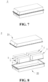
- the simplified diagram of the battery module 1 and the coating direction of each coating layer were as shown in Fig. 3 .
- a layered ternary transition metal oxide as a positive electrode active material accounting for 94% of the total weight of a slurry of a positive electrode layer 131, 2% of a conductive agent Super P, 2% of a binder PVDF, and 2% of a garnet-type solid-state electrolyte LLZO were mixed uniformly to obtain the slurry of the positive electrode layer 131.
- An appropriate amount of NMP (N-methyl pyrrolidone) was added into the slurry of the positive electrode layer 131.
- the slurry of the positive electrode layer 131 was evenly coated on a single side of aluminum foil of the positive electrode current collector 11, oven dried and cold pressed , and then cut to the same size as the AA'D'D surface in Fig. 4 , with the total negative electrode lead-out tab on one side being remained, so as to obtain the outermost layer positive electrode plate.
- Graphite as a negative electrode active material accounting for 96% of the total weight of a slurry of a negative electrode layer 133, 1% of the conductive agent Super P, 2% of a binder PTFE, and 1% of a PTFE binder were mixed uniformly to obtain the slurry of the negative electrode layer 133.
- the slurry of the negative electrode layer 133 was evenly coated on a single side of copper foil of the negative electrode current collector 12, oven dried and cold pressed , and then cut to the same size as the AA'D'D surface in Fig. 4 , with the total negative electrode lead-out tab on one side being remained, so as to obtain the outermost layer negative electrode plate.
- the conductive carbon black accounting for 90% of the total weight of the slurry of the current collector coating layer 14 and 10% of PVDF were evenly mixed to obtain the slurry of the current collector coating layer 14.
- An appropriate amount of NMP was added into the slurry of the current collector coating layer 14.
- the prepared outermost layer positive electrode plate was put into the case of the battery module, the outermost layer positive electrode plate was used as a base, a layer of the slurry of the solid-state electrolyte layer 132 was covered on the surface of the positive electrode coating layer of the outermost layer positive electrode plate, and they were hot pressed to obtain the solid-state electrolyte layer 132.
- the solid-state electrolyte layer 132 was used as a base, a layer of the slurry of the negative electrode layer 133 was evenly covered on the surface of the solid-state electrolyte layer 132, and they were cold pressed to obtain the negative electrode layer 133. So far, a solid-state battery cell 13 consisting of the positive electrode layer 131, the solid-state electrolyte layer 132, and the negative electrode layer 133 has been prepared.
- a layer of the slurry of the current collector coating layer 14 was evenly coated onto an upper surface of the negative electrode layer 133, oven dried and cold pressed to obtain the current collector coating layer 14.
- the coating was repeated according to the order of the positive electrode layer 131, the solid-state electrolyte layer 132, the negative electrode layer 133, and the current collector coating layer 14 sequentially. This step was repeated for 105 times (106 solid-state battery cells 13). After the 107th solid-state battery cell 13 was coated with the solid-state electrolyte layer 132, the prepared outermost layer negative electrode plate was covered on the solid-state electrolyte layer 132 and hot pressed to obtain the battery module 1 of the present application.
- the simplified diagram of the battery module 1 and the coating direction of each coating layer were as shown in Fig. 4 .
- a layered ternary transition metal oxide as a positive electrode active material accounting for 94% of the total weight of a slurry of a positive electrode layer 131, 2% of a conductive agent Super P, 2% of a binder PVDF, and 2% of a garnet-type solid-state electrolyte LLZO were mixed uniformly to obtain the slurry of the positive electrode layer 131.
- An appropriate amount of NMP was added into the slurry of the positive electrode layer 131.
- the slurry of the positive electrode layer 131 was evenly coated on a single side of aluminum foil of the positive electrode current collector 11, oven dried and cold pressed , and then cut to the same size as the AA'BB' surface in Fig. 5 , with the total negative electrode lead-out tab on one side being remained, so as to obtain the outermost layer positive electrode plate.
- Graphite as a negative electrode active material accounting for 96% of the total weight of a slurry of a negative electrode layer 133, 1% of the conductive agent Super P, 2% of a binder PTFE, and 1% of a PTFE binder were mixed uniformly to obtain the slurry of the negative electrode layer 133.
- the slurry of the negative electrode layer 133 was evenly coated on a single side of copper foil of the negative electrode current collector 12, oven dried and cold pressed , and then cut to the same size as the AA'BB' surface in Fig. 5 , with the total negative electrode lead-out tab on one side being remained, so as to obtain the outermost layer negative electrode plate.
- the conductive carbon black accounting for 90% of the total weight of the slurry of the current collector coating layer 14 and 10% of PVDF were evenly mixed to obtain the slurry of the current collector coating layer 14.
- An appropriate amount of NMP was added into the slurry of the current collector coating layer 14.
- the prepared outermost layer positive electrode plate was put into the case of the battery module, the outermost layer positive electrode plate was used as a base, a layer of the slurry of the solid-state electrolyte layer 132 was covered on the surface of the positive electrode coating layer of the outermost layer positive electrode plate, and they were hot pressed to obtain the solid-state electrolyte layer 132.
- the solid-state electrolyte layer 132 was used as a base, a layer of the slurry of the negative electrode layer 133 was evenly covered on the surface of the solid-state electrolyte layer 132, and they were cold pressed to obtain the negative electrode layer 133. So far, a solid-state battery cell 13 consisting of the positive electrode layer 131, the solid-state electrolyte layer 132, and the negative electrode layer 133 has been prepared.
- a layer of the slurry of the current collector coating layer 14 was evenly coated onto an upper surface of the negative electrode layer 133, oven dried and cold pressed to obtain the current collector coating layer 14.
- the coating was repeated according to the order of the positive electrode layer 131, the solid-state electrolyte layer 132, the negative electrode layer 133, and the current collector coating layer 14 sequentially. This step was repeated for 105 times (106 solid-state battery cells 13). After the 107th solid-state battery cell 13 was coated with the solid-state electrolyte layer 132, the prepared outermost layer negative electrode plate was covered on the solid-state electrolyte layer 132 and hot pressed to obtain the battery module 1 of the present application.
- the simplified diagram of the battery module 1 and the coating direction of each coating layer were as shown in Fig. 5 .
- a layered transition metal oxide as a positive electrode active material accounting for 94% of the total weight of a slurry of a positive electrode layer 131, 2% of a conductive agent Super P, 2% of a binder PVDF, and 2% of ⁇ -Al 2 O 3 were mixed uniformly to obtain the slurry of the positive electrode layer 131.
- An appropriate amount of NMP was added into the slurry of the positive electrode layer 131.
- the slurry of the positive electrode layer 131 was evenly coated on a single side of aluminum foil of the positive electrode current collector 11, oven dried and cold pressed , and then cut to the same size as the ABCD surface in Fig. 6 , with the total negative electrode lead-out tab on one side being remained, so as to obtain the outermost layer positive electrode plate.
- Graphite as a negative electrode active material accounting for 96% of the total weight of a slurry of a negative electrode layer 133, 1% of the conductive agent Super P, 2% of a binder PTFE, and 1% of a PTFE binder were mixed uniformly to obtain the slurry of the negative electrode layer 133.
- the slurry of the negative electrode layer 133 was evenly coated on a single side of copper foil of the negative electrode current collector 12, oven dried and cold pressed , and then cut to the same size as the A'B'C'D' surface in Fig. 6 , with the total negative electrode lead-out tab on one side being remained, so as to obtain the outermost layer negative electrode plate.
- the conductive carbon black accounting for 90% of the total weight of the slurry of the current collector coating layer 14 and 10% of PVDF were evenly mixed to obtain the slurry of the current collector coating layer 14.
- An appropriate amount of NMP was added into the slurry of the current collector coating layer 14.
- the prepared outermost layer positive electrode plate was put into the case of the battery module, the outermost layer positive electrode plate was used as a base, a layer of the slurry of the solid-state electrolyte layer 132 was covered on the surface of the positive electrode coating layer of the outermost layer positive electrode plate, and they were hot pressed to obtain the solid-state electrolyte layer 132.
- the solid-state electrolyte layer 132 was used as a base, a layer of the slurry of the negative electrode layer 133 was evenly covered on the surface of the solid-state electrolyte layer 132, and they were cold pressed to obtain the negative electrode layer 133. So far, a solid-state battery cell 13 consisting of the positive electrode layer 131, the solid-state electrolyte layer 132, and the negative electrode layer 133 has been prepared.
- a layer of the slurry of the current collector coating layer 14 was evenly coated onto an upper surface of the negative electrode layer 131, oven dried and cold pressed to obtain the current collector coating layer 14.
- the coating was repeated according to the order of the positive electrode layer 131, the solid-state electrolyte layer 132, the negative electrode layer 133, and the current collector coating layer 14 sequentially. This step was repeated for 105 times (106 solid-state battery cells 13). After the 107th solid-state battery cell 13 was coated with the solid-state electrolyte layer 132, the prepared outermost layer negative electrode plate was covered on the solid-state electrolyte layer 132 and hot pressed to obtain the battery module 1 of the present application.
- the simplified diagram of the battery module 1 and the coating direction of each coating layer were as shown in Fig. 6 .
Landscapes
- Chemical & Material Sciences (AREA)
- Chemical Kinetics & Catalysis (AREA)
- Electrochemistry (AREA)
- General Chemical & Material Sciences (AREA)
- Engineering & Computer Science (AREA)
- Materials Engineering (AREA)
- Manufacturing & Machinery (AREA)
- Composite Materials (AREA)
- Condensed Matter Physics & Semiconductors (AREA)
- General Physics & Mathematics (AREA)
- Inorganic Chemistry (AREA)
- Physics & Mathematics (AREA)
- Dispersion Chemistry (AREA)
- Secondary Cells (AREA)
- Battery Electrode And Active Subsutance (AREA)
- Primary Cells (AREA)
Abstract
Description
- The present application relates to the technical field of secondary batteries, and in particular to a battery module and a method for preparing the same, a battery pack and an electrical apparatus.
- In recent years, with the increasingly wide use of secondary ion batteries, secondary batteries are widely used in energy storage power systems such as water power, thermal power, wind power and solar power stations, as well as power tools, electric bicycles, electric motorcycles, electric vehicles, military equipment, aerospace and other fields.
- During the preparation of a battery pack, generally a battery cell is first prepared, then a plurality of battery cells are connected in series and parallel to form a battery module, and then the plurality of battery modules are assembled into the battery pack. The manufacturing of positive and negative electrode plates of a battery cell is generally formed by coating positive and negative electrode materials on current collectors of a metal foil material such as copper foil and aluminum foil. The use of current collectors such as the copper foil and the aluminum foil will increase the cost of a battery; and the preparation process of coating first and then assembling is cumbersome.
- Therefore, it has become one of the important research directions in the art how to reduce the production cost of the battery module and simplify the production process.
- The present application is made in view of the aforementioned problems, and one of its objectives is to provide a battery module that does not require to dispose current collectors of a metal foil material in positive and negative electrode plates, which can reduce the production cost and can simplify the preparation process.
- In order to achieve the aforementioned objective, a first aspect of the present application provides a battery module, including a positive electrode current collector, a negative electrode current collector, and a plurality of solid-state battery cells. The plurality of solid-state battery cells are stacked between the positive electrode current collector and the negative electrode current collector. Adjacent ones of the solid-state battery cells are electrically connected through a current collector coating layer. The solid-state battery cells at both ends are electrically connected to the positive electrode current collector and the negative electrode current collector respectively.
- In any embodiment of the present application, the current collector coating layer includes a conductive material.
- In any embodiment of the present application, the conductive material includes one or more of conductive carbon black, a carbon nanotube, graphene and a conductive polymer.
- In any embodiment of the present application, the weight percentage of the conductive material in the current collector coating layer is 10%-100%.
- In any embodiment of the present application, the current collector coating layer includes a first binder.
- In any embodiment of the present application, the first binder includes one or more of polyvinylidene fluoride, polytetrafluoroethylene, a vinylidene fluoride-tetrafluoroethylene-propylene terpolymer, a vinylidene fluoride-hexafluoropropylene-tetrafluoroethylene terpolymer, a tetrafluoroethylene-hexafluoropropylene copolymer and a fluorine-containing acrylate resin.
- In any embodiment of the present application, the weight percentage of the first binder in the current collector coating layer is ≤ 50%.
- In any embodiment of the present application, the current collector coating layer includes a first thickener.
- In any embodiment of the present application, the first thickener includes one or more of a carboxymethyl cellulose salt, a hydroxyethyl cellulose salt and a hydroxypropylmethyl cellulose salt.
- In any embodiment of the present application, the weight percentage of the first thickener in the current collector coating layer is ≤ 40%.
- In any embodiment of the present application, the current collector coating layer has a thickness of 1 µm-1,000 µm.
- In any embodiment of the present application, the current collector coating layer has a thickness of 4 µm-100 µm.
- In any embodiment of the present application, the current collector coating layer has a thickness of 6 µm-20 µm.
- In any embodiment of the present application, the solid-state battery cell includes a positive electrode layer, a solid-state electrolyte layer and a negative electrode layer. The solid-state electrolyte layer is located between the positive electrode layer and the negative electrode layer.
- In any embodiment of the present application, the positive electrode layer includes a positive electrode active material.
- In any embodiment of the present application, the positive electrode active material includes one or more of an oxide with a layered structure, a phosphate with an olivine structure, a compound with a spinel structure, an inorganic complex, sulfur and a sulfide.
- In any embodiment of the present application, the weight percentage of the positive electrode active material in the positive electrode coating is 50%-99.99%.
- In any embodiment of the present application, the positive electrode layer includes a first conductive agent.
- In any embodiment of the present application, the first conductive agent includes one or more of carbon materials with good conductivity, such as conductive carbon black, acetylene black, a conductive carbon fiber, a carbon nanotube and graphene powder.
- In any embodiment of the present application, the weight percentage of the first conductive agent in the positive electrode layer is ≤ 50%.
- In any embodiment of the present application, the positive electrode layer includes a first solid-state electrolyte.
- In any embodiment of the present application, the first solid-state electrolyte includes one or more of an inorganic sulfide solid electrolyte, an inorganic oxide solid electrolyte, and an organic polymer solid electrolyte.
- In any embodiment of the present application, the weight percentage of the first solid-state electrolyte in the positive electrode layer is ≤ 50%.
- In any embodiment of the present application, the positive electrode layer includes a second binder.
- In any embodiment of the present application, the second binder includes one or more of polyvinylidene fluoride, polytetrafluoroethylene, a vinylidene fluoride-tetrafluoroethylene-propylene terpolymer, a vinylidene fluoride-hexafluoropropylene-tetrafluoroethylene terpolymer, a tetrafluoroethylene-hexafluoropropylene copolymer and a fluorine-containing acrylate resin.
- In any embodiment of the present application, the weight percentage of the second binder in the positive electrode layer is ≤ 50%.
- In any embodiment of the present application, the positive electrode layer includes a second thickener.
- In any embodiment of the present application, the second thickener includes one or more of a carboxymethyl cellulose salt, a hydroxyethyl cellulose salt and a hydroxypropylmethyl cellulose salt.
- In any embodiment of the present application, the weight percentage of the second thickener in the positive electrode layer is ≤ 50%.
- In any embodiment of the present application, the negative electrode layer includes a negative electrode active material.
- In any embodiment of the present application, the negative electrode active material includes one or more of lithium titanate, hard carbon, graphite, activated carbon, lithium foil, a silicon-based material, a tin-based material, an antimony-based material, a lead-based material, phosphorus and a phosphorus compound.
- In any embodiment of the present application, the weight percentage of the negative electrode active material in the negative electrode layer is 50%-99.99%.
- In any embodiment of the present application, the negative electrode layer includes a second conductive agent.
- In any embodiment of the present application, the second conductive agent includes one or more of carbon materials with good conductivity, such as conductive carbon black, acetylene black, a conductive carbon fiber, a carbon nanotube and graphene powder.
- In any embodiment of the present application, the weight percentage of the second conductive agent in the negative electrode layer is ≤ 50%.
- In any embodiment of the present application, the negative electrode layer includes a second solid-state electrolyte.
- In any embodiment of the present application, the second solid-state electrolyte includes one or more of an inorganic sulfide solid electrolyte, an inorganic oxide solid electrolyte, and an organic polymer solid electrolyte.
- In any embodiment of the present application, the weight percentage of the second solid-state electrolyte in the negative electrode layer is ≤ 50%.
- In any embodiment of the present application, the negative electrode layer includes a third binder.
- In any embodiment of the present application, the third binder includes one or more of styrene butadiene rubber, polyacrylic acid, sodium polyacrylate, polyacrylamide, polyvinyl alcohol, sodium alginate, polymethacrylic acid, and carboxymethyl chitosan.
- In any embodiment of the present application, the weight percentage of the third binder in the negative electrode layer is ≤ 50%.
- In any embodiment of the present application, the solid-state electrolyte layer includes a solid-state electrolyte particle.
- In any embodiment of the present application, the solid-state electrolyte particle includes one or more of an inorganic sulfide solid electrolyte, an inorganic oxide solid electrolyte, and an organic polymer solid electrolyte.
- In any embodiment of the present application, the weight percentage of the solid-state electrolyte particle in the solid-state electrolyte layer is 50%-100%.
- In any embodiment of the present application, the solid-state electrolyte layer includes a fourth binder.
- In any embodiment of the present application, the fourth binder includes one or more of polyethylene oxide and a derivative thereof, polysiloxane and a derivative thereof, polyvinyl chloride and a derivative thereof, polycarbonate and a derivative thereof, polyacrylonitrile and a derivative thereof, polymethyl methacrylate and a derivative thereof, polyvinylidene fluoride and a derivative thereof, polytetrafluoroethylene and a derivative thereof, a vinylidene fluoride-tetrafluoroethylene-propylene terpolymer, a vinylidene fluoride-hexafluoropropylene-tetrafluoroethylene terpolymer, a tetrafluoroethylene-hexafluoropropylene copolymer, and a fluorine-containing acrylate resin.
- In any embodiment of the present application, the weight percentage of the fourth binder in the solid-state electrolyte layer is ≤ 50%.
- In any embodiment of the present application, the solid-state electrolyte layer includes a third thickener.
- In any embodiment of the present application, the third thickener includes one or more of a carboxymethyl cellulose salt, a hydroxyethyl cellulose salt and a hydroxypropylmethyl cellulose salt.
- In any embodiment of the present application, the weight percentage of the third thickener in the solid-state electrolyte layer is ≤ 40%.
- In any embodiment of the present application, the battery module further includes a positive electrode lead-out tab and a negative electrode lead-out tab. The positive electrode lead-out tab is electrically connected to the positive electrode current collector, and the negative electrode lead-out tab is electrically connected to the negative electrode current collector.
- A second aspect of the present application provides a method for preparing a battery module, which includes forming a stacked structure with a plurality of solid-state battery cells between a positive electrode current collector and a negative electrode current collector, connecting adjacent ones of the solid-state battery cells through a current collector coating layer; and electrically connecting the solid-state battery cells located at both ends to the positive electrode current collector and the negative electrode current collector respectively.
- A third aspect of the present application provides a battery pack including the battery module according to the first aspect of the present application, or including a battery module obtained by the method for preparing a battery module according to the second aspect of the present application.
- A fourth aspect of the present application provides an electrical apparatus including the battery pack according to the third aspect of the present application.
- In the present application, electrical connection is made between the adjacent battery cells through the current collector coating layer. That is, the current collector coating layer is disposed between the adjacent battery cells, so that there is no need to use a current collector of a metal foil material such as copper foil, aluminum foil and the like in the positive and negative electrode plates of the battery cells any more, which greatly reduces the use amount of the current collector of a metal foil material and reduces the production cost of the battery module; moreover, the battery module does not need to adopt a traditional manner of first coating the positive and negative electrode materials onto the current collectors to form battery cells, and then assembling to form a battery module, but instead adopts a manner of coating layer-by-layer to form coating layers, which simplifies the process flow of preparing the battery module.
-
-
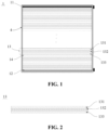
Fig. 1 is a schematic view of a battery module according to an embodiment of the present application. -
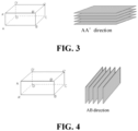
Fig. 2 is a schematic view of a battery cell in a battery module according to an embodiment of the present application. -
Fig. 3 is a simplified diagram (left panel) of a battery module and a schematic diagram (right panel) of a coating direction of a coating layer, according to Example 1 of the present application. -
Fig. 4 is a simplified diagram (left panel) of a battery module and a schematic diagram (right panel) of a coating direction of a coating layer, according to Example 2 of the present application. -
Fig. 5 is a simplified diagram (left panel) of a battery module and a schematic diagram (right panel) of a coating direction of a coating layer, according to Example 3 of the present application. -
Fig. 6 is a simplified diagram (left panel) of a battery module and a schematic diagram (right panel) of a coating direction of a coating layer, according to Example 4 of the present application. -
Fig. 7 is a schematic view of an embodiment of a battery pack. -
Fig. 8 is an exploded view ofFig. 7 . -
Fig. 9 is a schematic view of an electrical apparatus in which a battery pack is used a power source, according to an embodiment of the present application. - 1. battery module; 11. positive electrode current collector; 12. negative electrode current collector; 13. solid-state battery cell; 131. positive electrode layer; 132. solid-state electrolyte layer; 133. negative electrode layer; 14. current collector coating layer; 2. battery pack ; 21. upper box; 22. lower box; 3. electrical apparatus; 4. shell.
- Hereinafter, the embodiments of the battery module and a preparation method thereof, a battery pack and an electrical apparatus of the present application are specifically disclosed by referring to the detailed description of the drawings as appropriate. However, there are cases where unnecessary detailed descriptions are omitted. For example, there are cases where detailed descriptions of well-known items and repeated descriptions of actually identical structures are omitted. This is to avoid unnecessary verbosity in the following description and facilitate the understanding of those skilled in the art. In addition, the drawings and subsequent descriptions are provided for those skilled in the art to fully understand the present application, and are not intended to limit the subject matter recited in the claims.
- A "range" disclosed in the present application is defined in the form of a lower limit and an upper limit, with a given range being defined by the selection of a lower limit and an upper limit, and the selected lower and upper limits defining the boundaries of the particular range. A range defined in this manner may be inclusive or exclusive of end values, and may be arbitrarily combined, that is, any lower limit may be combined with any upper limit to form a range. For example, if ranges of 60-120 and 80-110 are listed for a particular parameter, it is understood that ranges of 60-110 and 80-120 are also contemplated. Additionally, if the
minimum range values maximum range values - Unless otherwise specified, all embodiments and optional embodiments of the present application may be combined with each other to form new technical solutions.
- Unless otherwise specified, all technical features and optional technical features of the present application may be combined with each other to form new technical solutions.
- Unless otherwise specified, all steps of the present application may be performed sequentially or randomly, and preferably sequentially. For example, the method includes steps (a) and (b), meaning that the method may include steps (a) and (b) performed sequentially, or may include steps (b) and (a) performed sequentially. For example, the reference to the method may further include step (c), meaning that step (c) may be added to the method in any order. For example, the method may include steps (a), (b) and (c), or may further include steps (a), (c) and (b), or may further include steps (c), (a) and (b), and the like.
- If not specifically stated, "including" and "comprising" mentioned in the present application indicate open inclusion or closed inclusion. For example, the "including" and "comprising" may indicate that it is also possible to include or comprise other components not listed, and it is also possible to include or comprise only the listed components.
- Unless otherwise specified, the term "or" is inclusive in the present application. By way of example, the phrase "A or B" means "A, B, or both A and B". More specifically, the condition "A or B" is satisfied by any of the following: A is true (or present) and B is false (or absent); A is false (or absent) and B is true (or present); or both A and B are true (or present).
- During the production of a traditional battery pack, a battery cell is first prepared, then a plurality of battery cells are connected the traditional series and parallel to form a battery module, and then the plurality of battery modules are assembled into the battery pack. The manufacturing of positive and negative electrode plates of a battery cell is generally formed by coating positive and negative electrode materials on current collectors of a metal foil material such as copper foil and aluminum foil. The use of current collectors such as the copper foil and the aluminum foil will increase the cost of a battery; and the preparation process of coating first and then assembling is cumbersome. Through research, the inventor has found a battery module in which a plurality of battery cells are stacked between a positive electrode current collector and a negative electrode current collector, and adjacent battery cells are connected by a current collector coating layer. The battery module can effectively reduce the production cost of the battery module and simplify the process flow of the preparation of the battery module.
- As shown in
Fig. 1 , in some embodiments, a first aspect of the present application provides abattery module 1. Thebattery module 1 includes a positive electrodecurrent collector 11, a negative electrodecurrent collector 12, and a plurality of solid-state battery cells 13. The plurality of solid-state battery cells 13 are stacked between the positive electrodecurrent collector 11 and the negative electrodecurrent collector 12. Adjacent ones of the solid-state battery cells 13 are electrically connected through a currentcollector coating layer 14. The solid-state battery cells 13 at both ends are electrically connected to the positive electrodecurrent collector 11 and the negative electrodecurrent collector 12 respectively. - In the present application, electrical connection is made between the
adjacent battery cells 13 through the currentcollector coating layer 14, so that there is no need to use a current collector of a metal foil material such as copper foil, aluminum foil and the like in the positive and negative electrode plates of the solid-state battery cells 13 any longer, which greatly reduces the use amount of the current collector of a metal foil material and reduces the production cost of thebattery module 1; moreover, thebattery module 1 does not need to adopt a traditional manner of first coating the positive and negative electrode materials onto the current collectors to form solid-state battery cells 13, and then assembling to form abattery module 1, which simplifies the process flow of preparing thebattery module 1. - In some embodiments, the current
collector coating layer 14 includes a conductive material. The conductive material includes one or more of conductive carbon black, a carbon nanotube, graphene and a conductive polymer. Thus, the conductive material in the currentcollector coating layer 14 includes one or more of conductive carbon black, a carbon nanotube, graphene and a conductive polymer, which can make the currentcollector coating layer 14 have good electronic conductivity and not have an ability of conducting lithium ions and sodium ions. That is, the formed currentcollector coating layer 14 can conduct electrons but not the lithium ions and sodium ions, and can function as a current collector of a metal foil material. - In some embodiments, the current
collector coating layer 14 can further include a first binder. The first binder as used may include one or more of polyvinylidene fluoride (PVDF), polytetrafluoroethylene (PTFE), a vinylidene fluoride-tetrafluoroethylene-propylene terpolymer, a vinylidene fluoride-hexafluoropropylene-tetrafluoroethylene terpolymer, a tetrafluoroethylene-hexafluoropropylene copolymer and a fluorine-containing acrylate resin. - In some embodiments, the current
collector coating layer 14 may further include a first thickener. The first thickener is sodium carboxymethyl cellulose (CMC-Na). - In some embodiments, in the current
collector coating layer 14, the weight percentage of the conductive material is 10%-100%, the weight percentage of the first binder is ≤ 50%, and the weight percentage of the first thickener is ≤ 40%. - It can be understood that the weight percentage of the conductive material in the current
collector coating layer 14 can be, but is not limited to 10%, 20%, 30%, 40%, 50%, 60%, 70%, 80%, 90%, and 100%; the weight percentage of the first binder in the currentcollector coating layer 14 can be, but is not limited to 0%, 10%, 20%, 30%, 40%, and 50%; and the weight percentage of the first thickener in the currentcollector coating layer 14 can be, but is not limited to 0%, 10%, 20%, 30%, and 40%. That is, the currentcollector coating layer 14 may be all conductive materials, may be a conductive material and partial of the first binder or the first thickener, or may also contain a conductive material, the first binder and the first thickener agent at the same time. - In some embodiments, the current
collector coating layer 14 has a thickness of 1 µm-1,000 µm. - It can be understood that the thickness of the current
collector coating layer 14 can be, but is not limited to 1 µm, 10 µm, 100 µm, 200 µm, 300 µm, 400 µm, 500 µm, 600 µm, 700 µm, 800 µm, 900 µm, and 1,000 µm. The specific thickness of the currentcollector coating layer 14 can be set according to actual needs. - As shown in
Fig. 2 , in some embodiments, the solid-state battery cell 13 includes apositive electrode layer 131, a solid-state electrolyte layer 132 and anegative electrode layer 133. The solid-state electrolyte layer 132 is located between thepositive electrode layer 131 and thenegative electrode layer 133. Therefore, in the present application, thepositive electrode layer 131, the solid-state electrolyte layer 132 and thenegative electrode layer 133 constituting the solid-state battery cell 13 can each be in the form of a coating layer. That is, thepositive electrode layer 131, the solid-state electrolyte layer 132 and thenegative electrode layer 133 are combined together by coating to form the solid-state battery cell 13. A current collector composed of metal foil does not need to be disposed in the solid-state battery cell 13. That is, it is not necessary to coat a positive electrode slurry onto the foil material of the positive electrode current collector to form a positive electrode plate, and it is not necessary to coat a negative electrode slurry onto the foil material of the negative electrode current collector to form the negative electrode plate. It is beneficial to reduce the production cost of thebattery module 1 and simplify the production process. - In some embodiments, the
positive electrode layer 131 includes a positive electrode active material. The positive electrode active material includes one or more of an oxide with a layered structure, a phosphate with an olivine structure, a compound with a spinel structure, an inorganic complex, sulfur and a sulfide. - In some embodiments, the
positive electrode layer 131 further includes a first conductive agent. The first conductive agent includes one or more of carbon materials with good conductivity, such as conductive carbon black, acetylene black, a conductive carbon fiber, a carbon nanotube and graphene powder. - In some embodiments, the
positive electrode layer 131 further includes a first solid-state electrolyte. The first solid-state electrolyte includes one or more of an inorganic sulfide solid electrolyte, an inorganic oxide solid electrolyte, and an organic polymer solid electrolyte. - In some embodiments, the
positive electrode layer 131 further includes a second binder. The second binder may include one or more of polyvinylidene fluoride (PVDF), polytetrafluoroethylene (PTFE), a vinylidene fluoride-tetrafluoroethylene-propylene terpolymer, a vinylidene fluoride-hexafluoropropylene-tetrafluoroethylene terpolymer, a tetrafluoroethylene-hexafluoropropylene copolymer and a fluorine-containing acrylate resin. - In some embodiments, the
positive electrode layer 131 further includes a second thickener. The second thickener is sodium carboxymethyl cellulose. - Further, in some embodiments, in the
positive electrode layer 131, the weight percentage of the positive electrode active material is 50%-99.99%, the weight percentage of the first conductive agent is ≤ 50%, the weight percentage of the first solid-state electrolyte is ≤ 50%, the weight percentage of the second binder is ≤ 50%, and the weight percentage of the second thickener is ≤ 50%. - It can be understood that, in the
positive electrode layer 131, the weight percentage of the positive electrode active material can be but is not limited to 50%, 60%, 70%, 80%, 90%, and 99.99%; the weight percentage of the first conductive agent can be but is not limited to 0%, 10%, 20%, 30%, 40%, and 50%; the weight percentage of the first solid-state electrolyte can be but is not limited to 0%, 10%, 20%, 30%, 40%, and 50%; the weight percentage of the second binder can be but is not limited to 0%, 10%, 20%, 30%, 40%, and 50%; and the weight percentage of the second thickener can be but is not limited to 0%, 10%, 20%, 30%, 40%, and 50%. - In some embodiments, the
negative electrode layer 133 includes a negative electrode active material. The negative electrode active material includes one or more of lithium titanate, hard carbon, graphite, activated carbon, lithium foil, a silicon-based material, a tin-based material, an antimony-based material, a lead-based material, phosphorus and a phosphorus compound. - In some embodiments, the
negative electrode layer 133 further includes a second conductive agent. The second conductive agent includes one or more of carbon materials with good conductivity, such as conductive carbon black, acetylene black, a conductive carbon fiber, a carbon nanotube and graphene powder. - In some embodiments, the
negative electrode layer 133 further includes a second solid-state electrolyte. The second solid-state electrolyte includes one or more of an inorganic sulfide solid electrolyte, an inorganic oxide solid electrolyte, and an organic polymer solid electrolyte. - In some embodiments, the
negative electrode layer 133 further includes a third binder. The third binder may be one or more of styrene butadiene rubber (SBR), polyacrylic acid (PAA), sodium polyacrylate (PAAS), polyacrylamide (PAM), polyvinyl alcohol (PVA), sodium alginate (SA), polymethacrylic acid (PMAA), and carboxymethyl chitosan (CMCS). - Further, in some embodiments, in the
negative electrode layer 133, the weight percentage of the negative electrode active material is 50%-99.99%, the weight percentage of the second conductive agent is ≤ 50%, the weight percentage of the second solid-state electrolyte is ≤ 50%, and the weight percentage of the third binder is ≤ 50%. - It can be understood that, in the
negative electrode layer 133, the weight percentage of the negative electrode active material can be but is not limited to 50%, 60%, 70%, 80%, 90%, and 99.99%; the weight percentage of the second conductive agent can be but is not limited to 0%, 10%, 20%, 30%, 40%, and 50%; the weight percentage of the second solid-state electrolyte can be but is not limited to 0%, 10%, 20%, 30%, 40%, and 50%; and the weight percentage of the third binder can be but is not limited to 0%, 10%, 20%, 30%, 40%, and 50%. - In some embodiments, the solid-
state electrolyte layer 132 includes a solid-state electrolyte particle. The solid-state electrolyte particle includes one or more of an inorganic sulfide solid electrolyte, an inorganic oxide solid electrolyte, and an organic polymer solid electrolyte. - In some embodiments, the solid-
state electrolyte layer 132 further includes a fourth binder. The fourth binder includes one or more of polyethylene oxide and a derivative thereof, polysiloxane and a derivative thereof, polycarbonate and a derivative thereof, polyacrylonitrile and a derivative thereof, polymethyl methacrylate and a derivative thereof, polyvinyl chloride and a derivative thereof, polyvinylidene fluoride and a derivative thereof, polytetrafluoroethylene and a derivative thereof, a vinylidene fluoride-tetrafluoroethylene-propylene terpolymer, a vinylidene fluoride-hexafluoropropylene-tetrafluoroethylene terpolymer, a tetrafluoroethylene-hexafluoropropylene copolymer, and a fluorine-containing acrylate resin. - In some embodiments, the solid-
state electrolyte layer 132 further includes a third thickener. The third thickener is sodium carboxymethyl cellulose. - Further, in some embodiments, in the solid-
state electrolyte layer 132, the weight percentage of the solid-state electrolyte particle is 50%-100%, the weight percentage of the fourth binder is ≤ 50%, and the weight percentage of the third thickener is ≤ 40%. - It can be understood that, in the solid-
state electrolyte layer 132, the weight percentage of the solid-state electrolyte particle can be, but is not limited to 50%, 60%, 70%, 80%, 90%, and 100%; the weight percentage of the fourth binder can be but is not limited to 0%, 10%, 20%, 30%, 40%, and 50%; and the weight percentage of the third thickener can be but is not limited to 0%, 10%, 20%, 30%, and 40%. - A second aspect of the present application further provides a method for preparing a
battery module 1, which includes forming a stacked structure with a plurality of solid-state battery cells 13 between a positive electrodecurrent collector 11 and a negative electrodecurrent collector 12, connecting adjacent ones of the solid-state battery cells 13 through a currentcollector coating layer 14; and electrically connecting the solid-state battery cells 13 located at both ends to the positive electrodecurrent collector 11 and the negative electrodecurrent collector 12 respectively. - The method for preparing a
battery module 1 described above in the present application forms a currentcollector coating layer 14 by coating a slurry of the current collector coating layer between the solid-state battery cell 13 and thesolid battery cell 13, so that there is no need to use the metal current collector formed from the metal foil material in the positive and negative electrodes of each solid-state battery cell 13, which greatly reduces the production cost of thebattery module 1; at the same time, it is not necessary to adopt the manner of firstly forming a solid-state battery cell 13 consisting of positive and negative electrode plates by coating the positive and negative electrode slurry onto the metal current collectors, and then assembling a plurality of the solid-state battery cells 13 to form thebattery module 1, which can effectively simplify the process flow of preparation. - A third aspect of the present application further provides a
battery pack 2. Thebattery pack 2 includes thebattery module 1 according to the first aspect of the present application, or includes abattery module 1 obtained by the method for preparing abattery module 1 according to the second aspect of the present application. - A fourth aspect of the present application further provides an
electrical apparatus 3 including thebattery pack 2 according to the third aspect of the present application. - The
battery module 1, thebattery pack 2 and theelectrical apparatus 3 of the present application will be further described hereafter with appropriate reference to the accompanying drawings. - Unless otherwise specified, the components, material types or contents of the battery as mentioned are applicable to both a lithium-ion secondary battery and a sodium-ion secondary battery.
- As shown in
Fig. 1 , in some embodiments, a plurality of solid-state battery cells 13 are assembled into abattery module 1, and the number of the solid-state battery cells 13 comprised in thebattery module 1 are multiple, and the specific number may be selected by those skilled in the art according to the application and capacity of thebattery module 1. - In the
battery module 1, a plurality of solid-state battery cells 13 may be sequentially arranged along a length direction of thebattery module 1. Of course, they can also be arranged in any other way. - Optionally, a
shell 4 having an accommodating space can be disposed outside thebattery module 1, and one ormore battery modules 1 of the present application are accommodated in the accommodating space to form a module-free integrated battery pack. An insulating layer may also be provided between each coating layer of thebattery module 1 and theshell 4 to prevent electronic conduction among different coating layers. - By controlling the number of solid-
state battery cells 13 in thebattery module 1, the output voltage of thebattery module 1 can be adjusted conveniently. For example, assuming that the voltage of one solid-state battery cell 13 is V0, the relationship between the number n of the solid-state battery cells 13 in thebattery module 1 and the output voltage V of thebattery module 1 is approximately: V = nV0. - By changing the surface area of the coating layer, the capacity of the
battery module 1 can be easily adjusted; and by adjusting the coating area (by default, the coating thickness of each positive electrode coating layer or negative electrode coating layer remains unchanged), the capacity value of thebattery module 1 can be changed conveniently. - As shown in
Figs. 7 and 8 , in some embodiments, theaforementioned battery module 1 may further be assembled into abattery pack 2, the number ofbattery modules 1 contained in thebattery pack 2 may be one or more, and the specific number can be selected by those skilled in the art according to the use and capacity of thebattery pack 2. - The
battery pack 2 may include a battery box and a plurality ofbattery modules 1 disposed in the battery box. The battery box includes anupper box body 21 and alower box body 22, theupper box body 21 can cover thelower box body 22 to form a closed space for accommodating the battery modules. The plurality ofbattery modules 1 may be arranged in the battery box in any manner. - It should be noted that, as shown in
Fig. 1 of the present application, thebattery module 1 having theshell 4 can be used alone as a module-free integrated battery pack; or alternatively one or more of theaforementioned battery modules 1 havingshells 4 are placed in a battery box to assemble into abattery pack 2 as shown inFigs. 7 and 8 for use. - As shown in
Fig. 9 , the present application further provides anelectrical apparatus 3. Theelectrical apparatus 3 includes at least one of thebattery module 1 or thebattery pack 2 provided in the present application. Thebattery module 1 or thebattery pack 2 can be used as a power source for theelectrical apparatus 3, or as an energy storage unit for theelectrical apparatus 3. Theelectrical apparatus 3 may include, but is not limited to, a mobile device (e.g. a mobile phone, and a laptop, etc.), an electric vehicle (e.g. an all-electric vehicle, a hybrid electric vehicle, a plug-in hybrid electric vehicle, an electric bicycle, an electric scooter, an electric golf cart, and an electric truck, etc.), an electric train, a ship, a satellite, an energy storage system, etc. - The
battery module 1 or thebattery pack 2 can be selected as theelectrical apparatus 3 according to the use requirements of the electrical apparatus. -
Fig. 9 shows anelectrical apparatus 3 as an example. Theelectrical apparatus 3 is an all-electric vehicle, a hybrid electric vehicle or a plug-in hybrid electric vehicle, and the like. In order to satisfy the requirements of theelectrical apparatus 3 for high power and high energy density of the battery, thebattery pack 2 orbattery module 1 can be employed. - In order to make the solved technical problems, technical solutions and beneficial effects of the present application more clear, the present application will be further described in detail in connection with examples and accompanying drawings. Apparently, the described examples are merely a part rather than all of the embodiments of the present application. The following description of at least one exemplary example is merely illustrative in nature and in no way serves as any limitation on the present application and applications thereof. Based on the embodiments in the present application, all other embodiments obtained by those of ordinary skills in the art without creative labor are within the claimed scope of the present application.
- If no specific technology or condition is indicated in the examples, it shall be carried out according to the technology or condition described in the literature in the art or according to product instructions. All of the used agents or instruments which are not specified with the manufacturer are conventional commercially-available products.
- A layered ternary transition metal oxide as a positive electrode active material accounting for 94% of the total weight of a slurry of a
positive electrode layer positive electrode layer 131. An appropriate amount of NMP (N-methyl pyrrolidone) was added into the slurry of thepositive electrode layer 131. - The slurry of the
positive electrode layer 131 was evenly coated on a single side of aluminum foil of the positive electrodecurrent collector 11, oven dried and cold pressed , and then cut to the same size as the ABCD surface inFig. 3 , with the total negative electrode lead-out tab on one side being remained, so as to obtain the outermost layer positive electrode plate. - Graphite as a negative electrode active material accounting for 96% of the total weight of a slurry of a
negative electrode layer negative electrode layer 133. - The slurry of the
negative electrode layer 133 was evenly coated on a single side of copper foil of the negative electrodecurrent collector 12, oven dried and cold pressed , and then cut to the same size as the A'B'C'D' surface inFig. 3 , with the total negative electrode lead-out tab on one side being remained, so as to obtain the outermost layer negative electrode plate. - The conductive carbon black accounting for 90% of the total weight of the slurry of the current
collector coating layer 14 and 10% of PVDF were evenly mixed to obtain the slurry of the currentcollector coating layer 14. An appropriate amount of NMP was added into the slurry of the currentcollector coating layer 14. - LLZO as the solid-state electrolyte material accounting for 98% of the total weight of the slurry of the solid-
state electrolyte layer state electrolyte layer 132. - The prepared outermost layer positive electrode plate was put into the case of the battery module, the outermost layer positive electrode plate was used as a base, a layer of the slurry of the solid-
state electrolyte layer 132 was covered on the surface of thepositive electrode layer 131 of the outermost layer positive electrode plate, and they were hot pressed to obtain the solid-state electrolyte layer 132. - The solid-
state electrolyte layer 132 was used as a base, a layer of the slurry of thenegative electrode layer 133 was evenly covered on the surface of the solid-state electrolyte layer 132, and they were cold pressed to obtain thenegative electrode layer 133. So far, a solid-state battery cell 13 consisting of thepositive electrode layer 131, the solid-state electrolyte layer 132, and thenegative electrode layer 133 has been prepared. - A layer of the slurry of the current
collector coating layer 14 was evenly coated onto an upper surface of thenegative electrode layer 133, oven dried and cold pressed to obtain the currentcollector coating layer 14. The coating was repeated according to the order of thepositive electrode layer 131, the solid-state electrolyte layer 132, thenegative electrode layer 133, and the currentcollector coating layer 14 sequentially. This step was repeated for 105 times (106 solid-state battery cells 13). After the 107th solid-state battery cell 13 was coated with the solid-state electrolyte layer 132, the prepared outermost layer negative electrode plate was covered on the solid-state electrolyte layer 132 and hot pressed to obtain thebattery module 1 of the present application. The simplified diagram of thebattery module 1 and the coating direction of each coating layer were as shown inFig. 3 . - A layered ternary transition metal oxide as a positive electrode active material accounting for 94% of the total weight of a slurry of a
positive electrode layer positive electrode layer 131. An appropriate amount of NMP (N-methyl pyrrolidone) was added into the slurry of thepositive electrode layer 131. - The slurry of the
positive electrode layer 131 was evenly coated on a single side of aluminum foil of the positive electrodecurrent collector 11, oven dried and cold pressed , and then cut to the same size as the AA'D'D surface inFig. 4 , with the total negative electrode lead-out tab on one side being remained, so as to obtain the outermost layer positive electrode plate. - Graphite as a negative electrode active material accounting for 96% of the total weight of a slurry of a
negative electrode layer negative electrode layer 133. - The slurry of the
negative electrode layer 133 was evenly coated on a single side of copper foil of the negative electrodecurrent collector 12, oven dried and cold pressed , and then cut to the same size as the AA'D'D surface inFig. 4 , with the total negative electrode lead-out tab on one side being remained, so as to obtain the outermost layer negative electrode plate. - The conductive carbon black accounting for 90% of the total weight of the slurry of the current
collector coating layer 14 and 10% of PVDF were evenly mixed to obtain the slurry of the currentcollector coating layer 14. An appropriate amount of NMP was added into the slurry of the currentcollector coating layer 14. - LLZO as the solid-state electrolyte material accounting for 98% of the total weight of the slurry of the solid-
state electrolyte layer state electrolyte layer 132. - The prepared outermost layer positive electrode plate was put into the case of the battery module, the outermost layer positive electrode plate was used as a base, a layer of the slurry of the solid-
state electrolyte layer 132 was covered on the surface of the positive electrode coating layer of the outermost layer positive electrode plate, and they were hot pressed to obtain the solid-state electrolyte layer 132. - The solid-
state electrolyte layer 132 was used as a base, a layer of the slurry of thenegative electrode layer 133 was evenly covered on the surface of the solid-state electrolyte layer 132, and they were cold pressed to obtain thenegative electrode layer 133. So far, a solid-state battery cell 13 consisting of thepositive electrode layer 131, the solid-state electrolyte layer 132, and thenegative electrode layer 133 has been prepared. - A layer of the slurry of the current
collector coating layer 14 was evenly coated onto an upper surface of thenegative electrode layer 133, oven dried and cold pressed to obtain the currentcollector coating layer 14. The coating was repeated according to the order of thepositive electrode layer 131, the solid-state electrolyte layer 132, thenegative electrode layer 133, and the currentcollector coating layer 14 sequentially. This step was repeated for 105 times (106 solid-state battery cells 13). After the 107th solid-state battery cell 13 was coated with the solid-state electrolyte layer 132, the prepared outermost layer negative electrode plate was covered on the solid-state electrolyte layer 132 and hot pressed to obtain thebattery module 1 of the present application. The simplified diagram of thebattery module 1 and the coating direction of each coating layer were as shown inFig. 4 . - A layered ternary transition metal oxide as a positive electrode active material accounting for 94% of the total weight of a slurry of a
positive electrode layer positive electrode layer 131. An appropriate amount of NMP was added into the slurry of thepositive electrode layer 131. - The slurry of the
positive electrode layer 131 was evenly coated on a single side of aluminum foil of the positive electrodecurrent collector 11, oven dried and cold pressed , and then cut to the same size as the AA'BB' surface inFig. 5 , with the total negative electrode lead-out tab on one side being remained, so as to obtain the outermost layer positive electrode plate. - Graphite as a negative electrode active material accounting for 96% of the total weight of a slurry of a
negative electrode layer negative electrode layer 133. - The slurry of the
negative electrode layer 133 was evenly coated on a single side of copper foil of the negative electrodecurrent collector 12, oven dried and cold pressed , and then cut to the same size as the AA'BB' surface inFig. 5 , with the total negative electrode lead-out tab on one side being remained, so as to obtain the outermost layer negative electrode plate. - The conductive carbon black accounting for 90% of the total weight of the slurry of the current
collector coating layer 14 and 10% of PVDF were evenly mixed to obtain the slurry of the currentcollector coating layer 14. An appropriate amount of NMP was added into the slurry of the currentcollector coating layer 14. - LLZO as the solid-state electrolyte material accounting for 98% of the total weight of the slurry of the solid-
state electrolyte layer state electrolyte layer 132. - The prepared outermost layer positive electrode plate was put into the case of the battery module, the outermost layer positive electrode plate was used as a base, a layer of the slurry of the solid-
state electrolyte layer 132 was covered on the surface of the positive electrode coating layer of the outermost layer positive electrode plate, and they were hot pressed to obtain the solid-state electrolyte layer 132. - The solid-
state electrolyte layer 132 was used as a base, a layer of the slurry of thenegative electrode layer 133 was evenly covered on the surface of the solid-state electrolyte layer 132, and they were cold pressed to obtain thenegative electrode layer 133. So far, a solid-state battery cell 13 consisting of thepositive electrode layer 131, the solid-state electrolyte layer 132, and thenegative electrode layer 133 has been prepared. - A layer of the slurry of the current
collector coating layer 14 was evenly coated onto an upper surface of thenegative electrode layer 133, oven dried and cold pressed to obtain the currentcollector coating layer 14. The coating was repeated according to the order of thepositive electrode layer 131, the solid-state electrolyte layer 132, thenegative electrode layer 133, and the currentcollector coating layer 14 sequentially. This step was repeated for 105 times (106 solid-state battery cells 13). After the 107th solid-state battery cell 13 was coated with the solid-state electrolyte layer 132, the prepared outermost layer negative electrode plate was covered on the solid-state electrolyte layer 132 and hot pressed to obtain thebattery module 1 of the present application. The simplified diagram of thebattery module 1 and the coating direction of each coating layer were as shown inFig. 5 . - A layered transition metal oxide as a positive electrode active material accounting for 94% of the total weight of a slurry of a
positive electrode layer positive electrode layer 131. An appropriate amount of NMP was added into the slurry of thepositive electrode layer 131. - The slurry of the
positive electrode layer 131 was evenly coated on a single side of aluminum foil of the positive electrodecurrent collector 11, oven dried and cold pressed , and then cut to the same size as the ABCD surface inFig. 6 , with the total negative electrode lead-out tab on one side being remained, so as to obtain the outermost layer positive electrode plate. - Graphite as a negative electrode active material accounting for 96% of the total weight of a slurry of a
negative electrode layer negative electrode layer 133. - The slurry of the
negative electrode layer 133 was evenly coated on a single side of copper foil of the negative electrodecurrent collector 12, oven dried and cold pressed , and then cut to the same size as the A'B'C'D' surface inFig. 6 , with the total negative electrode lead-out tab on one side being remained, so as to obtain the outermost layer negative electrode plate. - The conductive carbon black accounting for 90% of the total weight of the slurry of the current
collector coating layer 14 and 10% of PVDF were evenly mixed to obtain the slurry of the currentcollector coating layer 14. An appropriate amount of NMP was added into the slurry of the currentcollector coating layer 14. - β-Al2O3 as the solid-state electrolyte material accounting for 98% of the total weight of the slurry of the solid-
state electrolyte layer state electrolyte layer 132. - The prepared outermost layer positive electrode plate was put into the case of the battery module, the outermost layer positive electrode plate was used as a base, a layer of the slurry of the solid-
state electrolyte layer 132 was covered on the surface of the positive electrode coating layer of the outermost layer positive electrode plate, and they were hot pressed to obtain the solid-state electrolyte layer 132. - The solid-
state electrolyte layer 132 was used as a base, a layer of the slurry of thenegative electrode layer 133 was evenly covered on the surface of the solid-state electrolyte layer 132, and they were cold pressed to obtain thenegative electrode layer 133. So far, a solid-state battery cell 13 consisting of thepositive electrode layer 131, the solid-state electrolyte layer 132, and thenegative electrode layer 133 has been prepared. - A layer of the slurry of the current
collector coating layer 14 was evenly coated onto an upper surface of thenegative electrode layer 131, oven dried and cold pressed to obtain the currentcollector coating layer 14. The coating was repeated according to the order of thepositive electrode layer 131, the solid-state electrolyte layer 132, thenegative electrode layer 133, and the currentcollector coating layer 14 sequentially. This step was repeated for 105 times (106 solid-state battery cells 13). After the 107th solid-state battery cell 13 was coated with the solid-state electrolyte layer 132, the prepared outermost layer negative electrode plate was covered on the solid-state electrolyte layer 132 and hot pressed to obtain thebattery module 1 of the present application. The simplified diagram of thebattery module 1 and the coating direction of each coating layer were as shown inFig. 6 . - It should be noted that the present application is not limited to the aforementioned embodiments. The aforementioned embodiments are only examples, and the embodiments that have substantially the same composition as the technical idea and exert the same effects within the scope of the technical solution of the present application are all included in the technical scope of the present application. Furthermore, without departing from the scope of the subject matter of the present application, various modifications that can come into the mind of those skilled in the art applied to the embodiments and other embodiments constructed by combining partial composition elements of the embodiments are also included in the scope of the present application.
Claims (22)
- A battery module, comprising a positive electrode current collector, a negative electrode current collector, and a plurality of solid-state battery cells, wherein the plurality of solid-state battery cells are stacked between the positive electrode current collector and the negative electrode current collector, adjacent ones of the solid-state battery cells are electrically connected through a current collector coating layer, and the solid-state battery cells at both ends are electrically connected to the positive electrode current collector and the negative electrode current collector respectively.
- The battery module according to claim 1, wherein the current collector coating layer comprises a conductive material;optionally, the conductive material comprises one or more of conductive carbon black, a carbon nanotube, graphene and a conductive polymer; andoptionally, the weight percentage of the conductive material in the current collector coating layer is 10%-100%.
- The battery module according to claim 1 or 2, wherein the current collector coating layer comprises a first binder;optionally, the first binder comprises one or more of polyvinylidene fluoride, polytetrafluoroethylene, a vinylidene fluoride-tetrafluoroethylene-propylene terpolymer, a vinylidene fluoride-hexafluoropropylene-tetrafluoroethylene terpolymer, a tetrafluoroethylene-hexafluoropropylene copolymer and a fluorine-containing acrylate resin; andoptionally, the weight percentage of the first binder in the current collector coating layer is ≤ 50%.
- The battery module according to any one of claims 1 to 3, wherein the current collector coating layer comprises a first thickener;optionally, the first thickener comprises one or more of a carboxymethyl cellulose salt, a hydroxyethyl cellulose salt and a hydroxypropylmethyl cellulose salt; andoptionally, the weight percentage of the first thickener in the current collector coating layer is ≤ 40%.
- The battery module according to any one of claims 1 to 4, wherein the current collector coating layer has a thickness of 1 µm-1,000 µm;optionally, the current collector coating layer has a thickness of 4 µm-100 µm; andoptionally, the current collector coating layer has a thickness of 6 µm-20 µm.
- The battery module according to any one of claims 1 to 5, wherein the solid-state battery cell comprises a positive electrode layer, a solid-state electrolyte layer and a negative electrode layer, and the solid-state electrolyte layer is located between the positive electrode layer and the negative electrode layer.
- The battery module according to claim 6, wherein the positive electrode layer comprises a positive electrode active material;optionally, the positive electrode active material comprises one or more of an oxide with a layered structure, a phosphate with an olivine structure, a compound with a spinel structure, an inorganic complex, sulfur and a sulfide; andoptionally, the weight percentage of the positive electrode active material in the positive electrode layer is 50%-99.99%.
- The battery module according to claim 6 or 7, wherein the positive electrode layer comprises a first conductive agent;optionally, the first conductive agent comprises one or more of conductive carbon black, acetylene black, a conductive carbon fiber, a carbon nanotube and graphene powder; andoptionally, the weight percentage of the first conductive agent in the positive electrode layer is ≤ 50%.
- The battery module according to any one of claims 6 to 8, wherein the positive electrode layer comprises a first solid-state electrolyte;optionally, the first solid-state electrolyte comprises one or more of an inorganic sulfide solid electrolyte, an inorganic oxide solid electrolyte, and an organic polymer solid electrolyte; andoptionally, the weight percentage of the first solid-state electrolyte in the positive electrode layer is ≤ 50%.
- The battery module according to any one of claims 6 to 9, wherein the positive electrode layer comprises a second binder;optionally, the second binder comprises one or more of polyvinylidene fluoride, polytetrafluoroethylene, a vinylidene fluoride-tetrafluoroethylene-propylene terpolymer, a vinylidene fluoride-hexafluoropropylene-tetrafluoroethylene terpolymer, a tetrafluoroethylene-hexafluoropropylene copolymer and a fluorine-containing acrylate resin; andoptionally, the weight percentage of the second binder in the positive electrode layer is ≤ 50%.
- The battery module according to any one of claims 6 to 10, wherein the positive electrode layer comprises a second thickener;optionally, the second thickener comprises one or more of a carboxymethyl cellulose salt, a hydroxyethyl cellulose salt and a hydroxypropylmethyl cellulose salt; andoptionally, the weight percentage of the second thickener in the positive electrode layer is ≤ 50%.
- The battery module according to any one of claims 6 to 11, wherein the negative electrode layer comprises a negative electrode active material;optionally, the negative electrode active material comprises one or more of lithium titanate, hard carbon, graphite, activated carbon, lithium foil, a silicon-based material, a tin-based material, an antimony-based material, a lead-based material, phosphorus and a phosphorus compound; andoptionally, the weight percentage of the negative electrode active material in the negative electrode layer is 50%-99.99%.
- The battery module according to any one of claims 6 to 12, wherein the negative electrode layer comprises a second conductive agent;optionally, the second conductive agent comprises one or more of conductive carbon black, acetylene black, a conductive carbon fiber, a carbon nanotube and graphene powder; andoptionally, the weight percentage of the second conductive agent in the negative electrode layer is ≤ 50%.
- The battery module according to any one of claims 6 to 13, wherein the negative electrode layer comprises a second solid-state electrolyte;optionally, the second solid-state electrolyte comprises one or more of an inorganic sulfide solid electrolyte, an inorganic oxide solid electrolyte, and an organic polymer solid electrolyte; andoptionally, the weight percentage of the second solid-state electrolyte in the negative electrode layer is ≤ 50%.
- The battery module according to any one of claims 6 to 14, wherein the negative electrode layer comprises a third binder;optionally, the third binder comprises one or more of styrene butadiene rubber, polyacrylic acid, sodium polyacrylate, polyacrylamide, polyvinyl alcohol, sodium alginate, polymethacrylic acid, and carboxymethyl chitosan; andoptionally, the weight percentage of the third binder in the negative electrode layer is ≤ 50%.
- The battery module according to any one of claims 6 to 15, wherein the solid-state electrolyte layer comprises a solid-state electrolyte particle;optionally, the solid-state electrolyte particle comprises one or more of an inorganic sulfide solid electrolyte, an inorganic oxide solid electrolyte, and an organic polymer solid electrolyte; andoptionally, the weight percentage of the solid-state electrolyte particle in the solid-state electrolyte layer is 50%-100%.
- The battery module according to any one of claims 6 to 16, wherein the solid-state electrolyte layer comprises a fourth binder;optionally, the fourth binder comprises one or more of polyethylene oxide and a derivative thereof, polysiloxane and a derivative thereof, polyvinyl chloride and a derivative thereof, polycarbonate and a derivative thereof, polyacrylonitrile and a derivative thereof, polymethyl methacrylate and a derivative thereof, polyvinylidene fluoride and a derivative thereof, polytetrafluoroethylene and a derivative thereof, a vinylidene fluoride-tetrafluoroethylene-propylene terpolymer, a vinylidene fluoride-hexafluoropropylene-tetrafluoroethylene terpolymer, a tetrafluoroethylene-hexafluoropropylene copolymer, and a fluorine-containing acrylate resin; andoptionally, the weight percentage of the fourth binder in the solid-state electrolyte layer is ≤ 50%.
- The battery module according to any one of claims 6 to 17, wherein the solid-state electrolyte layer comprises a third thickener;optionally, the third thickener comprises one or more of a carboxymethyl cellulose salt, a hydroxyethyl cellulose salt and a hydroxypropylmethyl cellulose salt; andoptionally, the weight percentage of the third thickener in the solid-state electrolyte layer is ≤ 40%.
- The battery module according to any one of claims 1 to 18, wherein the battery module further comprises a positive electrode lead-out tab and a negative electrode lead-out tab, the positive electrode lead-out tab is electrically connected to the positive electrode current collector, and the negative electrode lead-out tab is electrically connected to the negative electrode current collector.
- A method for preparing the battery module according to any one of claims 1 to 19, comprising forming a stacked structure with a plurality of solid-state battery cells between a positive electrode current collector and a negative electrode current collector, connecting adjacent ones of the solid-state battery cells through a current collector coating layer; and electrically connecting the solid-state battery cells located at both ends to the positive electrode current collector and the negative electrode current collector respectively.
- A battery pack comprising the battery module according to any one of claims 1 to 19 or a battery module obtained by the method for preparing a battery module according to claim 20.
- An electrical apparatus comprising the battery pack according to claim 21.
Applications Claiming Priority (1)
| Application Number | Priority Date | Filing Date | Title |
|---|---|---|---|
| PCT/CN2022/125289 WO2024077584A1 (en) | 2022-10-14 | 2022-10-14 | Battery module and preparation method therefor, and battery pack and electric apparatus |
Publications (2)
| Publication Number | Publication Date |
|---|---|
| EP4507059A1 true EP4507059A1 (en) | 2025-02-12 |
| EP4507059A4 EP4507059A4 (en) | 2025-08-06 |
Family
ID=90668479
Family Applications (1)
| Application Number | Title | Priority Date | Filing Date |
|---|---|---|---|
| EP22961772.5A Pending EP4507059A4 (en) | 2022-10-14 | 2022-10-14 | Battery module and manufacturing method therefor, as well as battery pack and electrical device |
Country Status (4)
| Country | Link |
|---|---|
| US (1) | US20250062500A1 (en) |
| EP (1) | EP4507059A4 (en) |
| CN (1) | CN118541845A (en) |
| WO (1) | WO2024077584A1 (en) |
Families Citing this family (1)
| Publication number | Priority date | Publication date | Assignee | Title |
|---|---|---|---|---|
| CN118763289A (en) * | 2024-06-27 | 2024-10-11 | 福建特钠新能源科技有限公司 | A method for preparing a solid-state battery |
Family Cites Families (8)
| Publication number | Priority date | Publication date | Assignee | Title |
|---|---|---|---|---|
| JPH11214034A (en) * | 1998-01-23 | 1999-08-06 | Sony Corp | Solid electrolyte battery and method of manufacturing the same |
| CN103053061B (en) * | 2010-08-09 | 2015-05-06 | 株式会社村田制作所 | Laminated solid battery |
| CN110098430A (en) * | 2018-01-30 | 2019-08-06 | 财团法人工业技术研究院 | Solid electrolyte and solid state battery |
| WO2020059550A1 (en) * | 2018-09-18 | 2020-03-26 | 富士フイルム株式会社 | Production method for all-solid secondary battery layered member, and production method for all-solid secondary battery |
| WO2020116090A1 (en) * | 2018-12-06 | 2020-06-11 | 株式会社村田製作所 | Solid state battery |
| DE202020005749U1 (en) * | 2020-06-26 | 2022-04-13 | InvestHG UG (haftungsbeschränkt) | energy storage |
| JP7701167B2 (en) * | 2021-03-11 | 2025-07-01 | 本田技研工業株式会社 | solid state battery |
| CN113675480A (en) * | 2021-07-19 | 2021-11-19 | 华南理工大学 | Lithium ion battery cell with sandwich structure, electric pile and preparation method thereof |
-
2022
- 2022-10-14 WO PCT/CN2022/125289 patent/WO2024077584A1/en not_active Ceased
- 2022-10-14 CN CN202280089057.6A patent/CN118541845A/en active Pending
- 2022-10-14 EP EP22961772.5A patent/EP4507059A4/en active Pending
-
2024
- 2024-11-05 US US18/937,557 patent/US20250062500A1/en active Pending
Also Published As
| Publication number | Publication date |
|---|---|
| CN118541845A (en) | 2024-08-23 |
| WO2024077584A1 (en) | 2024-04-18 |
| EP4507059A4 (en) | 2025-08-06 |
| US20250062500A1 (en) | 2025-02-20 |
Similar Documents
| Publication | Publication Date | Title |
|---|---|---|
| KR102854877B1 (en) | Negative electrode sheet and method for manufacturing the same, secondary battery, battery module, battery pack and electric device | |
| EP4246647A1 (en) | Electrolyte, secondary battery, and electric device | |
| CN115832299A (en) | Slurry, positive pole piece, secondary battery, battery module, battery pack and electric device | |
| US12586792B2 (en) | Negative electrode plate and preparation method therefor, secondary battery, battery module, battery pack and power consuming device | |
| EP4325593A1 (en) | Electrode plate, electrode assembly and secondary battery | |
| CN115832220B (en) | Positive electrode sheet and lithium ion battery comprising the same | |
| JP2023547000A (en) | Silicon carbon negative electrode materials, negative electrode plates, secondary batteries, battery modules, battery packs and power consumption devices | |
| EP4187684B1 (en) | Battery pack | |
| US20250379220A1 (en) | Positive electrode plate and manufacturing method therefor, battery cell, battery and electrical apparatus | |
| WO2022199301A1 (en) | Anode plate of lithium ion battery and application thereof | |
| EP4195349B1 (en) | Secondary battery | |
| CN115832181B (en) | Positive electrode plate, preparation method thereof, secondary battery, battery module, battery pack and power utilization device | |
| CN117810460B (en) | Battery pack and electric equipment | |
| KR102778910B1 (en) | Negative electrode plates, secondary batteries, battery modules, battery packs and electrical devices | |
| US20250062500A1 (en) | Battery module and preparation method thereof, battery pack and electrical apparatus | |
| WO2024212200A1 (en) | Negative electrode sheet, secondary battery comprising same, and electric device | |
| EP4239781A1 (en) | Separator and secondary battery related thereto, battery module, battery pack, and electronic device | |
| CN118676368A (en) | Negative electrode sheet additive, negative electrode slurry, negative electrode sheet and related devices | |
| WO2023082039A1 (en) | Negative electrode sheet, secondary battery, battery module, battery pack, and electric device | |
| CN118943280B (en) | Negative electrode plate, secondary battery and electrical device | |
| CN121039816A (en) | Battery cells, batteries and electrical devices | |
| CN116666561A (en) | Negative electrode sheet and secondary battery and electrical device containing it | |
| JP2023550216A (en) | Electrode assemblies, secondary batteries, battery modules, battery packs and power consumption devices | |
| WO2023133805A1 (en) | Positive electrode composite material for lithium ion secondary battery, positive electrode and battery | |
| JP7717971B2 (en) | Electrode assembly and secondary battery, battery module, battery pack, and power consumption device including the same |
Legal Events
| Date | Code | Title | Description |
|---|---|---|---|
| STAA | Information on the status of an ep patent application or granted ep patent |
Free format text: STATUS: THE INTERNATIONAL PUBLICATION HAS BEEN MADE |
|
| PUAI | Public reference made under article 153(3) epc to a published international application that has entered the european phase |
Free format text: ORIGINAL CODE: 0009012 |
|
| STAA | Information on the status of an ep patent application or granted ep patent |
Free format text: STATUS: REQUEST FOR EXAMINATION WAS MADE |
|
| 17P | Request for examination filed |
Effective date: 20241106 |
|
| AK | Designated contracting states |
Kind code of ref document: A1 Designated state(s): AL AT BE BG CH CY CZ DE DK EE ES FI FR GB GR HR HU IE IS IT LI LT LU LV MC ME MK MT NL NO PL PT RO RS SE SI SK SM TR |
|
| A4 | Supplementary search report drawn up and despatched |
Effective date: 20250703 |
|
| RIC1 | Information provided on ipc code assigned before grant |
Ipc: H01M 10/0585 20100101AFI20250627BHEP Ipc: H01M 10/0562 20100101ALI20250627BHEP Ipc: H01M 10/0565 20100101ALI20250627BHEP |
|
| DAV | Request for validation of the european patent (deleted) | ||
| DAX | Request for extension of the european patent (deleted) |