EP4507046A1 - Pre-stacking device, battery processing apparatus and pre-stacking method - Google Patents
Pre-stacking device, battery processing apparatus and pre-stacking method Download PDFInfo
- Publication number
- EP4507046A1 EP4507046A1 EP23833564.0A EP23833564A EP4507046A1 EP 4507046 A1 EP4507046 A1 EP 4507046A1 EP 23833564 A EP23833564 A EP 23833564A EP 4507046 A1 EP4507046 A1 EP 4507046A1
- Authority
- EP
- European Patent Office
- Prior art keywords
- battery cells
- station
- tray
- along
- assembly
- Prior art date
- Legal status (The legal status is an assumption and is not a legal conclusion. Google has not performed a legal analysis and makes no representation as to the accuracy of the status listed.)
- Pending
Links
- 238000000034 method Methods 0.000 title claims abstract description 52
- 238000012545 processing Methods 0.000 title claims abstract description 7
- 238000003825 pressing Methods 0.000 claims description 48
- 238000011068 loading method Methods 0.000 claims description 21
- 238000001514 detection method Methods 0.000 claims description 15
- 238000005096 rolling process Methods 0.000 claims description 12
- 230000008569 process Effects 0.000 description 29
- 230000033001 locomotion Effects 0.000 description 14
- 238000004519 manufacturing process Methods 0.000 description 14
- 238000013459 approach Methods 0.000 description 5
- 230000008901 benefit Effects 0.000 description 3
- 230000009471 action Effects 0.000 description 2
- 238000009434 installation Methods 0.000 description 2
- 239000000853 adhesive Substances 0.000 description 1
- 230000001070 adhesive effect Effects 0.000 description 1
- 239000002390 adhesive tape Substances 0.000 description 1
- 238000011161 development Methods 0.000 description 1
- 230000000694 effects Effects 0.000 description 1
- 238000004146 energy storage Methods 0.000 description 1
- 230000003993 interaction Effects 0.000 description 1
- 238000012986 modification Methods 0.000 description 1
- 230000004048 modification Effects 0.000 description 1
- 238000006467 substitution reaction Methods 0.000 description 1
Images



Classifications
-
- H—ELECTRICITY
- H01—ELECTRIC ELEMENTS
- H01M—PROCESSES OR MEANS, e.g. BATTERIES, FOR THE DIRECT CONVERSION OF CHEMICAL ENERGY INTO ELECTRICAL ENERGY
- H01M10/00—Secondary cells; Manufacture thereof
- H01M10/04—Construction or manufacture in general
- H01M10/0404—Machines for assembling batteries
-
- H—ELECTRICITY
- H01—ELECTRIC ELEMENTS
- H01M—PROCESSES OR MEANS, e.g. BATTERIES, FOR THE DIRECT CONVERSION OF CHEMICAL ENERGY INTO ELECTRICAL ENERGY
- H01M10/00—Secondary cells; Manufacture thereof
- H01M10/04—Construction or manufacture in general
- H01M10/0481—Compression means other than compression means for stacks of electrodes and separators
-
- H—ELECTRICITY
- H01—ELECTRIC ELEMENTS
- H01M—PROCESSES OR MEANS, e.g. BATTERIES, FOR THE DIRECT CONVERSION OF CHEMICAL ENERGY INTO ELECTRICAL ENERGY
- H01M50/00—Constructional details or processes of manufacture of the non-active parts of electrochemical cells other than fuel cells, e.g. hybrid cells
- H01M50/20—Mountings; Secondary casings or frames; Racks, modules or packs; Suspension devices; Shock absorbers; Transport or carrying devices; Holders
- H01M50/204—Racks, modules or packs for multiple batteries or multiple cells
- H01M50/207—Racks, modules or packs for multiple batteries or multiple cells characterised by their shape
- H01M50/209—Racks, modules or packs for multiple batteries or multiple cells characterised by their shape adapted for prismatic or rectangular cells
-
- H—ELECTRICITY
- H01—ELECTRIC ELEMENTS
- H01M—PROCESSES OR MEANS, e.g. BATTERIES, FOR THE DIRECT CONVERSION OF CHEMICAL ENERGY INTO ELECTRICAL ENERGY
- H01M2220/00—Batteries for particular applications
- H01M2220/20—Batteries in motive systems, e.g. vehicle, ship, plane
-
- Y—GENERAL TAGGING OF NEW TECHNOLOGICAL DEVELOPMENTS; GENERAL TAGGING OF CROSS-SECTIONAL TECHNOLOGIES SPANNING OVER SEVERAL SECTIONS OF THE IPC; TECHNICAL SUBJECTS COVERED BY FORMER USPC CROSS-REFERENCE ART COLLECTIONS [XRACs] AND DIGESTS
- Y02—TECHNOLOGIES OR APPLICATIONS FOR MITIGATION OR ADAPTATION AGAINST CLIMATE CHANGE
- Y02E—REDUCTION OF GREENHOUSE GAS [GHG] EMISSIONS, RELATED TO ENERGY GENERATION, TRANSMISSION OR DISTRIBUTION
- Y02E60/00—Enabling technologies; Technologies with a potential or indirect contribution to GHG emissions mitigation
- Y02E60/10—Energy storage using batteries
-
- Y—GENERAL TAGGING OF NEW TECHNOLOGICAL DEVELOPMENTS; GENERAL TAGGING OF CROSS-SECTIONAL TECHNOLOGIES SPANNING OVER SEVERAL SECTIONS OF THE IPC; TECHNICAL SUBJECTS COVERED BY FORMER USPC CROSS-REFERENCE ART COLLECTIONS [XRACs] AND DIGESTS
- Y02—TECHNOLOGIES OR APPLICATIONS FOR MITIGATION OR ADAPTATION AGAINST CLIMATE CHANGE
- Y02P—CLIMATE CHANGE MITIGATION TECHNOLOGIES IN THE PRODUCTION OR PROCESSING OF GOODS
- Y02P70/00—Climate change mitigation technologies in the production process for final industrial or consumer products
- Y02P70/50—Manufacturing or production processes characterised by the final manufactured product
Definitions
- the present application relates to the technical field of batteries and in particular to a pre-stacking device, battery processing equipment and pre-stacking method.
- the present application provides a pre-stacking device, battery processing equipment and a pre-stacking method.
- the present application provides a pre-stacking device including a mounting seat, a tray, and a pushing assembly.
- the mounting seat includes at least one station, the tray is arranged on the mounting seat, the tray is used to carry at least two battery cells arranged along their thickness direction, and the pushing assembly is movably arranged at one of the stations along the thickness direction of the battery cells.
- the pushing assembly is used to drive the battery cells on the tray to move along the thickness direction of the battery cells on the corresponding station, so that every two adjacent battery cells are attached to each other.
- the close stacking of the multiple battery cells along their thickness direction can be realized through the pushing operation by the pushing assembly when the tray and the battery cells on the tray move to the station where the pushing assembly is located, thereby providing an automatic stacking device.
- the stations include a first station, a second station and a third station arranged at intervals in the circumferential direction, and the tray is configured to rotate between the first station, the second station and the third station.
- the first station is used for loading the battery cells on the tray
- the pushing assembly is arranged on the second station
- the third station is used for unloading the battery cells that have been attached to each other off the tray.
- a simple multi-station stacking procedure is formed to realize the loading, stacking, and unloading process of the battery cells.
- the placement and removal of battery cells on different stations do not affect each other, and pre-stacking is divided into multiple steps that proceed in a cycle to realize automatic pre-stacking, so that the efficiency of battery cell pre-stacking is improved, the pre-stacking stability is good, and production is conducted on different stations synchronously without affecting each other, thereby improving production efficiency.
- the mounting seat includes a base and a support member rotatably arranged on the base, the base has a first station, a second station and a third station arranged at intervals along its circumferential direction, and multiple trays are provided on the support member and rotate along with the support member. When one of the trays moves to the first station, there is a tray on each of the second station and the third station.
- the tray on the fourth station when the tray on the fourth station is loading, the tray on the fourth station is pre-stacking, and the tray on the second station is unloading, which goes round and round without affecting each other, thereby improving production efficiency.
- the mounting seat also has a fourth station arranged at an interval between the first station and the second station.
- a fourth station arranged at an interval between the first station and the second station.
- pre-stacking of formula cells can be realized simultaneously, thereby improving production efficiency.
- the pre-stacking device further includes a positioning assembly arranged at the first station to fix the tray on the first station.
- the pre-stacking device further includes a first clamping assembly configured to be movably arranged on the mounting seat along the height direction of the battery cells.
- the first clamping assembly can clamp the battery cells on the tray along the width direction of the battery cells when the tray moves to the second station.
- the first clamping assembly can smoothly realize clamping of the battery cells when the battery cells move to the second station, thereby ensuring the effectiveness of pushing by the pushing assembly. Moreover, the first clamping assembly does not affect the movement of the battery cell along with the tray in other cases, and the movement of the battery cell among multiple stations can be smoothly realized.
- the pre-stacking device further includes a second clamping assembly arranged on the tray to clamp the battery cells on the tray along the width direction of the battery cells.
- the first clamping assembly is arranged at an interval from the second clamping assembly along the height direction of the battery cells.
- the second clamping assembly and the first clamping assembly can be spaced apart from each other along the height direction of the battery cell and can clamp and fix the opposite ends of the battery cell in the height direction, so that the friction between the battery cell and the supporting surface thereof can be kept in balance, thereby making the pre-stacking process of the battery cells smoother, reducing the probability of the battery cells falling during the pre-stacking process, and making stacking of the battery cells more stable.
- both the first clamping assembly and the second clamping assembly include a first clamping member and a second clamping member respectively arranged on two sides of the tray along the width direction of the battery cell, and at least one of the first clamping member and the second clamping member is configured to be movably arranged along the width direction of the battery cell.
- the battery cell can be smoothly clamped, so that the battery cell can be stably placed on the tray, and the battery cell can be kept in balance during pressing.
- the second clamping assembly further includes a main body and a first driving member, and the first driving member is connected between the main body and the mounting seat to drive the main body to move along the height direction of the battery cell; where the first clamping member and the second clamping member in the second clamping assembly are arranged on the main body.
- the first clamping member and the second clamping member can be brought along to move along the height direction of the battery cell, so as to clamp and fix the battery cell during pressing and avoid the battery cell when it does not need to be pressed.
- the second clamping assembly further includes a limiting assembly arranged on the main body and located between the first clamping member and the second clamping member, and the limiting assembly is used to press the battery cells on the tray along the height direction of the battery cells.
- the limiting assembly is located between the first clamping member and the second clamping member and can press the battery cell downwards, so that the battery cell can be stably supported on the support surface of the tray.
- the battery cell can be more stable during the pre-stacking process.
- the limiting assembly includes an adjustment member and a pressing member, the adjustment member is telescopically connected between the main body and the pressing member along the height direction of the battery cell, and the pressing member is used to press the battery cells on the tray along the height direction of the battery cells.
- the battery cell can be pressed against the tray more stably, so that the battery cell can be kept in balance in the process of being pushed.
- the pressing member includes a connecting portion and a rolling portion
- the connecting portion is connected to the adjustment member
- the rolling portion is rollably arranged on the connecting portion along the thickness direction of the battery cell to be rollably pressed against the battery cells on the tray along the height direction of the battery cells.
- the pushing assembly includes an abutting member and a pushing member, the abutting member is arranged on the tray, the pushing member is movably arranged on the mounting seat along the thickness direction of the battery cell, and the abutting member and the pushing member are respectively arranged on two sides of the tray along the thickness direction of the battery cell, and the pushing member is configured to be able to push the battery cells on the tray along the thickness direction of the battery cells to abut against the abutting member.
- the mounting seat includes a base and a support member rotatably arranged on the base, and the support member has a pressing position and at least two pre-stacking positions arranged at intervals along the circumferential direction thereof, and a tray and the first clamping assembly are correspondingly arranged at each pre-stacking position; the second clamping assembly and the pushing assembly are both arranged at the pressing position;
- the second clamping assembly is configured to, when one of the trays is rotated to the pressing position, clamp the battery cells on the tray along the width direction of the battery cells; and the pushing assembly is configured to, when one of the trays is rotated to the pressing position, push the battery cells on the tray.
- the battery cells can be stacked synchronously at multiple pre-stacking positions, and sequentially rotated to the pressing positions for pressing, thereby improving the efficiency of the process of battery cell pre-stacking.
- the pre-stacking device further includes a detection assembly arranged on the tray.
- the detection assembly is used to detect whether there is a battery cell on the tray.
- the pushing assembly can be intelligently controlled according to the detection structure of the detection assembly, so as to avoid safety accidents.
- the present application provides a battery processing equipment, including the above-mentioned pre-stacking device.
- the present application provides a pre-stacking method, including the steps of:
- a simple multi-station stacking procedure is formed to realize the loading, stacking, and unloading process of the battery cells.
- the placement and removal of battery cells on different stations do not affect each other, and pre-stacking is divided into multiple steps that proceed in a cycle to realize automatic pre-stacking, so that the efficiency of battery cell pre-stacking is improved, the pre-stacking stability is good, and production is conducted on different stations synchronously without affecting each other, thereby improving production efficiency.
- this method further includes the step of: controlling a tray to move to a fourth station of the mounting seat, and placing at least two battery cells on the tray along their thickness direction.
- the pre-stacking device of the present application can not only realize simultaneous stacking and unloading of the formula cells, but also realize multiple loadings of the battery cells in the same placement direction, thereby avoiding falling of the battery cells due to excessive loading at one time.
- this method further includes, after placing at least two battery cells on the tray along their thickness direction: clamping the battery cells on the tray along the width direction of the battery cells, the width direction of the battery cells being perpendicular to the thickness direction of the battery cells.
- clamping of the battery cell can be smoothly realized when the battery cell moves to the second station, thereby ensuring the effectiveness of pushing by the pushing assembly. Moreover, in other cases, the movement of the battery cell following the tray is not affected, and the movement of the battery cell among a plurality of stations can be smoothly realized.
- an embodiment means that a particular feature, structure, or characteristic described in connection with the embodiment can be included in at least one embodiment of the present application.
- the appearance of this phrase in various places in the specification does not necessarily refer to the same embodiment, nor is it a separate or alternative embodiment that is mutually exclusive with other embodiments. It is explicitly and implicitly understood by those skilled in the art that the embodiments described herein may be combined with other embodiments.
- a plurality of refers to two or more (including two), and similarly, “multiple groups” refers to two or more (including two) groups, and “multiple sheets” refers to two or more (including two) sheets.
- the technical terms “mount,” “join,” “connect,” “fix,” etc. should be understood in a broad sense, such as, a fixed connection, a detachable connection, or an integral connection; a mechanical connection, or an electrical connection; a direct connection, an indirect connection through an intermediate medium, an internal connection of two elements, or interaction between two elements.
- the specific meanings of the above terms in the embodiments of the present application can be understood according to specific situations.
- power batteries are more and more widely used.
- the power batteries are used in energy storage power source systems such as hydraulic, thermal, wind and solar power stations as well as in electric vehicles such as electric bicycles, electric motorcycles and electric cars, and other fields.
- energy storage power source systems such as hydraulic, thermal, wind and solar power stations
- electric vehicles such as electric bicycles, electric motorcycles and electric cars, and other fields.
- a battery cell is the smallest unit that makes up a battery. Specifically, multiple battery cells can be connected in series, in parallel or in parallel-series connection to form a battery module, and then one or more battery modules are connected and assembled into a battery. Of course, multiple battery cells can also be directly assembled into a battery.
- the parallel-series connection means that the multiple battery cells are connected in both series and parallel.
- the pre-stacking procedure is complex and poor in stability, which will not only cause multiple battery cells to fall at the same time, but also greatly reduce the stacking efficiency, affecting the efficiency of the battery cell pre-stacking process, and even affecting the structural stability of the battery module or battery formed by assembly of the battery cells.
- one or more embodiments of the present application provide a pre-stacking device, the pre-stacking method enabling the batteries to be removed after being stably pre-stacked so as to realize automatic and stable stacking, thereby improving production efficiency and reducing costs.
- the present application provides a pre-stacking device 100.
- the pre-stacking device 100 includes a mounting seat 10, a tray 20, and a pushing assembly 50.
- the mounting seat 10 includes at least one station, the tray 20 is arranged on the mounting seat 10, the tray 20 is used to carry at least two battery cells 200 arranged along their thickness direction L1, and the pushing assembly 50 is movably arranged at one of the stations along the thickness direction L2 of the battery cells 200.
- the pushing assembly 50 is used to drive the battery cells 200 on the tray 20 to move along the thickness direction L2 of the battery cells 200 on the corresponding station, so that every two adjacent battery cells 200 are attached to each other.
- the mounting seat 10 refers to a structure that can provide a basis for installation of the tray 20 and the pushing assembly 50.
- the tray 20 refers to a structure provided on the mounting seat 10 that can provide space for supporting and stacking at least two battery cells 200. Multiple battery cells 200 can be clamped along the thickness direction L1 of the battery cells 200 and placed on the tray 20 by an external manipulator or a handling device. At this time, since the battery cells 200 are not subject to any force, they are loosely arranged and have not yet formed a tight stack.
- the battery cells 200 are generally stacked with the side where the terminal posts are provided facing upwards.
- the height direction L3 of the battery cells 200 refers to the direction from one side surface provided with the terminal posts to the opposite side surface
- the width direction L2 of the battery cells 200 refers to the direction perpendicular to the height direction L3 of the battery cells 200 and parallel to the direction of the large surface of the battery cells 200
- the thickness direction L1 of the battery cells 200 refers to the direction perpendicular to the large surface of the battery cells 200.
- the large surface of the battery cells 200 generally refers to the side surface of the battery cells 200 with the largest area.
- the pushing assembly 50 When the pushing assembly 50 exerts pressure on the battery cells 200, the pushing assembly 50 first contacts the large surface of one of the battery cells 200, and then continues to push along the thickness direction L1 of multiple battery cells 200 to keep the friction between the battery cells 200 and their supporting surfaces in balance, so that the large surfaces of the multiple battery cells 200 are in direct contact with each other, and balance is kept between various battery cells 200, so as to complete stable pre-stacking and prevent falling of the battery cells 200.
- the pushing assembly 50 When the pushing assembly 50 pushes the battery cells 200, it may be in direct surface-to-surface contact with the large surface of the battery cells 200, or may form a spherical structure to abut against the large surface of the battery cells 200. It is to be noted that the contact of the pushing assembly 50 with the battery cells 200 and the force it exerts during the pre-stacking process must ensure that the battery cells 200 are not damaged.
- the close stacking of multiple battery cells 200 along their thickness direction L2 can be realized through the pushing operation by the pushing assembly 50 when the tray 20 and the battery cells 200 on the tray move to the station where the pushing assembly 50 is located.
- the tray 20 and the battery cells 200 stacked thereon can be removed for the next step of operation.
- the stations of the mounting seat 10 include a first station 11, a second station 13 and a third station 14 arranged at intervals in the circumferential direction, and the tray 20 is configured to rotate between the first station 11, the second station 13 and the third station 14.
- the first station 11 is used for loading the battery cells 200 on the tray 20, the pushing assembly 50 is arranged on the second station 13, and the third station 14 is used for unloading the battery cells 200 that have been attached to each other off the tray 20.
- the second station 13 refers to the station on the mounting seat 10 for pressing and stacking multiple battery cells 200. Specifically, the battery cells 200 are moved from the previous process to the second station 13, and the multiple battery cells 200 are sequentially stacked along the thickness direction L1 at the second station 13 to realize pre-stacking of the battery cells 200 so that the multiple battery cells 200 can be closely attached to each other.
- the first station 11, the second station 13 and the third station 14 can swap with each other through the rotation or movement or other motions of the mounting seat 10, and the tray 20 can move from the first station 11 to the second station 13 and then move to the third station 14, and then return from the third station 14 to the first station 11.
- the process in which the tray 20 rotates from the first station 11 in a circle to return to the first station 11 is called one pre-stacking process.
- An external manipulator or handling device can place the battery cells 200 on the tray 20 at the first station 11, and can also remove the battery cells 200 from the third station 13.
- the movement of the tray 20 is controlled so that the tray 20 moves from the first station 11 to the second station 13.
- the pushing assembly 50 on the second station 13 exerts pressure on the battery cells 200 to complete the pre-stacking and prevent the battery cells 200 from falling.
- the tray 20 finished with pre-stacking and the battery cells 200 thereon are controlled to move to the third station 14.
- the multiple battery cells 200 that have been stacked on the tray 20 can be removed by an external device to proceed to the next step of the process.
- the tray 20 can be controlled to continue to move back to the first station 11 of the device for the next pre-stacking process.
- a simple multi-station stacking procedure is formed to realize the loading, stacking, and unloading process of the battery cells 200.
- the placement and removal of battery cells 200 on different stations do not affect each other, and pre-stacking is divided into multiple steps that proceed in a cycle to realize automatic pre-stacking, so that the efficiency of pre-stacking of the battery cells 200 is improved, the pre-stacking stability is good, and production is conducted on different stations synchronously without affecting each other, thereby improving production efficiency.
- stations on the mounting seat 10 may also include stations in addition to the first station 11, the second station 13 and the third station 14, which is not limited in the present application.
- the mounting seat 10 includes a base 15 and a support member 16 rotatably arranged on the base 15, the base 15 has a first station 11, a second station 13 and a third station 14 arranged at intervals along the circumferential direction thereof, and multiple trays 20 are provided on the support member 16 and rotate along with the support member 16.
- the base 15 has a first station 11, a second station 13 and a third station 14 arranged at intervals along the circumferential direction thereof, and multiple trays 20 are provided on the support member 16 and rotate along with the support member 16.
- the first station 11 there is a tray 20 on each of the second station 13 and the third station 14.
- the support member 16 may be provided as a rotary table, and according to the positional relationship between the first station 11, the second station 13 and the third station 14 provided on the base 15, three trays 20 are correspondingly arranged at intervals along the circumferential direction of the support member 16.
- the support member 16 brings along the three trays 20 thereon to rotate so that one of the trays 20 arrives at the first station 11, the other two trays 20 are located at the second station 13 and the third station 14 respectively.
- each tray 20 can load at the first station 11, pre-stack at the second station 13, and unload at the third station 14, and multiple trays 20 can be engaged in production synchronously at different stations at the same time.
- the tray 20 at the first station 11 is loading
- the tray 20 at the fourth station 12 is pre-stacking
- the tray 20 at the second station 13 is unloading, which goes round and round without affecting each other, thereby improving production efficiency.
- the mounting seat 10 also has a fourth station 12, and the fourth station 12 is arranged at an interval between the first station 11 and the second station 13.
- the fourth station 12 is arranged at an interval between the first station 11 and the second station 13.
- the battery cells 200 may be arranged in different directions. Each battery cell 200 has two large surfaces. When the two large surfaces are oriented differently, the positive terminal post and the negative terminal post of the battery cells 200 are placed in different positions, so that two battery cells 200 that serve as a formula cell for each other are formed. That is, for two battery cells 200 that serve as a formula cell for each other at this time, assuming that the positive terminal post of one of the battery cells 200 is on the left and the negative terminal post is on the right, then the other battery cell 200 is equivalent to the one battery cell 200 rotated around the height direction L3 by 180 degrees, so as to be placed in such a manner that the positive terminal post is on the right and the negative terminal post is on the left.
- the battery cells 200 need to be moved to a different position. Therefore, in order to improve the efficiency of subsequent assembly, a first area and a second area can be formed on the tray 20.
- the tray 20 is at the first station 11
- one of the battery cells 200 that serve as a formula cell for each other is placed in the first area
- the tray 20 is at the fourth station 12
- the other one of the battery cells 200 that serve as a formula cell for each other is placed in the second area.
- the battery cells 200 are pre-stacked according to their polarities, so as to ensure that when the tray 20 moves to the third station 14, they can be picked up by the operator as needed.
- the pre-stacking device 100 further includes a positioning assembly 50 arranged at the first station 11 to fix the tray 20 on the first station 11.
- the positioning assembly 50 can be a combination of a driving structure and a positioning protrusion, and a groove is provided at the corresponding position of the support member 16 or the tray 20.
- the driving structure can also drive the positioning protrusion to retract.
- the support member 16 continues to rotate until the tray 20 for which loading at the first station 11 has just been completed moves to the fourth station 12, and at this time, another tray 20 moves to the first station 11 for loading, while the tray 20 at the fourth station 12 is undergoing loading at the fourth station 12, and so on.
- a sensing device may also be provided on the tray 20 and the positioning assembly 50, and when the positioning assembly 50 senses the tray 20, the positioning protrusion is immediately driven to extend and stop the support member 16.
- the positioning assembly 50 by providing the positioning assembly 50, automatic positioning of the first station 11 can be realized and the tray 20 can be automatically stopped for operation at various stations.
- the pre-stacking device 100 further includes a first clamping assembly 30 configured to be movably arranged on the mounting seat 10 along the height direction L3 of the battery cells 200.
- the first clamping assembly 30 can clamp the battery cells 200 on the tray 20 along the width direction L2 of the battery cells 200 when the tray 20 moves to the second station 13.
- the width direction L2 of the battery cells 200 is perpendicular to the thickness direction L1.
- the first clamping assembly 30 can descend along the height direction L3 of the battery cells 200, the height direction L3 of the battery cells 200 being perpendicular to the width direction L2 and the thickness direction L1 of the battery cells 200, until the first clamping assembly 30 can smoothly clamp the upper side of the battery cells 200 along the width direction L2 of the battery cells 200, so that the battery cells 200 can be pressed by the pushing assembly 50.
- the first clamping assembly 30 does not need to clamp the battery cells 200, then at this time, the first clamping assembly 30 rises along the height direction L3 of the battery cells 200, away from the support member 16, until the movement of the battery cells 200 on the tray 20 along with the tray 20 between the stations is not affected.
- the first clamping assembly 30 can smoothly realize clamping of the battery cells 200 when the battery cells 200 move to the second station 13, thereby ensuring the effectiveness of pushing by the pushing assembly 50. Moreover, the first clamping assembly 30 does not affect the movement of the battery cells 200 along with the tray 20 in other cases, and the movement of the battery cells 200 among multiple stations can be smoothly realized.
- the pre-stacking device 100 further includes a second clamping assembly 40 arranged on the tray 20 to clamp the battery cells 200 on the tray 20 along the width direction L2 of the battery cells 200.
- the first clamping assembly 30 is arranged at an interval from the second clamping assembly 40 along the height direction L3 of the battery cells 200.
- the battery cell 200 on the tray 20 is first clamped by the second clamping assembly 40 along the width direction L2 of the original battery cell 200, and then in the whole pre-stacking process, clamping of the battery cell 200 is maintained to prevent the battery cell 200 from falling after being placed on the tray 20.
- the first clamping assembly 30 When the tray 20 is moved to the second station 13, the first clamping assembly 30 is arranged at an interval from the second clamping assembly 40 along the height direction L3 of the battery cell 200 at the second station 13. Thus, the first clamping assembly 30 can clamp the battery cell 200 again along the width direction L2 of the battery cell 200 at the second station 13. At this time, the second clamping assembly 40 and the first clamping assembly 30 clamp the battery cell 200 at different positions in the height of the battery cell 200 respectively along its height direction L3, such as at the bottom end and the middle, or the middle and the top end.
- the second clamping assembly 40 and the first clamping assembly 30 can be spaced apart from each other along the height direction L3 of the battery cell 200 and can clamp and fix the opposite ends of the battery cell 200 in the height direction L3, so that the friction between the battery cell 200 and the supporting surface thereof can be kept in balance, thereby making the pre-stacking process of the battery cells 200 smoother, reducing the probability of the battery cells 200 falling during the pre-stacking process, and making stacking of the battery cells 200 more stable.
- both the first clamping assembly 30 and the second clamping assembly 40 include a first clamping member 41 and a second clamping member 42 respectively arranged on two sides of the tray 20 along the width direction L2 of the battery cell 200, and at least one of the first clamping member 41 and the second clamping member 42 is configured to be movably arranged along the width direction L2 of the battery cell 200.
- first clamping member 41 and the second clamping member 42 in the second clamping assembly 40 can be respectively arranged on two sides of the tray 20 via telescopic cylinders, so that the first clamping member 41 and the second clamping member 42 can approach or move away from each other along the width direction L2 of the battery cell 200.
- the first clamping member 41 and the second clamping member 42 approach each other and clamp the battery cell 200.
- the first clamping member 41 and the second clamping member 42 move away from each other.
- the battery cell 200 can be smoothly clamped, so that the battery cell 200 can be stably placed on the tray 20, and the battery cell 200 can be kept in balance during pressing.
- first clamping member 41 and the second clamping member 42 are provided so that the first clamping assembly 30 and the second clamping assembly 40 are adapted to clamp a variety of battery cells 200 of different widths.
- pre-stacking of battery cells 200 of different sizes can be realized by the same stacking device 100, which facilitates model exchange (different models of the battery cells 200).
- the first clamping assembly 30 further includes a main body 31 and a first driving member 32, and the first driving member 32 is connected between the main body 31 and the mounting seat 10 to drive the main body 31 to move along the height direction L3 of the battery cell 200.
- the first clamping member 41 and the second clamping member 42 in the first clamping assembly 30 are arranged on the main body 31, and the pushing assembly 50 is movably connected to the main body 31 along the thickness direction L1 of the battery cell 200.
- the main body 31 can provide basis for installation of the first driving member 32, the pushing assembly 50, the first clamping member 41 and the second clamping member 42.
- the first driving member 32 may be, without limitation, provided as a press-down cylinder for driving the main body 31 and bringing along the first clamping member 41 and the second clamping member 42 on the main body 31 to move along the height direction L3 of the battery cell 200.
- the pushing assembly 50 can move on the main body 31 to approach or move away from the battery cell 200 on the tray 20.
- the first clamping member 41 and the second clamping member 42 can be brought along to move along the height direction L3 of the battery cell 200, so as to clamp and fix the battery cell 200 during pressing and avoid the battery cell 200 when it does not need to be pressed.
- the first clamping assembly 30 also includes a lifting member 34, the first driving member 32 is driving-connected with the lifting member 34, and the lifting member 34 passes through the main body 31 and is connected with the first clamping assembly 30.
- the first driving member 32 drives the lifting member 34 to move up and down
- the first clamping assembly 30 is brought along to move up and down.
- the first driving member 32 and the first clamping assembly 30 can be arranged on opposite sides of the main body 31, thereby making reasonable use of the assembly space.
- the first clamping assembly 30 further includes a limiting assembly 33 arranged on the main body 31 and located between the first clamping member 41 and the second clamping member 42, and the limiting assembly 33 is used to press the battery cells 200 on the tray 20 along the height direction L3 of the battery cells 200.
- the limiting assembly 33 is located between the first clamping member 41 and the second clamping member 42 and can press the battery cell 200 downwards, so that the battery cell 200 can be stably supported on the support surface of the tray 20.
- the battery cell 200 can be more stable during the pre-stacking process.
- the limiting assembly 33 includes an adjustment member 331 and a pressing member 332, the adjustment member 331 is telescopically connected between the main body 31 and the pressing member 332 along the height direction L3 of the battery cells 200, and the pressing member 332 is used to press the battery cells 200 on the tray 20 along the height direction L3 of the battery cells 200.
- the adjustment member 331 may be, without limitation, provided as a spring that is elastically connected between the main body 31 and the pressing member 332, so that the pressing member 332 can be elastically pressed against the battery cell 200.
- multiple adjustment members 331 and multiple pressing members 332 can be provided, and the adjustment members 331 and the pressing members 332 are provided in one-to-one correspondence.
- each of the pressing members 332 and the adjustment members 331 can be correspondingly pressed against a terminal post of a battery cell 200.
- Each pressing member 332 can be adaptively pressed against the terminal post of the corresponding battery cell 200 through extension and retraction of the adjustment member 331, so that the pressing effect of the pressing member 332 on each battery cell 200 is more stable.
- the battery cell 200 can be flexibly and stably pressed against the tray 20, so that the battery cell 200 can be kept in balance during the process of pushing of the battery cell 200.
- the pressing member 332 includes a connecting portion 3321 and a rolling portion 3322, the connecting portion 3321 is connected to the adjustment member 331, and the rolling portion 3322 is rollably arranged on the connecting portion 3321 along the thickness direction L1 of the battery cell 200, and is used to be rollably pressed against the battery cells 200 on the tray 20 along the height direction L3 of the battery cells 200.
- each pressing member 332 includes a connecting portion 3321 and a rolling portion 3322.
- the rolling portion 3322 can be, without limitation, provided as a roller that is rollably arranged on the connecting portion 3321.
- the rolling portion 3322 can rollably press the battery cell 200, so that the pressing on the battery cell 200 is more stable and does not affect movement of the battery cell 200 in the thickness direction L1.
- rollable pressing can be realized between the pressing member 332 and the battery cells 200, and when the battery cells 200 move closer to each other along the thickness direction L1, the pressing force can be continuously applied, so that the pressing process is more stable.
- the pushing assembly 50 includes an abutting member 51 and a pushing member 52, the abutting member 51 is arranged on the tray 20, the pushing member 52 is movably arranged on the mounting seat 10 along the thickness direction L1 of the battery cell 200, and the abutting member 51 and the pushing member 52 are respectively arranged on two sides of the tray 20 along the thickness direction L1 of the battery cell 200, and the pushing member 52 is configured to be able to push the battery cells 200 on the tray 20 along the thickness direction L1 of the battery cells 200 to abut against the abutting member 51.
- the abutting member 51 is a baffle arranged on the tray 20.
- the pushing member 52 and the abutting member 51 are respectively located on two sides of the battery cell 200 along the thickness direction L1 of the battery cell 200.
- the pushing assembly 52 moves along the thickness direction L1 of the battery cells 200, and exerts a pushing force on the battery cells 200 along the thickness direction L1 of the battery cells 200, so that multiple battery cells 200 can be closely attached to each other.
- the pushing member 52 may be, without limitation, provided as a pressurization cylinder.
- the pushing assembly 52 extends and exerts a pushing force on the large surface of the battery cells 200, so that the multiple battery cells 200 can be closely attached to each other.
- pre-stacking of multiple battery cells 200 can be smoothly realized, so that the battery cells 200 are closely attached along the thickness direction L1 thereof so as to facilitate subsequent assembly.
- the pre-stacking device 100 further includes a detection assembly 60 arranged on the tray 20.
- the detection assembly 60 is configured to detect whether there is a battery cell 200 on the tray 20.
- the detection assembly 60 may be an infrared detection structure or the like. It can be understood that if no battery cell 200 is placed on the tray 20, and if the pushing assembly 52 is still pushing in the same procedure at this time, it may possibly collide directly with the abutting member 51.
- the pushing assembly 50 can be intelligently controlled according to the detection structure of the detection assembly 60, so as to avoid safety accidents.
- the present application further provides a battery processing equipment including the above-mentioned pre-stacking device 100.
- the present application provides a pre-stacking method including the following steps.
- a tray 20 is controlled to move to a first station 11 of a mounting seat 10, and at least two battery cells 200 are placed on the tray 20 along their thickness direction L1.
- the tray 20 is controlled to move to a second station 13 of the mounting seat 10, and a pushing assembly 50 is controlled to drive the battery cells 200 on the tray 20 to move along the thickness direction L1 of the battery cells 200, so that every two adjacent battery cells 200 are attached to each other.
- the tray 20 is controlled to move to a third station 14 of the mounting seat 10, and the battery cells 200 are removed from the tray 20.
- the first station 11, the second station 13 and the third station 14 are arranged at intervals in the circumferential direction of the mounting seat 10.
- a simple multi-station stacking procedure is formed to realize the loading, stacking, and unloading process of the battery cells 200.
- the placement and removal of battery cells 200 on different stations do not affect each other, and pre-stacking is divided into multiple steps that proceed in a cycle to realize automatic pre-stacking, so that the efficiency of pre-stacking of the battery cells 200 is improved, the pre-stacking stability is good, and production is conducted on different stations synchronously without affecting each other, thereby improving production efficiency.
- the method further includes the following step.
- the tray 20 is controlled to move to a fourth station 12 of the mounting seat 10, and at least two battery cells 200 are placed on the tray 20 along their thickness direction L1.
- the fourth station 12 is arranged at an interval between the first station 11 and the second station 13 along the circumferential direction.
- the pre-stacking device 100 of the present application can not only realize simultaneous stacking and unloading of the formula cells, but also realize multiple loadings of the battery cells 200 in the same placement direction, thereby avoiding falling of the battery cells 200 due to excessive loading at one time.
- the method further includes the following step.
- S50 The battery cells 200 on the tray 20 are clamped along the width direction L2 of the battery cells 200, the width direction L2 of the battery cells 200 being perpendicular to the thickness direction L1 of the battery cells 200.
- the battery cells 200 can be clamped along the width direction L2 by the provided first clamping assembly 30.
- the specific structure of the first clamping assembly 30 has been described in detail above and description thereof will not be repeated here.
- steps S30 and S50 can be performed concurrently, or the pushing in step S30 can be performed after the clamping operation is completed in step S50.
- clamping of the battery cell 200 can be smoothly realized when the battery cell 200 moves to the second station 13, thereby ensuring the effectiveness of pushing by the pushing assembly 50.
- the first clamping assembly 30 does not affect the movement of the battery cell 200 along with the tray 20 in other cases, and the movement of the battery cell 200 among multiple stations can be smoothly realized.
- first, multiple battery cells 200 are sequentially moved to the tray 20 of the first station 11 by an external manipulator, and the lower side of each battery cell 200 on the tray 20 is clamped by the second clamping assembly 40 so that it is stably placed on the tray 20.
- the support member 16 is rotated, and the tray 20 and the battery cells 200 thereon are moved to the fourth station 12, and the formula cells are placed on the tray 20 by the external manipulator.
- the first clamping assembly 30 is controlled to descend, and the upper side of the battery cell 200 is clamped and fixed by the first clamping assembly 30. Meanwhile, under the action of the adjustment member 331, the pressing member 332 is adaptively pressed against the terminal post of the corresponding battery cell 200.
- the pushing member 52 is controlled to move toward the battery cell 200 to exert a pushing force on the large surface of the battery cell 200.
- the multiple battery cells 200 approach each other along the thickness direction L1 and abut against the abutting member 51 until the multiple battery cells 200 are closely attached to each other.
- the support member 16 continues to be rotated and moved to the third station 14, and removal is done by the manipulator, while the battery cells 200 on the next tray 20 are being pushed, and so on.
Landscapes
- Chemical & Material Sciences (AREA)
- Chemical Kinetics & Catalysis (AREA)
- Electrochemistry (AREA)
- General Chemical & Material Sciences (AREA)
- Engineering & Computer Science (AREA)
- Manufacturing & Machinery (AREA)
- Battery Mounting, Suspending (AREA)
Abstract
Description
- The present application relates to the technical field of batteries and in particular to a pre-stacking device, battery processing equipment and pre-stacking method.
- In the battery production process, it is necessary to pre-stack multiple battery cells, and then assemble the pre-stacked battery cells to form a battery module or battery.
- However, in the current battery cell pre-stacking process, the stacking procedure is complicated and the stability is poor, resulting in low efficiency of the pre-stacking process, and in severe cases, also affecting the structural stability of the battery module or battery formed by subsequent assembly.
- In view of this, the present application provides a pre-stacking device, battery processing equipment and a pre-stacking method.
- In a first aspect, the present application provides a pre-stacking device including a mounting seat, a tray, and a pushing assembly. The mounting seat includes at least one station, the tray is arranged on the mounting seat, the tray is used to carry at least two battery cells arranged along their thickness direction, and the pushing assembly is movably arranged at one of the stations along the thickness direction of the battery cells. The pushing assembly is used to drive the battery cells on the tray to move along the thickness direction of the battery cells on the corresponding station, so that every two adjacent battery cells are attached to each other.
- In the technical solution of the embodiment of the present application, the close stacking of the multiple battery cells along their thickness direction can be realized through the pushing operation by the pushing assembly when the tray and the battery cells on the tray move to the station where the pushing assembly is located, thereby providing an automatic stacking device.
- In some embodiments, the stations include a first station, a second station and a third station arranged at intervals in the circumferential direction, and the tray is configured to rotate between the first station, the second station and the third station. The first station is used for loading the battery cells on the tray, the pushing assembly is arranged on the second station, and the third station is used for unloading the battery cells that have been attached to each other off the tray.
- In the technical solution of the embodiment of the present application, a simple multi-station stacking procedure is formed to realize the loading, stacking, and unloading process of the battery cells. The placement and removal of battery cells on different stations do not affect each other, and pre-stacking is divided into multiple steps that proceed in a cycle to realize automatic pre-stacking, so that the efficiency of battery cell pre-stacking is improved, the pre-stacking stability is good, and production is conducted on different stations synchronously without affecting each other, thereby improving production efficiency.
- In some embodiments, the mounting seat includes a base and a support member rotatably arranged on the base, the base has a first station, a second station and a third station arranged at intervals along its circumferential direction, and multiple trays are provided on the support member and rotate along with the support member. When one of the trays moves to the first station, there is a tray on each of the second station and the third station.
- In the technical solution of the embodiment of the present application, when the tray on the first station is loading, the tray on the fourth station is pre-stacking, and the tray on the second station is unloading, which goes round and round without affecting each other, thereby improving production efficiency.
- In some embodiments, the mounting seat also has a fourth station arranged at an interval between the first station and the second station. When the tray is located at the fourth station, at least two battery cells are pre-stacked on the tray along their thickness direction.
- In the technical solution of the embodiment of the present application, pre-stacking of formula cells can be realized simultaneously, thereby improving production efficiency.
- In some embodiments, the pre-stacking device further includes a positioning assembly arranged at the first station to fix the tray on the first station.
- In the technical solution of the embodiment of the present application, by providing the positioning assembly, automatic positioning of the first station can be realized and the tray can be automatically stopped for operation at various stations.
- In some embodiments, the pre-stacking device further includes a first clamping assembly configured to be movably arranged on the mounting seat along the height direction of the battery cells. The first clamping assembly can clamp the battery cells on the tray along the width direction of the battery cells when the tray moves to the second station.
- In the technical solution of the embodiment of the present application, through the movable arrangement of the first clamping assembly in the height direction of the battery cells, the first clamping assembly can smoothly realize clamping of the battery cells when the battery cells move to the second station, thereby ensuring the effectiveness of pushing by the pushing assembly. Moreover, the first clamping assembly does not affect the movement of the battery cell along with the tray in other cases, and the movement of the battery cell among multiple stations can be smoothly realized.
- In some embodiments, the pre-stacking device further includes a second clamping assembly arranged on the tray to clamp the battery cells on the tray along the width direction of the battery cells. The first clamping assembly is arranged at an interval from the second clamping assembly along the height direction of the battery cells.
- In the technical solution of the embodiment of the present application, the second clamping assembly and the first clamping assembly can be spaced apart from each other along the height direction of the battery cell and can clamp and fix the opposite ends of the battery cell in the height direction, so that the friction between the battery cell and the supporting surface thereof can be kept in balance, thereby making the pre-stacking process of the battery cells smoother, reducing the probability of the battery cells falling during the pre-stacking process, and making stacking of the battery cells more stable.
- In some embodiments, both the first clamping assembly and the second clamping assembly include a first clamping member and a second clamping member respectively arranged on two sides of the tray along the width direction of the battery cell, and at least one of the first clamping member and the second clamping member is configured to be movably arranged along the width direction of the battery cell.
- In the technical solution of the embodiment of the present application, by providing the first clamping member and the second clamping member, the battery cell can be smoothly clamped, so that the battery cell can be stably placed on the tray, and the battery cell can be kept in balance during pressing.
- In some embodiments, the second clamping assembly further includes a main body and a first driving member, and the first driving member is connected between the main body and the mounting seat to drive the main body to move along the height direction of the battery cell;
where the first clamping member and the second clamping member in the second clamping assembly are arranged on the main body. - In the technical solution of the embodiment of the present application, by providing the main body and the first driving member, the first clamping member and the second clamping member can be brought along to move along the height direction of the battery cell, so as to clamp and fix the battery cell during pressing and avoid the battery cell when it does not need to be pressed.
- In some embodiments, the second clamping assembly further includes a limiting assembly arranged on the main body and located between the first clamping member and the second clamping member, and the limiting assembly is used to press the battery cells on the tray along the height direction of the battery cells.
- In the technical solution of the embodiment of the present application, when the first clamping member and the second clamping member clamp an upper side of the battery cell along the width direction of the battery cell, the limiting assembly is located between the first clamping member and the second clamping member and can press the battery cell downwards, so that the battery cell can be stably supported on the support surface of the tray. Thus, the battery cell can be more stable during the pre-stacking process.
- In some embodiments, the limiting assembly includes an adjustment member and a pressing member, the adjustment member is telescopically connected between the main body and the pressing member along the height direction of the battery cell, and the pressing member is used to press the battery cells on the tray along the height direction of the battery cells.
- In the technical solution of the embodiment of the present application, by providing the adjustment member and the pressing member, the battery cell can be pressed against the tray more stably, so that the battery cell can be kept in balance in the process of being pushed.
- In some embodiments, the pressing member includes a connecting portion and a rolling portion, the connecting portion is connected to the adjustment member, and the rolling portion is rollably arranged on the connecting portion along the thickness direction of the battery cell to be rollably pressed against the battery cells on the tray along the height direction of the battery cells.
- In the technical solution of the embodiment of the present application, by providing the rolling portion, rollable pressing can be realized between the pressing member and the battery cell, and when the battery cells move closer to each other along the thickness direction, the pressing force can be continuously applied, so that the pressing process is more stable.
- In some embodiments, the pushing assembly includes an abutting member and a pushing member, the abutting member is arranged on the tray, the pushing member is movably arranged on the mounting seat along the thickness direction of the battery cell, and the abutting member and the pushing member are respectively arranged on two sides of the tray along the thickness direction of the battery cell, and the pushing member is configured to be able to push the battery cells on the tray along the thickness direction of the battery cells to abut against the abutting member.
- In the technical solution of the embodiment of the present application, through cooperation between the abutting member and the pushing member, pre-stacking of multiple battery cells can be smoothly realized, so that the battery cells are closely attached along their thickness direction so as to facilitate subsequent assembly.
- In some embodiments, the mounting seat includes a base and a support member rotatably arranged on the base, and the support member has a pressing position and at least two pre-stacking positions arranged at intervals along the circumferential direction thereof, and a tray and the first clamping assembly are correspondingly arranged at each pre-stacking position; the second clamping assembly and the pushing assembly are both arranged at the pressing position;
- where the second clamping assembly is configured to, when one of the trays is rotated to the pressing position, clamp the battery cells on the tray along the width direction of the battery cells; and the pushing assembly is configured to, when one of the trays is rotated to the pressing position, push the battery cells on the tray.
- In the technical solution of the embodiment of the present application, by providing the support member, the battery cells can be stacked synchronously at multiple pre-stacking positions, and sequentially rotated to the pressing positions for pressing, thereby improving the efficiency of the process of battery cell pre-stacking.
- In some embodiments, the pre-stacking device further includes a detection assembly arranged on the tray. The detection assembly is used to detect whether there is a battery cell on the tray.
- In the technical solution of the embodiment of the present application, by providing the detection assembly, the pushing assembly can be intelligently controlled according to the detection structure of the detection assembly, so as to avoid safety accidents.
- In a second aspect, the present application provides a battery processing equipment, including the above-mentioned pre-stacking device.
- In a third aspect, the present application provides a pre-stacking method, including the steps of:
- controlling a tray to move to a first station of a mounting seat, and placing at least two battery cells on the tray along their thickness direction;
- controlling the tray to move to a second station of the mounting seat, and controlling a pushing assembly to drive the battery cells on the tray along the thickness direction of the battery cells to move, so that every two adjacent battery cells are attached to each other; and
- controlling the tray to move to a third station of the mounting seat, and removing the battery cells from the tray.
- In the technical solution of the embodiment of the present application, a simple multi-station stacking procedure is formed to realize the loading, stacking, and unloading process of the battery cells. The placement and removal of battery cells on different stations do not affect each other, and pre-stacking is divided into multiple steps that proceed in a cycle to realize automatic pre-stacking, so that the efficiency of battery cell pre-stacking is improved, the pre-stacking stability is good, and production is conducted on different stations synchronously without affecting each other, thereby improving production efficiency.
- In some embodiments, this method further includes the step of: controlling a tray to move to a fourth station of the mounting seat, and placing at least two battery cells on the tray along their thickness direction.
- In the technical solution of the embodiment of the present application, the pre-stacking device of the present application can not only realize simultaneous stacking and unloading of the formula cells, but also realize multiple loadings of the battery cells in the same placement direction, thereby avoiding falling of the battery cells due to excessive loading at one time.
- In some embodiments, this method further includes, after placing at least two battery cells on the tray along their thickness direction:
clamping the battery cells on the tray along the width direction of the battery cells, the width direction of the battery cells being perpendicular to the thickness direction of the battery cells. - In the technical solution of the embodiment of the present application, clamping of the battery cell can be smoothly realized when the battery cell moves to the second station, thereby ensuring the effectiveness of pushing by the pushing assembly. Moreover, in other cases, the movement of the battery cell following the tray is not affected, and the movement of the battery cell among a plurality of stations can be smoothly realized.
- The above description is only a summary of the technical solutions of the present application. To make the technical means of the present application clearer and implementable in accordance with the disclosure of the specification, and to make the above and other objectives, features and advantages of the present application more comprehensible, specific implementations of the present application are provided below.
- Various other advantages and benefits will become apparent to those of ordinary skill in the art upon reading the following detailed description of the implementations. The drawings are intended for the purpose of illustrating the implementations only and shall not be construed as limitation of the present application. Also, the same components are denoted by the same reference numerals throughout the drawings. In the drawings:
-
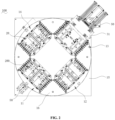
Fig. 1 is a schematic structural view of a pre-stacking device according to one or more embodiments; -
Fig. 2 is a top view of a pre-stacking device according to one or more embodiments; -
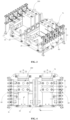
Fig. 3 is a schematic structural view of a tray in a pre-stacking device according to one or more embodiments; -
Fig. 4 is a top view of a tray in a pre-stacking device according to one or more embodiments; -
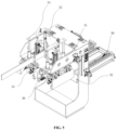
Fig. 5 is a schematic structural perspective view illustrating cooperation between a first clamping assembly and a pushing assembly in a pre-stacking device according to one or more embodiments; -
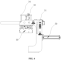
Fig. 6 is a schematic structural view illustrating cooperation between a first clamping assembly and a pushing assembly in a pre-stacking device according to one or more embodiments; -
Fig. 7 is a partial enlarged view ofFig. 5 ; and -
Fig. 8 is a schematic flowchart of a pre-stacking method according to one or more embodiments. - 100. pre-stacking device; 10. mounting seat; 20. tray; 30. first clamping assembly; 40. second clamping assembly; 50. pushing assembly; 11. first station; 12. fourth station; 13. second station; 14. third station; 15. base; 16. support member; 41. first clamping member; 42. second clamping member; 31. main body; 32. first driving member; 33. limiting assembly; 34. lifting member; 51. abutting member; 52. pushing member; 331. adjustment member; 332. pressing member; 3321. connecting portion; 3322. rolling portion; 50. positioning assembly; 60. detection assembly; 200. battery cell; L1. thickness direction; L2. width direction; L3. height direction.
- Examples of the technical solutions of the present application will be described in detail below in conjunction with the drawings. The following embodiments are merely intended to illustrate the technical solutions of the present application more clearly, and therefore are only intended as examples and shall not be intended to limit the scope of protection of the present application.
- Unless otherwise defined, all technical and scientific terms used herein have the same meaning as commonly understood by those skilled in the art belonging to the technical field of the present application; the terms used herein are intended only for the purpose of describing specific embodiments and are not intended to limit the present application; the terms "including" and "having" and any variations thereof in the specification and the claims of the present application and in the description of drawings above are intended to cover non-exclusive inclusion.
- In the description of the embodiments of the present application, the technical terms "first", "second", and the like are used only to distinguish between different objects, and are not to be understood as indicating or implying relative importance or implicitly specifying the number, particular order, or primary and secondary relation of the technical features indicated. In the description of the embodiments of the present application, the meaning of "a plurality of" is two or more, unless otherwise explicitly and specifically defined.
- Reference herein to "an embodiment" means that a particular feature, structure, or characteristic described in connection with the embodiment can be included in at least one embodiment of the present application. The appearance of this phrase in various places in the specification does not necessarily refer to the same embodiment, nor is it a separate or alternative embodiment that is mutually exclusive with other embodiments. It is explicitly and implicitly understood by those skilled in the art that the embodiments described herein may be combined with other embodiments.
- In the description of the embodiments of the present application, the term "and/or" is only an associative relationship for describing associated objects, indicating that there may be three relationships, for example A and/or B may represent three situations: A alone, both A and B, and B alone. In addition, the character "/" herein generally means that the associated objects before and after it are in an "or" relationship.
- In the description of the embodiments of the present application, the term "a plurality of" refers to two or more (including two), and similarly, "multiple groups" refers to two or more (including two) groups, and "multiple sheets" refers to two or more (including two) sheets.
- In the description of the embodiments of the present application, the orientation or position relationship indicated by the technical terms "central," "longitudinal," "transverse," "length," "width," "thickness," "upper," "lower," "front," "back," "left," "right," "vertical," "horizontal," "top," "bottom," "inner," "outer," "clockwise," "counterclockwise," "axial", "radial", "circumferential", etc. are based on the orientation or position relationship shown in the drawings and are intended to facilitate the description of the embodiments of the present application and simplify the description only, rather than indicating or implying that the device or element referred to must have a particular orientation or be constructed and operated in a particular orientation, and therefore are not to be interpreted as limitations on the embodiments of the present application.
- In the description of the embodiments of the present application, unless otherwise expressly specified and limited, the technical terms "mount," "join," "connect," "fix," etc. should be understood in a broad sense, such as, a fixed connection, a detachable connection, or an integral connection; a mechanical connection, or an electrical connection; a direct connection, an indirect connection through an intermediate medium, an internal connection of two elements, or interaction between two elements. For those of ordinary skill in the art, the specific meanings of the above terms in the embodiments of the present application can be understood according to specific situations.
- At present, from the perspective of the development of the market situation, power batteries are more and more widely used. The power batteries are used in energy storage power source systems such as hydraulic, thermal, wind and solar power stations as well as in electric vehicles such as electric bicycles, electric motorcycles and electric cars, and other fields. With the continuous expansion of the application field of the power batteries, the market demand is also constantly expanding.
- A battery cell is the smallest unit that makes up a battery. Specifically, multiple battery cells can be connected in series, in parallel or in parallel-series connection to form a battery module, and then one or more battery modules are connected and assembled into a battery. Of course, multiple battery cells can also be directly assembled into a battery. The parallel-series connection means that the multiple battery cells are connected in both series and parallel.
- In the process of forming a battery module or battery from battery cells, it is usually necessary to apply adhesive on the surface of the battery cells, and then pre-stack multiple battery cells along the thickness direction so that the battery cells can be tightly attached to each other and then bonded and fixed to each other through the adhesive tape on the surfaces of the adjacent battery cells.
- However, in the current pre-stacking process, the pre-stacking procedure is complex and poor in stability, which will not only cause multiple battery cells to fall at the same time, but also greatly reduce the stacking efficiency, affecting the efficiency of the battery cell pre-stacking process, and even affecting the structural stability of the battery module or battery formed by assembly of the battery cells.
- Based on the above considerations, in order to solve the problem of low pre-stacking efficiency and poor stability of the current battery cell pre-stacking process, one or more embodiments of the present application provide a pre-stacking device, the pre-stacking method enabling the batteries to be removed after being stably pre-stacked so as to realize automatic and stable stacking, thereby improving production efficiency and reducing costs.
- Referring to
Figs. 1 to 4 , the present application provides apre-stacking device 100. Thepre-stacking device 100 includes a mountingseat 10, atray 20, and a pushingassembly 50. The mountingseat 10 includes at least one station, thetray 20 is arranged on the mountingseat 10, thetray 20 is used to carry at least twobattery cells 200 arranged along their thickness direction L1, and the pushingassembly 50 is movably arranged at one of the stations along the thickness direction L2 of thebattery cells 200. The pushingassembly 50 is used to drive thebattery cells 200 on thetray 20 to move along the thickness direction L2 of thebattery cells 200 on the corresponding station, so that every twoadjacent battery cells 200 are attached to each other. - The mounting
seat 10 refers to a structure that can provide a basis for installation of thetray 20 and the pushingassembly 50. Thetray 20 refers to a structure provided on the mountingseat 10 that can provide space for supporting and stacking at least twobattery cells 200.Multiple battery cells 200 can be clamped along the thickness direction L1 of thebattery cells 200 and placed on thetray 20 by an external manipulator or a handling device. At this time, since thebattery cells 200 are not subject to any force, they are loosely arranged and have not yet formed a tight stack. - Then, the movement of the
tray 20 is controlled so that thetray 20 moves to the station where the pushingassembly 50 is located. Thebattery cells 200 are generally stacked with the side where the terminal posts are provided facing upwards. At this time, the height direction L3 of thebattery cells 200 refers to the direction from one side surface provided with the terminal posts to the opposite side surface, the width direction L2 of thebattery cells 200 refers to the direction perpendicular to the height direction L3 of thebattery cells 200 and parallel to the direction of the large surface of thebattery cells 200, and the thickness direction L1 of thebattery cells 200 refers to the direction perpendicular to the large surface of thebattery cells 200. The large surface of thebattery cells 200 generally refers to the side surface of thebattery cells 200 with the largest area. - When the pushing
assembly 50 exerts pressure on thebattery cells 200, the pushingassembly 50 first contacts the large surface of one of thebattery cells 200, and then continues to push along the thickness direction L1 ofmultiple battery cells 200 to keep the friction between thebattery cells 200 and their supporting surfaces in balance, so that the large surfaces of themultiple battery cells 200 are in direct contact with each other, and balance is kept betweenvarious battery cells 200, so as to complete stable pre-stacking and prevent falling of thebattery cells 200. - When the pushing
assembly 50 pushes thebattery cells 200, it may be in direct surface-to-surface contact with the large surface of thebattery cells 200, or may form a spherical structure to abut against the large surface of thebattery cells 200. It is to be noted that the contact of the pushingassembly 50 with thebattery cells 200 and the force it exerts during the pre-stacking process must ensure that thebattery cells 200 are not damaged. - With the
pre-stacking device 100 provided by the present application, the close stacking ofmultiple battery cells 200 along their thickness direction L2 can be realized through the pushing operation by the pushingassembly 50 when thetray 20 and thebattery cells 200 on the tray move to the station where the pushingassembly 50 is located. - It can be understood that after the stacking is completed, the
tray 20 and thebattery cells 200 stacked thereon can be removed for the next step of operation. - In some embodiments, referring to
Figs. 1 to 4 , the stations of the mountingseat 10 include afirst station 11, asecond station 13 and athird station 14 arranged at intervals in the circumferential direction, and thetray 20 is configured to rotate between thefirst station 11, thesecond station 13 and thethird station 14. - The
first station 11 is used for loading thebattery cells 200 on thetray 20, the pushingassembly 50 is arranged on thesecond station 13, and thethird station 14 is used for unloading thebattery cells 200 that have been attached to each other off thetray 20. - The
second station 13 refers to the station on the mountingseat 10 for pressing and stackingmultiple battery cells 200. Specifically, thebattery cells 200 are moved from the previous process to thesecond station 13, and themultiple battery cells 200 are sequentially stacked along the thickness direction L1 at thesecond station 13 to realize pre-stacking of thebattery cells 200 so that themultiple battery cells 200 can be closely attached to each other. - The
first station 11, thesecond station 13 and thethird station 14 can swap with each other through the rotation or movement or other motions of the mountingseat 10, and thetray 20 can move from thefirst station 11 to thesecond station 13 and then move to thethird station 14, and then return from thethird station 14 to thefirst station 11. The process in which thetray 20 rotates from thefirst station 11 in a circle to return to thefirst station 11 is called one pre-stacking process. An external manipulator or handling device can place thebattery cells 200 on thetray 20 at thefirst station 11, and can also remove thebattery cells 200 from thethird station 13. - After the
multiple battery cells 200 are loosely placed on thefirst station 11 along their thickness direction L1, the movement of thetray 20 is controlled so that thetray 20 moves from thefirst station 11 to thesecond station 13. When thetray 20 is located at thesecond station 13, the pushingassembly 50 on thesecond station 13 exerts pressure on thebattery cells 200 to complete the pre-stacking and prevent thebattery cells 200 from falling. - Then, the
tray 20 finished with pre-stacking and thebattery cells 200 thereon are controlled to move to thethird station 14. At this time, themultiple battery cells 200 that have been stacked on thetray 20 can be removed by an external device to proceed to the next step of the process. After thebattery cells 200 are removed from thetray 20 at thethird station 14, thetray 20 can be controlled to continue to move back to thefirst station 11 of the device for the next pre-stacking process. - As such, with the
pre-stacking device 100 of the present application, a simple multi-station stacking procedure is formed to realize the loading, stacking, and unloading process of thebattery cells 200. The placement and removal ofbattery cells 200 on different stations do not affect each other, and pre-stacking is divided into multiple steps that proceed in a cycle to realize automatic pre-stacking, so that the efficiency of pre-stacking of thebattery cells 200 is improved, the pre-stacking stability is good, and production is conducted on different stations synchronously without affecting each other, thereby improving production efficiency. - It can be understood that the stations on the mounting
seat 10 may also include stations in addition to thefirst station 11, thesecond station 13 and thethird station 14, which is not limited in the present application. - In some embodiments, referring to
Figs. 1 and2 , the mountingseat 10 includes abase 15 and asupport member 16 rotatably arranged on thebase 15, thebase 15 has afirst station 11, asecond station 13 and athird station 14 arranged at intervals along the circumferential direction thereof, andmultiple trays 20 are provided on thesupport member 16 and rotate along with thesupport member 16. When one of thetrays 20 moves to thefirst station 11, there is atray 20 on each of thesecond station 13 and thethird station 14. - Specifically, the
support member 16 may be provided as a rotary table, and according to the positional relationship between thefirst station 11, thesecond station 13 and thethird station 14 provided on thebase 15, threetrays 20 are correspondingly arranged at intervals along the circumferential direction of thesupport member 16. When thesupport member 16 brings along the threetrays 20 thereon to rotate so that one of thetrays 20 arrives at thefirst station 11, the other twotrays 20 are located at thesecond station 13 and thethird station 14 respectively. - As such, each
tray 20 can load at thefirst station 11, pre-stack at thesecond station 13, and unload at thethird station 14, andmultiple trays 20 can be engaged in production synchronously at different stations at the same time. When thetray 20 at thefirst station 11 is loading, thetray 20 at thefourth station 12 is pre-stacking, and thetray 20 at thesecond station 13 is unloading, which goes round and round without affecting each other, thereby improving production efficiency. - In some embodiments, referring to
Figs. 1 and2 , the mountingseat 10 also has afourth station 12, and thefourth station 12 is arranged at an interval between thefirst station 11 and thesecond station 13. When thetray 20 is located at thefourth station 12, at least twobattery cells 200 are pre-stacked on thetray 20 along their thickness direction L1. - The
battery cells 200 may be arranged in different directions. Eachbattery cell 200 has two large surfaces. When the two large surfaces are oriented differently, the positive terminal post and the negative terminal post of thebattery cells 200 are placed in different positions, so that twobattery cells 200 that serve as a formula cell for each other are formed. That is, for twobattery cells 200 that serve as a formula cell for each other at this time, assuming that the positive terminal post of one of thebattery cells 200 is on the left and the negative terminal post is on the right, then theother battery cell 200 is equivalent to the onebattery cell 200 rotated around the height direction L3 by 180 degrees, so as to be placed in such a manner that the positive terminal post is on the right and the negative terminal post is on the left. - After the pre-stacking process is completed, the
battery cells 200 need to be moved to a different position. Therefore, in order to improve the efficiency of subsequent assembly, a first area and a second area can be formed on thetray 20. When thetray 20 is at thefirst station 11, one of thebattery cells 200 that serve as a formula cell for each other is placed in the first area, and when thetray 20 is at thefourth station 12, the other one of thebattery cells 200 that serve as a formula cell for each other is placed in the second area. After thetray 20 moves to thesecond station 13, thebattery cells 200 are pre-stacked according to their polarities, so as to ensure that when thetray 20 moves to thethird station 14, they can be picked up by the operator as needed. - Of course, it is also possible to load the
battery cells 200 in the same placement direction in which the positive terminal posts and the negative terminal posts are arranged in exactly the same direction at thefirst station 11 and thefourth station 12. As such, multiple loadings can be performed while avoiding falling of thebattery cells 200 due to excessive loading at one time. - In some embodiments, referring to
Figs. 1 and2 , thepre-stacking device 100 further includes apositioning assembly 50 arranged at thefirst station 11 to fix thetray 20 on thefirst station 11. - The
positioning assembly 50 can be a combination of a driving structure and a positioning protrusion, and a groove is provided at the corresponding position of thesupport member 16 or thetray 20. When thesupport member 16 brings along thetrays 20 thereon to rotate, one of thetrays 20 moves to thefirst station 11. At this time, the driving structure drives the positioning protrusion to extend and fit into the groove, and thesupport member 16 is stopped. At this time, thetray 20 is stably fixed on thefirst station 11 for loading. - After the loading is completed, the driving structure can also drive the positioning protrusion to retract. At this time, the
support member 16 continues to rotate until thetray 20 for which loading at thefirst station 11 has just been completed moves to thefourth station 12, and at this time, anothertray 20 moves to thefirst station 11 for loading, while thetray 20 at thefourth station 12 is undergoing loading at thefourth station 12, and so on. - Further, a sensing device may also be provided on the
tray 20 and thepositioning assembly 50, and when thepositioning assembly 50 senses thetray 20, the positioning protrusion is immediately driven to extend and stop thesupport member 16. - As such, in the present application, by providing the
positioning assembly 50, automatic positioning of thefirst station 11 can be realized and thetray 20 can be automatically stopped for operation at various stations. - In some embodiments, referring to
Figs. 1 ,2 ,5 and6 , thepre-stacking device 100 further includes afirst clamping assembly 30 configured to be movably arranged on the mountingseat 10 along the height direction L3 of thebattery cells 200. Thefirst clamping assembly 30 can clamp thebattery cells 200 on thetray 20 along the width direction L2 of thebattery cells 200 when thetray 20 moves to thesecond station 13. The width direction L2 of thebattery cells 200 is perpendicular to the thickness direction L1. - Specifically, when the
tray 20 moves to thesecond station 13, thefirst clamping assembly 30 can descend along the height direction L3 of thebattery cells 200, the height direction L3 of thebattery cells 200 being perpendicular to the width direction L2 and the thickness direction L1 of thebattery cells 200, until thefirst clamping assembly 30 can smoothly clamp the upper side of thebattery cells 200 along the width direction L2 of thebattery cells 200, so that thebattery cells 200 can be pressed by the pushingassembly 50. - When the
tray 20 has not yet moved to thesecond station 13, thefirst clamping assembly 30 does not need to clamp thebattery cells 200, then at this time, thefirst clamping assembly 30 rises along the height direction L3 of thebattery cells 200, away from thesupport member 16, until the movement of thebattery cells 200 on thetray 20 along with thetray 20 between the stations is not affected. - Through the movable arrangement of the
first clamping assembly 30 in the height direction L3 of thebattery cells 200, thefirst clamping assembly 30 can smoothly realize clamping of thebattery cells 200 when thebattery cells 200 move to thesecond station 13, thereby ensuring the effectiveness of pushing by the pushingassembly 50. Moreover, thefirst clamping assembly 30 does not affect the movement of thebattery cells 200 along with thetray 20 in other cases, and the movement of thebattery cells 200 among multiple stations can be smoothly realized. - In some embodiments, referring to
Figs. 3 and 4 , thepre-stacking device 100 further includes asecond clamping assembly 40 arranged on thetray 20 to clamp thebattery cells 200 on thetray 20 along the width direction L2 of thebattery cells 200. Thefirst clamping assembly 30 is arranged at an interval from thesecond clamping assembly 40 along the height direction L3 of thebattery cells 200. - When the
battery cell 200 is placed on thetray 20, thebattery cell 200 on thetray 20 is first clamped by thesecond clamping assembly 40 along the width direction L2 of theoriginal battery cell 200, and then in the whole pre-stacking process, clamping of thebattery cell 200 is maintained to prevent thebattery cell 200 from falling after being placed on thetray 20. - When the
tray 20 is moved to thesecond station 13, thefirst clamping assembly 30 is arranged at an interval from thesecond clamping assembly 40 along the height direction L3 of thebattery cell 200 at thesecond station 13. Thus, thefirst clamping assembly 30 can clamp thebattery cell 200 again along the width direction L2 of thebattery cell 200 at thesecond station 13. At this time, thesecond clamping assembly 40 and thefirst clamping assembly 30 clamp thebattery cell 200 at different positions in the height of thebattery cell 200 respectively along its height direction L3, such as at the bottom end and the middle, or the middle and the top end. - The
second clamping assembly 40 and thefirst clamping assembly 30 can be spaced apart from each other along the height direction L3 of thebattery cell 200 and can clamp and fix the opposite ends of thebattery cell 200 in the height direction L3, so that the friction between thebattery cell 200 and the supporting surface thereof can be kept in balance, thereby making the pre-stacking process of thebattery cells 200 smoother, reducing the probability of thebattery cells 200 falling during the pre-stacking process, and making stacking of thebattery cells 200 more stable. - In some embodiments, both the
first clamping assembly 30 and thesecond clamping assembly 40 include afirst clamping member 41 and asecond clamping member 42 respectively arranged on two sides of thetray 20 along the width direction L2 of thebattery cell 200, and at least one of the first clampingmember 41 and thesecond clamping member 42 is configured to be movably arranged along the width direction L2 of thebattery cell 200. - Specifically, the first clamping
member 41 and thesecond clamping member 42 in thesecond clamping assembly 40 can be respectively arranged on two sides of thetray 20 via telescopic cylinders, so that the first clampingmember 41 and thesecond clamping member 42 can approach or move away from each other along the width direction L2 of thebattery cell 200. When thebattery cell 200 is placed on thetray 20, the first clampingmember 41 and thesecond clamping member 42 approach each other and clamp thebattery cell 200. When thebattery cell 200 needs to be removed from thetray 20, the first clampingmember 41 and thesecond clamping member 42 move away from each other. - By providing the first clamping
member 41 and thesecond clamping member 42, thebattery cell 200 can be smoothly clamped, so that thebattery cell 200 can be stably placed on thetray 20, and thebattery cell 200 can be kept in balance during pressing. - Moreover, the first clamping
member 41 and thesecond clamping member 42 are provided so that thefirst clamping assembly 30 and thesecond clamping assembly 40 are adapted to clamp a variety ofbattery cells 200 of different widths. As such, pre-stacking ofbattery cells 200 of different sizes can be realized by the same stackingdevice 100, which facilitates model exchange (different models of the battery cells 200). - In some embodiments, referring to
Figs. 5 and6 , thefirst clamping assembly 30 further includes amain body 31 and a first drivingmember 32, and the first drivingmember 32 is connected between themain body 31 and the mountingseat 10 to drive themain body 31 to move along the height direction L3 of thebattery cell 200. Thefirst clamping member 41 and thesecond clamping member 42 in thefirst clamping assembly 30 are arranged on themain body 31, and the pushingassembly 50 is movably connected to themain body 31 along the thickness direction L1 of thebattery cell 200. - Specifically, the
main body 31 can provide basis for installation of the first drivingmember 32, the pushingassembly 50, the first clampingmember 41 and thesecond clamping member 42. The first drivingmember 32 may be, without limitation, provided as a press-down cylinder for driving themain body 31 and bringing along the first clampingmember 41 and thesecond clamping member 42 on themain body 31 to move along the height direction L3 of thebattery cell 200. The pushingassembly 50 can move on themain body 31 to approach or move away from thebattery cell 200 on thetray 20. - By providing the
main body 31 and the first drivingmember 32, the first clampingmember 41 and thesecond clamping member 42 can be brought along to move along the height direction L3 of thebattery cell 200, so as to clamp and fix thebattery cell 200 during pressing and avoid thebattery cell 200 when it does not need to be pressed. - Further, the
first clamping assembly 30 also includes a liftingmember 34, the first drivingmember 32 is driving-connected with the liftingmember 34, and the liftingmember 34 passes through themain body 31 and is connected with thefirst clamping assembly 30. When the first drivingmember 32 drives the liftingmember 34 to move up and down, thefirst clamping assembly 30 is brought along to move up and down. - With such an arrangement, the first driving
member 32 and thefirst clamping assembly 30 can be arranged on opposite sides of themain body 31, thereby making reasonable use of the assembly space. - In some embodiments, the
first clamping assembly 30 further includes a limitingassembly 33 arranged on themain body 31 and located between the first clampingmember 41 and thesecond clamping member 42, and the limitingassembly 33 is used to press thebattery cells 200 on thetray 20 along the height direction L3 of thebattery cells 200. - When the first clamping
member 41 and thesecond clamping member 42 clamp an upper side of thebattery cell 200 along the width direction L2 of thebattery cell 200, the limitingassembly 33 is located between the first clampingmember 41 and thesecond clamping member 42 and can press thebattery cell 200 downwards, so that thebattery cell 200 can be stably supported on the support surface of thetray 20. Thus, thebattery cell 200 can be more stable during the pre-stacking process. - In some embodiments, referring to
Figs. 5 to 7 , the limitingassembly 33 includes anadjustment member 331 and apressing member 332, theadjustment member 331 is telescopically connected between themain body 31 and thepressing member 332 along the height direction L3 of thebattery cells 200, and thepressing member 332 is used to press thebattery cells 200 on thetray 20 along the height direction L3 of thebattery cells 200. - Specifically, the
adjustment member 331 may be, without limitation, provided as a spring that is elastically connected between themain body 31 and thepressing member 332, so that thepressing member 332 can be elastically pressed against thebattery cell 200. - Further,
multiple adjustment members 331 and multiple pressingmembers 332 can be provided, and theadjustment members 331 and thepressing members 332 are provided in one-to-one correspondence. - It should be noted that a terminal post is protruded from each
battery cell 200, and due to mechanical errors, there may be a certain difference between the heights of the terminal posts ofdifferent battery cells 200. Thus, each of thepressing members 332 and theadjustment members 331 can be correspondingly pressed against a terminal post of abattery cell 200. Each pressingmember 332 can be adaptively pressed against the terminal post of thecorresponding battery cell 200 through extension and retraction of theadjustment member 331, so that the pressing effect of thepressing member 332 on eachbattery cell 200 is more stable. - By providing the
adjustment member 331 and thepressing member 332, thebattery cell 200 can be flexibly and stably pressed against thetray 20, so that thebattery cell 200 can be kept in balance during the process of pushing of thebattery cell 200. - In some embodiments, referring to
Figs. 5 to 7 , the pressingmember 332 includes a connectingportion 3321 and a rollingportion 3322, the connectingportion 3321 is connected to theadjustment member 331, and the rollingportion 3322 is rollably arranged on the connectingportion 3321 along the thickness direction L1 of thebattery cell 200, and is used to be rollably pressed against thebattery cells 200 on thetray 20 along the height direction L3 of thebattery cells 200. - When there are multiple pressing
members 332, eachpressing member 332 includes a connectingportion 3321 and a rollingportion 3322. Specifically, the rollingportion 3322 can be, without limitation, provided as a roller that is rollably arranged on the connectingportion 3321. When thepressing member 332 is pressed against thebattery cells 200, the pushingassembly 50 exerts pressure on thebattery cells 200 along the thickness direction L1 of thebattery cells 200, so that thebattery cells 200 approach and are attached to each other along the thickness direction L1. - At the same time, when the
battery cell 200 is displaced along the thickness direction L1 under the pushing force, the rollingportion 3322 can rollably press thebattery cell 200, so that the pressing on thebattery cell 200 is more stable and does not affect movement of thebattery cell 200 in the thickness direction L1. - By providing the rolling
portion 3322, rollable pressing can be realized between thepressing member 332 and thebattery cells 200, and when thebattery cells 200 move closer to each other along the thickness direction L1, the pressing force can be continuously applied, so that the pressing process is more stable. - In some embodiments, referring to
Figs. 3 to 5 , the pushingassembly 50 includes an abuttingmember 51 and a pushingmember 52, the abuttingmember 51 is arranged on thetray 20, the pushingmember 52 is movably arranged on the mountingseat 10 along the thickness direction L1 of thebattery cell 200, and the abuttingmember 51 and the pushingmember 52 are respectively arranged on two sides of thetray 20 along the thickness direction L1 of thebattery cell 200, and the pushingmember 52 is configured to be able to push thebattery cells 200 on thetray 20 along the thickness direction L1 of thebattery cells 200 to abut against the abuttingmember 51. - Specifically, the abutting
member 51 is a baffle arranged on thetray 20. When thebattery cell 200 moves to thesecond station 13 along with thetray 20, the pushingmember 52 and the abuttingmember 51 are respectively located on two sides of thebattery cell 200 along the thickness direction L1 of thebattery cell 200. The pushingassembly 52 moves along the thickness direction L1 of thebattery cells 200, and exerts a pushing force on thebattery cells 200 along the thickness direction L1 of thebattery cells 200, so thatmultiple battery cells 200 can be closely attached to each other. - Further, the pushing
member 52 may be, without limitation, provided as a pressurization cylinder. When thebattery cells 200 are arranged on thetray 20 along the thickness direction L1, the pushingassembly 52 extends and exerts a pushing force on the large surface of thebattery cells 200, so that themultiple battery cells 200 can be closely attached to each other. - Through cooperation between the abutting
member 51 and the pushingmember 52, pre-stacking ofmultiple battery cells 200 can be smoothly realized, so that thebattery cells 200 are closely attached along the thickness direction L1 thereof so as to facilitate subsequent assembly. - In some embodiments, referring to
Figs. 3 to 4 , thepre-stacking device 100 further includes adetection assembly 60 arranged on thetray 20. Thedetection assembly 60 is configured to detect whether there is abattery cell 200 on thetray 20. - The
detection assembly 60 may be an infrared detection structure or the like. It can be understood that if nobattery cell 200 is placed on thetray 20, and if the pushingassembly 52 is still pushing in the same procedure at this time, it may possibly collide directly with the abuttingmember 51. - By providing the
detection assembly 60, the pushingassembly 50 can be intelligently controlled according to the detection structure of thedetection assembly 60, so as to avoid safety accidents. - Based on the same concept as the above-mentioned
pre-stacking device 100, the present application further provides a battery processing equipment including the above-mentionedpre-stacking device 100. - Referring to
Fig. 8 , based on the same concept as the above-mentionedpre-stacking device 100, according to one or more embodiments, the present application provides a pre-stacking method including the following steps. - S10: A
tray 20 is controlled to move to afirst station 11 of a mountingseat 10, and at least twobattery cells 200 are placed on thetray 20 along their thickness direction L1. - S30: The
tray 20 is controlled to move to asecond station 13 of the mountingseat 10, and a pushingassembly 50 is controlled to drive thebattery cells 200 on thetray 20 to move along the thickness direction L1 of thebattery cells 200, so that every twoadjacent battery cells 200 are attached to each other. - S40: The
tray 20 is controlled to move to athird station 14 of the mountingseat 10, and thebattery cells 200 are removed from thetray 20. - The
first station 11, thesecond station 13 and thethird station 14 are arranged at intervals in the circumferential direction of the mountingseat 10. - Specifically, the specific structural configurations of the mounting
seat 10, thetray 20 and the pushingassembly 50 have been described in detail above, and description thereof will not be repeated here. - As such, according to the present application, with the method described above, a simple multi-station stacking procedure is formed to realize the loading, stacking, and unloading process of the
battery cells 200. The placement and removal ofbattery cells 200 on different stations do not affect each other, and pre-stacking is divided into multiple steps that proceed in a cycle to realize automatic pre-stacking, so that the efficiency of pre-stacking of thebattery cells 200 is improved, the pre-stacking stability is good, and production is conducted on different stations synchronously without affecting each other, thereby improving production efficiency. - In some embodiments, referring to
Fig. 8 , after thetray 20 is controlled to move to thefirst station 11 of the mountingseat 10 in step S10, the method further includes the following step. - S20: The
tray 20 is controlled to move to afourth station 12 of the mountingseat 10, and at least twobattery cells 200 are placed on thetray 20 along their thickness direction L1. - The
fourth station 12 is arranged at an interval between thefirst station 11 and thesecond station 13 along the circumferential direction. - With reference to the foregoing description, the
pre-stacking device 100 of the present application can not only realize simultaneous stacking and unloading of the formula cells, but also realize multiple loadings of thebattery cells 200 in the same placement direction, thereby avoiding falling of thebattery cells 200 due to excessive loading at one time. - In some embodiments, after at least two
battery cells 200 are placed on thetray 20 along their thickness direction L1 in step S10, the method further includes the following step. - S50: The
battery cells 200 on thetray 20 are clamped along the width direction L2 of thebattery cells 200, the width direction L2 of thebattery cells 200 being perpendicular to the thickness direction L1 of thebattery cells 200. - Specifically, the
battery cells 200 can be clamped along the width direction L2 by the provided first clampingassembly 30. The specific structure of thefirst clamping assembly 30 has been described in detail above and description thereof will not be repeated here. - Further, steps S30 and S50 can be performed concurrently, or the pushing in step S30 can be performed after the clamping operation is completed in step S50. As such, clamping of the
battery cell 200 can be smoothly realized when thebattery cell 200 moves to thesecond station 13, thereby ensuring the effectiveness of pushing by the pushingassembly 50. Moreover, thefirst clamping assembly 30 does not affect the movement of thebattery cell 200 along with thetray 20 in other cases, and the movement of thebattery cell 200 among multiple stations can be smoothly realized. - According to one or more embodiments, first,
multiple battery cells 200 are sequentially moved to thetray 20 of thefirst station 11 by an external manipulator, and the lower side of eachbattery cell 200 on thetray 20 is clamped by thesecond clamping assembly 40 so that it is stably placed on thetray 20. Thesupport member 16 is rotated, and thetray 20 and thebattery cells 200 thereon are moved to thefourth station 12, and the formula cells are placed on thetray 20 by the external manipulator. - As the
support member 16 continues to be rotated, when thetray 20 thereof rotates to thesecond station 13, thefirst clamping assembly 30 is controlled to descend, and the upper side of thebattery cell 200 is clamped and fixed by thefirst clamping assembly 30. Meanwhile, under the action of theadjustment member 331, the pressingmember 332 is adaptively pressed against the terminal post of thecorresponding battery cell 200. - Once the pressing is stabilized, the pushing
member 52 is controlled to move toward thebattery cell 200 to exert a pushing force on the large surface of thebattery cell 200. Under the action of the pushing force, themultiple battery cells 200 approach each other along the thickness direction L1 and abut against the abuttingmember 51 until themultiple battery cells 200 are closely attached to each other. At this point, the pre-stacking of thebattery cells 200 on thetray 20 is completed. Thesupport member 16 continues to be rotated and moved to thethird station 14, and removal is done by the manipulator, while thebattery cells 200 on thenext tray 20 are being pushed, and so on. - Finally, it should be noted that the above embodiments are merely used for illustrating rather than limiting the technical solutions of the present application. Although the present application has been described in detail with reference to the above various embodiments, those of ordinary skill in the art should understand that the technical solutions specified in the above various embodiments can still be modified, or some or all of the technical features therein can be equivalently substituted; and such modifications or substitutions do not make the essence of the corresponding technical solutions depart from the scope of the technical solutions of the various embodiments of the present application, but rather shall fall within the scope of the claims and the specification of the present application. In particular, the technical features mentioned in the various embodiments can be combined in any manner as long as there is no structural conflict. The present application is not limited to the specific embodiments disclosed herein, but rather includes all technical solutions falling within the scope of the claims.
Claims (18)
- A pre-stacking device, comprising:a mounting seat comprising at least one station;a tray arranged on the mounting seat to carry at least two battery cells arranged along the thickness direction thereof; anda pushing assembly movably arranged along the thickness direction of the battery cells on one of the stations;wherein the pushing assembly is used to drive the battery cells on the tray to move along the thickness direction of the battery cells on the corresponding station, so that every two adjacent battery cells are attached to each other.
- The pre-stacking device according to claim 1, wherein the stations comprise a first station, a second station and a third station arranged at intervals in the circumferential direction, and the tray is configured to rotate between the first station, the second station and the third station; and
the first station is used for loading the battery cells on the tray, the pushing assembly is arranged on the second station, and the third station is used for unloading the battery cells that have been attached to each other off the tray. - The pre-stacking device according to claim 2, wherein the mounting seat comprises a base and a support member rotatably arranged on the base, the base has the first station, the second station and the third station arranged at intervals along the circumferential direction thereof, and multiple trays are arranged on the support member and rotate along with the support member; and
when one of the trays moves to the first station, there is one tray on each of the second station and the third station. - The pre-stacking device according to any one of claim 2 or 3, wherein the mounting seat further has a fourth station arranged at an interval between the first station and the second station; and
the fourth station is used for loading the battery cells. - The pre-stacking device according to any one of claims 2-4, further comprising a positioning assembly arranged at the first station, wherein
the positioning assembly is used to fix the tray to the first station. - The pre-stacking device according to any one of claims 2-5, further comprising a first clamping assembly configured to be movably arranged along the height direction of the battery cells on the mounting seat; wherein
the first clamping assembly can clamp the battery cells on the tray along the width direction of the battery cells when the tray moves to the second station, the width direction of the battery cells being perpendicular to the thickness direction. - The pre-stacking device according to claim 6, further comprising a second clamping assembly arranged on the tray to clamp the battery cells on the tray along the width direction of the battery cells.
the first clamping assembly is arranged at an interval from the second clamping assembly along the height direction of the battery cells, the height direction of the battery cells being perpendicular to both the width direction and the thickness direction. - The pre-stacking device according to claim 7, wherein both the first clamping assembly and the second clamping assembly comprise a first clamping member and a second clamping member respectively arranged on two sides of the tray along the width direction of the battery cells, and at least one of the first clamping member and the second clamping member is configured to be movably arranged along the width direction of the battery cells.
- The pre-stacking device according to claim 6, wherein the first clamping assembly further comprises a main body and a first driving member connected between the main body and the mounting seat to drive the main body to move along the height direction of the battery cells; and
wherein the first clamping member and the second clamping member in the first clamping assembly are arranged on the main body, and the pushing assembly is movably connected with the main body along the thickness direction of the battery cells. - The pre-stacking device according to claim 9, wherein the first clamping assembly further comprises a limiting assembly arranged on the main body and located between the first clamping member and the second clamping member, and the limiting assembly is used to press the battery cells on the tray along the height direction of the battery cells.
- The pre-stacking device according to claim 10, wherein the limiting assembly comprises an adjustment member and a pressing member, the adjustment member is telescopically connected between the main body and the pressing member along the height direction of the battery cells, and the pressing member is used to press the battery cells on the tray along the height direction of the battery cells.
- The pre-stacking device according to claim 11, wherein the pressing member comprises a connecting portion and a rolling portion, the connecting portion is connected to the adjustment member, and the rolling portion is rollably arranged on the connecting portion along the thickness direction of the battery cells to be rollably pressed against the battery cells on the tray along the height direction of the battery cells.
- The pre-stacking device according to any one of claims 1-14, wherein the pushing assembly comprises an abutting member and a pushing member, the abutting member is arranged on the tray, the pushing member is movably arranged on the mounting seat along the thickness direction L1 of the battery cells, and the abutting member and the pushing member are respectively arranged on two sides of the tray along the thickness direction L1 of the battery cells; and
the pushing member is configured to be able to push the battery cells on the tray along the thickness direction L1 of the battery cells against the abutting member. - The pre-stacking device according to any one of claims 1-13, further comprising a detection assembly arranged on the tray, wherein
the detection assembly is used to detect whether there is the battery cell on the tray. - A battery processing equipment comprising a pre-stacking device according to any one of claims 1-14.
- A pre-staking method, comprising the steps of:controlling a tray to move to a first station of the mounting seat, and placing at least two battery cells on the tray along their thickness direction;controlling the tray to move to a second station of the mounting seat, and controlling a pushing assembly to drive the battery cells on the tray along the thickness direction of the battery cells to move, so that every two adjacent battery cells are attached to each other; andcontrolling the tray to move to a third station of the mounting seat, and removing the battery cells from the tray;wherein the first station, the second station and the third station are arranged at intervals in the circumferential direction of the mounting seat.
- The pre-stacking method according to claim 15, further comprising, after controlling the tray to move to the first station of the mounting base, the step of:
controlling the tray to move to a fourth station of the mounting seat, and placing at least two battery cells on the tray along their thickness direction; wherein the fourth station is arranged at an interval between the first station and the second station along the circumferential direction. - The pre-stacking method according to claim 15, further comprising, after controlling a tray to move to a first station of the mounting seat and placing at least two battery cells on the tray along their thickness direction, the step of:
clamping the battery cells on the tray along the width direction of the battery cells, the width direction of the battery cells being perpendicular to the thickness direction of the battery cells.
Applications Claiming Priority (1)
| Application Number | Priority Date | Filing Date | Title |
|---|---|---|---|
| PCT/CN2023/101791 WO2024259655A1 (en) | 2023-06-21 | 2023-06-21 | Pre-stacking device, battery processing apparatus and pre-stacking method |
Publications (2)
| Publication Number | Publication Date |
|---|---|
| EP4507046A1 true EP4507046A1 (en) | 2025-02-12 |
| EP4507046A4 EP4507046A4 (en) | 2025-04-23 |
Family
ID=93929248
Family Applications (1)
| Application Number | Title | Priority Date | Filing Date |
|---|---|---|---|
| EP23833564.0A Pending EP4507046A4 (en) | 2023-06-21 | 2023-06-21 | PRE-STACKING DEVICE, BATTERY PROCESSING APPARATUS AND PRE-STACKING METHOD |
Country Status (4)
| Country | Link |
|---|---|
| US (1) | US20240429426A1 (en) |
| EP (1) | EP4507046A4 (en) |
| CN (1) | CN119948659A (en) |
| WO (1) | WO2024259655A1 (en) |
Cited By (1)
| Publication number | Priority date | Publication date | Assignee | Title |
|---|---|---|---|---|
| EP4597653A4 (en) * | 2023-10-13 | 2026-03-18 | Contemporary Amperex Technology Hong Kong Ltd | ASSEMBLY DEVICE, ASSEMBLY PROCEDURE AND BATTERY MANUFACTURING LINE |
Family Cites Families (4)
| Publication number | Priority date | Publication date | Assignee | Title |
|---|---|---|---|---|
| CN109585901B (en) * | 2018-12-07 | 2024-05-07 | 上海君屹工业自动化股份有限公司 | Four-station automatic preassembling device for cell module |
| CN113991162A (en) * | 2021-09-13 | 2022-01-28 | 许昌许继电科储能技术有限公司 | Battery module stacking and clamping device |
| CN115799649B (en) * | 2022-11-28 | 2026-01-02 | 芜湖楚睿智能科技有限公司 | A multi-station production line for lithium battery assembly |
| CN219086030U (en) * | 2022-12-30 | 2023-05-26 | 晖耀激光科技(洛阳)有限公司 | Electric core stacks revolving stage |
-
2023
- 2023-06-21 CN CN202380066850.9A patent/CN119948659A/en active Pending
- 2023-06-21 WO PCT/CN2023/101791 patent/WO2024259655A1/en not_active Ceased
- 2023-06-21 EP EP23833564.0A patent/EP4507046A4/en active Pending
- 2023-11-03 US US18/501,662 patent/US20240429426A1/en active Pending
Cited By (1)
| Publication number | Priority date | Publication date | Assignee | Title |
|---|---|---|---|---|
| EP4597653A4 (en) * | 2023-10-13 | 2026-03-18 | Contemporary Amperex Technology Hong Kong Ltd | ASSEMBLY DEVICE, ASSEMBLY PROCEDURE AND BATTERY MANUFACTURING LINE |
Also Published As
| Publication number | Publication date |
|---|---|
| US20240429426A1 (en) | 2024-12-26 |
| WO2024259655A1 (en) | 2024-12-26 |
| CN119948659A (en) | 2025-05-06 |
| EP4507046A4 (en) | 2025-04-23 |
Similar Documents
| Publication | Publication Date | Title |
|---|---|---|
| EP4345961A1 (en) | Battery cell insertion apparatus and method | |
| JP7462981B2 (en) | Battery pack loading device and battery pack loading method using the same | |
| CN115548412B (en) | Lithium battery rubberizing device and rubberizing method thereof | |
| US20250233190A1 (en) | Encasing device | |
| US12633566B2 (en) | Case-put-in apparatus and battery assembling device | |
| CN217239530U (en) | Electricity core module processing lines | |
| US20150052741A1 (en) | Horizontal high speed stacking for batteries with prismatic cans | |
| US20240429426A1 (en) | Pre-stacking device, battery processing equipment and pre-stacking method | |
| EP4603425A1 (en) | Conveying system, conveying method, and battery production line | |
| EP4604227A1 (en) | Stacking device, battery production line, and stacking method | |
| US20250260043A1 (en) | Pressing apparatus, battery production line, and pressing method | |
| US12394815B1 (en) | Grouping device, grouping method, and battery production line | |
| EP4620872A1 (en) | Liquid injection system for battery and transfer apparatus thereof | |
| CN118387596B (en) | Automatic feeding and discharging equipment for soft-package cylindrical lithium battery and production line of automatic feeding and discharging equipment | |
| EP4613678A1 (en) | Bare cell casing production line and battery cell production line | |
| CN214721699U (en) | Welding device | |
| CN221587187U (en) | Cell loading devices, packaging equipment and battery production systems | |
| EP4628247A1 (en) | Tightening device and battery manufacturing system | |
| CN219429079U (en) | Object bearing device and drying equipment | |
| CN222770103U (en) | Transfer mechanism and transfer system | |
| US20240425302A1 (en) | Pre-stacking device, pre-stacking method, and battery processing equipment | |
| EP4507044A1 (en) | Pre-stacking apparatus and battery processing device | |
| CN222361622U (en) | Stacking device and production equipment | |
| CN220950339U (en) | Aluminum plate's feed mechanism | |
| EP4507045A1 (en) | Adhesive application apparatus, adhesive application method and battery machining device |
Legal Events
| Date | Code | Title | Description |
|---|---|---|---|
| STAA | Information on the status of an ep patent application or granted ep patent |
Free format text: STATUS: UNKNOWN |
|
| STAA | Information on the status of an ep patent application or granted ep patent |
Free format text: STATUS: THE INTERNATIONAL PUBLICATION HAS BEEN MADE |
|
| PUAI | Public reference made under article 153(3) epc to a published international application that has entered the european phase |
Free format text: ORIGINAL CODE: 0009012 |
|
| STAA | Information on the status of an ep patent application or granted ep patent |
Free format text: STATUS: REQUEST FOR EXAMINATION WAS MADE |
|
| 17P | Request for examination filed |
Effective date: 20240130 |
|
| AK | Designated contracting states |
Kind code of ref document: A1 Designated state(s): AL AT BE BG CH CY CZ DE DK EE ES FI FR GB GR HR HU IE IS IT LI LT LU LV MC ME MK MT NL NO PL PT RO RS SE SI SK SM TR |
|
| A4 | Supplementary search report drawn up and despatched |
Effective date: 20250321 |
|
| RIC1 | Information provided on ipc code assigned before grant |
Ipc: H01M 50/209 20210101ALI20250317BHEP Ipc: B65G 61/00 20060101ALI20250317BHEP Ipc: H01M 10/04 20060101AFI20250317BHEP |