EP4506975A1 - Opening/closing device - Google Patents
Opening/closing device Download PDFInfo
- Publication number
- EP4506975A1 EP4506975A1 EP22936448.4A EP22936448A EP4506975A1 EP 4506975 A1 EP4506975 A1 EP 4506975A1 EP 22936448 A EP22936448 A EP 22936448A EP 4506975 A1 EP4506975 A1 EP 4506975A1
- Authority
- EP
- European Patent Office
- Prior art keywords
- output shaft
- manipulator
- catch
- motor
- drive pulleys
- Prior art date
- Legal status (The legal status is an assumption and is not a legal conclusion. Google has not performed a legal analysis and makes no representation as to the accuracy of the status listed.)
- Granted
Links
Images




Classifications
-
- H—ELECTRICITY
- H01—ELECTRIC ELEMENTS
- H01H—ELECTRIC SWITCHES; RELAYS; SELECTORS; EMERGENCY PROTECTIVE DEVICES
- H01H33/00—High-tension or heavy-current switches with arc-extinguishing or arc-preventing means
- H01H33/02—Details
- H01H33/42—Driving mechanisms
-
- H—ELECTRICITY
- H01—ELECTRIC ELEMENTS
- H01H—ELECTRIC SWITCHES; RELAYS; SELECTORS; EMERGENCY PROTECTIVE DEVICES
- H01H3/00—Mechanisms for operating contacts
- H01H3/22—Power arrangements internal to the switch for operating the driving mechanism
- H01H3/26—Power arrangements internal to the switch for operating the driving mechanism using dynamo-electric motor
-
- H—ELECTRICITY
- H01—ELECTRIC ELEMENTS
- H01H—ELECTRIC SWITCHES; RELAYS; SELECTORS; EMERGENCY PROTECTIVE DEVICES
- H01H3/00—Mechanisms for operating contacts
- H01H3/32—Driving mechanisms, i.e. for transmitting driving force to the contacts
- H01H3/36—Driving mechanisms, i.e. for transmitting driving force to the contacts using belt, chain, or cord
-
- H—ELECTRICITY
- H01—ELECTRIC ELEMENTS
- H01H—ELECTRIC SWITCHES; RELAYS; SELECTORS; EMERGENCY PROTECTIVE DEVICES
- H01H3/00—Mechanisms for operating contacts
- H01H3/32—Driving mechanisms, i.e. for transmitting driving force to the contacts
- H01H3/40—Driving mechanisms, i.e. for transmitting driving force to the contacts using friction, toothed, or screw-and-nut gearing
-
- H—ELECTRICITY
- H01—ELECTRIC ELEMENTS
- H01H—ELECTRIC SWITCHES; RELAYS; SELECTORS; EMERGENCY PROTECTIVE DEVICES
- H01H31/00—Air-break switches for high tension without arc-extinguishing or arc-preventing means
- H01H31/003—Earthing switches
-
- H—ELECTRICITY
- H01—ELECTRIC ELEMENTS
- H01H—ELECTRIC SWITCHES; RELAYS; SELECTORS; EMERGENCY PROTECTIVE DEVICES
- H01H33/00—High-tension or heavy-current switches with arc-extinguishing or arc-preventing means
- H01H33/02—Details
- H01H33/28—Power arrangements internal to the switch for operating the driving mechanism
- H01H33/36—Power arrangements internal to the switch for operating the driving mechanism using dynamo-electric motor
-
- H—ELECTRICITY
- H01—ELECTRIC ELEMENTS
- H01H—ELECTRIC SWITCHES; RELAYS; SELECTORS; EMERGENCY PROTECTIVE DEVICES
- H01H9/00—Details of switching devices, not covered by groups H01H1/00 - H01H7/00
- H01H9/20—Interlocking, locking, or latching mechanisms
- H01H9/26—Interlocking, locking, or latching mechanisms for interlocking two or more switches
- H01H9/262—Interlocking, locking, or latching mechanisms for interlocking two or more switches using flexible transmission elements, e.g. Bowden cable
-
- H—ELECTRICITY
- H02—GENERATION; CONVERSION OR DISTRIBUTION OF ELECTRIC POWER
- H02B—BOARDS, SUBSTATIONS OR SWITCHING ARRANGEMENTS FOR THE SUPPLY OR DISTRIBUTION OF ELECTRIC POWER
- H02B13/00—Arrangement of switchgear in which switches are enclosed in, or structurally associated with, a casing, e.g. cubicle
- H02B13/02—Arrangement of switchgear in which switches are enclosed in, or structurally associated with, a casing, e.g. cubicle with metal casing
- H02B13/035—Gas-insulated switchgear
-
- H—ELECTRICITY
- H02—GENERATION; CONVERSION OR DISTRIBUTION OF ELECTRIC POWER
- H02B—BOARDS, SUBSTATIONS OR SWITCHING ARRANGEMENTS FOR THE SUPPLY OR DISTRIBUTION OF ELECTRIC POWER
- H02B13/00—Arrangement of switchgear in which switches are enclosed in, or structurally associated with, a casing, e.g. cubicle
- H02B13/02—Arrangement of switchgear in which switches are enclosed in, or structurally associated with, a casing, e.g. cubicle with metal casing
- H02B13/035—Gas-insulated switchgear
- H02B13/075—Earthing arrangements
Definitions
- the present disclosure relates to a switch that opens or closes an electric circuit.
- a pulley is installed in each of the disconnector or the opener-closer and the manipulator, and torque is transmitted from the manipulator to the disconnector or the opener-closer by a wire cable stretched around the pulleys.
- a switching action is performed by the disconnector or the opener-closer.
- the disconnector or the opener-closer and the manipulator are connected on a one-to-one basis. Therefore, it is necessary to provide manipulators equal in number to disconnectors or opener-closers.
- a gas-insulated switch includes a total of five components including grounding switches, as a type of opener-closer, and disconnectors, it is necessary to allow space for installation of five manipulators.
- Patent Literature 1 discloses a gas-insulated switch that drives a plurality of disconnectors and grounding switches with a single manipulator.
- the gas-insulated switch disclosed in Patent Literature 1 can reduce space to install the manipulator as compared with a gas-insulated switch in which manipulators of the same number as disconnectors and grounding switches are installed.
- Patent Literature 1 Japanese Patent Application Laid-open No. 2006-296062
- the present disclosure has been made in view of the above, and an object of the present disclosure is to provide a switch that does not require a manipulator including a high-power motor capable of simultaneously driving a plurality of pulleys and that suppresses an increase in space to install a manipulator as compared with a case where a manipulator is installed individually for a disconnector and a switch.
- a switch includes: a circuit breaker configured to open or close a power transmission circuit; a disconnector configured to disconnect a part of the power transmission circuit; a grounding switch configured to ground the part of the power transmission circuit disconnected by the circuit breaker; and a manipulator configured to drive the disconnector and the grounding switch.
- the manipulator includes: a motor; a plurality of drive pulleys installed on an output shaft of the motor; and a controller configured to control rotation of the motor.
- Each of the disconnector and the grounding switch includes: a driven pulley; and a switching manipulator configured to perform a switching action according to rotation of the driven pulley.
- a wire configured to transmit torque of the motor, is stretched around each of the drive pulleys and corresponding one of the driven pulleys.
- Each of the plurality of drive pulleys includes: a mover including a catch configured to engage with the output shaft; and a chuck including a driver configured to cause the mover to move between a position at which the catch is in an engaged state and a position at which the catch is in a disengaged state.
- the catch is engaged with the output shaft in the engaged state, and is out of contact with the output shaft in the disengaged state.
- the controller is configured to exclusively bring one of the plurality of drive pulleys into the engaged state.
- the present disclosure has an effect of providing a switch that does not require a manipulator including a high-power motor capable of simultaneously driving a plurality of pulleys and that suppresses an increase in space to install a manipulator as compared with a case where a manipulator is installed separately for a disconnector and a switch.
- FIG. 1 is a side view of a switch according to a first embodiment.
- a gas-insulated switch 100 which is a switch according to the first embodiment, includes: a circuit breaker 1 that opens or closes a power transmission circuit; a plurality of disconnectors 2; and a manipulator 3 that drives the disconnectors 2. Note that, in FIG. 1 , one surface of a housing 34 of the manipulator 3 is not illustrated so as to illustrate the inside of the housing 34.
- the disconnector 2 disconnects a part of the power transmission circuit when the power transmission circuit is in an unloaded state.
- the disconnector 2 is a disconnector including a grounding switch that grounds the disconnected part of the power transmission circuit.
- the manipulator 3 includes a motor 31 to cause the disconnector 2 to perform a switching action.
- each of the plurality of disconnectors 2 includes: a driven pulley 21 to which torque of the drive pulley 33 is transmitted; and a switching manipulator 22 configured to perform a switching action according to rotation of the driven pulley 21.
- a wire 4 is stretched around each of the drive pulleys 33 and corresponding one of the driven pulleys 21. Note that, here, the structure in which the disconnector 2 is a disconnector including a grounding switch is taken as an example, but a grounding switch may be installed separately from the disconnector 2.
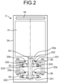
- FIG. 2 is a top view of the manipulator included in the switch according to the first embodiment. Note that FIG. 2 illustrates only two of the drive pulleys 33 installed on the output shaft 32 of the motor 31.
- the manipulator 3 includes the housing 34 that accommodates the motor 31 and the drive pulleys 33.
- a controller 35 that controls rotation of the motor 31 is installed inside the housing 34.
- the manipulator 3 includes mounting plates 36 that each supports the drive pulley 33.
- a shaft portion 33a is formed on each drive pulley 33.
- Each drive pulley 33 is rotatably supported by the shaft portion 33a being supported by the mounting plate 36 via a bearing 33b.
- FIG. 3 is a front view of the drive pulley of the manipulator included in the switch according to the first embodiment, the drive pulley being in a disengaged state.
- FIG. 4 is a front view of the drive pulley of the manipulator included in the switch according to the first embodiment, the drive pulley being in an engaged state.
- the output shaft 32 of the motor 31 is hexagonal in cross section.
- the drive pulley 33 includes a chuck 331.
- the chuck 331 includes: two movers 332 being arranged with the output shaft 32 of the motor 31 interposed therebetween; and solenoids 333 that moves the movers 332.
- a catch 334 which is a groove-like portion to be engaged with the output shaft 32 of the motor 31 is formed in each of the movers 332.
- the solenoids 333 cause the two movers 332 to move along a direction in which the movers 332 are arranged.
- the torque of the output shaft 32 is transmitted to the drive pulley 33 to cause the drive pulley 33 to rotate in accordance with rotation of the output shaft 32.
- an “engaged state” refers to a state of the drive pulley 33 in which the catches 334 of the movers 332 are engaged with the outer peripheral surface of the output shaft 32.
- a “disengaged state” refers to a state of the drive pulley 33 in which the catches 334 of the movers 332 are separated from the outer peripheral surface of the output shaft 32.
- the solenoid 333 is a driver that causes the mover 332 to move between a position where the catch 334 is in the engaged state, in which the catch 334 is engaged with the output shaft 32, and a position where the catch 334 is in the disengaged state, in which the catch 334 is out of contact with the output shaft 32.
- a configuration in which the solenoid 333 is a driver for moving the mover 332 is taken as an example, but the driver is not limited to the solenoid 333.
- the controller 35 controls the solenoids 333 of each drive pulley 33. Note that, illustration of lines connecting the controller 35 and the solenoids 333 has been omitted from FIGS. 2 , 3, and 4 .
- the controller 35 normally brings all the drive pulleys 33 into the disengaged state, and exclusively brings any one of the drive pulleys 33 into the engaged state when causing the disconnector 2 to perform a switching action. Therefore, the output shaft 32 does not simultaneously rotate the plurality of drive pulleys 33. Therefore, the manipulator 3 does not need to be a large device including a high-power motor 31 that simultaneously rotates the plurality of drive pulleys 33. Therefore, the gas-insulated switch 100, which is the switch according to the first embodiment, can suppress an increase in space to install the manipulator 3.
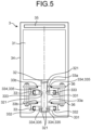
- FIG. 5 is a top view of a manipulator included in a switch according to a second embodiment.
- a pin 335 formed on each mover 332 of the chuck 331 serves as the catch 334.
- holes 321 into which the pins 335 can be inserted are formed in the output shaft 32 of the motor 31.
- the holes 321 are formed at intervals of 180° around the axis of the output shaft 32.
- the holes 321 are formed side by side in an axial direction of the output shaft 32 in accordance with arrangement positions of a plurality of the drive pulleys 33.
- FIG. 6 is a front view of the drive pulley of the manipulator included in the switch according to the second embodiment, the drive pulley being in a disengaged state.
- FIG. 7 is a front view of the drive pulley of the manipulator included in the switch according to the second embodiment, the drive pulley being in an engaged state.
- the output shaft 32 of the motor 31 is circular in cross section.
- the solenoids 333 cause the two movers 332 to move along a direction in which the movers 332 are arranged.
- an “engaged state” refers to a state of the drive pulley 33 in which the pins 335 of the movers 332 are inserted in the holes 321 of the output shaft 32.
- a “disengaged state” refers to a state of the drive pulley 33 in which the pins 335 of the movers 332 have come out of the holes 321 of the output shaft 32.
- the controller 35 controls the solenoids 333 of each drive pulley 33. Note that, illustration of lines connecting the controller 35 and the solenoids 333 has been omitted from FIGS. 5 , 6, and 7 .
- the controller 35 normally brings all the drive pulleys 33 into the disengaged state, and exclusively brings any one of the drive pulleys 33 into the engaged state when causing the disconnector 2 to perform a switching action. Therefore, the output shaft 32 does not simultaneously rotate the plurality of drive pulleys 33. Therefore, the manipulator 3 does not need to be a large device with power output for simultaneously rotating the plurality of drive pulleys 33. Therefore, the gas-insulated switch 100 according to the second embodiment can suppress an increase in space to install the manipulator 3.
- the holes 321 of the output shaft 32 are formed side by side in the axial direction of the output shaft 32 in accordance with the arrangement positions of the drive pulleys 33, when the pins 335 of the movers 332 of any one of the drive pulleys 33 are pulled out from the holes 321, the pins 335 of the movers 332 of all the drive pulleys 33 face the holes 321 of the output shaft 32. Therefore, after the any one of the drive pulleys 33 is brought into the disengaged state, it is possible to bring any desired drive pulley 33 into the engaged state without rotating the output shaft 32.
- the chuck 331 may have a structure including a stator and the mover 332.
- a single solenoid 333 just needs to be provided so as to move the mover 332.
- FIG. 8 is a diagram illustrating a hardware exemplary configuration of each controller of the switches according to the first and second embodiments.
- FIG. 8 illustrates a hardware configuration to be adopted when functions of the controller 35 are implemented by use of hardware that executes programs.
- the controller 35 includes: a processor 91 that executes various types of processing; a memory 92 as a main memory; and a storage 93 that stores information.
- the processor 91 may be an arithmetic means such as an arithmetic unit, a microprocessor, a microcomputer, a central processing unit (CPU), or a digital signal processor (DSP).
- DSP digital signal processor
- the memory 92 a nonvolatile or volatile semiconductor memory such as a random access memory (RAM), a read only memory (ROM), a flash memory, an erasable programmable read only memory (EPROM), or an electrically erasable programmable read only memory (EEPROM (registered trademark)).
- the storage 93 stores programs for controlling the motor 31 and controlling the solenoids 333 of the drive pulleys 33.
- the processor 91 reads the programs stored in the storage 93 into the memory 92, and executes the programs.
- the functions of the controller 35 are implemented by the processor 91 reading the programs stored in the storage 93 into the memory 92 and executing the programs.
Landscapes
- Engineering & Computer Science (AREA)
- Power Engineering (AREA)
- Physics & Mathematics (AREA)
- Electromagnetism (AREA)
- Gas-Insulated Switchgears (AREA)
- Manipulator (AREA)
Abstract
Description
- The present disclosure relates to a switch that opens or closes an electric circuit.
- A disconnector or an opener-closer to be applied to a switch that opens or closes an electric circuit, such as a gas-insulated switch, performs a switching action by torque transmitted from a manipulator including a motor. A pulley is installed in each of the disconnector or the opener-closer and the manipulator, and torque is transmitted from the manipulator to the disconnector or the opener-closer by a wire cable stretched around the pulleys. Thus, a switching action is performed by the disconnector or the opener-closer. The disconnector or the opener-closer and the manipulator are connected on a one-to-one basis. Therefore, it is necessary to provide manipulators equal in number to disconnectors or opener-closers. In a case where, for example, a gas-insulated switch includes a total of five components including grounding switches, as a type of opener-closer, and disconnectors, it is necessary to allow space for installation of five manipulators.
-
Patent Literature 1 discloses a gas-insulated switch that drives a plurality of disconnectors and grounding switches with a single manipulator. The gas-insulated switch disclosed inPatent Literature 1 can reduce space to install the manipulator as compared with a gas-insulated switch in which manipulators of the same number as disconnectors and grounding switches are installed. - Patent Literature 1:
Japanese Patent Application Laid-open No. 2006-296062 - In the gas-insulated switch disclosed in
Patent Literature 1, the number of manipulators is reduced. However, in the gas-insulated switch disclosed inPatent Literature 1, it is necessary to use a manipulator including a high-power motor capable of simultaneously driving respective pulleys of the plurality of disconnectors and grounding switches. - The present disclosure has been made in view of the above, and an object of the present disclosure is to provide a switch that does not require a manipulator including a high-power motor capable of simultaneously driving a plurality of pulleys and that suppresses an increase in space to install a manipulator as compared with a case where a manipulator is installed individually for a disconnector and a switch.
- In order to solve the above-described problem and achieve the object, a switch according to the present disclosure includes: a circuit breaker configured to open or close a power transmission circuit; a disconnector configured to disconnect a part of the power transmission circuit; a grounding switch configured to ground the part of the power transmission circuit disconnected by the circuit breaker; and a manipulator configured to drive the disconnector and the grounding switch. The manipulator includes: a motor; a plurality of drive pulleys installed on an output shaft of the motor; and a controller configured to control rotation of the motor. Each of the disconnector and the grounding switch includes: a driven pulley; and a switching manipulator configured to perform a switching action according to rotation of the driven pulley. A wire, configured to transmit torque of the motor, is stretched around each of the drive pulleys and corresponding one of the driven pulleys. Each of the plurality of drive pulleys includes: a mover including a catch configured to engage with the output shaft; and a chuck including a driver configured to cause the mover to move between a position at which the catch is in an engaged state and a position at which the catch is in a disengaged state. The catch is engaged with the output shaft in the engaged state, and is out of contact with the output shaft in the disengaged state. The controller is configured to exclusively bring one of the plurality of drive pulleys into the engaged state.
- The present disclosure has an effect of providing a switch that does not require a manipulator including a high-power motor capable of simultaneously driving a plurality of pulleys and that suppresses an increase in space to install a manipulator as compared with a case where a manipulator is installed separately for a disconnector and a switch.
-
-
FIG. 1 is a side view of a switch according to a first embodiment. -
FIG. 2 is a top view of a manipulator included in the switch according to the first embodiment. -
FIG. 3 is a front view of a drive pulley of the manipulator included in the switch according to the first embodiment, the drive pulley being in a disengaged state. -
FIG. 4 is a front view of the drive pulley of the manipulator included in the switch according to the first embodiment, the drive pulley being in an engaged state. -
FIG. 5 is a top view of a manipulator included in a switch according to a second embodiment. -
FIG. 6 is a front view of a drive pulley of the manipulator included in the switch according to the second embodiment, the drive pulley being in a disengaged state. -
FIG. 7 is a front view of the drive pulley of the manipulator included in the switch according to the second embodiment, the drive pulley being in an engaged state. -
FIG. 8 is a diagram illustrating a hardware exemplary configuration of each controller of the switches according to the first and second embodiments. - Hereinafter, switches according to embodiments will be described in detail with reference to the drawings.
-
FIG. 1 is a side view of a switch according to a first embodiment. A gas-insulatedswitch 100, which is a switch according to the first embodiment, includes: acircuit breaker 1 that opens or closes a power transmission circuit; a plurality ofdisconnectors 2; and amanipulator 3 that drives thedisconnectors 2. Note that, inFIG. 1 , one surface of ahousing 34 of themanipulator 3 is not illustrated so as to illustrate the inside of thehousing 34. Thedisconnector 2 disconnects a part of the power transmission circuit when the power transmission circuit is in an unloaded state. Thedisconnector 2 is a disconnector including a grounding switch that grounds the disconnected part of the power transmission circuit. Themanipulator 3 includes amotor 31 to cause thedisconnector 2 to perform a switching action. A plurality of drive pulleys 33 are provided on anoutput shaft 32 of themotor 31. In addition, each of the plurality ofdisconnectors 2 includes: a drivenpulley 21 to which torque of thedrive pulley 33 is transmitted; and aswitching manipulator 22 configured to perform a switching action according to rotation of the drivenpulley 21. Awire 4 is stretched around each of the drive pulleys 33 and corresponding one of the driven pulleys 21. Note that, here, the structure in which thedisconnector 2 is a disconnector including a grounding switch is taken as an example, but a grounding switch may be installed separately from thedisconnector 2. -
FIG. 2 is a top view of the manipulator included in the switch according to the first embodiment. Note thatFIG. 2 illustrates only two of the drive pulleys 33 installed on theoutput shaft 32 of themotor 31. Themanipulator 3 includes thehousing 34 that accommodates themotor 31 and the drive pulleys 33. Acontroller 35 that controls rotation of themotor 31 is installed inside thehousing 34. - The
manipulator 3 includes mountingplates 36 that each supports thedrive pulley 33. Ashaft portion 33a is formed on each drivepulley 33. Each drivepulley 33 is rotatably supported by theshaft portion 33a being supported by the mountingplate 36 via abearing 33b. -
FIG. 3 is a front view of the drive pulley of the manipulator included in the switch according to the first embodiment, the drive pulley being in a disengaged state.FIG. 4 is a front view of the drive pulley of the manipulator included in the switch according to the first embodiment, the drive pulley being in an engaged state. Theoutput shaft 32 of themotor 31 is hexagonal in cross section. Thedrive pulley 33 includes achuck 331. Thechuck 331 includes: twomovers 332 being arranged with theoutput shaft 32 of themotor 31 interposed therebetween; andsolenoids 333 that moves themovers 332. - A
catch 334 which is a groove-like portion to be engaged with theoutput shaft 32 of themotor 31 is formed in each of themovers 332. Thesolenoids 333 cause the twomovers 332 to move along a direction in which themovers 332 are arranged. When themovers 332 come into contact with an outer peripheral surface of theoutput shaft 32 and thus, the outer peripheral surface of theoutput shaft 32 is engaged with thecatches 334, the torque of theoutput shaft 32 is transmitted to the drivepulley 33 to cause thedrive pulley 33 to rotate in accordance with rotation of theoutput shaft 32. When themovers 332 are separated from theoutput shaft 32 and thus, the outer peripheral surface of theoutput shaft 32 is disengaged from thecatches 334, the torque of theoutput shaft 32 is not transmitted to thedrive pulley 33. Thus, thedrive pulley 33 does not rotate even if theoutput shaft 32 rotates. Here, an "engaged state" refers to a state of thedrive pulley 33 in which thecatches 334 of themovers 332 are engaged with the outer peripheral surface of theoutput shaft 32. Furthermore, a "disengaged state" refers to a state of thedrive pulley 33 in which thecatches 334 of themovers 332 are separated from the outer peripheral surface of theoutput shaft 32. Therefore, thesolenoid 333 is a driver that causes themover 332 to move between a position where thecatch 334 is in the engaged state, in which thecatch 334 is engaged with theoutput shaft 32, and a position where thecatch 334 is in the disengaged state, in which thecatch 334 is out of contact with theoutput shaft 32. Note that, here, a configuration in which thesolenoid 333 is a driver for moving themover 332 is taken as an example, but the driver is not limited to thesolenoid 333. - The
controller 35 controls thesolenoids 333 of each drivepulley 33. Note that, illustration of lines connecting thecontroller 35 and thesolenoids 333 has been omitted fromFIGS. 2 ,3, and 4 . Thecontroller 35 normally brings all the drive pulleys 33 into the disengaged state, and exclusively brings any one of the drive pulleys 33 into the engaged state when causing thedisconnector 2 to perform a switching action. Therefore, theoutput shaft 32 does not simultaneously rotate the plurality of drive pulleys 33. Therefore, themanipulator 3 does not need to be a large device including a high-power motor 31 that simultaneously rotates the plurality of drive pulleys 33. Therefore, the gas-insulatedswitch 100, which is the switch according to the first embodiment, can suppress an increase in space to install themanipulator 3. - Note that when the
movers 332 of any one of the drive pulleys 33 are released from the engaged state and brought into the disengaged state, bottom surfaces of the grooves of thecatches 334 of themovers 332 of all the drive pulleys 33 face flat-surface portions of the outer peripheral surface of theoutput shaft 32. Therefore, after the any one of the drive pulleys 33 is brought into the disengaged state, it is possible to bring any desireddrive pulley 33 into the engaged state without rotating theoutput shaft 32. -
FIG. 5 is a top view of a manipulator included in a switch according to a second embodiment. In themanipulator 3 of the gas-insulatedswitch 100 serving as the switch according to the second embodiment, a pin 335 formed on eachmover 332 of thechuck 331 serves as thecatch 334. In addition, holes 321 into which the pins 335 can be inserted are formed in theoutput shaft 32 of themotor 31. Theholes 321 are formed at intervals of 180° around the axis of theoutput shaft 32. Furthermore, theholes 321 are formed side by side in an axial direction of theoutput shaft 32 in accordance with arrangement positions of a plurality of the drive pulleys 33. In the axial direction of theoutput shaft 32, positions where theholes 321 are formed correspond to positions where the drive pulleys 33 are installed. Except for this point, the configuration of the gas-insulatedswitch 100 of the second embodiment is similar to the configuration of the gas-insulatedswitch 100 according to the first embodiment. Therefore, description of common points are omitted. -
FIG. 6 is a front view of the drive pulley of the manipulator included in the switch according to the second embodiment, the drive pulley being in a disengaged state.FIG. 7 is a front view of the drive pulley of the manipulator included in the switch according to the second embodiment, the drive pulley being in an engaged state. Theoutput shaft 32 of themotor 31 is circular in cross section. Thesolenoids 333 cause the twomovers 332 to move along a direction in which themovers 332 are arranged. When themovers 332 come into contact with theoutput shaft 32 and thus, the pins 335 serving as thecatches 334 are inserted into theholes 321 of theoutput shaft 32, the torque of theoutput shaft 32 is transmitted to the drivepulley 33 to cause thedrive pulley 33 to rotate according to rotation of theoutput shaft 32. When themovers 332 are separated from theoutput shaft 32 and thus, the pins 335 serving as thecatches 334 come out of theholes 321 of theoutput shaft 32, the torque of theoutput shaft 32 is not transmitted to the drivepulley 33. Thus, thedrive pulley 33 does not rotate even if theoutput shaft 32 rotates. Here, an "engaged state" refers to a state of thedrive pulley 33 in which the pins 335 of themovers 332 are inserted in theholes 321 of theoutput shaft 32. In addition, a "disengaged state" refers to a state of thedrive pulley 33 in which the pins 335 of themovers 332 have come out of theholes 321 of theoutput shaft 32. - The
controller 35 controls thesolenoids 333 of each drivepulley 33. Note that, illustration of lines connecting thecontroller 35 and thesolenoids 333 has been omitted fromFIGS. 5 ,6, and 7 . Thecontroller 35 normally brings all the drive pulleys 33 into the disengaged state, and exclusively brings any one of the drive pulleys 33 into the engaged state when causing thedisconnector 2 to perform a switching action. Therefore, theoutput shaft 32 does not simultaneously rotate the plurality of drive pulleys 33. Therefore, themanipulator 3 does not need to be a large device with power output for simultaneously rotating the plurality of drive pulleys 33. Therefore, the gas-insulatedswitch 100 according to the second embodiment can suppress an increase in space to install themanipulator 3. - Note that since the
holes 321 of theoutput shaft 32 are formed side by side in the axial direction of theoutput shaft 32 in accordance with the arrangement positions of the drive pulleys 33, when the pins 335 of themovers 332 of any one of the drive pulleys 33 are pulled out from theholes 321, the pins 335 of themovers 332 of all the drive pulleys 33 face theholes 321 of theoutput shaft 32. Therefore, after the any one of the drive pulleys 33 is brought into the disengaged state, it is possible to bring any desireddrive pulley 33 into the engaged state without rotating theoutput shaft 32. - Note that although the
chuck 331 includes a pair of themovers 332 in the above description, thechuck 331 may have a structure including a stator and themover 332. In this case, asingle solenoid 333 just needs to be provided so as to move themover 332. When using thechuck 331 including the stator and themover 332, it is possible to cause thecatches 334 to be engaged with theoutput shaft 32 by moving themover 332 with thesolenoid 333 to press theoutput shaft 32 against the stator such that theoutput shaft 32 is sandwiched between themover 332 and the stator. - Next, a description will be given of a hardware configuration of the
controller 35 of themanipulator 3 included in the gas-insulatedswitch 100 that is the switch according to each of the first and second embodiments described above.FIG. 8 is a diagram illustrating a hardware exemplary configuration of each controller of the switches according to the first and second embodiments.FIG. 8 illustrates a hardware configuration to be adopted when functions of thecontroller 35 are implemented by use of hardware that executes programs. - The
controller 35 includes: a processor 91 that executes various types of processing; amemory 92 as a main memory; and astorage 93 that stores information. The processor 91 may be an arithmetic means such as an arithmetic unit, a microprocessor, a microcomputer, a central processing unit (CPU), or a digital signal processor (DSP). Furthermore, it is possible to use, as thememory 92, a nonvolatile or volatile semiconductor memory such as a random access memory (RAM), a read only memory (ROM), a flash memory, an erasable programmable read only memory (EPROM), or an electrically erasable programmable read only memory (EEPROM (registered trademark)). Thestorage 93 stores programs for controlling themotor 31 and controlling thesolenoids 333 of the drive pulleys 33. The processor 91 reads the programs stored in thestorage 93 into thememory 92, and executes the programs. The functions of thecontroller 35 are implemented by the processor 91 reading the programs stored in thestorage 93 into thememory 92 and executing the programs. - The configurations set forth in the above embodiments show examples of the subject matter, and it is possible to combine the configurations with another known technique, and is also possible to partially omit or change the configurations without departing from the scope of the present disclosure.
- 1 circuit breaker; 2 disconnector; 3 manipulator; 4 wire; 21 driven pulley; 22 switching manipulator; 31 motor; 32 output shaft; 33 drive pulley; 33a shaft portion; 33b bearing; 34 housing; 35 controller; 36 mounting plate; 91 processor; 92 memory; 93 storage; 100 gas-insulated switch; 321 hole; 331 chuck; 332 mover; 333 solenoid; 334 catch; 335 pin.
Claims (5)
- A switch comprising:a circuit breaker configured to open or close a power transmission circuit;a disconnector configured to disconnect a part of the power transmission circuit;a grounding switch configured to ground the part of the power transmission circuit disconnected by the circuit breaker; anda manipulator configured to drive the disconnector and the grounding switch, whereinthe manipulator includes:a motor;a plurality of drive pulleys installed on an output shaft of the motor; anda controller configured to control rotation of the motor, whereineach of the disconnector and the grounding switch includes:a driven pulley; anda switching manipulator configured to perform a switching action according to rotation of the driven pulley, whereina wire, configured to transmit torque of the motor, is stretched around each of the drive pulleys and corresponding one of the driven pulleys, whereineach of the plurality of drive pulleys includes:a mover including a catch configured to engage with the output shaft; anda chuck including a driver configured to cause the mover to move between a position at which the catch is in an engaged state and a position at which the catch is in a disengaged state, whereinthe catch is engaged with the output shaft in the engaged state, and is out of contact with the output shaft in the disengaged state, andthe controller is configured to exclusively bring one of the plurality of drive pulleys into the engaged state.
- The switch according to claim 1, whereinthe output shaft is a shaft with a polygonal cross section, andthe catch includes a groove configured to engage with a corner of an outer peripheral surface of the output shaft.
- The switch according to claim 1, whereina plurality of holes are formed in an outer peripheral surface of the output shaft, the plurality of holes corresponding to installation positions of the plurality of drive pulleys, andthe catch of each of the plurality of drive pulleys has a protrusion that can be inserted into the hole.
- The switch according to claim 3, wherein the plurality of holes are formed side by side in an axial direction of the output shaft.
- The switch according to claim 1, wherein
the chuck is configured to hold the output shaft by means of the movers from two directions opposite to each other, the two directions being perpendicular to the output shaft.
Applications Claiming Priority (1)
| Application Number | Priority Date | Filing Date | Title |
|---|---|---|---|
| PCT/JP2022/017046 WO2023195045A1 (en) | 2022-04-04 | 2022-04-04 | Opening/closing device |
Publications (3)
| Publication Number | Publication Date |
|---|---|
| EP4506975A1 true EP4506975A1 (en) | 2025-02-12 |
| EP4506975A4 EP4506975A4 (en) | 2025-05-07 |
| EP4506975B1 EP4506975B1 (en) | 2026-02-25 |
Family
ID=83637957
Family Applications (1)
| Application Number | Title | Priority Date | Filing Date |
|---|---|---|---|
| EP22936448.4A Active EP4506975B1 (en) | 2022-04-04 | 2022-04-04 | Opening/closing device |
Country Status (4)
| Country | Link |
|---|---|
| US (1) | US20250079093A1 (en) |
| EP (1) | EP4506975B1 (en) |
| JP (1) | JP7154467B1 (en) |
| WO (1) | WO2023195045A1 (en) |
Family Cites Families (7)
| Publication number | Priority date | Publication date | Assignee | Title |
|---|---|---|---|---|
| JP2000285772A (en) * | 1999-03-30 | 2000-10-13 | Nissin Electric Co Ltd | Switchgear |
| JP2006296062A (en) | 2005-04-08 | 2006-10-26 | Hitachi Ltd | Gas insulated switchgear |
| FR2923661B1 (en) * | 2007-11-13 | 2010-04-30 | Areva T & D Sa | SWITCHING APPARATUS WITH CIRCUIT BREAKER AND DISCONNECT AND COMPRISING COMMON TRAINING MEANS |
| KR100988133B1 (en) * | 2008-04-25 | 2010-10-18 | 엘에스산전 주식회사 | Switchgear drive device of high voltage breaker |
| JP5367594B2 (en) * | 2010-01-13 | 2013-12-11 | 株式会社東芝 | Switch operating device |
| WO2015111133A1 (en) * | 2014-01-21 | 2015-07-30 | 三菱電機株式会社 | Gas-insulated switchgear and switch |
| JP2016173960A (en) * | 2015-03-18 | 2016-09-29 | 株式会社日立製作所 | Disconnector with earthing switch and switchgear |
-
2022
- 2022-04-04 JP JP2022544210A patent/JP7154467B1/en active Active
- 2022-04-04 EP EP22936448.4A patent/EP4506975B1/en active Active
- 2022-04-04 WO PCT/JP2022/017046 patent/WO2023195045A1/en not_active Ceased
- 2022-04-04 US US18/727,513 patent/US20250079093A1/en active Pending
Also Published As
| Publication number | Publication date |
|---|---|
| JP7154467B1 (en) | 2022-10-17 |
| US20250079093A1 (en) | 2025-03-06 |
| WO2023195045A1 (en) | 2023-10-12 |
| EP4506975B1 (en) | 2026-02-25 |
| EP4506975A4 (en) | 2025-05-07 |
| JPWO2023195045A1 (en) | 2023-10-12 |
Similar Documents
| Publication | Publication Date | Title |
|---|---|---|
| US4527028A (en) | Modular vacuum interrupter | |
| EP1214765B1 (en) | Gas-insulated switchgear device | |
| EP1709653B1 (en) | Modular switching device | |
| EP3435540A1 (en) | Apparatus and method for modifying an electrical configuration of an electric drive | |
| EP4506975B1 (en) | Opening/closing device | |
| US8803012B2 (en) | High-voltage assembly | |
| EP3089186A1 (en) | Electrical switchgear and method of operating an electrical switchgear | |
| JP5661223B1 (en) | Gas insulated switchgear and switchgear | |
| KR0131138B1 (en) | Modular terminal box for application to electric motor of motorized valves | |
| JP2016173960A (en) | Disconnector with earthing switch and switchgear | |
| KR102334137B1 (en) | Device for preventing corrosion of distribution cable connecter terminal | |
| EP1137105B1 (en) | Feedthrough terminal block | |
| CN110021494A (en) | Transmission system and switchgear for grounding switch in switch cabinet | |
| US20060220470A1 (en) | Device for actuating an electrical switchgear | |
| CN212785091U (en) | An electric commutation device for mining DC motor | |
| KR102485880B1 (en) | DS/ES Operating Mechanism of Gas Insulated Switchgear | |
| KR100311532B1 (en) | Earthing switch device of switchboard | |
| KR100492753B1 (en) | Permanent magnetic actuator of vaccum circuit breaker | |
| US9799468B2 (en) | Support assembly for a micro-switch of a switching device | |
| JP2006296062A (en) | Gas insulated switchgear | |
| CN222507435U (en) | Isolating switch driven by molded case circuit breaker operating mechanism | |
| US10347437B2 (en) | Disconnector device and arrangement for disconnecting a contactor | |
| KR102318984B1 (en) | Disconnector for gas insulated switchgear | |
| US20240021384A1 (en) | Power connection for safe energizing of a power unit in a motor control center | |
| US20240339889A1 (en) | Mechanical inter-lock fail-safe for high voltage connection |
Legal Events
| Date | Code | Title | Description |
|---|---|---|---|
| STAA | Information on the status of an ep patent application or granted ep patent |
Free format text: STATUS: THE INTERNATIONAL PUBLICATION HAS BEEN MADE |
|
| PUAI | Public reference made under article 153(3) epc to a published international application that has entered the european phase |
Free format text: ORIGINAL CODE: 0009012 |
|
| STAA | Information on the status of an ep patent application or granted ep patent |
Free format text: STATUS: REQUEST FOR EXAMINATION WAS MADE |
|
| 17P | Request for examination filed |
Effective date: 20240702 |
|
| AK | Designated contracting states |
Kind code of ref document: A1 Designated state(s): AL AT BE BG CH CY CZ DE DK EE ES FI FR GB GR HR HU IE IS IT LI LT LU LV MC MK MT NL NO PL PT RO RS SE SI SK SM TR |
|
| REG | Reference to a national code |
Ref country code: DE Ref legal event code: R079 Free format text: PREVIOUS MAIN CLASS: H01H0033360000 Ipc: H01H0033420000 Ref country code: DE Ref legal event code: R079 Ref document number: 602022031404 Country of ref document: DE Free format text: PREVIOUS MAIN CLASS: H01H0033360000 Ipc: H01H0033420000 |
|
| A4 | Supplementary search report drawn up and despatched |
Effective date: 20250402 |
|
| RIC1 | Information provided on ipc code assigned before grant |
Ipc: H02B 13/075 20060101ALN20250328BHEP Ipc: H02B 13/035 20060101ALI20250328BHEP Ipc: H01H 33/36 20060101ALI20250328BHEP Ipc: H01H 9/26 20060101ALI20250328BHEP Ipc: H01H 3/36 20060101ALI20250328BHEP Ipc: H01H 33/42 20060101AFI20250328BHEP |
|
| DAV | Request for validation of the european patent (deleted) | ||
| DAX | Request for extension of the european patent (deleted) | ||
| GRAP | Despatch of communication of intention to grant a patent |
Free format text: ORIGINAL CODE: EPIDOSNIGR1 |
|
| STAA | Information on the status of an ep patent application or granted ep patent |
Free format text: STATUS: GRANT OF PATENT IS INTENDED |
|
| RIC1 | Information provided on ipc code assigned before grant |
Ipc: H01H 33/42 20060101AFI20250917BHEP Ipc: H01H 3/36 20060101ALI20250917BHEP Ipc: H01H 9/26 20060101ALI20250917BHEP Ipc: H01H 33/36 20060101ALI20250917BHEP Ipc: H02B 13/035 20060101ALI20250917BHEP Ipc: H02B 13/075 20060101ALN20250917BHEP |
|
| INTG | Intention to grant announced |
Effective date: 20250929 |
|
| GRAS | Grant fee paid |
Free format text: ORIGINAL CODE: EPIDOSNIGR3 |
|
| GRAA | (expected) grant |
Free format text: ORIGINAL CODE: 0009210 |
|
| STAA | Information on the status of an ep patent application or granted ep patent |
Free format text: STATUS: THE PATENT HAS BEEN GRANTED |
|
| AK | Designated contracting states |
Kind code of ref document: B1 Designated state(s): AL AT BE BG CH CY CZ DE DK EE ES FI FR GB GR HR HU IE IS IT LI LT LU LV MC MK MT NL NO PL PT RO RS SE SI SK SM TR |
|
| REG | Reference to a national code |
Ref country code: CH Ref legal event code: F10 Free format text: ST27 STATUS EVENT CODE: U-0-0-F10-F00 (AS PROVIDED BY THE NATIONAL OFFICE) Effective date: 20260225 Ref country code: GB Ref legal event code: FG4D |
|
| REG | Reference to a national code |
Ref country code: CH Ref legal event code: R17 Free format text: ST27 STATUS EVENT CODE: U-0-0-R10-R17 (AS PROVIDED BY THE NATIONAL OFFICE) Effective date: 20260227 |
|
| REG | Reference to a national code |
Ref country code: DE Ref legal event code: R096 Ref document number: 602022031404 Country of ref document: DE |
|
| REG | Reference to a national code |
Ref country code: IE Ref legal event code: FG4D |
|
| PGFP | Annual fee paid to national office [announced via postgrant information from national office to epo] |
Ref country code: FR Payment date: 20260323 Year of fee payment: 5 |
|
| REG | Reference to a national code |
Ref country code: CH Ref legal event code: U11 Free format text: ST27 STATUS EVENT CODE: U-0-0-U10-U11 (AS PROVIDED BY THE NATIONAL OFFICE) Effective date: 20260501 |