EP4506665A1 - Device for reading and monitoring gas supply and operation method thereof - Google Patents
Device for reading and monitoring gas supply and operation method thereof Download PDFInfo
- Publication number
- EP4506665A1 EP4506665A1 EP23425051.2A EP23425051A EP4506665A1 EP 4506665 A1 EP4506665 A1 EP 4506665A1 EP 23425051 A EP23425051 A EP 23425051A EP 4506665 A1 EP4506665 A1 EP 4506665A1
- Authority
- EP
- European Patent Office
- Prior art keywords
- values
- module
- predetermined threshold
- threshold values
- sensors
- Prior art date
- Legal status (The legal status is an assumption and is not a legal conclusion. Google has not performed a legal analysis and makes no representation as to the accuracy of the status listed.)
- Pending
Links
Images



Classifications
-
- G—PHYSICS
- G01—MEASURING; TESTING
- G01F—MEASURING VOLUME, VOLUME FLOW, MASS FLOW OR LIQUID LEVEL; METERING BY VOLUME
- G01F1/00—Measuring the volume flow or mass flow of fluid or fluent solid material wherein the fluid passes through a meter in a continuous flow
- G01F1/66—Measuring the volume flow or mass flow of fluid or fluent solid material wherein the fluid passes through a meter in a continuous flow by measuring frequency, phase shift or propagation time of electromagnetic or other waves, e.g. using ultrasonic flowmeters
-
- G—PHYSICS
- G05—CONTROLLING; REGULATING
- G05B—CONTROL OR REGULATING SYSTEMS IN GENERAL; FUNCTIONAL ELEMENTS OF SUCH SYSTEMS; MONITORING OR TESTING ARRANGEMENTS FOR SUCH SYSTEMS OR ELEMENTS
- G05B23/00—Testing or monitoring of control systems or parts thereof
- G05B23/02—Electric testing or monitoring
- G05B23/0205—Electric testing or monitoring by means of a monitoring system capable of detecting and responding to faults
- G05B23/0218—Electric testing or monitoring by means of a monitoring system capable of detecting and responding to faults characterised by the fault detection method dealing with either existing or incipient faults
- G05B23/0221—Preprocessing measurements, e.g. data collection rate adjustment; Standardization of measurements; Time series or signal analysis, e.g. frequency analysis or wavelets; Trustworthiness of measurements; Indexes therefor; Measurements using easily measured parameters to estimate parameters difficult to measure; Virtual sensor creation; De-noising; Sensor fusion; Unconventional preprocessing inherently present in specific fault detection methods like PCA-based methods
-
- G—PHYSICS
- G01—MEASURING; TESTING
- G01F—MEASURING VOLUME, VOLUME FLOW, MASS FLOW OR LIQUID LEVEL; METERING BY VOLUME
- G01F15/00—Details of, or accessories for, apparatus of groups G01F1/00 - G01F13/00 insofar as such details or appliances are not adapted to particular types of such apparatus
- G01F15/001—Means for regulating or setting the meter for a predetermined quantity
- G01F15/002—Means for regulating or setting the meter for a predetermined quantity for gases
-
- G—PHYSICS
- G01—MEASURING; TESTING
- G01F—MEASURING VOLUME, VOLUME FLOW, MASS FLOW OR LIQUID LEVEL; METERING BY VOLUME
- G01F15/00—Details of, or accessories for, apparatus of groups G01F1/00 - G01F13/00 insofar as such details or appliances are not adapted to particular types of such apparatus
- G01F15/007—Details of, or accessories for, apparatus of groups G01F1/00 - G01F13/00 insofar as such details or appliances are not adapted to particular types of such apparatus comprising means to prevent fraud
-
- G—PHYSICS
- G01—MEASURING; TESTING
- G01F—MEASURING VOLUME, VOLUME FLOW, MASS FLOW OR LIQUID LEVEL; METERING BY VOLUME
- G01F15/00—Details of, or accessories for, apparatus of groups G01F1/00 - G01F13/00 insofar as such details or appliances are not adapted to particular types of such apparatus
- G01F15/02—Compensating or correcting for variations in pressure, density or temperature
-
- G—PHYSICS
- G01—MEASURING; TESTING
- G01F—MEASURING VOLUME, VOLUME FLOW, MASS FLOW OR LIQUID LEVEL; METERING BY VOLUME
- G01F15/00—Details of, or accessories for, apparatus of groups G01F1/00 - G01F13/00 insofar as such details or appliances are not adapted to particular types of such apparatus
- G01F15/02—Compensating or correcting for variations in pressure, density or temperature
- G01F15/022—Compensating or correcting for variations in pressure, density or temperature using electrical means
- G01F15/024—Compensating or correcting for variations in pressure, density or temperature using electrical means involving digital counting
-
- G—PHYSICS
- G01—MEASURING; TESTING
- G01F—MEASURING VOLUME, VOLUME FLOW, MASS FLOW OR LIQUID LEVEL; METERING BY VOLUME
- G01F15/00—Details of, or accessories for, apparatus of groups G01F1/00 - G01F13/00 insofar as such details or appliances are not adapted to particular types of such apparatus
- G01F15/06—Indicating or recording devices
- G01F15/061—Indicating or recording devices for remote indication
- G01F15/063—Indicating or recording devices for remote indication using electrical means
-
- G—PHYSICS
- G01—MEASURING; TESTING
- G01K—MEASURING TEMPERATURE; MEASURING QUANTITY OF HEAT; THERMALLY-SENSITIVE ELEMENTS NOT OTHERWISE PROVIDED FOR
- G01K13/00—Thermometers specially adapted for specific purposes
- G01K13/02—Thermometers specially adapted for specific purposes for measuring temperature of moving fluids or granular materials capable of flow
-
- G—PHYSICS
- G01—MEASURING; TESTING
- G01K—MEASURING TEMPERATURE; MEASURING QUANTITY OF HEAT; THERMALLY-SENSITIVE ELEMENTS NOT OTHERWISE PROVIDED FOR
- G01K13/00—Thermometers specially adapted for specific purposes
- G01K13/02—Thermometers specially adapted for specific purposes for measuring temperature of moving fluids or granular materials capable of flow
- G01K13/024—Thermometers specially adapted for specific purposes for measuring temperature of moving fluids or granular materials capable of flow of moving gases
-
- G—PHYSICS
- G01—MEASURING; TESTING
- G01L—MEASURING FORCE, STRESS, TORQUE, WORK, MECHANICAL POWER, MECHANICAL EFFICIENCY, OR FLUID PRESSURE
- G01L19/00—Details of, or accessories for, apparatus for measuring steady or quasi-steady pressure of a fluent medium insofar as such details or accessories are not special to particular types of pressure gauges
- G01L19/0007—Fluidic connecting means
- G01L19/0023—Fluidic connecting means for flowthrough systems having a flexible pressure transmitting element
-
- G—PHYSICS
- G01—MEASURING; TESTING
- G01L—MEASURING FORCE, STRESS, TORQUE, WORK, MECHANICAL POWER, MECHANICAL EFFICIENCY, OR FLUID PRESSURE
- G01L19/00—Details of, or accessories for, apparatus for measuring steady or quasi-steady pressure of a fluent medium insofar as such details or accessories are not special to particular types of pressure gauges
- G01L19/0007—Fluidic connecting means
- G01L19/003—Fluidic connecting means using a detachable interface or adapter between the process medium and the pressure gauge
-
- G—PHYSICS
- G01—MEASURING; TESTING
- G01M—TESTING STATIC OR DYNAMIC BALANCE OF MACHINES OR STRUCTURES; TESTING OF STRUCTURES OR APPARATUS, NOT OTHERWISE PROVIDED FOR
- G01M3/00—Investigating fluid-tightness of structures
- G01M3/02—Investigating fluid-tightness of structures by using fluid or vacuum
- G01M3/26—Investigating fluid-tightness of structures by using fluid or vacuum by measuring rate of loss or gain of fluid, e.g. by pressure-responsive devices, by flow detectors
- G01M3/28—Investigating fluid-tightness of structures by using fluid or vacuum by measuring rate of loss or gain of fluid, e.g. by pressure-responsive devices, by flow detectors for pipes, cables or tubes; for pipe joints or seals; for valves ; for welds
- G01M3/2807—Investigating fluid-tightness of structures by using fluid or vacuum by measuring rate of loss or gain of fluid, e.g. by pressure-responsive devices, by flow detectors for pipes, cables or tubes; for pipe joints or seals; for valves ; for welds for pipes
- G01M3/2815—Investigating fluid-tightness of structures by using fluid or vacuum by measuring rate of loss or gain of fluid, e.g. by pressure-responsive devices, by flow detectors for pipes, cables or tubes; for pipe joints or seals; for valves ; for welds for pipes using pressure measurements
-
- G—PHYSICS
- G05—CONTROLLING; REGULATING
- G05B—CONTROL OR REGULATING SYSTEMS IN GENERAL; FUNCTIONAL ELEMENTS OF SUCH SYSTEMS; MONITORING OR TESTING ARRANGEMENTS FOR SUCH SYSTEMS OR ELEMENTS
- G05B23/00—Testing or monitoring of control systems or parts thereof
- G05B23/02—Electric testing or monitoring
- G05B23/0205—Electric testing or monitoring by means of a monitoring system capable of detecting and responding to faults
- G05B23/0259—Electric testing or monitoring by means of a monitoring system capable of detecting and responding to faults characterized by the response to fault detection
- G05B23/0267—Fault communication, e.g. human machine interface [HMI]
- G05B23/027—Alarm generation, e.g. communication protocol; Forms of alarm
Definitions
- the present invention concerns the reading and control of gas supply, equipped with an interruption and reset system, in particular to guarantee safety during its operation.
- the invention concerns a device of the aforementioned type, designed and created in particular for the reading and the control of gas consumption for residential users, but which can be used for any type of system, for which reading and control of the gas supply are necessary, especially to secure the downstream system in the event of anomalous situations.
- gas meters are devices capable of informing the network manager and a user of the gas consumed by the user, indicating the total volume of gas that has flowed through the section of the pipe on which a meter is installed.
- devices that are positioned around a passage of a fluid, for example, a duct for the passage of gas, equipped with at least one motion sensor in contact with the casing of the device, and a sensor to detect variations in the inclination of the device wrapped around the duct are becoming more widespread.
- the data collected by the sensors are used by a control unit that detects attempts to break into the casing.
- This type of apparatus is generally used at the end part of a fluid passage, for example, near a gas meter.
- a fluid measuring device connected to an interruption unit capable of detecting a fluid leak by means of a sensor that detects the speed of the fluid flow and transmits a command to a control panel to close a means for interruption of the flow, which interrupts the passage of the fluid in case of a leak.
- Another scope is to provide a device equipped with sensors, an input connector and an output connector, through which gas flows, a gas supply blocking device and a control logic unit capable of carrying out a consumption reading and managing the gas supply safely.
- Another scope of the invention is to provide a device equipped with means for activating or inhibiting a gas supply blocking member.
- Another scope of the invention is to provide a device for gas distribution capable of dynamically adapting the threshold values according to the user's consumption habits and/or environmental conditions and/or variations in the distribution network.
- Another scope of the invention is to provide a device for dispensing and controlling gas, equipped with one or more sensors to verify the presence of tampering with the device.
- a further scope of the present invention is to provide the tools necessary for carrying out the method, and the apparatus which carry out this method.
- Another scope of the invention is to provide a device equipped with measurement sensors for different physical quantities and a device control unit capable of stopping the gas supply, based on values measured by said sensors.
- Another scope is to provide a communication unit for transmitting data, for example, relating to alarms or diagnostics and/or for receiving commands from a central management system.
- a common gas meter does not provide the possibility of storing time series of measurements relating to the operation of the gas network near the meter.
- Said further device can be a data-logger 200', which allows storing values, for example, of the pressure measured at regular intervals and for a predefined period of time, and communicating remotely with the distribution network manager.
- the device of the present invention is essentially a device 1, for reading and controlling the gas supply, in which an input connector 11 and an output connector 12 are obtained of a pipe in which gas flows from a distribution network towards at least one residential user, comprising a control logic unit 2 for the operation of said device 1, and for storing predetermined threshold values, comprising a plurality of sensors 3, operatively connected to said control logic unit 2, for measurement of values of physical quantities and sending them to said control logic unit 2, a gas supply blocking member 4, operatively connected to said control logic unit 2, said control logic unit 2 being configured to compare said values measured and received by said plurality of sensors 3 with said predetermined threshold values, to send alarm signals and to activate said blocking member 4 to block the gas supply, if said measured values are higher than said values of the predetermined thresholds.
- the device 1 essentially comprises a first housing 10 and a second housing 13 communicating with each other.
- Said first housing 10 has on its external surface an input connector 11 and an output connector 12 of a pipe in which gas flows from a distribution network towards residential users, and internally includes the gas pipe, a blocking member 4 for closing the gas supply, and one or more sensors of said plurality of sensors 3.
- Said first housing 10 is preferably made of pressed steel, or polymeric material, in order to guarantee high resistance to corrosion, both external and internal, resistance to high operating temperatures, and high hydraulic tightness, for example, to withstand a pressure of at least 0.5 bar.
- the second housing 13 includes the control logic unit 2 and a power supply.
- the second housing 13 also contains a plurality of sensors 3 and a transceiver unit 5, operationally connected to the control logic unit.
- the second housing 13 includes, on one of its external surfaces, an optical display 6, for example, a display to display the data or values measured by the sensors 3, and a reset button 7.
- an optical display 6 for example, a display to display the data or values measured by the sensors 3, and a reset button 7.
- the device 1 can include a door to access the internal part of said second housing 13, so as to be able to replace the sensors of said plurality of sensors 3 or said control logic unit 2, if a failure or excessive use occurs of the same.
- control logic unit 2 comprises an access module 21, a first comparison module 22, a recording module 23, a processing module 24, a second comparison module 25, an interruption module 26, and a reopening module 27.
- control logic unit 2 is a PLC - programmable logic controller type processor, i.e. a computer for industrial use adapted to the control and execution of processes of components controlled by it.
- the threshold value access module 21 is configured to receive or read, from an archive, predetermined first and/or second threshold values.
- Said access module 21 interacts with an archive where the values measured and sent by said plurality of sensors 3 and the first threshold values are stored, for example, pre-established values of normal operation of said device 1, such as pressure, flow, and temperature.
- the first comparison module 22 is configured to receive the values measured by said plurality of sensors 3 and compare them with the first predetermined threshold values, received from the access module 21, which the comparison module 22 accesses.
- the recording module 23 is operationally connected to the plurality of sensors 3, to record one or more time series of said values measured by each sensor of said plurality 3.
- the recording duration i.e. the time during which to record a series and/or the recording frequency, i.e. the time interval between two different detections of the same sensor, are configurable using the recording module 23.
- a component for example, a joint, a valve or similar, in order to verify the correct installation of the component.
- the recording module 23 can be configured to log sensor data, for example, every three hours during a week to monitor gas supply following an outage. In this way, the recording of time series is managed in such a way as to record a greater number of data where necessary and to reduce the number of recorded data so as not to saturate the data archive to which the access module 21 has accessed.
- An example of data acquisition from a plurality of sensors, as shown in figure 7 will be described below.
- the processing module 24 is configured to process said one or more time series recorded by said recording module 23.
- processing one or more time series is to be understood as performing mathematical operations with said time series.
- these mathematical operations include calculating the average of the values measured by a sensor during a given time interval or excluding an outlier, i.e., a value outside the range of acceptable values for a given sensor.
- Said processing module can be configured to process a plurality of time series each corresponding to a sensor of said plurality of sensors 3 in such a way as to combine said time series and define a parameter to be compared with a second threshold value.
- the calculation of the parameters to be compared is not limited to a single sensor, or to multiple sensors of the same type, but can define a parameter based on the processing of various physical quantities, which cooperate or coexist to decide whether it is necessary to stop the gas supply or if it is safe to proceed with the supply itself.
- the second comparison module 25 is configured to compare said one or more time series recorded by the recording module 23, and possibly processed by the processing module 24, with said second predetermined threshold values.
- the interruption module 26 is a module of the control logic unit 2 capable of communicating with the blocking device 2.
- the interruption module 26 is configured to send an alarm signal and activate said blocking device 4 to block the gas supply, if said values measured by the sensors 3 are higher than said first predetermined threshold values.
- control logic unit 2 sends, for example through the interruption module 26, the alarm signal to a display 6 to facilitate alarm information to the user.
- the interruption module 26 activates the blocking member 4, for example, via the transceiver unit 5, as described below.
- the blocking member 4 is a solenoid valve capable of blocking or allowing the flow of gas towards the residential network.
- the reopening module 27 is configured to send an inhibition command of said blocking member 4 to inhibit said blocking member 4 and allow the supply of gas, if said measured values are higher than said first predetermined threshold values and if the values obtained from a processing of said one or more series, by means of said processing module, are lower than said second predetermined threshold values.
- the presence of the reopening module 27 is advantageous as it allows the gas pipe to deliver gas to the users in the presence of an alert signal corresponding to a value outside the permitted range which does not last over time. In fact, if a temperature value is above a maximum temperature at a certain moment, it is possible to verify that this temperature has returned to an admissible value before blocking the gas supply.
- first threshold value for the maximum range of 6 m 3 /h and define a second threshold value for the maximum range equal to 7.2 m 3 /h, where said second threshold value corresponds to the rate at which the network is overloaded.
- This second threshold value is relevant when evaluating the gas supply over time.
- using the reopening module 27 it is possible to maintain the gas supply even when measuring a range greater than 6 m 3 /h for a certain time interval, provided that said measured flow rate does not exceed the second value of 7.2 m 3 /h in that time interval.
- processing module 24 allows one or more time series to be processed and since the comparison module 25 can compare one or more time series with one or more of said first threshold values, it is possible to combine one or more values and one or multiple time series obtained from sensors of different nature to decide whether to block the supply.
- Combining one or more values and one or more time series obtained from sensors of different natures to decide whether to block the supply includes, for example, that the interruption module 26 sends a blocking signal to the blocking member 4 if the measured flow rate from a sensor inside the pipe is greater than 6 m 3 /h and the pressure measured in the pipe is greater than 32 mbar.
- the first and second threshold values can also include minimum threshold values to be respected.
- An example of the first minimum threshold value for pressure is a value equal to 13 mbar.
- the device 1 includes the following types of sensors: a pressure sensor 31, a flow sensor 32, a seismic sensor 33, and a temperature sensor 34.
- One or more pressure sensors 31 are arranged inside the first housing 10, and measure the gas supply pressure both in the gas inlet section 11 and in the gas outlet section 12.
- the flow sensor 32 is arranged inside the first housing 10 and is able to continuously control the flow of gas flowing in the tube.
- the flow sensor 32 is able to measure mixtures of methane gas with other gases of different nature, such as, for example, synthetic methane, biomethane, and hydrogen.
- a flow sensor 32 with said characteristics makes the device 1 versatile and compatible with a plurality of gas mixtures.
- the flow sensor 32 is preferably an ultrasonic sensor arranged in contact with the gas in the outlet portion of the gas tube.
- Some examples of the device 1 provide an integrated sensor that includes the flow sensor 32 and the temperature sensor 34.
- an integrated ultrasonic sensor sends waves into the gas pipe and detects the flow rate, the time the gas passes through the sensor, the temperature and samples these values with a defined period, i.e., at regular intervals. Examples of the sampling period are every 125 ms or every 250 ms.
- control logic unit 2 is able to define a sampling period different from those described above.
- the temperature sensor 34 is able to send the measured values to said control logic unit 2 which carries out a comparison with a predefined threshold temperature value, stored in said archive and accessible via the access module 21 of said control logic unit 2.
- said temperature sensor 34 in contact with the gas, is used to correctly account for the quantity of gas flowing through the device 1 and can be used to detect potential fires, for example when the temperature is above 80 °C .
- the plurality of sensors 3 can include a further environmental pressure sensor, a smoke or flame sensor, a hygrometer, and the like, which can be integrated together or each connected to the control logic unit 2.
- the plurality of sensors 3 comprises one or more sensors capable of detecting a tampering attempt.
- an accelerometer or a seismic sensor it is possible to verify whether the device 1, or a part of it, for example, the meter, has been removed without authorization. In fact, a non-zero value of said sensors can indicate that device 1 has been removed.
- tampering can be confirmed by reading a pressure sensor.
- the plurality of sensors 3 can include a pressure sensor arranged outside the device 1 to monitor that the device 1 remains in the installation position and recognize when the device 1 is disconnected from the network and, therefore, to identify an attempt of tampering, which corresponds to a zero relative pressure value.
- the transceiver unit 5 described above is operationally connected with said control logic unit 2, to which it is connected physically, or via wireless connection, for example, ZigBee, Wi-fi, Bluetooth, or the like.
- the transceiver unit 5 includes at least a remote communication modem, an antenna, and a local communication port, or the like.
- the transceiver unit 5 communicates in real time to the outside of the device 1, or sends data packets of predefined sizes.
- Sending packets can be encoded to save the time of sending and a unique device identification code.
- this code include a digital signature that corresponds to each device or the device's serial number.
- the power supply is preferably a battery and may include a charge status indicator.
- the plurality of sensors 3 measures the values and sends them to the first comparison module 22 and to the recording module 23.
- the first comparison module uses the values received from the plurality of sensors to compare each of said values with a respective first threshold that the comparison module receives from the access module 21, which accesses an archive, for example, a database or a table of predefined values for each of the quantities measured by the sensors.
- the interruption module 26 also sends an alarm signal to be displayed on the display 6, which will differ based on the type of anomaly.
- the recording module 23 operationally connected to the plurality of sensors 3, records one or more time series of said values measured by each sensor and communicates with the processing module, to which it sends said one or more time series.
- the processing module 24 Starting from the received time series, the processing module 24 performs series processing, i.e. one or more mathematical operations on said series. These mathematical operations, as described above, include the arithmetic mean, the median, the maximum, the minimum, the creation of indirect parameters that combine the values of two or more physical quantities measured by the plurality of sensors 3.
- the comparison between the processed time series and the second threshold values allows the blocking device not to be closed even though a sensor can measure a value greater than the first predetermined threshold, as long as a second condition is respected, i.e., that the corresponding time series does not is greater than the second predetermined threshold.
- control logic unit 2 is able to detect potential gas leaks inside the pipe of a residential user, both during the installation phase and during normal use, and thanks to the reopening module 27. the control logic unit 2 will be able to ignore the supply stop signals if the dispersions are negligible or last such a limited time that they are not dangerous or increase consumption.
- the device 1 allows managing the gas supply based on one or more sensors of said plurality of sensors 3.
- the operation of the device 1 is described below as a function of the values measured by a pressure sensor 31.
- the operator or user after having verified that all domestic gas appliances are closed, can then press a reset button, which is preferably arranged on the external surface of said second housing 13.
- control logic unit 2 checks for any gas leaks on the residential user.
- control logic unit 2 commands the closing of said blocking member 4.
- control logic unit 2 sends an alarm message to the display 6 which projects it.
- control logic unit 2 commands the reopening of said blocking device 4.
- the pressure sensor 31 If the pressure sensor 31 is arranged in proximity to the distribution network, it can detect a pressure drop on the gas distribution network, for example, due to a malfunction on the network.
- the logic control units 2 of the various devices 1 connected to the network in which the malfunction was detected close the corresponding blocking devices 4 and send the alarm signals to a control center.
- the user or the distribution network operator After verifying that the gas utilities are turned off, presses the reset button.
- Said control logic unit 2 then verifies the state of the gas distribution network.
- control logic unit 2 reopens the blocking member 4.
- the procedure involves monitoring the pressure inside device 1 for approximately two minutes.
- Said locking member 4 remains open if both of the following conditions are verified:
- said device 1 is also capable of performing the function of a data logger and allows the predetermined threshold values to be updated following the recordings of the time series by means of an update module.
- the update is carried out using an update module capable of replacing the second predetermined threshold values with the second threshold values obtained from the processing of the time series recorded by the logic unit 2.
- the device 1 can be remotely configured, through the transceiver unit 5, to store the pressure values measured at regular intervals and for a predefined period of time.
- the presence of the pressure sensor 31 therefore makes it possible to continuously measure the relative pressures on the network.
- control of network pressures makes it possible, therefore, not only to certify the general state of efficiency of a low-pressure gas network, verifying compliance with the specifications of the relevant technical legislation but also to identify with great precision the areas in which the operating conditions can be critical long before this situation is detected by measurements pursuant to the UNI/TR 11631 standard and subsequent amendments and additions.
- the device 1 manages the measurement of other sensors, such as a flow sensor 32 or a temperature sensor 34, and is able to work as a data logger also for the corresponding physical quantities to said sensors.
- processing module 24 and the transceiver unit 5 can be programmed to activate in the event of receiving a command or an anomalous measurement, so as to reduce the battery consumption of the device.
- the recording and updating modules can be programmed to allocate more memory when more frequent checking of the values measured by the sensors is required.
- the device of the present invention provides security and data recording functions that allow the installation of said device without requiring further support equipment.
- the device of the invention allows remote recording of data, avoiding the need for a highly specialized operator to go to the place where the device is installed to carry out the recording itself.
- the device of the invention allows verifying both single measurements and series of measurements to determine the need to momentarily interrupt the gas supply downstream of the measurement point and possibly operate safely on the pipe.
- the device has its own data access module and its own memory space on which to download or update the data and from which to read the data to compare with the measurements carried out by the sensors 3.
Landscapes
- Physics & Mathematics (AREA)
- General Physics & Mathematics (AREA)
- Fluid Mechanics (AREA)
- Engineering & Computer Science (AREA)
- Automation & Control Theory (AREA)
- Human Computer Interaction (AREA)
- Electromagnetism (AREA)
- Measuring Volume Flow (AREA)
- Regulation And Control Of Combustion (AREA)
Abstract
Description
- The present invention concerns the reading and control of gas supply, equipped with an interruption and reset system, in particular to guarantee safety during its operation.
- More in detail, the invention concerns a device of the aforementioned type, designed and created in particular for the reading and the control of gas consumption for residential users, but which can be used for any type of system, for which reading and control of the gas supply are necessary, especially to secure the downstream system in the event of anomalous situations.
- In the following, the description will be directed to a device for residential users, but it is clear that it should not be considered limited to this specific use.
- As is well known, gas meters are devices capable of informing the network manager and a user of the gas consumed by the user, indicating the total volume of gas that has flowed through the section of the pipe on which a meter is installed.
- Furthermore, devices that are positioned around a passage of a fluid, for example, a duct for the passage of gas, equipped with at least one motion sensor in contact with the casing of the device, and a sensor to detect variations in the inclination of the device wrapped around the duct are becoming more widespread. In these devices, the data collected by the sensors are used by a control unit that detects attempts to break into the casing.
- This type of apparatus is generally used at the end part of a fluid passage, for example, near a gas meter.
- Therefore, the use of such devices requires the presence of a plurality of devices, for example, a counter and one or more of the said devices equipped with motion sensors.
- The use of devices equipped with sensors to detect attempts to tamper with another device is also known. Therefore, even for this application it is required that these devices interact with a further plant, system, or device, for example, a pipeline through which the fluid flows.
- The presence of such sensorized devices, therefore, by enveloping a duct or other device, increases the volume of the system composed of said sensorized device and said pipeline or other device.
- Also known is a fluid measuring device connected to an interruption unit capable of detecting a fluid leak by means of a sensor that detects the speed of the fluid flow and transmits a command to a control panel to close a means for interruption of the flow, which interrupts the passage of the fluid in case of a leak.
- It is clear that in order to operate, these devices require an electronic processing unit or a means of communication with the devices of which they detect any tampering or malfunction.
- In light of the above, it is, therefore, the scope of the present invention to provide a device for reading and controlling the gas supply of a residential user, which is compact and capable of operating without the need for further equipment.
- Another scope is to provide a device equipped with sensors, an input connector and an output connector, through which gas flows, a gas supply blocking device and a control logic unit capable of carrying out a consumption reading and managing the gas supply safely.
- Another scope of the invention is to provide a device equipped with means for activating or inhibiting a gas supply blocking member.
- Another scope of the invention is to provide a device for gas distribution capable of dynamically adapting the threshold values according to the user's consumption habits and/or environmental conditions and/or variations in the distribution network.
- Another scope of the invention is to provide a device for dispensing and controlling gas, equipped with one or more sensors to verify the presence of tampering with the device.
- A further scope of the present invention is to provide the tools necessary for carrying out the method, and the apparatus which carry out this method.
- Another scope of the invention is to provide a device equipped with measurement sensors for different physical quantities and a device control unit capable of stopping the gas supply, based on values measured by said sensors.
- Another scope is to provide a communication unit for transmitting data, for example, relating to alarms or diagnostics and/or for receiving commands from a central management system.
- These and other results are obtained according to the invention with a device for reading and controlling the gas supply as defined in
claim 1. - Preferred embodiments are defined in the dependent claims.
- The present invention will be now described, for illustrative but not limitative purposes, according to its preferred embodiments, with particular reference to the figures of the enclosed drawings, wherein:
-
figure 1 shows a gas reader, known in the state of the art; -
figure 2 shows the known gas reader offigure 1 , to which a device for storing the measured pressure values is connected; and -
figure 3 shows, in a perspective view, a device for reading and controlling the gas that is the object of the present invention, connected to a gas supply pipe; -
figure 4 shows a front view of a device for reading and controlling the gas that is the object of the present invention; -
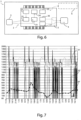
figure 5 shows a diagram of a device for reading and controlling the gas that is the object of the present invention; -
figure 6 shows a diagram of a device for reading and controlling the gas supply that is the object of the present invention; -
figure 7 shows a graph corresponding to values measured by a plurality of sensors of a device object of the present invention; -
figure 8 shows a top view of the device infigure 3 , where the inlet and outlet connectors of the gas supply connectors are shown. - In the various figures the similar parts will be indicated with the same numerical references.
- A common gas meter, as part of the prior art, does not provide the possibility of storing time series of measurements relating to the operation of the gas network near the meter. As can be seen from
figure 1 , in order to store time series of measurements relating to the operation of the gas network near the meter 1', it is necessary to modify a portion of the pipe connected to the meter 1', for example, by means of a special connector 100', to which an additional device must be connected. - Said further device, also known, can be a data-logger 200', which allows storing values, for example, of the pressure measured at regular intervals and for a predefined period of time, and communicating remotely with the distribution network manager.
- The device of the present invention is essentially a
device 1, for reading and controlling the gas supply, in which aninput connector 11 and anoutput connector 12 are obtained of a pipe in which gas flows from a distribution network towards at least one residential user, comprising acontrol logic unit 2 for the operation of saiddevice 1, and for storing predetermined threshold values, comprising a plurality ofsensors 3, operatively connected to saidcontrol logic unit 2, for measurement of values of physical quantities and sending them to saidcontrol logic unit 2, a gassupply blocking member 4, operatively connected to saidcontrol logic unit 2, saidcontrol logic unit 2 being configured to compare said values measured and received by said plurality ofsensors 3 with said predetermined threshold values, to send alarm signals and to activate said blockingmember 4 to block the gas supply, if said measured values are higher than said values of the predetermined thresholds. - Referring to
figure 3 , thedevice 1 essentially comprises afirst housing 10 and asecond housing 13 communicating with each other. - Said
first housing 10 has on its external surface aninput connector 11 and anoutput connector 12 of a pipe in which gas flows from a distribution network towards residential users, and internally includes the gas pipe, a blockingmember 4 for closing the gas supply, and one or more sensors of said plurality ofsensors 3. - Said
first housing 10 is preferably made of pressed steel, or polymeric material, in order to guarantee high resistance to corrosion, both external and internal, resistance to high operating temperatures, and high hydraulic tightness, for example, to withstand a pressure of at least 0.5 bar. - The
second housing 13 includes thecontrol logic unit 2 and a power supply. - In some embodiments, the
second housing 13 also contains a plurality ofsensors 3 and atransceiver unit 5, operationally connected to the control logic unit. - In some embodiments, the
second housing 13 includes, on one of its external surfaces, anoptical display 6, for example, a display to display the data or values measured by thesensors 3, and a reset button 7. - Furthermore, the
device 1 can include a door to access the internal part of saidsecond housing 13, so as to be able to replace the sensors of said plurality ofsensors 3 or saidcontrol logic unit 2, if a failure or excessive use occurs of the same. - With reference to
figure 5 , thecontrol logic unit 2 comprises anaccess module 21, afirst comparison module 22, arecording module 23, aprocessing module 24, asecond comparison module 25, aninterruption module 26, and areopening module 27. - In particular, said
control logic unit 2 is a PLC - programmable logic controller type processor, i.e. a computer for industrial use adapted to the control and execution of processes of components controlled by it. - The threshold
value access module 21 is configured to receive or read, from an archive, predetermined first and/or second threshold values. - Said
access module 21 interacts with an archive where the values measured and sent by said plurality ofsensors 3 and the first threshold values are stored, for example, pre-established values of normal operation of saiddevice 1, such as pressure, flow, and temperature. - The
first comparison module 22 is configured to receive the values measured by said plurality ofsensors 3 and compare them with the first predetermined threshold values, received from theaccess module 21, which thecomparison module 22 accesses. - The
recording module 23 is operationally connected to the plurality ofsensors 3, to record one or more time series of said values measured by each sensor of saidplurality 3. - In particular, the recording duration, i.e. the time during which to record a series and/or the recording frequency, i.e. the time interval between two different detections of the same sensor, are configurable using the
recording module 23. - For example, it is possible to record the data detected by the sensors every second during an hour if a component has been changed, for example, a joint, a valve or similar, in order to verify the correct installation of the component.
- Similarly, the
recording module 23 can be configured to log sensor data, for example, every three hours during a week to monitor gas supply following an outage. In this way, the recording of time series is managed in such a way as to record a greater number of data where necessary and to reduce the number of recorded data so as not to saturate the data archive to which theaccess module 21 has accessed. An example of data acquisition from a plurality of sensors, as shown infigure 7 , will be described below. - The
processing module 24 is configured to process said one or more time series recorded by saidrecording module 23. - In this description, processing one or more time series is to be understood as performing mathematical operations with said time series. Examples of these mathematical operations include calculating the average of the values measured by a sensor during a given time interval or excluding an outlier, i.e., a value outside the range of acceptable values for a given sensor.
- Said processing module can be configured to process a plurality of time series each corresponding to a sensor of said plurality of
sensors 3 in such a way as to combine said time series and define a parameter to be compared with a second threshold value. - In this way, the calculation of the parameters to be compared is not limited to a single sensor, or to multiple sensors of the same type, but can define a parameter based on the processing of various physical quantities, which cooperate or coexist to decide whether it is necessary to stop the gas supply or if it is safe to proceed with the supply itself.
- The
second comparison module 25 is configured to compare said one or more time series recorded by therecording module 23, and possibly processed by theprocessing module 24, with said second predetermined threshold values. - The
interruption module 26 is a module of thecontrol logic unit 2 capable of communicating with theblocking device 2. - In particular, the
interruption module 26 is configured to send an alarm signal and activate said blockingdevice 4 to block the gas supply, if said values measured by thesensors 3 are higher than said first predetermined threshold values. - In some embodiments, the
control logic unit 2 sends, for example through theinterruption module 26, the alarm signal to adisplay 6 to facilitate alarm information to the user. - The
interruption module 26 activates the blockingmember 4, for example, via thetransceiver unit 5, as described below. - Specifically, the blocking
member 4 is a solenoid valve capable of blocking or allowing the flow of gas towards the residential network. - The reopening
module 27 is configured to send an inhibition command of said blockingmember 4 to inhibit said blockingmember 4 and allow the supply of gas, if said measured values are higher than said first predetermined threshold values and if the values obtained from a processing of said one or more series, by means of said processing module, are lower than said second predetermined threshold values. - The presence of the reopening
module 27 is advantageous as it allows the gas pipe to deliver gas to the users in the presence of an alert signal corresponding to a value outside the permitted range which does not last over time. In fact, if a temperature value is above a maximum temperature at a certain moment, it is possible to verify that this temperature has returned to an admissible value before blocking the gas supply. - In this way, greater stability is guaranteed and interruptions due to the presence of outliers in the sensor measurement are limited. For example, it is possible to define a first threshold value for the maximum range of 6 m3/h and define a second threshold value for the maximum range equal to 7.2 m3/h, where said second threshold value corresponds to the rate at which the network is overloaded. This second threshold value is relevant when evaluating the gas supply over time. In fact, using the reopening
module 27 it is possible to maintain the gas supply even when measuring a range greater than 6 m3/h for a certain time interval, provided that said measured flow rate does not exceed the second value of 7.2 m3/h in that time interval. - Furthermore, since the
processing module 24 allows one or more time series to be processed and since thecomparison module 25 can compare one or more time series with one or more of said first threshold values, it is possible to combine one or more values and one or multiple time series obtained from sensors of different nature to decide whether to block the supply. - Combining one or more values and one or more time series obtained from sensors of different natures to decide whether to block the supply includes, for example, that the
interruption module 26 sends a blocking signal to the blockingmember 4 if the measured flow rate from a sensor inside the pipe is greater than 6 m3/h and the pressure measured in the pipe is greater than 32 mbar. - Without departing from the scope of protection of the invention, the first and second threshold values can also include minimum threshold values to be respected. An example of the first minimum threshold value for pressure is a value equal to 13 mbar.
- With reference to the plurality of
sensors 3, thedevice 1 includes the following types of sensors: apressure sensor 31, aflow sensor 32, a seismic sensor 33, and atemperature sensor 34. - One or
more pressure sensors 31 are arranged inside thefirst housing 10, and measure the gas supply pressure both in thegas inlet section 11 and in thegas outlet section 12. - Specifically, when the blocking
member 4 is closed, the supply is blocked and, therefore, saidpressure sensor 31 detects the pressure of the residential user circuit. - When said blocking
member 4 is open, the gas flows through the pipe, and saidpressure sensor 31 detects the pressure of the distribution network. - The
flow sensor 32 is arranged inside thefirst housing 10 and is able to continuously control the flow of gas flowing in the tube. - The
flow sensor 32 is able to measure mixtures of methane gas with other gases of different nature, such as, for example, synthetic methane, biomethane, and hydrogen. - The presence of a
flow sensor 32 with said characteristics makes thedevice 1 versatile and compatible with a plurality of gas mixtures. - The
flow sensor 32 is preferably an ultrasonic sensor arranged in contact with the gas in the outlet portion of the gas tube. - Some examples of the
device 1 provide an integrated sensor that includes theflow sensor 32 and thetemperature sensor 34. - In some examples, an integrated ultrasonic sensor sends waves into the gas pipe and detects the flow rate, the time the gas passes through the sensor, the temperature and samples these values with a defined period, i.e., at regular intervals. Examples of the sampling period are every 125 ms or every 250 ms.
- Without departing from the scope of protection, the
control logic unit 2 is able to define a sampling period different from those described above. - The
temperature sensor 34 is able to send the measured values to saidcontrol logic unit 2 which carries out a comparison with a predefined threshold temperature value, stored in said archive and accessible via theaccess module 21 of saidcontrol logic unit 2. - In particular, said
temperature sensor 34, in contact with the gas, is used to correctly account for the quantity of gas flowing through thedevice 1 and can be used to detect potential fires, for example when the temperature is above 80 °C . - The plurality of
sensors 3 can include a further environmental pressure sensor, a smoke or flame sensor, a hygrometer, and the like, which can be integrated together or each connected to thecontrol logic unit 2. - In some embodiments, the plurality of
sensors 3 comprises one or more sensors capable of detecting a tampering attempt. - In particular, using an accelerometer or a seismic sensor it is possible to verify whether the
device 1, or a part of it, for example, the meter, has been removed without authorization. In fact, a non-zero value of said sensors can indicate thatdevice 1 has been removed. - Additionally, tampering can be confirmed by reading a pressure sensor. In particular, the plurality of
sensors 3 can include a pressure sensor arranged outside thedevice 1 to monitor that thedevice 1 remains in the installation position and recognize when thedevice 1 is disconnected from the network and, therefore, to identify an attempt of tampering, which corresponds to a zero relative pressure value. - The
transceiver unit 5 described above is operationally connected with saidcontrol logic unit 2, to which it is connected physically, or via wireless connection, for example, ZigBee, Wi-fi, Bluetooth, or the like. - The
transceiver unit 5 includes at least a remote communication modem, an antenna, and a local communication port, or the like. - The
transceiver unit 5 communicates in real time to the outside of thedevice 1, or sends data packets of predefined sizes. - Sending packets can be encoded to save the time of sending and a unique device identification code. Examples of this code include a digital signature that corresponds to each device or the device's serial number.
- This allows gas consumption to be read remotely, without requiring the intervention of an operator, and also to carry out the transmission of delivery parameters and any malfunction or dangerous situation.
- The power supply is preferably a battery and may include a charge status indicator.
- The operation of the
device 1 described above is as follows. - The plurality of
sensors 3 measures the values and sends them to thefirst comparison module 22 and to therecording module 23. - The first comparison module uses the values received from the plurality of sensors to compare each of said values with a respective first threshold that the comparison module receives from the
access module 21, which accesses an archive, for example, a database or a table of predefined values for each of the quantities measured by the sensors. - As a general rule, if said values detected by said plurality of
sensors 3 are higher than said first predetermined threshold values, then thecontrol logic unit 2, through theinterruption module 26, closes the blockingmember 4 thus interrupting the gas supply. - In some embodiments, the
interruption module 26 also sends an alarm signal to be displayed on thedisplay 6, which will differ based on the type of anomaly. - The
recording module 23, operationally connected to the plurality ofsensors 3, records one or more time series of said values measured by each sensor and communicates with the processing module, to which it sends said one or more time series. - Starting from the received time series, the
processing module 24 performs series processing, i.e. one or more mathematical operations on said series. These mathematical operations, as described above, include the arithmetic mean, the median, the maximum, the minimum, the creation of indirect parameters that combine the values of two or more physical quantities measured by the plurality ofsensors 3. - At this point, it is possible to compare the processed time series, or equivalently the parameters deriving from them, with second predetermined threshold values, which serve to determine whether an action of the
interruption module 26 is to be inhibited. In fact, the comparison between the processed time series and the second threshold values allows the blocking device not to be closed even though a sensor can measure a value greater than the first predetermined threshold, as long as a second condition is respected, i.e., that the corresponding time series does not is greater than the second predetermined threshold. - Thanks to the presence of the
interruption module 26, thecontrol logic unit 2 is able to detect potential gas leaks inside the pipe of a residential user, both during the installation phase and during normal use, and thanks to the reopeningmodule 27. thecontrol logic unit 2 will be able to ignore the supply stop signals if the dispersions are negligible or last such a limited time that they are not dangerous or increase consumption. - With reference to
figure 7 , the values measured by a plurality ofsensors 3 including apressure sensor 31, aflow rate sensor 32, and atemperature sensor 34 reported every three hours and thirty minutes are shown. The data in the following table correspond to the values measured by the sensors in the graph infigure 7 and reported below with a frequency of fifteen minutes during twelve hours:Time Flow rate (dm3/h) Temperature (°C) Pressure(mbar) 11:15 0 3 23,7 11:30 0,66 3,12 23,8 11:45 0 3,18 23,9 12:00 0,08 3,31 24,1 12:15 0 3,31 24,3 12:30 0 3,37 24,5 12:45 0 3,5 24,8 13:00 0 3,62 25,2 13:15 0 3,75 25,8 13:30 0 3,93 26,1 13:45 0 4,12 26,4 14:00 0 4,31 18,5 14:15 2367,26 4,56 17,8 14:30 1563,65 4,81 18,6 14:45 1385,62 5 17,6 15:00 0 5,12 19 15:15 1382,92 5,25 18,2 15:30 0,13 5,37 22,7 15:45 0 5,43 20,5 16:00 0 5,5 22,7 16:15 0 5,56 22,7 16:30 4,5 5,56 18,6 16:45 0 5,5 22,1 17:00 0 5,5 19,5 17:15 0 5,5 20,5 17:30 0 5,43 18,9 17:45 0 5,43 18,8 18:00 0 5,37 22,4 18:15 0 5,31 23 18:30 0,08 5,31 22,9 18:45 0 5,25 23 19:00 1881,11 5,18 18,1 19:15 1387,54 5,12 18,4 19:30 1589,18 5,12 22,8 19:45 1398,46 5,12 17,8 20:00 1382,91 5,12 18 20:15 0 5,12 20 20:30 0 5,12 22,9 20:45 1407,04 5,06 17,8 21:00 1384,58 5,06 17,8 21:15 1386,16 5 18,2 21:30 0 5 20,9 21:45 2,47 5 18,5 22:00 0 5 22,6 22:15 0 5 18,7 22:30 1389,6 5 18,5 22:45 1172,97 5 17,3 23:00 1390,2 4,93 17,8 23:15 0,21 4,93 22,3 23:30 1398,92 4,87 17,9 - The
device 1 allows managing the gas supply based on one or more sensors of said plurality ofsensors 3. - The operation of the
device 1 is described below as a function of the values measured by apressure sensor 31. - If a
pressure sensor 31, arranged near the outlet section of the pipe, detects a sudden drop in pressure of the gas flow, for example due to a leak, such that the pressure variation is greater than a first threshold of pressure variation and a second pressure variation threshold, theinterruption module 26 sends to said blockingmember 4 instructions for closing the gas supply. - The operator or user, after having verified that all domestic gas appliances are closed, can then press a reset button, which is preferably arranged on the external surface of said
second housing 13. - At this point, said
control logic unit 2 checks for any gas leaks on the residential user. - If the
pressure sensor 31 detects a further drop in pressure, saidcontrol logic unit 2 commands the closing of said blockingmember 4. - Furthermore, the
control logic unit 2 sends an alarm message to thedisplay 6 which projects it. - If the user has properly shut off the gas utilities, this additional drop in pressure is actually an indication of a leak or malfunction in a gas utility.
- Otherwise, if a further drop in pressure does not occur, having therefore verified that the
device 1 is hermetically closed on the user, saidcontrol logic unit 2 commands the reopening of saidblocking device 4. - If the
pressure sensor 31 is arranged in proximity to the distribution network, it can detect a pressure drop on the gas distribution network, for example, due to a malfunction on the network. - Therefore, in case of a malfunction on the distribution network, the
logic control units 2 of thevarious devices 1 connected to the network in which the malfunction was detected, close thecorresponding blocking devices 4 and send the alarm signals to a control center. - When the malfunction is repaired, the user or the distribution network operator, after verifying that the gas utilities are turned off, presses the reset button.
- Said
control logic unit 2 then verifies the state of the gas distribution network. - If the correct gas supply is verified, the
control logic unit 2 reopens the blockingmember 4. - In particular, using the
pressure sensor 31 it is possible to check the integrity of the user system when the blockingmember 4 is opened. - The procedure involves monitoring the pressure inside
device 1 for approximately two minutes. - If, within this period, the pressure is not within pre-established ranges, for example between 13 and 32 mbar, said blocking
member 4 is closed again. - From the moment of the reopening of said blocking
member 4 the following events occur: - after T0 seconds, the pressure P0 is measured;
- after other T1 seconds, the pressure P1 is measured;
- after other T2 seconds, the pressure P2 is measured.
- Said locking
member 4 remains open if both of the following conditions are verified: - 1. P0, P1, P2 ≥ minimum pressure Pmin (mbar), for example prefixed to the value of 13 mbar; and
- 2. P1-P2 < PD (mbar), prefixed to a value of 1 mbar, for example.
- It is also possible to check the pressure of the downstream distribution network, i.e., the pressure of the gas coming from the distribution network, by continuously monitoring it.
- When this falls below a first predefined threshold Prete_min, an alarm is generated and if during a certain time interval it is also below a second predefined threshold Prete'_min the blocking
member 4 is activated. - Furthermore, said
device 1 is also capable of performing the function of a data logger and allows the predetermined threshold values to be updated following the recordings of the time series by means of an update module. - The update is carried out using an update module capable of replacing the second predetermined threshold values with the second threshold values obtained from the processing of the time series recorded by the
logic unit 2. - In this way, it is possible to manage the gas supply dynamically, updating the threshold values based on an input from the network manager, extreme weather conditions, or variations external to the
device 1. - Therefore, the
device 1 can be remotely configured, through thetransceiver unit 5, to store the pressure values measured at regular intervals and for a predefined period of time. - The presence of the
pressure sensor 31 therefore makes it possible to continuously measure the relative pressures on the network. - The control of network pressures makes it possible, therefore, not only to certify the general state of efficiency of a low-pressure gas network, verifying compliance with the specifications of the relevant technical legislation but also to identify with great precision the areas in which the operating conditions can be critical long before this situation is detected by measurements pursuant to the UNI/TR 11631 standard and subsequent amendments and additions.
- Similarly to what is described above for the
pressure sensor 31, thedevice 1 manages the measurement of other sensors, such as aflow sensor 32 or atemperature sensor 34, and is able to work as a data logger also for the corresponding physical quantities to said sensors. - Without departing from the scope of protection, the
processing module 24 and thetransceiver unit 5 can be programmed to activate in the event of receiving a command or an anomalous measurement, so as to reduce the battery consumption of the device. - Similarly, the recording and updating modules can be programmed to allocate more memory when more frequent checking of the values measured by the sensors is required.
- The device of the present invention provides security and data recording functions that allow the installation of said device without requiring further support equipment.
- Furthermore, the device of the invention allows remote recording of data, avoiding the need for a highly specialized operator to go to the place where the device is installed to carry out the recording itself.
- If an anomaly is found, the device of the invention allows verifying both single measurements and series of measurements to determine the need to momentarily interrupt the gas supply downstream of the measurement point and possibly operate safely on the pipe.
- To install the device of the invention it is not necessary to operate on the network infrastructures. In particular, a standard connection is used from the network to the user without making any modifications and without requiring special joining pieces.
- The device has its own data access module and its own memory space on which to download or update the data and from which to read the data to compare with the measurements carried out by the
sensors 3. - The present invention has been described for illustrative but not limitative purposes, according to its preferred embodiments, but it is to be understood that modifications and/or changes can be introduced by those skilled in the art without departing from the relevant scope as defined in the enclosed claims.
Claims (16)
- Device (1), for reading and controlling the gas supply, wherein there is an input connector (11) and an output connector (12) of a pipe in which gas flows from a distribution network towards at least one residential user, comprising a control logic unit (2) for the operation of said device (1), which includesa plurality of sensors (3) operationally connected to said control logic unit (2), for measuring values of physical quantities,a gas supply blocking member (4), operationally connected to said control logic unit (2), whereinsaid control logic unit (2) includes:a threshold value access module (21) configured to receive, from an archive, first and/or second predetermined threshold values;a first comparison module (22) configured to compare said values measured by said plurality of sensors (3) with said first predetermined threshold values;a recording module (23), operatively connected to said plurality of sensors (3), configured to record one or more time series of said values measured by each sensor of said plurality (3);a processing module (24) configured to process said one or more time series recorded by said recording module;a second comparison module (25) configured to compare said one or more recorded time series with said second predetermined threshold values;an interruption module (26) configured to send an alarm signal and activate said blocking member (4) to block the gas supply, if said measured values are higher than said first predetermined threshold values; anda reopening module (27) configured to send an inhibition command of said blocking member (4) to inhibit said blocking member (4) and allow the gas supply, if said measured values are higher than said first predetermined threshold values and if the values obtained from a processing of said one or more series, by means of said processing module, are lower than said second predetermined threshold values.
- Device (1) according to claim 1, wherein said control logic unit (2) further comprisesa threshold module configured to determine additional second threshold values obtained from said one or more time series processed by said processing module, anda storage module configured to store, in said archive, said second threshold values obtained from said processing.
- Device (1) according to the preceding claim, wherein said control logic unit (2) comprises an update module for updating said second predetermined threshold values.
- Device (1) according to the preceding claim, wherein said updating module is capable of updating said second predetermined threshold values with said second threshold values obtained from said processing.
- Device (1) according to any of the previous claims, wherein said recording module is capable of saving said one or more time series in a dedicated memory space, which is accessible from said control logic unit (2).
- Device (1) according to any one of the preceding claims, wherein said recording module is capable of defining the frequency and the duration at which to record said one or more time series of said measured values.
- Device (1) according to any one of the preceding claims, wherein said processing module is configured to process a plurality of time series each corresponding to a sensor of said plurality of sensors (3), so as to combine said time series and define a parameter to compare with a second threshold value.
- Device (1) according to any one of the previous claims, comprising a display (6), operationally connected to said control logic unit (2), for displaying said measured values, said alarm signal, and/or said reopening control command.
- Device (1) according to any one of the preceding claims, whereinsaid plurality of sensors (3) comprises at least one of a flow, temperature, pressure and vibration sensor, and in whichsaid predetermined threshold values include predetermined threshold values of at least one of a threshold value of flow rate, temperature, pressure and vibration or a combination thereof.
- Device (1) according to any one of the preceding claims, wherein said plurality of sensors comprises a temperature sensor (34) arranged in contact with the gas for measuring the temperature of the gas itself.
- Device (1) according to any of the preceding claims, wherein said plurality of sensors comprises a pressure sensor (31), for detecting the gas supply pressure close to said inlet connector (11) and/or said output connector (12).
- Device (1) according to any of the preceding claims, wherein said plurality of sensors comprises a seismic sensor (33) for detecting higher vibrations.
- Device (1) according to any of the previous claims, comprising a transceiver unit (5), operationally connected to said control logic unit (2), for sending said alarm signal to a remote control unit and for receiving, from said remote control unit, commands and parameters for the operation of said control logic unit (2).
- Device (1) according to any of the preceding claims, wherein said plurality of sensors (3) comprises one or more sensors capable of detecting an attempt to tamper with said device (1).
- Computer program comprising instructions which, when the program is executed by a computer installed in a device (1) according to any of claims 1-14, cause the computer to execute the steps:A. measuring values of physical quantities using a plurality of sensors (3);B. receiving, from an archive, first and/or second predetermined threshold values;C. comparing said values measured according to step A with said first predetermined threshold values;D. recording one or more time series of said values measured by each sensor of said plurality of sensors (3);E. processing said one or more time series recorded according to step D;F. comparing said one or more recorded time series with said second predetermined threshold values;G. sending an alarm signal and activate said blocking member (4) to block the gas supply, if said measured values are higher than said first predetermined threshold values; andH. sending an inhibition command of said blocking member (4) to inhibit said blocking member (4) and allowing the supply of gas, if said measured values are higher than said first predetermined threshold values and if the values obtained according to step E are lower than said second predetermined threshold values.
- A computer-readable storage medium comprising instructions which, when executed by a computer, cause the computer to execute steps A-H according to the preceding claim.
Priority Applications (3)
| Application Number | Priority Date | Filing Date | Title |
|---|---|---|---|
| EP23425051.2A EP4506665A1 (en) | 2023-08-10 | 2023-08-10 | Device for reading and monitoring gas supply and operation method thereof |
| ES23425051T ES3027907T1 (en) | 2023-08-10 | 2023-08-10 | Device for reading and monitoring gas supply and operation method thereof |
| US18/799,835 US20250053164A1 (en) | 2023-08-10 | 2024-08-09 | Device for reading and controlling gas supply and its operating method |
Applications Claiming Priority (1)
| Application Number | Priority Date | Filing Date | Title |
|---|---|---|---|
| EP23425051.2A EP4506665A1 (en) | 2023-08-10 | 2023-08-10 | Device for reading and monitoring gas supply and operation method thereof |
Publications (1)
| Publication Number | Publication Date |
|---|---|
| EP4506665A1 true EP4506665A1 (en) | 2025-02-12 |
Family
ID=88838797
Family Applications (1)
| Application Number | Title | Priority Date | Filing Date |
|---|---|---|---|
| EP23425051.2A Pending EP4506665A1 (en) | 2023-08-10 | 2023-08-10 | Device for reading and monitoring gas supply and operation method thereof |
Country Status (3)
| Country | Link |
|---|---|
| US (1) | US20250053164A1 (en) |
| EP (1) | EP4506665A1 (en) |
| ES (1) | ES3027907T1 (en) |
Citations (5)
| Publication number | Priority date | Publication date | Assignee | Title |
|---|---|---|---|---|
| WO2006036513A1 (en) * | 2004-09-23 | 2006-04-06 | Lawrence Kates | System and method for utility metering and leak detection |
| IT201900006012A1 (en) * | 2019-04-18 | 2020-10-18 | Hera S P A | Device for reading and checking the gas supply, equipped with safety functions. |
| EP3688419B1 (en) * | 2017-09-25 | 2021-05-05 | Metersit S.r.l. | Sensor-valve assembly for gas meter, gas meter using the same and method for controlling a gas meter |
| US20220412787A1 (en) * | 2020-12-18 | 2022-12-29 | Itron, Inc. | Network edge detection and notification of gas pressure situation |
| WO2023034882A1 (en) * | 2021-08-31 | 2023-03-09 | Orbis Intelligent Systems, Inc. | Monitoring sites of a fluid delivery infrastructure |
-
2023
- 2023-08-10 EP EP23425051.2A patent/EP4506665A1/en active Pending
- 2023-08-10 ES ES23425051T patent/ES3027907T1/en active Pending
-
2024
- 2024-08-09 US US18/799,835 patent/US20250053164A1/en active Pending
Patent Citations (5)
| Publication number | Priority date | Publication date | Assignee | Title |
|---|---|---|---|---|
| WO2006036513A1 (en) * | 2004-09-23 | 2006-04-06 | Lawrence Kates | System and method for utility metering and leak detection |
| EP3688419B1 (en) * | 2017-09-25 | 2021-05-05 | Metersit S.r.l. | Sensor-valve assembly for gas meter, gas meter using the same and method for controlling a gas meter |
| IT201900006012A1 (en) * | 2019-04-18 | 2020-10-18 | Hera S P A | Device for reading and checking the gas supply, equipped with safety functions. |
| US20220412787A1 (en) * | 2020-12-18 | 2022-12-29 | Itron, Inc. | Network edge detection and notification of gas pressure situation |
| WO2023034882A1 (en) * | 2021-08-31 | 2023-03-09 | Orbis Intelligent Systems, Inc. | Monitoring sites of a fluid delivery infrastructure |
Also Published As
| Publication number | Publication date |
|---|---|
| US20250053164A1 (en) | 2025-02-13 |
| ES3027907T1 (en) | 2025-06-17 |
Similar Documents
| Publication | Publication Date | Title |
|---|---|---|
| KR101115522B1 (en) | system for managing gas security using wireless communication in building | |
| CN113075899B (en) | Gas leakage monitoring method based on intelligent gas meter of Internet of things | |
| US7921732B2 (en) | Method and an apparatus for operating an electromagnetic valve associated to a gas meter | |
| US20120031499A1 (en) | Method and Apparatus for Controlling Gas Flow via a Gas Shut-Off Valve Assembly | |
| IT201900006012A1 (en) | Device for reading and checking the gas supply, equipped with safety functions. | |
| EA024606B1 (en) | Clustered wellhead trunkline protection and testing system with esp speed controller and emergency isolation valve | |
| JP2004125609A (en) | Gas shut-off device | |
| EP2177884B1 (en) | Flow rate measuring apparatus and flow rate measuring method | |
| US20250053164A1 (en) | Device for reading and controlling gas supply and its operating method | |
| JP5162766B2 (en) | Gas meter | |
| US20210038936A1 (en) | Test Method and Test System for Testing a System for Monitoring the Protection Readiness of a Fire Protection Installation | |
| CN115560927B (en) | Gas leakage detection method and gas system | |
| JP4794831B2 (en) | Gas meter | |
| JP4722267B2 (en) | Gas shut-off device | |
| JP4304890B2 (en) | Shut-off device | |
| JP2009097948A (en) | Gas meter | |
| JP3221556B2 (en) | Anomaly detection device, anomaly detection method, and medium recording anomaly detection program | |
| JP3440780B2 (en) | Electronic gas meter | |
| JP2006017515A (en) | Gas meter | |
| JP2827811B2 (en) | Gas supply equipment abnormality monitoring device | |
| US12105543B2 (en) | Methods for safely restoring gas flow to a building from a remote location and related smart meters | |
| JP2006017508A (en) | Gas meter | |
| JP4224956B2 (en) | Gas shut-off device | |
| KR101012562B1 (en) | Power consumption management and reduction device using wired / wireless communication and home network | |
| JP4659401B2 (en) | Gas meter |
Legal Events
| Date | Code | Title | Description |
|---|---|---|---|
| PUAI | Public reference made under article 153(3) epc to a published international application that has entered the european phase |
Free format text: ORIGINAL CODE: 0009012 |
|
| STAA | Information on the status of an ep patent application or granted ep patent |
Free format text: STATUS: THE APPLICATION HAS BEEN PUBLISHED |
|
| AK | Designated contracting states |
Kind code of ref document: A1 Designated state(s): AL AT BE BG CH CY CZ DE DK EE ES FI FR GB GR HR HU IE IS IT LI LT LU LV MC ME MK MT NL NO PL PT RO RS SE SI SK SM TR |
|
| REG | Reference to a national code |
Ref country code: ES Ref legal event code: BA2A Ref document number: 3027907 Country of ref document: ES Kind code of ref document: T1 Effective date: 20250617 |
|
| STAA | Information on the status of an ep patent application or granted ep patent |
Free format text: STATUS: REQUEST FOR EXAMINATION WAS MADE |
|
| 17P | Request for examination filed |
Effective date: 20250723 |