EP4506650A1 - Plate heat exchanger - Google Patents
Plate heat exchanger Download PDFInfo
- Publication number
- EP4506650A1 EP4506650A1 EP24187705.9A EP24187705A EP4506650A1 EP 4506650 A1 EP4506650 A1 EP 4506650A1 EP 24187705 A EP24187705 A EP 24187705A EP 4506650 A1 EP4506650 A1 EP 4506650A1
- Authority
- EP
- European Patent Office
- Prior art keywords
- plate
- heat transfer
- heat exchanger
- fluid channel
- hole
- Prior art date
- Legal status (The legal status is an assumption and is not a legal conclusion. Google has not performed a legal analysis and makes no representation as to the accuracy of the status listed.)
- Pending
Links
Images



Classifications
-
- F—MECHANICAL ENGINEERING; LIGHTING; HEATING; WEAPONS; BLASTING
- F28—HEAT EXCHANGE IN GENERAL
- F28D—HEAT-EXCHANGE APPARATUS, NOT PROVIDED FOR IN ANOTHER SUBCLASS, IN WHICH THE HEAT-EXCHANGE MEDIA DO NOT COME INTO DIRECT CONTACT
- F28D9/00—Heat-exchange apparatus having stationary plate-like or laminated conduit assemblies for both heat-exchange media, the media being in contact with different sides of a conduit wall
- F28D9/0093—Multi-circuit heat-exchangers, e.g. integrating different heat exchange sections in the same unit or heat-exchangers for more than two fluids
-
- F—MECHANICAL ENGINEERING; LIGHTING; HEATING; WEAPONS; BLASTING
- F28—HEAT EXCHANGE IN GENERAL
- F28D—HEAT-EXCHANGE APPARATUS, NOT PROVIDED FOR IN ANOTHER SUBCLASS, IN WHICH THE HEAT-EXCHANGE MEDIA DO NOT COME INTO DIRECT CONTACT
- F28D9/00—Heat-exchange apparatus having stationary plate-like or laminated conduit assemblies for both heat-exchange media, the media being in contact with different sides of a conduit wall
- F28D9/0062—Heat-exchange apparatus having stationary plate-like or laminated conduit assemblies for both heat-exchange media, the media being in contact with different sides of a conduit wall the conduits for one heat-exchange medium being formed by spaced plates with inserted elements
- F28D9/0075—Heat-exchange apparatus having stationary plate-like or laminated conduit assemblies for both heat-exchange media, the media being in contact with different sides of a conduit wall the conduits for one heat-exchange medium being formed by spaced plates with inserted elements the plates having openings therein for circulation of the heat-exchange medium from one conduit to another
-
- F—MECHANICAL ENGINEERING; LIGHTING; HEATING; WEAPONS; BLASTING
- F28—HEAT EXCHANGE IN GENERAL
- F28D—HEAT-EXCHANGE APPARATUS, NOT PROVIDED FOR IN ANOTHER SUBCLASS, IN WHICH THE HEAT-EXCHANGE MEDIA DO NOT COME INTO DIRECT CONTACT
- F28D9/00—Heat-exchange apparatus having stationary plate-like or laminated conduit assemblies for both heat-exchange media, the media being in contact with different sides of a conduit wall
- F28D9/0031—Heat-exchange apparatus having stationary plate-like or laminated conduit assemblies for both heat-exchange media, the media being in contact with different sides of a conduit wall the conduits for one heat-exchange medium being formed by paired plates touching each other
- F28D9/0043—Heat-exchange apparatus having stationary plate-like or laminated conduit assemblies for both heat-exchange media, the media being in contact with different sides of a conduit wall the conduits for one heat-exchange medium being formed by paired plates touching each other the plates having openings therein for circulation of at least one heat-exchange medium from one conduit to another
- F28D9/005—Heat-exchange apparatus having stationary plate-like or laminated conduit assemblies for both heat-exchange media, the media being in contact with different sides of a conduit wall the conduits for one heat-exchange medium being formed by paired plates touching each other the plates having openings therein for circulation of at least one heat-exchange medium from one conduit to another the plates having openings therein for both heat-exchange media
-
- F—MECHANICAL ENGINEERING; LIGHTING; HEATING; WEAPONS; BLASTING
- F28—HEAT EXCHANGE IN GENERAL
- F28F—DETAILS OF HEAT-EXCHANGE AND HEAT-TRANSFER APPARATUS, OF GENERAL APPLICATION
- F28F17/00—Removing ice or water from heat-exchange apparatus
- F28F17/005—Means for draining condensates from heat exchangers, e.g. from evaporators
-
- F—MECHANICAL ENGINEERING; LIGHTING; HEATING; WEAPONS; BLASTING
- F28—HEAT EXCHANGE IN GENERAL
- F28F—DETAILS OF HEAT-EXCHANGE AND HEAT-TRANSFER APPARATUS, OF GENERAL APPLICATION
- F28F3/00—Plate-like or laminated elements; Assemblies of plate-like or laminated elements
- F28F3/08—Elements constructed for building-up into stacks, e.g. capable of being taken apart for cleaning
- F28F3/086—Elements constructed for building-up into stacks, e.g. capable of being taken apart for cleaning having one or more openings therein forming tubular heat-exchange passages
-
- F—MECHANICAL ENGINEERING; LIGHTING; HEATING; WEAPONS; BLASTING
- F28—HEAT EXCHANGE IN GENERAL
- F28F—DETAILS OF HEAT-EXCHANGE AND HEAT-TRANSFER APPARATUS, OF GENERAL APPLICATION
- F28F2265/00—Safety or protection arrangements; Arrangements for preventing malfunction
- F28F2265/06—Safety or protection arrangements; Arrangements for preventing malfunction by using means for draining heat exchange media from heat exchangers
-
- F—MECHANICAL ENGINEERING; LIGHTING; HEATING; WEAPONS; BLASTING
- F28—HEAT EXCHANGE IN GENERAL
- F28F—DETAILS OF HEAT-EXCHANGE AND HEAT-TRANSFER APPARATUS, OF GENERAL APPLICATION
- F28F2265/00—Safety or protection arrangements; Arrangements for preventing malfunction
- F28F2265/14—Safety or protection arrangements; Arrangements for preventing malfunction for preventing damage by freezing, e.g. for accommodating volume expansion
-
- F—MECHANICAL ENGINEERING; LIGHTING; HEATING; WEAPONS; BLASTING
- F28—HEAT EXCHANGE IN GENERAL
- F28F—DETAILS OF HEAT-EXCHANGE AND HEAT-TRANSFER APPARATUS, OF GENERAL APPLICATION
- F28F2265/00—Safety or protection arrangements; Arrangements for preventing malfunction
- F28F2265/22—Safety or protection arrangements; Arrangements for preventing malfunction for draining
Definitions
- the present disclosure relates to a plate heat exchanger.
- a traditional plate heat exchanger comprises a plurality of heat transfer plates. Fluid channels used for two or more fluids are formed between adjacent heat transfer plates so as to conduct heat exchange between two or more fluids.
- a purpose of the embodiments of the present disclosure is to provide a plate heat exchanger, thereby avoiding excessive water being remained in the plate heat exchanger when it is not in use, for example, so as to prevent freezing in the plate heat exchanger.
- An embodiment of the present disclosure provides a plate heat exchanger comprising: a plurality of heat transfer plates stacked in a first direction, wherein the heat transfer plate is configured to have a heat transfer plate edge on its side in a second direction perpendicular to the first direction; first and second fluid channels formed between adjacent heat transfer plates and fluidly isolated from each other; two first ports formed in the heat transfer plate on the side and an opposite other side of the heat transfer plate in the second direction, respectively, and fluidly communicated to the first fluid channel; and a hole formed in the heat transfer plate between one of the two first ports located on the side and the heat transfer plate edge in a second direction, which is fluidly communicated to the first fluid channel and fluidly isolated from the second fluid channel.
- the second direction is a vertical direction
- the hole is located in a bottom area of the plate heat exchanger in a state where the plate heat exchanger is being used.
- a distance between a wall portion of the hole proximate to the heat transfer plate edge and the heat transfer plate edge of the plate heat exchanger is in a range from 2 to 30 mm.
- a minimum cross-sectional area of the hole is in a range from 2 to 200 mm 2 .
- the hole is configured for having a temperature sensor installed therein.
- the plate heat exchanger further comprises a connecting tube fluidly communicated to the hole.
- the plate heat exchanger further comprises two cover plates between which the plurality of heat transfer plates are disposed, wherein the connecting tube is connected to each of the cover plates.
- the connecting tube is configured for having a detector installed therein, which is used to detect whether a heat exchange medium in the second fluid channel is leaked.
- the plate heat exchanger further comprises two second ports formed in the heat transfer plate on the side and the opposite other side of the heat transfer plate in the second direction, respectively, and fluidly communicated to the second fluid channel; and wherein the hole comprises one hole located between the one of the two first ports and one of the two second ports located on the side in a third direction perpendicular to the first and second directions.
- the plate heat exchanger further comprises a third fluid channel formed between adjacent heat transfer plates and fluidly isolated from the first and second fluid channels; two second ports formed in the heat transfer plate on the side and the opposite other side of the heat transfer plate in the second direction, respectively, and fluidly communicated to the second fluid channel; and two third ports formed in the heat transfer plate on the side and the opposite other side of the heat transfer plate in the second direction, respectively, and fluidly communicated to the third fluid channel.
- the hole is also fluidly isolated from the third fluid channel.
- the hole comprises two holes disposed on opposite sides of the one of the two first ports in a third direction perpendicular to the first and second directions, respectively, and between one of the two second ports located on the side and one of the two third ports located on the side.
- the first fluid channel is configured to use a refrigerating medium as the heat exchange medium
- the second fluid channel is configured to use a refrigerant as the heat exchange medium
- the hole in the bottom area of the plate heat exchanger for example, it is possible to avoid excessive water being remained in the plate heat exchanger when it is not in use, so as to prevent freezing in the plate heat exchanger.
- a plate heat exchanger 100 comprises: a plurality of heat transfer plates 2 stacked in a first direction D1, wherein the heat transfer plate 2 is configured to have a heat transfer plate edge 20 on its side in a second direction D2 perpendicular to the first direction D1 ( FIGS. 6 and 7 ); first and second fluid channels 11, 12 formed between adjacent heat transfer plates 2 and fluidly isolated from each other; and two first ports 31 formed in the heat transfer plate 2 on the side and an opposite other side of the heat transfer plate 2 in the second direction D2, respectively, and fluidly communicated to the first fluid channel 11.
- the plate heat exchanger 100 may further comprise: a third fluid channel 13 formed between adjacent heat transfer plates 2 and fluidly isolated from the first and second fluid channels 11,12; two second ports 32 formed in the heat transfer plate 2 on the side and the opposite other side of the heat transfer plate 2 in the second direction D2, respectively, and fluidly communicated to the second fluid channel 12; and two third ports 33 formed in the heat transfer plate 2 on the side and the opposite other side of the heat transfer plate 2 in the second direction D2, respectively, and fluidly communicated to the third fluid channel 13.
- the plate heat exchanger 100 may also comprise a connecting tube connected to the first port 31, the second port 32, and the third port 33, respectively.
- the plate heat exchanger 100 further comprises a hole 5, which is formed in the heat transfer plate 2 between the one of the two first ports 31 and the heat transfer plate edge 20 in the second direction D2.
- the hole 5 is fluidly communicated to the first fluid channel 11 and is fluidly isolated from the second fluid channel 12.
- the hole 5 is also fluidly isolated from the third fluid channel 13. The hole 5 is proximate to the heat transfer plate edge 20 in the second direction D2.
- the first fluid channel 11 is used for a first heat exchange medium
- the second fluid channel 12 is used for a second heat exchange medium
- the third fluid channel 13 is used for a third heat exchange medium.
- the first heat exchange medium may be a refrigerating medium, such as water, salt water, ethylene glycol, propylene glycol, and other liquids
- the second and third heat exchange media may be a refrigerant.
- the second and third heat exchange media may be the same as each other.
- the first heat exchange medium may also be a refrigerant.
- Plate heat exchanger 100 may be a soft brazed plate heat exchanger, a hard brazed plate heat exchanger, a gasket plate heat exchanger, or any other types of plate heat exchangers.
- the plate heat exchanger 100 may also comprise two cover plates 6 between which the plurality of heat transfer plates 2 are disposed; and a reinforcing plate disposed on each of the cover plates 6, wherein the connecting tube is installed on the reinforcing plate.
- the plate heat exchanger 100 may be the heat exchanger shown in FIGS. 1-3 , or a heat exchanger with only two first ports 31 and two second ports 32 (see FIG. 7 ), or other types of plate heat exchangers. Plate heat exchanger 100 may also be a double wall plate heat exchanger.
- the second direction D2 is a vertical direction
- the hole 5 is located in a bottom area of the plate heat exchanger 100 in a state where the plate heat exchanger 100 is being used.
- the plate heat exchanger 100 further comprises a connecting tube 4, which is fluidly communicated to the hole 5.
- the connecting tube 4 is connected to the cover plate 6.
- the hole 5 is configured for having a temperature sensor 9 installed therein.
- the connecting tube 4 may also be configured for having a detector installed therein, which is used to detect whether the heat exchange medium in the second fluid channel 12 is leaked, or which is used to detect whether the heat exchange medium in each of the second fluid channel 12 and the third fluid channel 13 is leaked.
- a distance between a wall portion 50 of the hole 5 proximate to the heat transfer plate edge 20 (or the lowest portion of a wall of the hole 5 in use) and the heat transfer plate edge 20 of the heat transfer plate 2 is in a range from 2 mm to 30 mm or 2 mm to 10 mm, etc.
- the minimum cross-sectional area of the hole 5 is in a range from 2 to 200 mm 2 or in a range from 2 to 50 mm 2 .
- the hole 5 comprises one hole 5 located between the one of the two first ports 31 and one of the two second ports 32 located on the side in a third direction D3 perpendicular to the first and second directions D1, D2. That is, the hole 5 is disposed between the first port 31 and the second port 32 located on the same side in the third direction D3.
- the hole 5 comprises two holes 5 disposed on opposite sides of the one of the two first ports 31 in a third direction D3 perpendicular to the first and second directions D1, D2, respectively, and the two holes 5 are located between one of the two second ports 32 located on the side and one of the two third ports 33 located on the side. That is, the two holes 5 are disposed between the first port 31 and the second port 32 located on the same side, and between the first port 31 and the third port 33 located on the same side in the third direction D3, respectively.
- the two holes 5 may be disposed symmetrically.
- the first heat exchange medium in the first fluid channel 11 of the plate heat exchanger 100 is water or saline
- some low-temperature environments such as below 0°C
- a level of the water or saline is higher than a safety limit
- the hole 5 it is possible to avoid excessive water being remained in the first fluid channel 11 of the plate heat exchanger 100, resulting in a decrease in the level of the water remained in the first fluid channel 11 of the plate heat exchanger 100. Therefore, the risk of the plate heat exchanger 100 being frozen and failed is relatively low.
- the temperature sensor 9 may be installed in the hole 5 so as to more accurately measure a temperature of the heat exchange medium in the first fluid channel 11 of the plate heat exchanger 100, thereby making a system associated with the plate heat exchanger 100 react more accurately.
- the detector may be installed in the connecting tube 4 so as to detect any leakage of the heat exchange medium in the second fluid channel 12. Therefore, it is possible to avoid polluting the environment with leaked harmful heat exchange medium.
- the connecting tube 4 may be connected to a harmful refrigerant collection bag or any system so as to prevent the harmful refrigerant from entering an atmosphere or a room, thereby avoiding further harm. Due to the installation of the detector in the connecting tube 4, it is possible to quickly detect a leakage of the harmful refrigerant.
- the connecting tube 4 is fluidly communicated to the hole 5.
- the connecting tube 4 is connected to the cover plate 6.
- a manual valve may be installed on the connecting tube 4 for manual drainage, or an electric control valve may be installed on the connecting tube 4 for an automatic control of drainage through operation of the system.
- any number of the holes 5 may be provided, for example, one, two, three, four or more holes 5, and the connecting tube 4 may be connected to any one or both of the two cover plates 6.
- the shape of the hole may be a circle, rectangle, triangle, trapezoid, square, ellipse, or any other shape.
- a temperature sensor is usually installed in the connecting tube connected to the first port 31 so as to avoid dynamic frozen problems.
- a temperature of the water in the connecting tube connected to the first port 31 is usually not the lowest temperature, while a temperature of the water in the hole 5 is much lower. Therefore, by installing the temperature sensor 9 in the hole 5 through the connecting tube 4, a lower temperature may be detected as a system logic input so as to avoid frozen risks.
- the temperature of the water at the water outlet is usually not the lowest temperature, while the temperature of the water at the drainage hole is much lower. Therefore, if the temperature sensor is installed in the hole 5 through the connecting tube, the lower temperature may be detected as the system logic input so as to avoid frozen risks.
Landscapes
- Engineering & Computer Science (AREA)
- Physics & Mathematics (AREA)
- Thermal Sciences (AREA)
- Mechanical Engineering (AREA)
- General Engineering & Computer Science (AREA)
- Heat-Exchange Devices With Radiators And Conduit Assemblies (AREA)
Abstract
Description
- This application claims the priority of Chinese Application No.
CN202310987792.5 filed on August 07, 2023 - The present disclosure relates to a plate heat exchanger.
- A traditional plate heat exchanger comprises a plurality of heat transfer plates. Fluid channels used for two or more fluids are formed between adjacent heat transfer plates so as to conduct heat exchange between two or more fluids.
- A purpose of the embodiments of the present disclosure is to provide a plate heat exchanger, thereby avoiding excessive water being remained in the plate heat exchanger when it is not in use, for example, so as to prevent freezing in the plate heat exchanger.
- An embodiment of the present disclosure provides a plate heat exchanger comprising: a plurality of heat transfer plates stacked in a first direction, wherein the heat transfer plate is configured to have a heat transfer plate edge on its side in a second direction perpendicular to the first direction; first and second fluid channels formed between adjacent heat transfer plates and fluidly isolated from each other; two first ports formed in the heat transfer plate on the side and an opposite other side of the heat transfer plate in the second direction, respectively, and fluidly communicated to the first fluid channel; and a hole formed in the heat transfer plate between one of the two first ports located on the side and the heat transfer plate edge in a second direction, which is fluidly communicated to the first fluid channel and fluidly isolated from the second fluid channel.
- According to an embodiment of the present disclosure, the second direction is a vertical direction, and the hole is located in a bottom area of the plate heat exchanger in a state where the plate heat exchanger is being used.
- According to an embodiment of the present disclosure, a distance between a wall portion of the hole proximate to the heat transfer plate edge and the heat transfer plate edge of the plate heat exchanger is in a range from 2 to 30 mm.
- According to an embodiment of the present disclosure, a minimum cross-sectional area of the hole is in a range from 2 to 200 mm2.
- According to an embodiment of the present disclosure, the hole is configured for having a temperature sensor installed therein.
- According to an embodiment of the present disclosure, the plate heat exchanger further comprises a connecting tube fluidly communicated to the hole.
- According to an embodiment of the present disclosure, the plate heat exchanger further comprises two cover plates between which the plurality of heat transfer plates are disposed, wherein the connecting tube is connected to each of the cover plates.
- According to an embodiment of the present disclosure, the connecting tube is configured for having a detector installed therein, which is used to detect whether a heat exchange medium in the second fluid channel is leaked.
- According to an embodiment of the present disclosure, the plate heat exchanger further comprises two second ports formed in the heat transfer plate on the side and the opposite other side of the heat transfer plate in the second direction, respectively, and fluidly communicated to the second fluid channel; and wherein the hole comprises one hole located between the one of the two first ports and one of the two second ports located on the side in a third direction perpendicular to the first and second directions.
- According to an embodiment of the present disclosure, the plate heat exchanger further comprises a third fluid channel formed between adjacent heat transfer plates and fluidly isolated from the first and second fluid channels; two second ports formed in the heat transfer plate on the side and the opposite other side of the heat transfer plate in the second direction, respectively, and fluidly communicated to the second fluid channel; and two third ports formed in the heat transfer plate on the side and the opposite other side of the heat transfer plate in the second direction, respectively, and fluidly communicated to the third fluid channel.
- According to an embodiment of the present disclosure, the hole is also fluidly isolated from the third fluid channel.
- According to an embodiment of the present disclosure, the hole comprises two holes disposed on opposite sides of the one of the two first ports in a third direction perpendicular to the first and second directions, respectively, and between one of the two second ports located on the side and one of the two third ports located on the side.
- According to an embodiment of the present disclosure, the first fluid channel is configured to use a refrigerating medium as the heat exchange medium, and the second fluid channel is configured to use a refrigerant as the heat exchange medium.
- According to an embodiment of the present disclosure, by disposing the hole in the bottom area of the plate heat exchanger, for example, it is possible to avoid excessive water being remained in the plate heat exchanger when it is not in use, so as to prevent freezing in the plate heat exchanger.
-
-
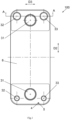
FIG. 1 is a schematic front view of a plate heat exchanger according to an embodiment of the present disclosure. -
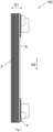
FIG. 2 is a side view of the plate heat exchanger shown inFIG. 1 ; -
FIG. 3 is a cross-sectional view of the plate heat exchanger shown inFIG. 1 taken along the AA line; -
FIG. 4 is a cross-sectional view of the plate heat exchanger shown inFIG. 1 taken along a straight line passing through an axis of the hole; -
FIG. 5 is a view showing a state of a temperature sensor being installed in the hole of the plate heat exchanger shown inFIG. 4 ; -
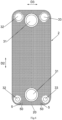
FIG. 6 is a front view of a heat transfer plate of the plate heat exchanger shown inFIG. 1 ; and -
FIG. 7 is a front view of a heat transfer plate of a plate heat exchanger according to an embodiment of the present disclosure. - The present invention will be described below in further detail in conjunction with the drawings and specific embodiments.
- Referring to
FIGS. 1 to 7 , aplate heat exchanger 100 according to an embodiment of the present disclosure comprises: a plurality ofheat transfer plates 2 stacked in a first direction D1, wherein theheat transfer plate 2 is configured to have a heattransfer plate edge 20 on its side in a second direction D2 perpendicular to the first direction D1 (FIGS. 6 and7 ); first andsecond fluid channels heat transfer plates 2 and fluidly isolated from each other; and twofirst ports 31 formed in theheat transfer plate 2 on the side and an opposite other side of theheat transfer plate 2 in the second direction D2, respectively, and fluidly communicated to thefirst fluid channel 11. - Referring to
FIGS. 1-3 and6 , in an embodiment of the present disclosure, theplate heat exchanger 100 may further comprise: athird fluid channel 13 formed between adjacentheat transfer plates 2 and fluidly isolated from the first andsecond fluid channels second ports 32 formed in theheat transfer plate 2 on the side and the opposite other side of theheat transfer plate 2 in the second direction D2, respectively, and fluidly communicated to thesecond fluid channel 12; and twothird ports 33 formed in theheat transfer plate 2 on the side and the opposite other side of theheat transfer plate 2 in the second direction D2, respectively, and fluidly communicated to thethird fluid channel 13. Theplate heat exchanger 100 may also comprise a connecting tube connected to thefirst port 31, thesecond port 32, and thethird port 33, respectively. - Referring to
FIGS. 6 to 7 , theplate heat exchanger 100 according to an embodiment of the present disclosure further comprises ahole 5, which is formed in theheat transfer plate 2 between the one of the twofirst ports 31 and the heattransfer plate edge 20 in the second direction D2. Referring toFIG. 5 , thehole 5 is fluidly communicated to thefirst fluid channel 11 and is fluidly isolated from thesecond fluid channel 12. For the plate heat exchanger shown inFIGS. 1-3 , thehole 5 is also fluidly isolated from thethird fluid channel 13. Thehole 5 is proximate to the heattransfer plate edge 20 in the second direction D2. - According to an embodiment of the present disclosure, the
first fluid channel 11 is used for a first heat exchange medium, thesecond fluid channel 12 is used for a second heat exchange medium, and thethird fluid channel 13 is used for a third heat exchange medium. The first heat exchange medium may be a refrigerating medium, such as water, salt water, ethylene glycol, propylene glycol, and other liquids, while the second and third heat exchange media may be a refrigerant. The second and third heat exchange media may be the same as each other. According to an embodiment of the present disclosure, the first heat exchange medium may also be a refrigerant. -
Plate heat exchanger 100 may be a soft brazed plate heat exchanger, a hard brazed plate heat exchanger, a gasket plate heat exchanger, or any other types of plate heat exchangers. Theplate heat exchanger 100 may also comprise twocover plates 6 between which the plurality ofheat transfer plates 2 are disposed; and a reinforcing plate disposed on each of thecover plates 6, wherein the connecting tube is installed on the reinforcing plate. - The
plate heat exchanger 100 may be the heat exchanger shown inFIGS. 1-3 , or a heat exchanger with only twofirst ports 31 and two second ports 32 (seeFIG. 7 ), or other types of plate heat exchangers.Plate heat exchanger 100 may also be a double wall plate heat exchanger. - Referring to
FIGS. 1-2 and4-7 , according to an embodiment of the present disclosure, the second direction D2 is a vertical direction, and thehole 5 is located in a bottom area of theplate heat exchanger 100 in a state where theplate heat exchanger 100 is being used. - Referring to
FIGS. 1-4 , according to an embodiment of the present disclosure, theplate heat exchanger 100 further comprises aconnecting tube 4, which is fluidly communicated to thehole 5. The connectingtube 4 is connected to thecover plate 6. Thehole 5 is configured for having atemperature sensor 9 installed therein. The connectingtube 4 may also be configured for having a detector installed therein, which is used to detect whether the heat exchange medium in thesecond fluid channel 12 is leaked, or which is used to detect whether the heat exchange medium in each of thesecond fluid channel 12 and thethird fluid channel 13 is leaked. - Referring to
FIGS. 6 and7 , according to an embodiment of the present disclosure, a distance between awall portion 50 of thehole 5 proximate to the heat transfer plate edge 20 (or the lowest portion of a wall of thehole 5 in use) and the heattransfer plate edge 20 of theheat transfer plate 2 is in a range from 2 mm to 30 mm or 2 mm to 10 mm, etc. The minimum cross-sectional area of thehole 5 is in a range from 2 to 200 mm2 or in a range from 2 to 50 mm2. - Referring to
FIG. 7 , according to an embodiment of the present disclosure, thehole 5 comprises onehole 5 located between the one of the twofirst ports 31 and one of the twosecond ports 32 located on the side in a third direction D3 perpendicular to the first and second directions D1, D2. That is, thehole 5 is disposed between thefirst port 31 and thesecond port 32 located on the same side in the third direction D3. - Referring to
FIG. 6 , according to an embodiment of the present disclosure, thehole 5 comprises twoholes 5 disposed on opposite sides of the one of the twofirst ports 31 in a third direction D3 perpendicular to the first and second directions D1, D2, respectively, and the twoholes 5 are located between one of the twosecond ports 32 located on the side and one of the twothird ports 33 located on the side. That is, the twoholes 5 are disposed between thefirst port 31 and thesecond port 32 located on the same side, and between thefirst port 31 and thethird port 33 located on the same side in the third direction D3, respectively. The twoholes 5 may be disposed symmetrically. - In the case where the first heat exchange medium in the
first fluid channel 11 of theplate heat exchanger 100 is water or saline, in some low-temperature environments such as below 0°C, if a level of the water or saline is higher than a safety limit, there is a risk that the water or saline may be frozen. By providing thehole 5, it is possible to avoid excessive water being remained in thefirst fluid channel 11 of theplate heat exchanger 100, resulting in a decrease in the level of the water remained in thefirst fluid channel 11 of theplate heat exchanger 100. Therefore, the risk of theplate heat exchanger 100 being frozen and failed is relatively low. In addition, thetemperature sensor 9 may be installed in thehole 5 so as to more accurately measure a temperature of the heat exchange medium in thefirst fluid channel 11 of theplate heat exchanger 100, thereby making a system associated with theplate heat exchanger 100 react more accurately. Furthermore, the detector may be installed in the connectingtube 4 so as to detect any leakage of the heat exchange medium in thesecond fluid channel 12. Therefore, it is possible to avoid polluting the environment with leaked harmful heat exchange medium. Additionally, in applications of some harmful refrigerants or drinking water, the connectingtube 4 may be connected to a harmful refrigerant collection bag or any system so as to prevent the harmful refrigerant from entering an atmosphere or a room, thereby avoiding further harm. Due to the installation of the detector in the connectingtube 4, it is possible to quickly detect a leakage of the harmful refrigerant. - According to an embodiment of the present disclosure, the connecting
tube 4 is fluidly communicated to thehole 5. The connectingtube 4 is connected to thecover plate 6. A manual valve may be installed on the connectingtube 4 for manual drainage, or an electric control valve may be installed on the connectingtube 4 for an automatic control of drainage through operation of the system. - According to an embodiment of the present disclosure, any number of the
holes 5 may be provided, for example, one, two, three, four ormore holes 5, and the connectingtube 4 may be connected to any one or both of the twocover plates 6. The shape of the hole may be a circle, rectangle, triangle, trapezoid, square, ellipse, or any other shape. - According to an embodiment of the present disclosure, when the
plate heat exchanger 100 is in an evaporator operation, a temperature sensor is usually installed in the connecting tube connected to thefirst port 31 so as to avoid dynamic frozen problems. However, a temperature of the water in the connecting tube connected to thefirst port 31 is usually not the lowest temperature, while a temperature of the water in thehole 5 is much lower. Therefore, by installing thetemperature sensor 9 in thehole 5 through the connectingtube 4, a lower temperature may be detected as a system logic input so as to avoid frozen risks. - Due to the installation of the
temperature sensor 9 in thehole 5, dynamic frozen problems may be avoided. However, the temperature of the water at the water outlet is usually not the lowest temperature, while the temperature of the water at the drainage hole is much lower. Therefore, if the temperature sensor is installed in thehole 5 through the connecting tube, the lower temperature may be detected as the system logic input so as to avoid frozen risks. - Although the present disclosure has been described in conjunction with embodiments, it is not limited to the aforementioned embodiments. For example, some embodiments and some technical features in all embodiments may be combined so as to form new embodiments.
Claims (13)
- A plate heat exchanger comprising:a plurality of heat transfer plates stacked in a first direction, wherein the heat transfer plate is configured to have a heat transfer plate edge on its side in a second direction perpendicular to the first direction;first and second fluid channels formed between adjacent heat transfer plates and fluidly isolated from each other;two first ports formed in the heat transfer plate on the side and an opposite other side of the heat transfer plate in the second direction, respectively, and fluidly communicated to the first fluid channel; anda hole formed in the heat transfer plate between one of the two first ports located on the side and the heat transfer plate edge in a second direction, which is fluidly communicated to the first fluid channel and fluidly isolated from the second fluid channel.
- The plate heat exchanger according to claim 1, wherein the second direction is a vertical direction, and the hole is located in a bottom area of the plate heat exchanger in a state where the plate heat exchanger is being used.
- The plate heat exchanger according to claim 1, wherein a distance between a wall portion of the hole proximate to the heat transfer plate edge and the heat transfer plate edge of the plate heat exchanger is in a range from 2 to 30 mm.
- The plate heat exchanger according to claim 1, wherein a minimum cross-sectional area of the hole is in a range from 2 to 200 mm2.
- The plate heat exchanger according to claim 1, wherein the hole is configured for having a temperature sensor installed therein.
- The plate heat exchanger according to claim 1, further comprising a connecting tube fluidly communicated to the hole.
- The plate heat exchanger according to claim 6, further comprising two cover plates between which the plurality of heat transfer plates are disposed, wherein the connecting tube is connected to each of the cover plates.
- The plate heat exchanger according to claim 6, wherein the connecting tube is configured for having a detector installed therein, which is used to detect whether a heat exchange medium in the second fluid channel is leaked.
- The plate heat exchanger according to claim 1, further comprising:two second ports formed in the heat transfer plate on the side and the opposite other side of the heat transfer plate in the second direction, respectively, and fluidly communicated to the second fluid channel; andwherein the hole comprises one hole located between the one of the two first ports and one of the two second ports located on the side in a third direction perpendicular to the first and second directions.
- The plate heat exchanger according to claim 1, further comprising:a third fluid channel formed between adjacent heat transfer plates and fluidly isolated from the first and second fluid channels;two second ports formed in the heat transfer plate on the side and the opposite other side of the heat transfer plate in the second direction, respectively, and fluidly communicated to the second fluid channel; andtwo third ports formed in the heat transfer plate on the side and the opposite other side of the heat transfer plate in the second direction, respectively, and fluidly communicated to the third fluid channel.
- The plate heat exchanger according to claim 10, wherein the hole is also fluidly isolated from the third fluid channel.
- The plate heat exchanger according to claim 10, wherein the hole comprises two holes disposed on opposite sides of the one of the two first ports in a third direction perpendicular to the first and second directions, respectively, and between one of the two second ports located on the side and one of the two third ports located on the side.
- The plate heat exchanger according to claim 1, wherein the first fluid channel is configured to use a refrigerating medium as the heat exchange medium, and the second fluid channel is configured to use a refrigerant as the heat exchange medium.
Applications Claiming Priority (2)
| Application Number | Priority Date | Filing Date | Title |
|---|---|---|---|
| CN202310987792.5A CN119509212A (en) | 2023-08-07 | 2023-08-07 | Plate Heat Exchanger |
| CN202322113633.0U CN220541818U (en) | 2023-08-07 | 2023-08-07 | Plate heat exchanger |
Publications (1)
| Publication Number | Publication Date |
|---|---|
| EP4506650A1 true EP4506650A1 (en) | 2025-02-12 |
Family
ID=91898766
Family Applications (1)
| Application Number | Title | Priority Date | Filing Date |
|---|---|---|---|
| EP24187705.9A Pending EP4506650A1 (en) | 2023-08-07 | 2024-07-10 | Plate heat exchanger |
Country Status (3)
| Country | Link |
|---|---|
| US (1) | US20250052509A1 (en) |
| EP (1) | EP4506650A1 (en) |
| MX (1) | MX2024008445A (en) |
Citations (4)
| Publication number | Priority date | Publication date | Assignee | Title |
|---|---|---|---|---|
| US6537506B1 (en) * | 2000-02-03 | 2003-03-25 | Cellular Process Chemistry, Inc. | Miniaturized reaction apparatus |
| US20220082448A1 (en) * | 2020-09-11 | 2022-03-17 | L'Air Liquide, Société Anonyme pour l'Etude et l'Exploitation des Procédés Georges Claude | Device for measuring temperatures in a heat exchanger |
| US20230036818A1 (en) * | 2020-01-30 | 2023-02-02 | Swep International Ab | A heat exchanger and refrigeration system and method |
| US20230041265A1 (en) * | 2020-01-30 | 2023-02-09 | Swep International Ab | Heat exchanger and refrigeration system and method |
Family Cites Families (8)
| Publication number | Priority date | Publication date | Assignee | Title |
|---|---|---|---|---|
| GB2208005A (en) * | 1987-08-07 | 1989-02-15 | Apv Uk | Plate heat transfer apparatus |
| US5462113A (en) * | 1994-06-20 | 1995-10-31 | Flatplate, Inc. | Three-circuit stacked plate heat exchanger |
| SE504799C2 (en) * | 1995-08-23 | 1997-04-28 | Swep International Ab | Triple circuit heat exchanger |
| SE518475C2 (en) * | 2001-02-20 | 2002-10-15 | Alfa Laval Ab | Flat heat exchanger with sensor device |
| US9163882B2 (en) * | 2011-04-25 | 2015-10-20 | Itt Manufacturing Enterprises, Inc. | Plate heat exchanger with channels for ‘leaking fluid’ |
| JP6097697B2 (en) * | 2011-11-11 | 2017-03-15 | 株式会社日阪製作所 | Plate heat exchanger |
| EP2674715A1 (en) * | 2012-06-14 | 2013-12-18 | Alfa Laval Corporate AB | A plate heat exchanger with thermally drilled hole |
| CN113295025A (en) * | 2021-05-26 | 2021-08-24 | 江苏宝得换热设备股份有限公司 | Double-sealing anti-leakage plate type heat exchanger with corner holes |
-
2024
- 2024-07-04 MX MX2024008445A patent/MX2024008445A/en unknown
- 2024-07-10 EP EP24187705.9A patent/EP4506650A1/en active Pending
- 2024-08-06 US US18/795,641 patent/US20250052509A1/en active Pending
Patent Citations (4)
| Publication number | Priority date | Publication date | Assignee | Title |
|---|---|---|---|---|
| US6537506B1 (en) * | 2000-02-03 | 2003-03-25 | Cellular Process Chemistry, Inc. | Miniaturized reaction apparatus |
| US20230036818A1 (en) * | 2020-01-30 | 2023-02-02 | Swep International Ab | A heat exchanger and refrigeration system and method |
| US20230041265A1 (en) * | 2020-01-30 | 2023-02-09 | Swep International Ab | Heat exchanger and refrigeration system and method |
| US20220082448A1 (en) * | 2020-09-11 | 2022-03-17 | L'Air Liquide, Société Anonyme pour l'Etude et l'Exploitation des Procédés Georges Claude | Device for measuring temperatures in a heat exchanger |
Also Published As
| Publication number | Publication date |
|---|---|
| MX2024008445A (en) | 2025-03-07 |
| US20250052509A1 (en) | 2025-02-13 |
Similar Documents
| Publication | Publication Date | Title |
|---|---|---|
| JP6641544B1 (en) | Plate heat exchanger and heat pump device provided with the same | |
| JP6615423B1 (en) | Plate heat exchanger, heat pump device equipped with plate heat exchanger, and heat pump air-conditioning / hot water supply system equipped with heat pump device | |
| US8826971B2 (en) | Micro-channel heat exchanger | |
| KR102430786B1 (en) | Integrated heat exchanger | |
| US20120011867A1 (en) | Multi-circuit heat exchanger | |
| US7073571B2 (en) | Integrated condenser oil cooler with a receiver/dryer | |
| CN103649668A (en) | Plate heater and refrigeration cycle device | |
| EP3392592A1 (en) | Inlet flow regulating structure and plate heat exchanger | |
| US10107532B2 (en) | Refrigerant evaporator having a tank external refrigerant space | |
| KR102829713B1 (en) | Heat exchangers, heat exchange assemblies, and thermal management systems | |
| EP4261489A1 (en) | Heat exchanger | |
| US5909766A (en) | Heat exchanger having a structure for detecting fluid leakage | |
| US20250052509A1 (en) | Plate heat exchanger | |
| CN113295025A (en) | Double-sealing anti-leakage plate type heat exchanger with corner holes | |
| CN220541818U (en) | Plate heat exchanger | |
| CN116804520A (en) | Thermal management integrated module and thermal management system | |
| CN119509212A (en) | Plate Heat Exchanger | |
| EP4357716B1 (en) | Plate heat exchanger with improved connection strength | |
| KR101511838B1 (en) | Fluidfluid heat exchager and heat exchange method using it | |
| KR100943573B1 (en) | Heat exchanger | |
| CN213747398U (en) | Condenser forming plate and condenser | |
| US20200393180A1 (en) | Accumulator and Heat Exchange Device Having Accumulator | |
| EP4509791A1 (en) | Plate heat exchanger | |
| JP4338591B2 (en) | Heat exchanger distributor | |
| EP4614096A1 (en) | Duct or vessel comprising a separating element |
Legal Events
| Date | Code | Title | Description |
|---|---|---|---|
| PUAI | Public reference made under article 153(3) epc to a published international application that has entered the european phase |
Free format text: ORIGINAL CODE: 0009012 |
|
| STAA | Information on the status of an ep patent application or granted ep patent |
Free format text: STATUS: THE APPLICATION HAS BEEN PUBLISHED |
|
| AK | Designated contracting states |
Kind code of ref document: A1 Designated state(s): AL AT BE BG CH CY CZ DE DK EE ES FI FR GB GR HR HU IE IS IT LI LT LU LV MC ME MK MT NL NO PL PT RO RS SE SI SK SM TR |
|
| STAA | Information on the status of an ep patent application or granted ep patent |
Free format text: STATUS: REQUEST FOR EXAMINATION WAS MADE |
|
| 17P | Request for examination filed |
Effective date: 20250728 |
|
| STAA | Information on the status of an ep patent application or granted ep patent |
Free format text: STATUS: EXAMINATION IS IN PROGRESS |
|
| 17Q | First examination report despatched |
Effective date: 20251015 |