EP4506610A1 - Lubricating device and a method for applying lubricant - Google Patents
Lubricating device and a method for applying lubricant Download PDFInfo
- Publication number
- EP4506610A1 EP4506610A1 EP23190743.7A EP23190743A EP4506610A1 EP 4506610 A1 EP4506610 A1 EP 4506610A1 EP 23190743 A EP23190743 A EP 23190743A EP 4506610 A1 EP4506610 A1 EP 4506610A1
- Authority
- EP
- European Patent Office
- Prior art keywords
- hose
- lubricating device
- lubricant
- nozzle
- dispensing area
- Prior art date
- Legal status (The legal status is an assumption and is not a legal conclusion. Google has not performed a legal analysis and makes no representation as to the accuracy of the status listed.)
- Granted
Links
Images


Classifications
-
- F—MECHANICAL ENGINEERING; LIGHTING; HEATING; WEAPONS; BLASTING
- F16—ENGINEERING ELEMENTS AND UNITS; GENERAL MEASURES FOR PRODUCING AND MAINTAINING EFFECTIVE FUNCTIONING OF MACHINES OR INSTALLATIONS; THERMAL INSULATION IN GENERAL
- F16N—LUBRICATING
- F16N7/00—Arrangements for supplying oil or unspecified lubricant from a stationary reservoir or the equivalent in or on the machine or member to be lubricated
- F16N7/38—Arrangements for supplying oil or unspecified lubricant from a stationary reservoir or the equivalent in or on the machine or member to be lubricated with a separate pump; Central lubrication systems
-
- F—MECHANICAL ENGINEERING; LIGHTING; HEATING; WEAPONS; BLASTING
- F16—ENGINEERING ELEMENTS AND UNITS; GENERAL MEASURES FOR PRODUCING AND MAINTAINING EFFECTIVE FUNCTIONING OF MACHINES OR INSTALLATIONS; THERMAL INSULATION IN GENERAL
- F16N—LUBRICATING
- F16N21/00—Conduits; Junctions; Fittings for lubrication apertures
-
- F—MECHANICAL ENGINEERING; LIGHTING; HEATING; WEAPONS; BLASTING
- F16—ENGINEERING ELEMENTS AND UNITS; GENERAL MEASURES FOR PRODUCING AND MAINTAINING EFFECTIVE FUNCTIONING OF MACHINES OR INSTALLATIONS; THERMAL INSULATION IN GENERAL
- F16L—PIPES; JOINTS OR FITTINGS FOR PIPES; SUPPORTS FOR PIPES, CABLES OR PROTECTIVE TUBING; MEANS FOR THERMAL INSULATION IN GENERAL
- F16L57/00—Protection of pipes or objects of similar shape against external or internal damage or wear
- F16L57/06—Protection of pipes or objects of similar shape against external or internal damage or wear against wear
-
- F—MECHANICAL ENGINEERING; LIGHTING; HEATING; WEAPONS; BLASTING
- F16—ENGINEERING ELEMENTS AND UNITS; GENERAL MEASURES FOR PRODUCING AND MAINTAINING EFFECTIVE FUNCTIONING OF MACHINES OR INSTALLATIONS; THERMAL INSULATION IN GENERAL
- F16N—LUBRICATING
- F16N2210/00—Applications
- F16N2210/34—Cables and wires
Definitions
- the present invention relates to the field of assembly processes. More specifically, the present invention relates to an assembly process for a motor vehicle product, especially a lubricating device for applying lubricant to a hose. Furthermore, the present invention relates to a method for applying lubricant to a hose.
- hoses used for the engine For the production of an engine of a motor vehicle it is necessary to lubricate hoses used for the engine. With lubricating the hoses, they can fit properly so that for example they do not disconnect upon start-up of the engine, which is classified as a high-risk problem because parts of the engine may be destroyed.
- hoses are lubricated by using a spray bottle. This process is not precisely traceable or accountable, though. To avoid for example disconnecting of hoses, as mentioned, it should be possible to make sure that all hoses on the engine line are lubricated correctly.
- a first aspect of the present invention relates to a lubricating device for applying lubricant to a hose.
- the lubricating device comprises a housing with a faceplate and a wall and at least one nozzle being arranged between these two, the faceplate and the wall which are in particular essentially parallel to one another.
- the at least one nozzle lubricant is capable of being dispensed into a dispensing area or lubricating area, and the faceplate having an opening, through which the hose is insertable into the dispensing area, wherein the hose is capable of being positioned by a guidance element during insertion into the dispensing area for applying the lubricant.
- the lubricating device comprises a pump unit or a pump, which is designed to convey the lubricant from a reservoir, in particular a tank and/or a supply connection, via the at least one nozzle into the dispensing area and the hose placed in the dispensing area.
- a lubricating machine which uses a pump and hose system, which interconnects the reservoir or tank with the nozzle, to spray lubricant from a main container or reservoir through a nozzle.
- the lubricating machine may be used to lubricate hoses before installation.
- a user puts the hose into the front plate or through the faceplate into the wall of the machine which activates the pump to spray the lubricant inside the hose or on the outside of the hose depending on application. This process can take less than a second, for example only 0.5 seconds.
- the guidance element may be formed via the opening or may be an extra element, in particular at the wall and corresponding to the opening.
- the machine may be used to lubricate a coolant tube adapter pipe hose.
- An associate brings the hose to the machine and presses against the plate.
- the machine will spray a soap or water mixture onto the inside O-ring of the coolant hose to ensure it fits on the engine connection correctly.
- the machine may communicate via BVIS to communicate that the hose lubrication was successful.
- At least one sensor device could be arranged at the lubricant device so that for example in the background the lubricant device or machine may measure a battery charge, if it is battery-operated, a level of lubricant in the reservoir, and may notify the associate via lights and sound when one of the levels is low.
- the lubricating device according to the invention may also be used to lubricate a variety of different objects, not just hoses. For example, bump stops on a door line could be lubricated via the lubricating device.
- the guidance element and/or at least a partial region of the wall are designed to be pressure-sensitive so that the pump unit is capable of being activated when pressure is applied to the guidance element and/or the partial region.
- the pump unit may be activated so that there is at least a spray of lubricant from the at least one nozzle.
- the guidance element and/or the wall may act as a switch for activating the pump.
- the at least one nozzle is arranged and/or has a shape such that the dispensing area is orientated or formed such that lubricant is applicable to an inside of the positioned hose and/or an outside of the positioned hose.
- the lubricating machine may be used to lubricate an inner side and/or an outer side of the hose, independently of how the nozzle is arranged or how the nozzle passing and leaving lubricant is formed or injected into the dispensing area. So the lubricating device could be advantageously used for both cases, lubricating the hose on its inside or outside without needing to switch to another device.
- At least two nozzles are presented and the supply of the lubricant at the at least two nozzles is controllable via a switch so that the at least one first nozzle of the at least two nozzles defines the dispensing area for application to the inside of the hose and the at least one second nozzle of the at least two nozzles defines a second dispensing area for application to the outside of the hose.
- the position of the hose is switchable between the at least first nozzle and the at least one second nozzle, which for example could be placed in such a way that the opening or inlet in the faceplate is for the at least first nozzle and another inlet or opening in the faceplate is for the at least one second nozzle.
- This means that the two dispensing areas are formed and via switching it is decided which dispensing area is used when activating the pump unit.
- An advantage of this approach is that it may be easily decided to lubricate either the inside or outside of the hose according to its intended use.
- a battery for supplying power to the pump unit so that the pump unit is operable independently of a power network, and the battery is arranged on or in the housing.
- an in particular, rechargeable battery and/or exchangeable battery is provided for operating the lubricating machine of the grid.
- At least one display element in particular a light bulb or display, and/or an acoustic element, in particular a speaker, are present which should output a filling level of the reservoir and/or a filling level of the battery.
- the lubricating device may comprise status lights for machine operation and liquid filling level, and a speaker may also be provided with an, in particular annoying, sound that is emitted when filling levels are very low.
- the housing of the lubricating device is mounted on a frame which has a mounting for the reservoir.
- the lubricating device comprises a frame so that it could be placed in such a way that the dispensing area is placed in a preferable location for the user.
- the reservoir in particular a tank, may be placed in the frame so that the housing for example can be very compact. This has the advantage that the lubricating device may be built with a compact design with a relatively large reservoir and the dispensing area may be placed as needed.
- the mounting for the reservoir is capable of being displaced so that the reservoir may be moved between a pumping position and a removal position.
- the reservoir is for example placed on a sliding platform within the frame of the lubricating device. This means that the reservoir may be moved by sliding between the pumping position, which is the position when the lubricating device is used for lubricating hoses, and the removal position for refilling the reservoir or tank or taking it out for replacing it by another one.
- the faceplate or at least a panel of the faceplate comprising the opening is exchangeable so that a diameter of the opening is adaptable to a diameter of the hose and/or the frame is decided to be adjustable in height.
- the opening of the faceplate could be changed accordingly by exchanging the faceplate or its panel.
- the frame's height is adjustable so that it could easily be used by workers who differ in height.
- the interface for data exchange with an external control device for example via a bus system for control
- the lubricating device has at least a communication device and/or an electronic unit such as a microcontroller (MCU), which is for example used for controlling a display element or the acoustic element and which may for example transmit a state of the lubricating device via the interface to an external control device for example an electronic control unit. Therefore, the process of applying lubricant via the lubricating device can be controlled or supervised.
- MCU microcontroller
- a second aspect of the present invention relates to a method for applying lubricant to a hose with a lubricating device, comprising a housing with a faceplate and a wall and at least one nozzle disposed between the faceplate and the wall, through which lubricant is dispensed into a dispensing area when the hose is inserted into the dispensing area through an opening in the faceplate, wherein the hose is positioned for application via a guidance element, which could be for example a power of the nozzle itself, upon insertion into the dispensing area, and a pump unit delivers or conveys the lubricant from a reservoir via the at least one nozzle into the dispensing area and therefore onto the hose.
- a guidance element which could be for example a power of the nozzle itself
- Fig. 1 showing a perspective view of a lubricating device 1 for applying lubricant to a hose.
- the lubricating device 1 comprises a housing 2 with a faceplate 3 and a wall 4 and at least one nozzle 5 being arranged between these two, the faceplate 3, and the wall 4. Through the at least one nozzle 5 lubricant is dispensable into a dispensing area 6 or dispensing zone.
- the faceplate 3 has an opening 7 or inlet through which the hose is insertable into the dispensing area 6 wherein the hose is positionable via a guidance element 8 or by means of the guidance element 8 during insertion into the dispensing area 6 for application or applying the lubricant.
- the lubricating device 1 further comprises a pump unit 9 in particular a pump, which is designed to convey the lubricant from a reservoir 10, in this example a tank, via a supply connection 11 and the at least one nozzle 5 into the dispensing area 6 or zone and therefore onto the part of the hose which needs to be lubricated.
- a pump unit 9 in particular a pump, which is designed to convey the lubricant from a reservoir 10, in this example a tank, via a supply connection 11 and the at least one nozzle 5 into the dispensing area 6 or zone and therefore onto the part of the hose which needs to be lubricated.
- FIG. 2 shows a side view of the lubricant device according to Fig. 1 where at least a partial region 12 of the wall 4 is designed to be pressure-sensitive so that the pump unit 9 is capable of being activated.
- the pressure-sensitiveness may be provided by a switch 24, which is positioned in line behind the wall 4 in the direction of inserting the hose so that the switch 24 is activated when pressure is exerted upon the partial region 12 or the wall 4.
- the switch 24 is in particular a micro switch.
- a pivot point for the wall or associated swivel plate can be provided to activate the micro switch by a minimal movement of the plate.
- a spring force of the micro switch can be low for easy handling.
- the guidance element 8 may be provided or formed by the opening 7 or may be an extra element at the wall 4.
- the guidance element 8 is used to place the hose in such a way into the dispensing area 6 that the spray of lubricant applied by the nozzle 5 reaches the part of the hose which should be lubricated. Therefore, a defined lubrication of the hose may be provided.
- the guidance element 8 may be pressure-sensitive and used for activation of the pump unit 9.
- the pump unit 9 is in particular a pump in the reservoir 10 or tank.
- the housing 2 is mounted onto a frame 13 which has a mounting 14 for the reservoir 10 or tank.
- the mounting 14 of the reservoir 10 is capable of being displaced or moved so that the reservoir is may be moved between a shown pumping position and a removal position.
- the mounting 14 may comprise for example a slide or rail system so that in the removal position the reservoir 10 may easily refilled or exchanged, wherein a refilled jug may be provided.
- the pump unit 9 is in particular a submersible pump inside the reservoir 10.
- the reservoir 10 may for example be provided with space for one gallon of lubricant.
- the connection of the housing 2 with the frame 13 or stand may be provided for example by four screws so that the housing 2 may easily be disconnected from the frame 13 or stand.
- the stand or frame 13 may be designed to be adjustable in height for easy operation or configuration of the lubricant device 1 as needed by a worker.
- a battery 15 could be provided by which the pump unit 9 is capable of being operated independently of the grid wherein the battery 15 is arranged on a second wall of the housing 2. It could also be arranged inside the housing 2.
- Fig. 3 shows a partial view of the housing 2 of the lubricating device 1 where the at least one nozzle 5 is shown as two nozzles for lubrication of the outer diameter of the hose. This means that a nozzle 5 for outside or outer diameter lubrication is shown wherein a spray area 16 is indicated which forms the dispensing area 6.
- Fig. 3 shows the housing without the faceplate 3 but with a holder 17 for the in particular exchangeable faceplate 3.
- the at least one nozzle 5 is arranged and/or has a shape so that the dispensing area 6 is orientated or formed in particular by the spray areas 17 so that lubricant is capable of being applied to an inside or an outside of the position hose.
- At least two nozzles 5 may be presented and the supply of the lubricant at the at least two nozzles is controllable by a switch so that the at least one first nozzle 5 of the at least two nozzles 5 defines the dispensing area 6 for application to the inside of the hose and the at least one second nozzle of the at least two nozzles 5 defines a second dispensing area for application to the outside of the hose.
- a control unit 22 within a box in the housing 2.
- the control unit could provide an interface for data exchange with an external control device, which is in particular an interface configured as a BVIS.
- Electric connectors 23 are provided for forming the interface between the external control unit and the control unit 22.
- Fig. 4 shows the at least one display element 18 and an acoustic element 19, for example a speaker, by which, in particular, a filling level of the reservoir 10, which is captured by a level sensor 20 in the reservoir 10, and a battery charging level of the battery 15 may be displayed or shown.
- the display element 18 may be configured more or less as a light bulb or a LED and/or also as a battery level indicator.
- Fig. 4 further shows another schematic side view of the housing 2.
- the panel 21 may built the guidance element 8, and is adaptable to a diameter of the hose which should be lubricated.
- hoses to be distinguished from the hoses to be lubricated
- pipes for connecting the reservoir 10 with supply connections 11 and the nozzles 5 Because of the modular setup of the lubricating device 1 these connecting pipes may easily be provided and adaptions may be easily made. All pipes need to connect the at least one nozzle 5 with the supply connections 11 and/or the tank may be hidden inside the housing 2.
- the connectors 23 may send data to the BVIS and/or receive data from the BVIS.
- the lubricating device 1 or spray unit is shown in Fig. 5 from a schematic back view where the placement of the connectors 23 is shown.
- a method for lubricating hoses could be provided.
- a hose is inserted into the dispensing area 6 through the openings 7 of the faceplate and wherein the positioning is performed via guidance element 8 and upon insertion the pump unit 9 is activated to dispense or spray the lubricant via the at least one nozzle 5.
- the sprayer box or housing 2 of the lubricating machine or lubricating device 1 may be used as stand-alone unit or together with a custom container.
Landscapes
- Engineering & Computer Science (AREA)
- General Engineering & Computer Science (AREA)
- Mechanical Engineering (AREA)
- Loading And Unloading Of Fuel Tanks Or Ships (AREA)
Abstract
Description
- The present invention relates to the field of assembly processes. More specifically, the present invention relates to an assembly process for a motor vehicle product, especially a lubricating device for applying lubricant to a hose. Furthermore, the present invention relates to a method for applying lubricant to a hose.
- For the production of an engine of a motor vehicle it is necessary to lubricate hoses used for the engine. With lubricating the hoses, they can fit properly so that for example they do not disconnect upon start-up of the engine, which is classified as a high-risk problem because parts of the engine may be destroyed.
- As of now, hoses are lubricated by using a spray bottle. This process is not precisely traceable or accountable, though. To avoid for example disconnecting of hoses, as mentioned, it should be possible to make sure that all hoses on the engine line are lubricated correctly.
- The disadvantages of the prior art are for example that it is not very industrialized and it could not be used for outer diameter lubrication. It has a low-capacity liquid container, so it requires frequent refilling. Furthermore, it requires a table mount.
- It is an object of the present invention to provide a lubricating device and a method for applying lubricant to a hose, which provides a simple method to lubricate hoses on the inner and/or outer diameter in a repeatable and reproducible way.
- This object is solved by a lubricating device and a method for applying lubricant to a hose according to the present invention. Advantageous embodiments are presented in the dependent claims, the description, and the drawings.
- A first aspect of the present invention relates to a lubricating device for applying lubricant to a hose. The lubricating device comprises a housing with a faceplate and a wall and at least one nozzle being arranged between these two, the faceplate and the wall which are in particular essentially parallel to one another. Through the at least one nozzle lubricant is capable of being dispensed into a dispensing area or lubricating area, and the faceplate having an opening, through which the hose is insertable into the dispensing area, wherein the hose is capable of being positioned by a guidance element during insertion into the dispensing area for applying the lubricant. Furthermore, the lubricating device comprises a pump unit or a pump, which is designed to convey the lubricant from a reservoir, in particular a tank and/or a supply connection, via the at least one nozzle into the dispensing area and the hose placed in the dispensing area.
- In other words, a lubricating machine is presented, which uses a pump and hose system, which interconnects the reservoir or tank with the nozzle, to spray lubricant from a main container or reservoir through a nozzle. This lubricates for example the rubber O-ring on the inside of hoses.
- The lubricating machine may be used to lubricate hoses before installation. A user puts the hose into the front plate or through the faceplate into the wall of the machine which activates the pump to spray the lubricant inside the hose or on the outside of the hose depending on application. This process can take less than a second, for example only 0.5 seconds. The guidance element may be formed via the opening or may be an extra element, in particular at the wall and corresponding to the opening.
- The machine may be used to lubricate a coolant tube adapter pipe hose. An associate brings the hose to the machine and presses against the plate. The machine will spray a soap or water mixture onto the inside O-ring of the coolant hose to ensure it fits on the engine connection correctly. Once the spray application is complete, the machine may communicate via BVIS to communicate that the hose lubrication was successful.
- At least one sensor device could be arranged at the lubricant device so that for example in the background the lubricant device or machine may measure a battery charge, if it is battery-operated, a level of lubricant in the reservoir, and may notify the associate via lights and sound when one of the levels is low. The lubricating device according to the invention may also be used to lubricate a variety of different objects, not just hoses. For example, bump stops on a door line could be lubricated via the lubricating device.
- It is an advantage of the present invention that lubricating a large number of hoses, for example in a production process, each is lubricated exactly in the same way. As a result the reproducibility is high. Therefore, the quality of the process is also high.
- In an embodiment of the present invention the guidance element and/or at least a partial region of the wall are designed to be pressure-sensitive so that the pump unit is capable of being activated when pressure is applied to the guidance element and/or the partial region. In other words, by inserting the hose into the dispensing area, and touching the wall, or moving the guidance element, the pump unit may be activated so that there is at least a spray of lubricant from the at least one nozzle. The guidance element and/or the wall may act as a switch for activating the pump. An advantage is that the user does not need to activate the lubricating process for example via an extra switch with his second arm. This means the lubrication process may be activated automatically when the hose is placed correctly in the dispensing area.
- In another embodiment of the present invention, the at least one nozzle is arranged and/or has a shape such that the dispensing area is orientated or formed such that lubricant is applicable to an inside of the positioned hose and/or an outside of the positioned hose. In other words, the lubricating machine may be used to lubricate an inner side and/or an outer side of the hose, independently of how the nozzle is arranged or how the nozzle passing and leaving lubricant is formed or injected into the dispensing area. So the lubricating device could be advantageously used for both cases, lubricating the hose on its inside or outside without needing to switch to another device.
- At least two nozzles are presented and the supply of the lubricant at the at least two nozzles is controllable via a switch so that the at least one first nozzle of the at least two nozzles defines the dispensing area for application to the inside of the hose and the at least one second nozzle of the at least two nozzles defines a second dispensing area for application to the outside of the hose. In other words, the position of the hose is switchable between the at least first nozzle and the at least one second nozzle, which for example could be placed in such a way that the opening or inlet in the faceplate is for the at least first nozzle and another inlet or opening in the faceplate is for the at least one second nozzle. This means that the two dispensing areas are formed and via switching it is decided which dispensing area is used when activating the pump unit. An advantage of this approach is that it may be easily decided to lubricate either the inside or outside of the hose according to its intended use.
- In still another embodiment of the present invention a battery is provided for supplying power to the pump unit so that the pump unit is operable independently of a power network, and the battery is arranged on or in the housing. In other words, an in particular, rechargeable battery and/or exchangeable battery is provided for operating the lubricating machine of the grid. An advantage is that the lubricating machine may be used in a portable manner and may be placed at a destination where it is needed, without the need of a connection to a power network.
- In yet another embodiment of the present invention at least one display element, in particular a light bulb or display, and/or an acoustic element, in particular a speaker, are present which should output a filling level of the reservoir and/or a filling level of the battery. In other words, the lubricating device may comprise status lights for machine operation and liquid filling level, and a speaker may also be provided with an, in particular annoying, sound that is emitted when filling levels are very low.
- In still another embodiment of the present invention, the housing of the lubricating device is mounted on a frame which has a mounting for the reservoir. In other words, the lubricating device comprises a frame so that it could be placed in such a way that the dispensing area is placed in a preferable location for the user. And the reservoir, in particular a tank, may be placed in the frame so that the housing for example can be very compact. This has the advantage that the lubricating device may be built with a compact design with a relatively large reservoir and the dispensing area may be placed as needed.
- In another embodiment of the present invention the mounting for the reservoir is capable of being displaced so that the reservoir may be moved between a pumping position and a removal position. In other words, the reservoir is for example placed on a sliding platform within the frame of the lubricating device. This means that the reservoir may be moved by sliding between the pumping position, which is the position when the lubricating device is used for lubricating hoses, and the removal position for refilling the reservoir or tank or taking it out for replacing it by another one. An advantage of this is that the reservoir is easily refilled or exchanged.
- In still another embodiment of the present invention the faceplate or at least a panel of the faceplate comprising the opening is exchangeable so that a diameter of the opening is adaptable to a diameter of the hose and/or the frame is decided to be adjustable in height. In other words, for lubricating different hoses of different diameters the opening of the faceplate could be changed accordingly by exchanging the faceplate or its panel. In addition or alternatively, the frame's height is adjustable so that it could easily be used by workers who differ in height. An advantage is that the lubricating device may be used in a very versatile manner.
- In still another embodiment of the present invention the interface for data exchange with an external control device, for example via a bus system for control, is provided. In other words, the lubricating device has at least a communication device and/or an electronic unit such as a microcontroller (MCU), which is for example used for controlling a display element or the acoustic element and which may for example transmit a state of the lubricating device via the interface to an external control device for example an electronic control unit. Therefore, the process of applying lubricant via the lubricating device can be controlled or supervised.
- A second aspect of the present invention relates to a method for applying lubricant to a hose with a lubricating device, comprising a housing with a faceplate and a wall and at least one nozzle disposed between the faceplate and the wall, through which lubricant is dispensed into a dispensing area when the hose is inserted into the dispensing area through an opening in the faceplate, wherein the hose is positioned for application via a guidance element, which could be for example a power of the nozzle itself, upon insertion into the dispensing area, and a pump unit delivers or conveys the lubricant from a reservoir via the at least one nozzle into the dispensing area and therefore onto the hose.
- Advantageous embodiments and advantages of the first aspect of the invention are to be regarded as advantageous embodiments and advantages of the second aspect of the invention and vice versa.
- Further features of the invention result from the claims, the figures and the figure description. The features and combinations of features mentioned above in the description, as well as the features and combinations of features mentioned below in the figure description and/or shown alone in the figures, can be used not only in the combination indicated in each case, but also in other combinations or on their own.
- The invention will now be explained in more detail with reference to a preferred embodiment and with reference to the drawings.
- The drawings show in:
- Fig. 1
- perspective view of a lubricating device for applying lubricant to a hose;
- Fig. 2
- side view of the lubricating device as shown in
Fig. 1 ; - Fig. 3
- perspective front view of a housing of the lubricating device;
- Fig. 4
- schematic side view of the housing of the lubricating device; and
- Fig. 5
- another schematic side view of the housing of the lubricating device.
- In the figures, identical reference signs are used for the same components.
-
Fig. 1 showing a perspective view of alubricating device 1 for applying lubricant to a hose. Thelubricating device 1 comprises ahousing 2 with afaceplate 3 and awall 4 and at least onenozzle 5 being arranged between these two, thefaceplate 3, and thewall 4. Through the at least onenozzle 5 lubricant is dispensable into a dispensingarea 6 or dispensing zone. Thefaceplate 3 has anopening 7 or inlet through which the hose is insertable into the dispensingarea 6 wherein the hose is positionable via aguidance element 8 or by means of theguidance element 8 during insertion into the dispensingarea 6 for application or applying the lubricant. Thelubricating device 1 further comprises apump unit 9 in particular a pump, which is designed to convey the lubricant from areservoir 10, in this example a tank, via asupply connection 11 and the at least onenozzle 5 into the dispensingarea 6 or zone and therefore onto the part of the hose which needs to be lubricated. - A mechanism for activating the
pump unit 9 so that at least a spray of lubricant is dispensed from the at least onenozzle 5 is shown inFig. 2. Fig. 2 shows a side view of the lubricant device according toFig. 1 where at least apartial region 12 of thewall 4 is designed to be pressure-sensitive so that thepump unit 9 is capable of being activated. The pressure-sensitiveness may be provided by aswitch 24, which is positioned in line behind thewall 4 in the direction of inserting the hose so that theswitch 24 is activated when pressure is exerted upon thepartial region 12 or thewall 4. Theswitch 24 is in particular a micro switch. A pivot point for the wall or associated swivel plate can be provided to activate the micro switch by a minimal movement of the plate. A spring force of the micro switch can be low for easy handling. - The
guidance element 8 may be provided or formed by theopening 7 or may be an extra element at thewall 4. Theguidance element 8 is used to place the hose in such a way into the dispensingarea 6 that the spray of lubricant applied by thenozzle 5 reaches the part of the hose which should be lubricated. Therefore, a defined lubrication of the hose may be provided. - Alternatively to the activation of the
pump unit 9, via the switch 24 (shown in the zoomed part of theFig. 2 ), theguidance element 8 may be pressure-sensitive and used for activation of thepump unit 9. Thepump unit 9 is in particular a pump in thereservoir 10 or tank. - It is shown in
Fig. 1 and2 that thehousing 2 is mounted onto aframe 13 which has a mounting 14 for thereservoir 10 or tank. The mounting 14 of thereservoir 10 is capable of being displaced or moved so that the reservoir is may be moved between a shown pumping position and a removal position. In other words, the mounting 14may comprise for example a slide or rail system so that in the removal position thereservoir 10 may easily refilled or exchanged, wherein a refilled jug may be provided. - The
pump unit 9 is in particular a submersible pump inside thereservoir 10. Thereservoir 10 may for example be provided with space for one gallon of lubricant. The connection of thehousing 2 with theframe 13 or stand may be provided for example by four screws so that thehousing 2 may easily be disconnected from theframe 13 or stand. The stand orframe 13 may be designed to be adjustable in height for easy operation or configuration of thelubricant device 1 as needed by a worker. - As shown in
Fig. 2 , abattery 15 could be provided by which thepump unit 9 is capable of being operated independently of the grid wherein thebattery 15 is arranged on a second wall of thehousing 2. It could also be arranged inside thehousing 2. -
Fig. 3 shows a partial view of thehousing 2 of thelubricating device 1 where the at least onenozzle 5 is shown as two nozzles for lubrication of the outer diameter of the hose. This means that anozzle 5 for outside or outer diameter lubrication is shown wherein aspray area 16 is indicated which forms the dispensingarea 6. -
Fig. 3 shows the housing without thefaceplate 3 but with aholder 17 for the in particularexchangeable faceplate 3. - As shown in
Fig. 3 , the at least onenozzle 5 is arranged and/or has a shape so that the dispensingarea 6 is orientated or formed in particular by thespray areas 17 so that lubricant is capable of being applied to an inside or an outside of the position hose. - In an embodiment which is not shown here at least two
nozzles 5 may be presented and the supply of the lubricant at the at least two nozzles is controllable by a switch so that the at least onefirst nozzle 5 of the at least twonozzles 5 defines the dispensingarea 6 for application to the inside of the hose and the at least one second nozzle of the at least twonozzles 5 defines a second dispensing area for application to the outside of the hose. - Further shown in
Fig. 3 is acontrol unit 22 within a box in thehousing 2. The control unit could provide an interface for data exchange with an external control device, which is in particular an interface configured as a BVIS.Electric connectors 23 are provided for forming the interface between the external control unit and thecontrol unit 22. -
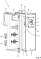
Fig. 4 shows the at least onedisplay element 18 and anacoustic element 19, for example a speaker, by which, in particular, a filling level of thereservoir 10, which is captured by alevel sensor 20 in thereservoir 10, and a battery charging level of thebattery 15 may be displayed or shown. Thedisplay element 18 may be configured more or less as a light bulb or a LED and/or also as a battery level indicator. -
Fig. 4 further shows another schematic side view of thehousing 2. The possibility of aninterchangeable panel 21 which is part of the faceplate and could be fixed to theholder 17, wherein thepanel 21 defines the diameter of theopening 7 of thefaceplate 3. Thepanel 21 may built theguidance element 8, and is adaptable to a diameter of the hose which should be lubricated. - What is not shown in the figures are hoses (to be distinguished from the hoses to be lubricated) or pipes for connecting the
reservoir 10 withsupply connections 11 and thenozzles 5. Because of the modular setup of thelubricating device 1 these connecting pipes may easily be provided and adaptions may be easily made. All pipes need to connect the at least onenozzle 5 with thesupply connections 11 and/or the tank may be hidden inside thehousing 2. - The
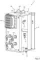
connectors 23 may send data to the BVIS and/or receive data from the BVIS. Thelubricating device 1 or spray unit is shown inFig. 5 from a schematic back view where the placement of theconnectors 23 is shown. - With the spray unit or
lubricating device 1 shown in the figures a method for lubricating hoses could be provided. Within the method a hose is inserted into the dispensingarea 6 through theopenings 7 of the faceplate and wherein the positioning is performed viaguidance element 8 and upon insertion thepump unit 9 is activated to dispense or spray the lubricant via the at least onenozzle 5. - Instead of the
frame 13 the sprayer box orhousing 2 of the lubricating machine orlubricating device 1 may be used as stand-alone unit or together with a custom container. - With the
lubricating device 1 and the method provided it is easily possible to lubricate a variety and multiple numbers of hoses in a constant and advantageous manner. -
- 1
- lubricating device
- 2
- housing
- 3
- faceplate
- 4
- wall
- 5
- nozzle
- 6
- dispensing area
- 7
- opening
- 8
- guidance element
- 9
- pump unit
- 10
- reservoir
- 11
- supply connection
- 12
- partial region
- 13
- frame
- 14
- mounting
- 15
- battery
- 16
- spray area
- 17
- holder
- 18
- display element
- 19
- acoustic element
- 20
- level sensor
- 21
- panel
- 22
- control unit
- 23
- electronic connectors
- 24
- switch
Claims (11)
- Lubricating device (1) for applying lubricant to a hose, comprising a housing (2) with a faceplate (3) and a wall (4), at least one nozzle (5) being arranged between these two, through which nozzle (5) lubricant is dispensable into a dispensing area (6), and the faceplate (3) having an opening (7), through which the hose is insertable into the dispensing area (6), wherein the hose is positionable via a guidance element (8) during insertion into the dispensing area (6) for application, and with a pump unit (9) which is designed to convey the lubricant from a reservoir (10) via the at least one nozzle (5) into the dispensing area (6).
- Lubricating device (1) according to claim 1,characterized in thatthe guidance element (8) and/or at least a partial region (12) of the wall (4) are designed to be pressure-sensitive so that the pump unit (9) is capable of being activated when pressure is applied to the guidance element (8) and/or the partial region (12).
- Lubricating device (1) according to claim 1 or 2,characterized in thatthe at least one nozzle (5) is arranged and/or has a shape such that the dispensing area (6) is formed such that lubricant is applicable to an inside and/or an outside of the positioned hose.
- Lubricating device (1) according to any one of the preceding claims,characterized in thatat least two nozzles (5) are present and the delivery of the lubricant at the at least two nozzles (5) is controllable via a switch so that the at least one first nozzle (5) of the at least two nozzles (5) defines the dispensing area for application to the inside of the hose and the at least one second nozzle (5) of the at least two nozzles (5) defines a second dispensing (6) area for application to the outside of the hose.
- Lubricating device (1) according to any one of the preceding claims,characterized in thata battery (15) is provided, for providing power to the pump unit (9), and the battery (15) is arranged on or in the housing.
- Lubricating device (1) according to any one of the preceding claims,characterized in thatat least one display element (18) and/or one acoustic element (19) are present, by means of which, in particular, a filling level of the reservoir (filling level sensor) and/or a battery level are outputable.
- Lubricating device (1) according to any one of the preceding claims,characterized in thatthe housing (2) is mounted on a frame (13) which has a mounting (14) for the reservoir (10).
- Lubricating device (1) according to claim 6,characterized in thatthe mounting (14) for the reservoir (10) is displaceably arranged so that the reservoir (10) is capable of being displaced between a pumping position and a removal position.
- Lubricating device (1) according to any one of the preceding claims,characterized in thatthe faceplate (3) or at least a panel (21) of the faceplate (3) comprising the opening (7) is capable of being exchanged so that a diameter of the opening (7) is adaptable to a diameter of the hose, and/or the frame (13) is designed to be adjustable in height.
- Lubricating device (1) according to any one of the preceding claims,characterized in thatan interface for data exchange with an external control device is provided.
- A method for applying lubricant to a hose with a lubricating device (1), comprising a housing (2) with a faceplate (3) and a wall (4), and at least one nozzle (5) disposed between the faceplate (3) and the wall (4), through which lubricant is dispensed into a dispensing area (6) when the hose is inserted into the dispensing area through an opening (7) in the faceplate (3), wherein the hose is positioned via a guidance element (8) upon insertion into the dispensing area (6), and a pump unit (9) delivers the lubricant from a reservoir (10) via the at least one nozzle (5) into the dispensing area.
Priority Applications (1)
| Application Number | Priority Date | Filing Date | Title |
|---|---|---|---|
| EP23190743.7A EP4506610B1 (en) | 2023-08-10 | 2023-08-10 | Lubricating device and a method for applying lubricant |
Applications Claiming Priority (1)
| Application Number | Priority Date | Filing Date | Title |
|---|---|---|---|
| EP23190743.7A EP4506610B1 (en) | 2023-08-10 | 2023-08-10 | Lubricating device and a method for applying lubricant |
Publications (2)
| Publication Number | Publication Date |
|---|---|
| EP4506610A1 true EP4506610A1 (en) | 2025-02-12 |
| EP4506610B1 EP4506610B1 (en) | 2026-02-18 |
Family
ID=87571309
Family Applications (1)
| Application Number | Title | Priority Date | Filing Date |
|---|---|---|---|
| EP23190743.7A Active EP4506610B1 (en) | 2023-08-10 | 2023-08-10 | Lubricating device and a method for applying lubricant |
Country Status (1)
| Country | Link |
|---|---|
| EP (1) | EP4506610B1 (en) |
Citations (5)
| Publication number | Priority date | Publication date | Assignee | Title |
|---|---|---|---|---|
| US3783972A (en) * | 1971-12-16 | 1974-01-08 | D Molstad | Wire lubricating device |
| US5632356A (en) * | 1995-08-28 | 1997-05-27 | Sells; Dan W. | Cable lubricating device and method |
| CN210890525U (en) * | 2019-11-29 | 2020-06-30 | 洛阳轻捷润滑油科技有限公司 | Special hose sealing connection device for lubricating oil |
| CN212052085U (en) * | 2020-03-11 | 2020-12-01 | 河南伯爵液压科技发展有限公司 | Steel wire stranding equipment for hydraulic rubber hose production |
| CN217684339U (en) * | 2022-07-23 | 2022-10-28 | 江苏神力医用制品有限公司 | Automatic assembling and lubricating equipment for medical hose |
-
2023
- 2023-08-10 EP EP23190743.7A patent/EP4506610B1/en active Active
Patent Citations (5)
| Publication number | Priority date | Publication date | Assignee | Title |
|---|---|---|---|---|
| US3783972A (en) * | 1971-12-16 | 1974-01-08 | D Molstad | Wire lubricating device |
| US5632356A (en) * | 1995-08-28 | 1997-05-27 | Sells; Dan W. | Cable lubricating device and method |
| CN210890525U (en) * | 2019-11-29 | 2020-06-30 | 洛阳轻捷润滑油科技有限公司 | Special hose sealing connection device for lubricating oil |
| CN212052085U (en) * | 2020-03-11 | 2020-12-01 | 河南伯爵液压科技发展有限公司 | Steel wire stranding equipment for hydraulic rubber hose production |
| CN217684339U (en) * | 2022-07-23 | 2022-10-28 | 江苏神力医用制品有限公司 | Automatic assembling and lubricating equipment for medical hose |
Also Published As
| Publication number | Publication date |
|---|---|
| EP4506610B1 (en) | 2026-02-18 |
Similar Documents
| Publication | Publication Date | Title |
|---|---|---|
| US5535849A (en) | Hand held transmission fluid changer | |
| CN1757964B (en) | Automatic lubricating device | |
| EP0651143B1 (en) | Apparatus for servicing automatic transmissions | |
| US7059450B2 (en) | Automatic lubrication system | |
| US20130251561A1 (en) | Fluid Pump System | |
| EP4506610B1 (en) | Lubricating device and a method for applying lubricant | |
| CN114950767B (en) | A backflow prevention atomizing nozzle and aroma diffuser | |
| ES2339010T3 (en) | AUTONOMOUS LUBRICANT DISPENSER. | |
| US8424722B2 (en) | Self contained lubricant dispenser | |
| US11992164B2 (en) | Counter mount foam dispenser | |
| JP2018052570A (en) | Fuel supply system | |
| CN103298731A (en) | Vapour recovery pump | |
| US5415324A (en) | Lubricant dispenser | |
| CN108584857B (en) | Glue supply device | |
| CA2635788C (en) | Automatic viscid substance actuator, dispenser and distributor | |
| CN103169409A (en) | Soap replenishment type soap supply device | |
| EP1463617A1 (en) | Apparatus and method for delivering fluent colourant material | |
| KR101893668B1 (en) | Automatic cleaner for automobile's air conditioner | |
| US11046175B2 (en) | Fueling system | |
| CN221208527U (en) | Spray gun base | |
| CN219906983U (en) | Suspension type oiling machine | |
| KR200298712Y1 (en) | automatic supplying lubricant system | |
| JP3353763B2 (en) | Refueling device | |
| US20210345837A1 (en) | Hand sanitizing station | |
| KR100358869B1 (en) | A pumping apparatus including a quick connect interface |
Legal Events
| Date | Code | Title | Description |
|---|---|---|---|
| PUAI | Public reference made under article 153(3) epc to a published international application that has entered the european phase |
Free format text: ORIGINAL CODE: 0009012 |
|
| STAA | Information on the status of an ep patent application or granted ep patent |
Free format text: STATUS: THE APPLICATION HAS BEEN PUBLISHED |
|
| AK | Designated contracting states |
Kind code of ref document: A1 Designated state(s): AL AT BE BG CH CY CZ DE DK EE ES FI FR GB GR HR HU IE IS IT LI LT LU LV MC ME MK MT NL NO PL PT RO RS SE SI SK SM TR |
|
| STAA | Information on the status of an ep patent application or granted ep patent |
Free format text: STATUS: REQUEST FOR EXAMINATION WAS MADE |
|
| 17P | Request for examination filed |
Effective date: 20250423 |
|
| GRAP | Despatch of communication of intention to grant a patent |
Free format text: ORIGINAL CODE: EPIDOSNIGR1 |
|
| STAA | Information on the status of an ep patent application or granted ep patent |
Free format text: STATUS: GRANT OF PATENT IS INTENDED |
|
| GRAS | Grant fee paid |
Free format text: ORIGINAL CODE: EPIDOSNIGR3 |
|
| RIC1 | Information provided on ipc code assigned before grant |
Ipc: F16N 7/38 20060101AFI20251205BHEP Ipc: F16N 21/00 20060101ALI20251205BHEP Ipc: F16L 57/06 20060101ALI20251205BHEP |
|
| GRAA | (expected) grant |
Free format text: ORIGINAL CODE: 0009210 |
|
| STAA | Information on the status of an ep patent application or granted ep patent |
Free format text: STATUS: THE PATENT HAS BEEN GRANTED |
|
| INTG | Intention to grant announced |
Effective date: 20251217 |
|
| AK | Designated contracting states |
Kind code of ref document: B1 Designated state(s): AL AT BE BG CH CY CZ DE DK EE ES FI FR GB GR HR HU IE IS IT LI LT LU LV MC ME MK MT NL NO PL PT RO RS SE SI SK SM TR |
|
| REG | Reference to a national code |
Ref country code: CH Ref legal event code: F10 Free format text: ST27 STATUS EVENT CODE: U-0-0-F10-F00 (AS PROVIDED BY THE NATIONAL OFFICE) Effective date: 20260218 Ref country code: GB Ref legal event code: FG4D |
|
| REG | Reference to a national code |
Ref country code: DE Ref legal event code: R096 Ref document number: 602023012112 Country of ref document: DE |
|
| REG | Reference to a national code |
Ref country code: IE Ref legal event code: FG4D |
|
| REG | Reference to a national code |
Ref country code: NL Ref legal event code: MP Effective date: 20260218 |
|
| PG25 | Lapsed in a contracting state [announced via postgrant information from national office to epo] |
Ref country code: RS Free format text: LAPSE BECAUSE OF FAILURE TO SUBMIT A TRANSLATION OF THE DESCRIPTION OR TO PAY THE FEE WITHIN THE PRESCRIBED TIME-LIMIT Effective date: 20260518 |
|
| PG25 | Lapsed in a contracting state [announced via postgrant information from national office to epo] |
Ref country code: ES Free format text: LAPSE BECAUSE OF FAILURE TO SUBMIT A TRANSLATION OF THE DESCRIPTION OR TO PAY THE FEE WITHIN THE PRESCRIBED TIME-LIMIT Effective date: 20260218 |
|
| PG25 | Lapsed in a contracting state [announced via postgrant information from national office to epo] |
Ref country code: PL Free format text: LAPSE BECAUSE OF FAILURE TO SUBMIT A TRANSLATION OF THE DESCRIPTION OR TO PAY THE FEE WITHIN THE PRESCRIBED TIME-LIMIT Effective date: 20260218 |
|
| PG25 | Lapsed in a contracting state [announced via postgrant information from national office to epo] |
Ref country code: GR Free format text: LAPSE BECAUSE OF FAILURE TO SUBMIT A TRANSLATION OF THE DESCRIPTION OR TO PAY THE FEE WITHIN THE PRESCRIBED TIME-LIMIT Effective date: 20260519 |
|
| REG | Reference to a national code |
Ref country code: LT Ref legal event code: MG9D |
|
| PG25 | Lapsed in a contracting state [announced via postgrant information from national office to epo] |
Ref country code: LT Free format text: LAPSE BECAUSE OF FAILURE TO SUBMIT A TRANSLATION OF THE DESCRIPTION OR TO PAY THE FEE WITHIN THE PRESCRIBED TIME-LIMIT Effective date: 20260218 |
|
| PG25 | Lapsed in a contracting state [announced via postgrant information from national office to epo] |
Ref country code: NO Free format text: LAPSE BECAUSE OF FAILURE TO SUBMIT A TRANSLATION OF THE DESCRIPTION OR TO PAY THE FEE WITHIN THE PRESCRIBED TIME-LIMIT Effective date: 20260518 |
|
| PG25 | Lapsed in a contracting state [announced via postgrant information from national office to epo] |
Ref country code: SE Free format text: LAPSE BECAUSE OF FAILURE TO SUBMIT A TRANSLATION OF THE DESCRIPTION OR TO PAY THE FEE WITHIN THE PRESCRIBED TIME-LIMIT Effective date: 20260218 Ref country code: FI Free format text: LAPSE BECAUSE OF FAILURE TO SUBMIT A TRANSLATION OF THE DESCRIPTION OR TO PAY THE FEE WITHIN THE PRESCRIBED TIME-LIMIT Effective date: 20260218 Ref country code: AT Free format text: LAPSE BECAUSE OF FAILURE TO SUBMIT A TRANSLATION OF THE DESCRIPTION OR TO PAY THE FEE WITHIN THE PRESCRIBED TIME-LIMIT Effective date: 20260218 |
|
| REG | Reference to a national code |
Ref country code: AT Ref legal event code: MK05 Ref document number: 1888352 Country of ref document: AT Kind code of ref document: T Effective date: 20260218 |
|
| PG25 | Lapsed in a contracting state [announced via postgrant information from national office to epo] |
Ref country code: HR Free format text: LAPSE BECAUSE OF FAILURE TO SUBMIT A TRANSLATION OF THE DESCRIPTION OR TO PAY THE FEE WITHIN THE PRESCRIBED TIME-LIMIT Effective date: 20260218 |
|
| PG25 | Lapsed in a contracting state [announced via postgrant information from national office to epo] |
Ref country code: IS Free format text: LAPSE BECAUSE OF FAILURE TO SUBMIT A TRANSLATION OF THE DESCRIPTION OR TO PAY THE FEE WITHIN THE PRESCRIBED TIME-LIMIT Effective date: 20260618 Ref country code: PT Free format text: LAPSE BECAUSE OF FAILURE TO SUBMIT A TRANSLATION OF THE DESCRIPTION OR TO PAY THE FEE WITHIN THE PRESCRIBED TIME-LIMIT Effective date: 20260618 |
|
| PG25 | Lapsed in a contracting state [announced via postgrant information from national office to epo] |
Ref country code: NL Free format text: LAPSE BECAUSE OF FAILURE TO SUBMIT A TRANSLATION OF THE DESCRIPTION OR TO PAY THE FEE WITHIN THE PRESCRIBED TIME-LIMIT Effective date: 20260218 |
|
| PG25 | Lapsed in a contracting state [announced via postgrant information from national office to epo] |
Ref country code: LV Free format text: LAPSE BECAUSE OF FAILURE TO SUBMIT A TRANSLATION OF THE DESCRIPTION OR TO PAY THE FEE WITHIN THE PRESCRIBED TIME-LIMIT Effective date: 20260218 |
|
| PG25 | Lapsed in a contracting state [announced via postgrant information from national office to epo] |
Ref country code: BG Free format text: LAPSE BECAUSE OF FAILURE TO SUBMIT A TRANSLATION OF THE DESCRIPTION OR TO PAY THE FEE WITHIN THE PRESCRIBED TIME-LIMIT Effective date: 20260218 |