EP4506599A1 - Valve and valve assembly method - Google Patents
Valve and valve assembly method Download PDFInfo
- Publication number
- EP4506599A1 EP4506599A1 EP23784676.1A EP23784676A EP4506599A1 EP 4506599 A1 EP4506599 A1 EP 4506599A1 EP 23784676 A EP23784676 A EP 23784676A EP 4506599 A1 EP4506599 A1 EP 4506599A1
- Authority
- EP
- European Patent Office
- Prior art keywords
- casing
- retainer
- valve
- flange portion
- wave washer
- Prior art date
- Legal status (The legal status is an assumption and is not a legal conclusion. Google has not performed a legal analysis and makes no representation as to the accuracy of the status listed.)
- Pending
Links
Images


Classifications
-
- F—MECHANICAL ENGINEERING; LIGHTING; HEATING; WEAPONS; BLASTING
- F16—ENGINEERING ELEMENTS AND UNITS; GENERAL MEASURES FOR PRODUCING AND MAINTAINING EFFECTIVE FUNCTIONING OF MACHINES OR INSTALLATIONS; THERMAL INSULATION IN GENERAL
- F16K—VALVES; TAPS; COCKS; ACTUATING-FLOATS; DEVICES FOR VENTING OR AERATING
- F16K27/00—Construction of housing; Use of materials therefor
- F16K27/04—Construction of housing; Use of materials therefor of sliding valves
- F16K27/041—Construction of housing; Use of materials therefor of sliding valves cylindrical slide valves
-
- F—MECHANICAL ENGINEERING; LIGHTING; HEATING; WEAPONS; BLASTING
- F16—ENGINEERING ELEMENTS AND UNITS; GENERAL MEASURES FOR PRODUCING AND MAINTAINING EFFECTIVE FUNCTIONING OF MACHINES OR INSTALLATIONS; THERMAL INSULATION IN GENERAL
- F16K—VALVES; TAPS; COCKS; ACTUATING-FLOATS; DEVICES FOR VENTING OR AERATING
- F16K11/00—Multiple-way valves, e.g. mixing valves; Pipe fittings incorporating such valves
- F16K11/02—Multiple-way valves, e.g. mixing valves; Pipe fittings incorporating such valves with all movable sealing faces moving as one unit
- F16K11/06—Multiple-way valves, e.g. mixing valves; Pipe fittings incorporating such valves with all movable sealing faces moving as one unit comprising only sliding valves, i.e. sliding closure elements
- F16K11/065—Multiple-way valves, e.g. mixing valves; Pipe fittings incorporating such valves with all movable sealing faces moving as one unit comprising only sliding valves, i.e. sliding closure elements with linearly sliding closure members
- F16K11/07—Multiple-way valves, e.g. mixing valves; Pipe fittings incorporating such valves with all movable sealing faces moving as one unit comprising only sliding valves, i.e. sliding closure elements with linearly sliding closure members with cylindrical slides
-
- F—MECHANICAL ENGINEERING; LIGHTING; HEATING; WEAPONS; BLASTING
- F16—ENGINEERING ELEMENTS AND UNITS; GENERAL MEASURES FOR PRODUCING AND MAINTAINING EFFECTIVE FUNCTIONING OF MACHINES OR INSTALLATIONS; THERMAL INSULATION IN GENERAL
- F16K—VALVES; TAPS; COCKS; ACTUATING-FLOATS; DEVICES FOR VENTING OR AERATING
- F16K27/00—Construction of housing; Use of materials therefor
- F16K27/04—Construction of housing; Use of materials therefor of sliding valves
- F16K27/048—Electromagnetically actuated valves
-
- F—MECHANICAL ENGINEERING; LIGHTING; HEATING; WEAPONS; BLASTING
- F16—ENGINEERING ELEMENTS AND UNITS; GENERAL MEASURES FOR PRODUCING AND MAINTAINING EFFECTIVE FUNCTIONING OF MACHINES OR INSTALLATIONS; THERMAL INSULATION IN GENERAL
- F16K—VALVES; TAPS; COCKS; ACTUATING-FLOATS; DEVICES FOR VENTING OR AERATING
- F16K2200/00—Details of valves
- F16K2200/30—Spring arrangements
- F16K2200/305—Constructional features of springs
- F16K2200/3051—Generally flat springs
-
- F—MECHANICAL ENGINEERING; LIGHTING; HEATING; WEAPONS; BLASTING
- F16—ENGINEERING ELEMENTS AND UNITS; GENERAL MEASURES FOR PRODUCING AND MAINTAINING EFFECTIVE FUNCTIONING OF MACHINES OR INSTALLATIONS; THERMAL INSULATION IN GENERAL
- F16K—VALVES; TAPS; COCKS; ACTUATING-FLOATS; DEVICES FOR VENTING OR AERATING
- F16K31/00—Actuating devices; Operating means; Releasing devices
- F16K31/02—Actuating devices; Operating means; Releasing devices electric; magnetic
- F16K31/06—Actuating devices; Operating means; Releasing devices electric; magnetic using a magnet, e.g. diaphragm valves, cutting off by means of a liquid
- F16K31/0603—Multiple-way valves
- F16K31/061—Sliding valves
- F16K31/0613—Sliding valves with cylindrical slides
-
- Y—GENERAL TAGGING OF NEW TECHNOLOGICAL DEVELOPMENTS; GENERAL TAGGING OF CROSS-SECTIONAL TECHNOLOGIES SPANNING OVER SEVERAL SECTIONS OF THE IPC; TECHNICAL SUBJECTS COVERED BY FORMER USPC CROSS-REFERENCE ART COLLECTIONS [XRACs] AND DIGESTS
- Y10—TECHNICAL SUBJECTS COVERED BY FORMER USPC
- Y10T—TECHNICAL SUBJECTS COVERED BY FORMER US CLASSIFICATION
- Y10T137/00—Fluid handling
- Y10T137/8593—Systems
- Y10T137/86493—Multi-way valve unit
- Y10T137/86574—Supply and exhaust
- Y10T137/86582—Pilot-actuated
- Y10T137/86614—Electric
-
- Y—GENERAL TAGGING OF NEW TECHNOLOGICAL DEVELOPMENTS; GENERAL TAGGING OF CROSS-SECTIONAL TECHNOLOGIES SPANNING OVER SEVERAL SECTIONS OF THE IPC; TECHNICAL SUBJECTS COVERED BY FORMER USPC CROSS-REFERENCE ART COLLECTIONS [XRACs] AND DIGESTS
- Y10—TECHNICAL SUBJECTS COVERED BY FORMER USPC
- Y10T—TECHNICAL SUBJECTS COVERED BY FORMER US CLASSIFICATION
- Y10T137/00—Fluid handling
- Y10T137/8593—Systems
- Y10T137/86493—Multi-way valve unit
- Y10T137/86574—Supply and exhaust
- Y10T137/86622—Motor-operated
-
- Y—GENERAL TAGGING OF NEW TECHNOLOGICAL DEVELOPMENTS; GENERAL TAGGING OF CROSS-SECTIONAL TECHNOLOGIES SPANNING OVER SEVERAL SECTIONS OF THE IPC; TECHNICAL SUBJECTS COVERED BY FORMER USPC CROSS-REFERENCE ART COLLECTIONS [XRACs] AND DIGESTS
- Y10—TECHNICAL SUBJECTS COVERED BY FORMER USPC
- Y10T—TECHNICAL SUBJECTS COVERED BY FORMER US CLASSIFICATION
- Y10T137/00—Fluid handling
- Y10T137/8593—Systems
- Y10T137/87169—Supply and exhaust
- Y10T137/87193—Pilot-actuated
- Y10T137/87209—Electric
-
- Y—GENERAL TAGGING OF NEW TECHNOLOGICAL DEVELOPMENTS; GENERAL TAGGING OF CROSS-SECTIONAL TECHNOLOGIES SPANNING OVER SEVERAL SECTIONS OF THE IPC; TECHNICAL SUBJECTS COVERED BY FORMER USPC CROSS-REFERENCE ART COLLECTIONS [XRACs] AND DIGESTS
- Y10—TECHNICAL SUBJECTS COVERED BY FORMER USPC
- Y10T—TECHNICAL SUBJECTS COVERED BY FORMER US CLASSIFICATION
- Y10T137/00—Fluid handling
- Y10T137/8593—Systems
- Y10T137/87169—Supply and exhaust
- Y10T137/87217—Motor
Definitions
- the present invention relates to a valve and a valve assembly method, for example, a valve for controlling a hydraulic fluid and a method of assembling the valve.
- a valve that is used to control a hydraulic fluid in various industrial fields includes a valve seat and a valve body movable close to and away from the valve seat and can control the pressure or flow rate of the hydraulic fluid by adjusting a valve opening degree.
- a spool valve in which a spool corresponding to a valve body moves in parallel to an opening corresponding to a valve seat, a butterfly valve of which a valve body has a rotation axis, or a lift valve of which a valve body moves perpendicular to an opening corresponding to a valve seat is typically exemplified.
- the spool valve has high spool responsiveness to a driving force since a spool movement direction intersects a hydraulic fluid flow direction and a fluid pressure of a hydraulic fluid is less likely to act in the spool movement direction.
- a solenoid valve of Patent Citation 1 As the spool valve, for example, a solenoid valve of Patent Citation 1 is known.
- the solenoid valve of Patent Citation 1 mainly includes a columnar spool which is accommodated in a sleeve, a solenoid portion which is fixed to one end of the sleeve and drives the spool, a retainer which is fixed to the other end of the sleeve, and a biasing means which is held between the spool and the retainer.
- the retainer has a cylindrical shape with a bottom that opens on the sleeve side, and a flange extending radially outward is formed at a sleeve side end. Further, a caulking piece extending from an end surface of the sleeve toward the retainer is formed around the entire circumference on the outer edge of the end of the sleeve on the retainer side.
- Patent Citation 1 WO 2010/024282 A (PAGE 7, FIG. 2B)
- the present invention has been made in view of such problems and an object of the present invention is to provide a valve and a method of assembling the valve that can maintain a stable fixed state between a retainer and a casing for a long period of time.
- a valve including: a casing; a valve body that is operable inside the casing; a biasing member that biases the valve body; and a retainer that holds the biasing member, wherein the retainer is provided with a flange portion caulked and fixed to the casing by a caulking end provided at one axial end of the casing, and wherein an elastic member is sandwiched between the flange portion and the casing to be axially elastically deformable.
- the flange portion and the caulking end are maintained in a contact state due to the elastic restoring force of the elastic member even when the caulking end is deformed due to aging and hence the casing and the retainer do not rattle.
- the elastic member is disposed between the flange portion and an end surface of the casing facing the caulking end. According to this preferable configuration, the elastic restoring force of the elastic member can stably act on the caulking end through the flange portion.
- a surface of the flange portion facing the end surface of the casing is an annular flat surface. According to this preferable configuration, the elastic member can be stably sandwiched between the end surface of the casing and the facing surface of the flange portion.
- the elastic member is formed in an annular shape. According to this preferable configuration, the elastic member is continuous in the circumferential direction without interruption and a strong elastic restoring force from the elastic member acts almost uniformly in the circumferential direction. Therefore, the relative inclination between the retainer and the casing can be suppressed.
- the elastic member is a wave washer. According to this preferable configuration, since the wave washer comes into contact with the casing at a plurality of positions in the circumferential direction, the elastic restoring force can suitably act substantially uniformly in the circumferential direction of the retainer. Therefore, the relative inclination of the retainer and the casing can be further suppressed.
- an inner peripheral surface of the caulking end is provided with a regulation surface that regulates the radial movement of the flange portion. According to this preferable configuration, the inclination and radial deviation of the retainer can be regulated.
- a method of assembling a valve including a casing, a valve body operable inside the casing, a biasing member that biases the valve body, and a retainer that holds the biasing member, wherein the retainer is provide with a flange portion caulked and fixed to the casing by a caulking end provided at one axial end of the casing, and the method comprises a step of locking the caulking end to the flange portion while an elastic member disposed between the flange portion and the casing is axially compressed.
- the flange portion and the caulking end are maintained in a contact state due to the elastic restoring force of the elastic member even when the caulking end is deformed due to aging and hence the casing and the retainer do not rattle.
- a mode for carrying out a valve according to the present invention will be described on the basis of the embodiment. Furthermore, although the embodiment will be described by using a solenoid valve as an example, it is also applicable to other uses.
- FIGS. 1 to 5 A solenoid valve as a valve according to an embodiment of the present invention will be described with reference to FIGS. 1 to 5 .
- a description will be made assuming that the right side of the paper of FIG. 1 is one axial end side of the solenoid valve and the left side of the paper of FIG. 1 is the other axial end side of the solenoid valve.
- a solenoid valve 1 of this embodiment is a spool type solenoid valve, and is used in a device controlled by hydraulic pressure, such as an automatic transmission of a vehicle. Furthermore, the solenoid valve 1 is used by being attached to a mounting hole in a valve housing on the device side.
- the solenoid valve 1 includes a valve portion 2 that adjusts the flow rate of fluid, that is, a control fluid such as hydraulic oil, and is integrally attached to a solenoid portion 3. Furthermore, FIG. 1 illustrates the solenoid valve 1 in an off state in which the coil of the solenoid portion 3 is not energized.
- the structure of the solenoid portion 3 will be schematically described.
- a coil, a stator, a yoke, a movable core, and the like are accommodated in a cylindrical solenoid casing 30.
- a spool 22 is biased toward the other axial end by a biasing force of a spring 29 (see FIG. 1 .) and the spool 22 and a rod 5 move toward the other axial end in accordance with this biasing.
- a magnetic circuit is formed in the solenoid portion 3 by energizing the coil and a magnetic force is generated between the stator and the movable core, so that the movable core and the rod 5 move toward one axial end in the axial direction. Accordingly, the spool 22 moves toward one axial end to compress the spring 29 (not illustrated).
- the valve portion 2 mainly includes a sleeve 21 which serves as a casing, a spool 22 which serves as a valve body, a spring 29 which serves as a biasing member, a retainer 23, and a wave washer 200 which serves as an elastic member.
- the sleeve 21 is provided with openings for various ports such as an input port 24, an output port 25, a discharge port 26, a drain port 27, and a feedback port 28, which are connected to the flow path provided in the mounting hole of the valve housing.
- the spool 22 is fluid-tightly accommodated in a through hole 21a formed in the axial direction on the inner radial side of the sleeve 21.
- the spool 22 is capable of reciprocating in the axial direction, and when the spool 22 is reciprocated in the axial direction, the communication state of various ports is changed, and the pressure and flow rate of the hydraulic oil are controlled. Furthermore, the sleeve 21 and the spool 22 are made of materials such as aluminum, iron, stainless steel, and resin.
- the spring 29 is a coil spring, and biases the spool 22 toward the other axial end. Further, one axial end of the spring 29 is held by the retainer 23.
- the retainer 23 has a cylindrical shape with a bottom.
- the retainer 23 includes a disc-shaped bottom portion 23a which serves as a seat surface, a cylindrical side wall portion 23b which serves as a cylindrical portion extending from the outer edge of the bottom portion 23a toward the other axial end, and an annular flange portion 23d which extends radially outward from the other axial end of the side wall portion 23b.
- the retainer 23 is formed by pressing a thin plate made of a plastically deformable material such as aluminum, iron, or stainless steel, preferably a metal.
- One through-hole 23e is provided at the center of the bottom portion 23a.
- the side wall portion 23b extends from the outer edge of the bottom portion 23a toward the other axial end while being slightly expanded in diameter.
- the flange portion 23d is bent radially outward from the other axial end of the side wall portion 23b and extends substantially in parallel to the bottom portion 23a.
- the retainer 23 configured in this way is fixed to the sleeve 21 by caulking a caulking piece 21c serving as a caulking end extending from an outer edge of an end surface 21b toward one axial end side to the inner radial side while disposing the flange portion 23d on the end surface 21b on one axial end side of the sleeve 21 through the wave washer 200 (see FIG. 2 ).
- a wave washer 200'' is a thin annular metal plate that is bent in a wave shape in the circumferential direction to apply a spring force. Since this wave washer 200'' has four peaks and valleys in the circumferential direction, the wave washer can receive an axial load uniformly in the circumferential direction. Furthermore, FIG. 3 illustrates the wave washer 200'' in a natural state without being compressed. Furthermore, the number of peaks and valleys of the wave washer 200'' may be freely changed.
- the spring constant of the wave washer 200'' of this embodiment is larger than the spring constant of the spring 29.
- the wave washer 200'' and the retainer 23 are arranged at one axial end of the sleeve 21. At this time, the wave washer 200'' is disposed to be sandwiched between the end surface 21b of the sleeve 21 and the other end surface 23h of the flange portion 23d of the retainer 23 (see FIG. 4B .).
- the retainer 23 and the wave washer 200'' are temporarily fixed to the sleeve 21 by bending the caulking piece 21c, extending from the outer edge of the end surface 21b of the sleeve 21 toward one axial end side, toward the inner radial side.
- a plurality of the caulking pieces 21c are provided in the circumferential direction. Specifically, since the outer edge of the end surface 21b is provided in an arc shape except for a part in the circumferential direction, the bending stress can be released to the part divided in the circumferential direction when bending the caulking piece 21c radially inward. Furthermore, the caulking piece 21c may have one annular shape in the circumferential direction or may have one C-shape in the circumferential direction.
- the wave washer 200'' can be stably sandwiched between the other end surface 23h of the flange portion 23d and the end surface 21b of the sleeve 21.
- the inner peripheral surface 21e of the portion on the other axial end side than the bent portion of each caulking piece 21c regulates the radial movement and inclination of the flange portion 23d and the wave washer 200'' and allows the axial movement thereof. That is, the inner peripheral surface 21e of the caulking piece 21c functions as a regulation surface that regulates the movement of the flange portion 23d in the radial direction.
- the caulking piece 21c comes into contact with only the outer edge of flange portion 23d of the retainer 23 and almost no force is applied to press the flange portion 23d toward the other axial end side.
- the wave washer 200" is in a natural state without compressing.
- the solenoid portion 3 is fixed to the other axial end of the sleeve 21 (that is, the state illustrated in FIG. 4C .).
- the spring 29 passes through the wave washer 200'' and one axial end of the spring 29 is adapted to abut and be received by the bottom portion 23a of the retainer 23.
- the axial dimension between the end surface 21b of the sleeve 21 and the other end surface of the bottom portion 23a of the retainer 23 is L1.
- the caulking piece 21c is pressed toward the other axial end by a jig (not illustrated) to adjust the biasing force of the spring 29 (see black arrow). Furthermore, at this time, the biasing force of the spring 29 is adjusted while directly or indirectly monitoring the biasing force of the spring 29 using a sensor.
- the wave washer 200'' is compressed in the axial direction to be the wave washer 200' (200'' ⁇ 200'). Accordingly, the bottom portion 23a of the retainer 23 approaches the end surface 21b of the sleeve 21 in the axial direction.
- the axial dimension L2 between the end surface 21b of the sleeve 21 and the other end surface of the bottom portion 23a of the retainer 23 is shorter than the axial dimension L1 of FIG. 4C (L1 > L2).
- the caulking piece 21c is further pressed toward the other axial end side by a jig (not illustrated) so that the bottom portion 23a further approaches the end surface 21b of the sleeve 21 in the axial direction.
- the axial dimension L3 between the end surface 21b of the sleeve 21 and the other end surface of the bottom portion 23a of the retainer 23 is shorter than the axial dimension L2 of FIG. 5A (L2 > L3).
- the axial dimension L3 is a dimension in which the biasing force of the spring 29 is appropriate.
- the wave washer 200' is further compressed in the axial direction to be the wave washer 200 (200' ⁇ 200).
- the wave washer 200 tries to be elastically restored, but since the wave washer 200 is locked to the plastically deformed caulking piece 21c, the wave washer 200 remains compressed in the axial direction. That is, an elastic restoring force (see white arrow) of the wave washer 200 acts between the end surface 21b of the sleeve 21 and the caulking piece 21c.
- the through-hole 23e is provided in the bottom portion 23a of the retainer 23 and the through-hole 23e can be used as a breathing hole to allow hydraulic oil to flow, the spool 22 can be operated smoothly when the solenoid valve 1 is used.
- the biasing force of the spring 29 can be adjusted with high accuracy.
- the elastic restoring force of the wave washer 200 acts between the flange portion 23d of the retainer 23 and the end surface 21b of the sleeve 21, the flange portion 23d and the caulking piece 21c are maintained in a contact state due to the elastic restoring force of the wave washer 200 even when the caulking piece 21c is deformed, for example, in the opening direction due to aging and hence the sleeve 21 and the retainer 23 do not rattle.
- the retainer is also elastically restored, the restoring amount is extremely small compared to the elastic restoring amount of the wave washer and hence a description thereof will be omitted.
- the wave washer 200 is disposed between the flange portion 23d of the retainer 23 and the end surface 21b of the sleeve 21, the elastic restoring force of the wave washer 200 can be stably applied to the caulking piece 21c through the flange portion 23d.
- the wave washer 200 can be stably sandwiched between the other end surface 23h of the flange portion 23d and the end surface 21b of the sleeve 21.
- the wave washer 200 is formed in an annular shape.
- the wave washer 200 is continuous in the circumferential direction without interruption and a strong elastic restoring force from the wave washer 200 suitably acts over the entire circumference of the flange portion 23d.
- the elastic restoring force of the wave washer 200 can suitably act substantially uniformly in the circumferential direction of the retainer 23. Therefore, the relative inclination of the retainer 23 and the wave washer 200 can be suppressed.
- the plate thickness of the wave washer 200 is smaller than the caulking piece 21c and the flange portion 23d, the elastic restoring force of the wave washer 200 can be adjusted satisfactorily.
- the width corresponding to the radial length of the wave washer 200 is substantially the same as the radial length of the end surface 21b of the sleeve 21 and the flange portion 23d, the elastic restoring force of the wave washer 200 can be adjusted with a simple structure. Furthermore, although the width corresponding to the radial length of the wave washer 200 can be freely changed, the width is preferably 0.5 to 2 times the radial length of the end surface 21b of the sleeve 21 and the flange portion 23d.
- the inner peripheral surface 21e of the caulking piece 21c can regulate the inclination and radial deviation of the retainer 23 relative to the sleeve 21. Further, since the inner peripheral surface 21e allows the axial movement of the flange portion 23d, the retainer 23 can be stably moved in the axial direction and the biasing force of the spring 29 can be adjusted with high accuracy.
- the spring constant of the wave washer 200 disposed at a position overlapping the caulking piece 21c in the axial direction is larger than the spring constant of the spring 29 disposed at a position radially offset from the caulking piece 21c, the inclination of the retainer 23 can be regulated even when the spring 29 is slightly inclined.
- the elastic member is sandwiched between the flange portion of the retainer and the end surface of the casing
- the elastic member may be sandwiched between the flange portion and the caulking end.
- the casing and the retainer can be maintained in a fixed state due to the elastic restoring force of the elastic member.
- the elastic member has an annular shape
- the present invention is not limited thereto, and the elastic member that is axially elastically deformable may be provided at a plurality of positions in the circumferential direction.
- the elastic member is the metallic wave washer
- the elastic member may be made of rubber or synthetic resin.
- the elastic member is separated from the flange portion of the retainer and the casing, the elastic member may be fixed to the flange portion or the end surface of the casing.
- the retainer 23 is made of a plastically deformable metal thin plate
- the present invention is not limited thereto, and the material can be freely changed.
- the biasing member is a compression spring
- the biasing member may be a tension spring
- a spool type valve that uses a spool as a valve body
- the present invention is not limited thereto, and a globe valve, a gate valve, or the like may be used.
Landscapes
- Engineering & Computer Science (AREA)
- General Engineering & Computer Science (AREA)
- Mechanical Engineering (AREA)
- Physics & Mathematics (AREA)
- Electromagnetism (AREA)
- Magnetically Actuated Valves (AREA)
Abstract
Description
- The present invention relates to a valve and a valve assembly method, for example, a valve for controlling a hydraulic fluid and a method of assembling the valve.
- A valve that is used to control a hydraulic fluid in various industrial fields includes a valve seat and a valve body movable close to and away from the valve seat and can control the pressure or flow rate of the hydraulic fluid by adjusting a valve opening degree.
- As such a valve, a spool valve in which a spool corresponding to a valve body moves in parallel to an opening corresponding to a valve seat, a butterfly valve of which a valve body has a rotation axis, or a lift valve of which a valve body moves perpendicular to an opening corresponding to a valve seat is typically exemplified. Among these valves, the spool valve has high spool responsiveness to a driving force since a spool movement direction intersects a hydraulic fluid flow direction and a fluid pressure of a hydraulic fluid is less likely to act in the spool movement direction.
- As the spool valve, for example, a solenoid valve of Patent Citation 1 is known. The solenoid valve of Patent Citation 1 mainly includes a columnar spool which is accommodated in a sleeve, a solenoid portion which is fixed to one end of the sleeve and drives the spool, a retainer which is fixed to the other end of the sleeve, and a biasing means which is held between the spool and the retainer.
- The retainer has a cylindrical shape with a bottom that opens on the sleeve side, and a flange extending radially outward is formed at a sleeve side end. Further, a caulking piece extending from an end surface of the sleeve toward the retainer is formed around the entire circumference on the outer edge of the end of the sleeve on the retainer side. By bending the caulking piece radially inward while disposing the flange of the retainer on the inner radial side of the caulking piece, the flange is axially sandwiched between the caulking piece and the end surface of the sleeve and hence the retainer can be firmly fixed to the end of the sleeve.
- Patent Citation 1:
WO 2010/024282 A (PAGE 7, FIG. 2B) - In the solenoid valve of Patent Citation 1, since the flange is axially sandwiched between the caulking piece and the end surface of the sleeve with its surface in contact with the end surface of the sleeve, the retainer and the sleeve can be strongly and simply fixed. However, in such a solenoid valve, the caulking piece may be deformed due to aging. As a result, there is a risk that a gap may be formed between the caulking piece and the flange and rattling may occur between the retainer and the sleeve.
- The present invention has been made in view of such problems and an object of the present invention is to provide a valve and a method of assembling the valve that can maintain a stable fixed state between a retainer and a casing for a long period of time.
- In order to solve the foregoing problem, according to a first aspect of the present invention, there is provided a valve including: a casing; a valve body that is operable inside the casing; a biasing member that biases the valve body; and a retainer that holds the biasing member, wherein the retainer is provided with a flange portion caulked and fixed to the casing by a caulking end provided at one axial end of the casing, and wherein an elastic member is sandwiched between the flange portion and the casing to be axially elastically deformable. According to the aforesaid feature of the first aspect of the present invention, since the elastic member is sandwiched between the casing and the flange portion of the retainer, the flange portion and the caulking end are maintained in a contact state due to the elastic restoring force of the elastic member even when the caulking end is deformed due to aging and hence the casing and the retainer do not rattle.
- It may be preferable that the elastic member is disposed between the flange portion and an end surface of the casing facing the caulking end. According to this preferable configuration, the elastic restoring force of the elastic member can stably act on the caulking end through the flange portion.
- It may be preferable that a surface of the flange portion facing the end surface of the casing is an annular flat surface. According to this preferable configuration, the elastic member can be stably sandwiched between the end surface of the casing and the facing surface of the flange portion.
- It may be preferable that the elastic member is formed in an annular shape. According to this preferable configuration, the elastic member is continuous in the circumferential direction without interruption and a strong elastic restoring force from the elastic member acts almost uniformly in the circumferential direction. Therefore, the relative inclination between the retainer and the casing can be suppressed.
- It may be preferable that the elastic member is a wave washer. According to this preferable configuration, since the wave washer comes into contact with the casing at a plurality of positions in the circumferential direction, the elastic restoring force can suitably act substantially uniformly in the circumferential direction of the retainer. Therefore, the relative inclination of the retainer and the casing can be further suppressed.
- It may be preferable that an inner peripheral surface of the caulking end is provided with a regulation surface that regulates the radial movement of the flange portion. According to this preferable configuration, the inclination and radial deviation of the retainer can be regulated.
- According to a second aspect of the present invention, there is provided a method of assembling a valve including a casing, a valve body operable inside the casing, a biasing member that biases the valve body, and a retainer that holds the biasing member, wherein the retainer is provide with a flange portion caulked and fixed to the casing by a caulking end provided at one axial end of the casing, and the method comprises a step of locking the caulking end to the flange portion while an elastic member disposed between the flange portion and the casing is axially compressed. According to the features of second aspect of the present invention, since the elastic member is sandwiched between the casing and the flange portion of the retainer, the flange portion and the caulking end are maintained in a contact state due to the elastic restoring force of the elastic member even when the caulking end is deformed due to aging and hence the casing and the retainer do not rattle.
-
-
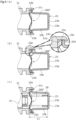
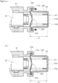
FIG. 1 is a side sectional view illustrating a solenoid valve as a valve according to an embodiment of the present invention. -
FIG. 2 is an enlarged view of a main part ofFIG. 1 . -
FIG. 3 is a perspective view illustrating a shape of a wave washer. -
FIG. 4A is a schematic view illustrating a state in which the wave washer and a retainer are arranged at one end of a sleeve,FIG. 4B is a schematic view illustrating a state in which the wave washer and the retainer are temporarily fixed to one end of the sleeve from the state ofFIG. 4A, and FIG. 4C is a schematic view illustrating a state in which a spring and a spool are assembled from the state ofFIG. 4B . -
FIG. 5A is a schematic view illustrating a state in which the spring is compressed from the state ofFIG. 4C andFIG. 5B is a schematic view illustrating a state in which the spring is further compressed from the state ofFIG. 5A . - A mode for carrying out a valve according to the present invention will be described on the basis of the embodiment. Furthermore, although the embodiment will be described by using a solenoid valve as an example, it is also applicable to other uses.
- A solenoid valve as a valve according to an embodiment of the present invention will be described with reference to
FIGS. 1 to 5 . Hereinafter, a description will be made assuming that the right side of the paper ofFIG. 1 is one axial end side of the solenoid valve and the left side of the paper ofFIG. 1 is the other axial end side of the solenoid valve. - As illustrated in
FIG. 1 , asolenoid valve 1 of this embodiment is a spool type solenoid valve, and is used in a device controlled by hydraulic pressure, such as an automatic transmission of a vehicle. Furthermore, thesolenoid valve 1 is used by being attached to a mounting hole in a valve housing on the device side. - The
solenoid valve 1 includes avalve portion 2 that adjusts the flow rate of fluid, that is, a control fluid such as hydraulic oil, and is integrally attached to asolenoid portion 3. Furthermore,FIG. 1 illustrates thesolenoid valve 1 in an off state in which the coil of thesolenoid portion 3 is not energized. - First, the structure of the
solenoid portion 3 will be schematically described. In thesolenoid portion 3, a coil, a stator, a yoke, a movable core, and the like are accommodated in acylindrical solenoid casing 30. When thesolenoid valve 1 is in an off state, aspool 22 is biased toward the other axial end by a biasing force of a spring 29 (seeFIG. 1 .) and thespool 22 and arod 5 move toward the other axial end in accordance with this biasing. - Further, when the
solenoid valve 1 is in an on state, a magnetic circuit is formed in thesolenoid portion 3 by energizing the coil and a magnetic force is generated between the stator and the movable core, so that the movable core and therod 5 move toward one axial end in the axial direction. Accordingly, thespool 22 moves toward one axial end to compress the spring 29 (not illustrated). - Next, the structure of the
valve portion 2 will be described. As illustrated inFIG. 1 , thevalve portion 2 mainly includes asleeve 21 which serves as a casing, aspool 22 which serves as a valve body, aspring 29 which serves as a biasing member, aretainer 23, and awave washer 200 which serves as an elastic member. - The
sleeve 21 is provided with openings for various ports such as aninput port 24, anoutput port 25, adischarge port 26, adrain port 27, and afeedback port 28, which are connected to the flow path provided in the mounting hole of the valve housing. - The
spool 22 is fluid-tightly accommodated in a throughhole 21a formed in the axial direction on the inner radial side of thesleeve 21. - The
spool 22 is capable of reciprocating in the axial direction, and when thespool 22 is reciprocated in the axial direction, the communication state of various ports is changed, and the pressure and flow rate of the hydraulic oil are controlled. Furthermore, thesleeve 21 and thespool 22 are made of materials such as aluminum, iron, stainless steel, and resin. - The
spring 29 is a coil spring, and biases thespool 22 toward the other axial end. Further, one axial end of thespring 29 is held by theretainer 23. - As illustrated in
FIG. 2 , theretainer 23 has a cylindrical shape with a bottom. Specifically, theretainer 23 includes a disc-shapedbottom portion 23a which serves as a seat surface, a cylindricalside wall portion 23b which serves as a cylindrical portion extending from the outer edge of thebottom portion 23a toward the other axial end, and anannular flange portion 23d which extends radially outward from the other axial end of theside wall portion 23b. - The
retainer 23 is formed by pressing a thin plate made of a plastically deformable material such as aluminum, iron, or stainless steel, preferably a metal. - One through-
hole 23e is provided at the center of thebottom portion 23a. - The
side wall portion 23b extends from the outer edge of thebottom portion 23a toward the other axial end while being slightly expanded in diameter. - The
flange portion 23d is bent radially outward from the other axial end of theside wall portion 23b and extends substantially in parallel to thebottom portion 23a. - The
retainer 23 configured in this way is fixed to thesleeve 21 by caulking acaulking piece 21c serving as a caulking end extending from an outer edge of anend surface 21b toward one axial end side to the inner radial side while disposing theflange portion 23d on theend surface 21b on one axial end side of thesleeve 21 through the wave washer 200 (seeFIG. 2 ). - As illustrated in
FIG. 3 , a wave washer 200'' is a thin annular metal plate that is bent in a wave shape in the circumferential direction to apply a spring force. Since this wave washer 200'' has four peaks and valleys in the circumferential direction, the wave washer can receive an axial load uniformly in the circumferential direction. Furthermore,FIG. 3 illustrates the wave washer 200'' in a natural state without being compressed. Furthermore, the number of peaks and valleys of the wave washer 200'' may be freely changed. - The spring constant of the wave washer 200'' of this embodiment is larger than the spring constant of the
spring 29. - Next, a method of assembling the
solenoid valve 1 will be described with reference toFIGS. 4 and5 . - First, as illustrated in
FIG. 4A , the wave washer 200'' and theretainer 23 are arranged at one axial end of thesleeve 21. At this time, the wave washer 200'' is disposed to be sandwiched between theend surface 21b of thesleeve 21 and theother end surface 23h of theflange portion 23d of the retainer 23 (seeFIG. 4B .). - Next, as illustrated in
FIG. 4B , theretainer 23 and the wave washer 200'' are temporarily fixed to thesleeve 21 by bending thecaulking piece 21c, extending from the outer edge of theend surface 21b of thesleeve 21 toward one axial end side, toward the inner radial side. - A plurality of the
caulking pieces 21c are provided in the circumferential direction. Specifically, since the outer edge of theend surface 21b is provided in an arc shape except for a part in the circumferential direction, the bending stress can be released to the part divided in the circumferential direction when bending thecaulking piece 21c radially inward. Furthermore, thecaulking piece 21c may have one annular shape in the circumferential direction or may have one C-shape in the circumferential direction. - Since the
other end surface 23h of theflange portion 23d and theend surface 21b of thesleeve 21 are annular flat surfaces that extend orthogonally to the axial direction, the wave washer 200'' can be stably sandwiched between theother end surface 23h of theflange portion 23d and theend surface 21b of thesleeve 21. - Further, the inner
peripheral surface 21e of the portion on the other axial end side than the bent portion of eachcaulking piece 21c regulates the radial movement and inclination of theflange portion 23d and the wave washer 200'' and allows the axial movement thereof. That is, the innerperipheral surface 21e of thecaulking piece 21c functions as a regulation surface that regulates the movement of theflange portion 23d in the radial direction. - Furthermore, when the
retainer 23 is temporarily fixed to thesleeve 21, thecaulking piece 21c comes into contact with only the outer edge offlange portion 23d of theretainer 23 and almost no force is applied to press theflange portion 23d toward the other axial end side. Thus, thewave washer 200" is in a natural state without compressing. - Next, after the
spring 29 and thespool 22 are inserted from the other axial end of thesleeve 21, thesolenoid portion 3 is fixed to the other axial end of the sleeve 21 (that is, the state illustrated inFIG. 4C .). Thespring 29 passes through the wave washer 200'' and one axial end of thespring 29 is adapted to abut and be received by thebottom portion 23a of theretainer 23. - Furthermore, at this time, the axial dimension between the
end surface 21b of thesleeve 21 and the other end surface of thebottom portion 23a of theretainer 23 is L1. - Next, as illustrated in
FIG. 5A , thecaulking piece 21c is pressed toward the other axial end by a jig (not illustrated) to adjust the biasing force of the spring 29 (see black arrow). Furthermore, at this time, the biasing force of thespring 29 is adjusted while directly or indirectly monitoring the biasing force of thespring 29 using a sensor. - Since the
retainer 23 is pressed by thecaulking piece 21c toward the other axial end side, the wave washer 200'' is compressed in the axial direction to be the wave washer 200' (200'' → 200'). Accordingly, thebottom portion 23a of theretainer 23 approaches theend surface 21b of thesleeve 21 in the axial direction. - Accordingly, the axial dimension L2 between the
end surface 21b of thesleeve 21 and the other end surface of thebottom portion 23a of theretainer 23 is shorter than the axial dimension L1 ofFIG. 4C (L1 > L2). - As illustrated in
FIG. 5B , thecaulking piece 21c is further pressed toward the other axial end side by a jig (not illustrated) so that thebottom portion 23a further approaches theend surface 21b of thesleeve 21 in the axial direction. - In other words, the axial dimension L3 between the
end surface 21b of thesleeve 21 and the other end surface of thebottom portion 23a of theretainer 23 is shorter than the axial dimension L2 ofFIG. 5A (L2 > L3). The axial dimension L3 is a dimension in which the biasing force of thespring 29 is appropriate. - Furthermore, the wave washer 200' is further compressed in the axial direction to be the wave washer 200 (200' → 200).
- Thereafter, assembly of the
solenoid valve 1 is completed with the biasing force of thespring 29 in an appropriate state by removing the jig (not illustrated). - In this state, the
wave washer 200 tries to be elastically restored, but since thewave washer 200 is locked to the plasticallydeformed caulking piece 21c, thewave washer 200 remains compressed in the axial direction. That is, an elastic restoring force (see white arrow) of thewave washer 200 acts between theend surface 21b of thesleeve 21 and thecaulking piece 21c. - Further, since the through-
hole 23e is provided in thebottom portion 23a of theretainer 23 and the through-hole 23e can be used as a breathing hole to allow hydraulic oil to flow, thespool 22 can be operated smoothly when thesolenoid valve 1 is used. - As described above, since the
caulking piece 21c is locked to theflange portion 23d while thewave washer 200 is elastically deformed in the compressing direction, the biasing force of thespring 29 can be adjusted with high accuracy. - Further, since the elastic restoring force of the
wave washer 200 acts between theflange portion 23d of theretainer 23 and theend surface 21b of thesleeve 21, theflange portion 23d and thecaulking piece 21c are maintained in a contact state due to the elastic restoring force of thewave washer 200 even when thecaulking piece 21c is deformed, for example, in the opening direction due to aging and hence thesleeve 21 and theretainer 23 do not rattle. - Furthermore, although the retainer is also elastically restored, the restoring amount is extremely small compared to the elastic restoring amount of the wave washer and hence a description thereof will be omitted.
- Further, since the
wave washer 200 is disposed between theflange portion 23d of theretainer 23 and theend surface 21b of thesleeve 21, the elastic restoring force of thewave washer 200 can be stably applied to thecaulking piece 21c through theflange portion 23d. - Further, since the
other end surface 23h of theflange portion 23d and theend surface 21b of thesleeve 21 are annular flat surfaces extending orthogonally to the axial direction, thewave washer 200 can be stably sandwiched between theother end surface 23h of theflange portion 23d and theend surface 21b of thesleeve 21. - Further, the
wave washer 200 is formed in an annular shape. In other words, thewave washer 200 is continuous in the circumferential direction without interruption and a strong elastic restoring force from thewave washer 200 suitably acts over the entire circumference of theflange portion 23d. - Further, since the plurality of peaks of the
wave washer 200 come into contact with theflange portion 23d and the plurality of valleys of thewave washer 200 come into contact with theend surface 21b of thesleeve 21, the elastic restoring force of thewave washer 200 can suitably act substantially uniformly in the circumferential direction of theretainer 23. Therefore, the relative inclination of theretainer 23 and thewave washer 200 can be suppressed. - Further, since the plate thickness of the
wave washer 200 is smaller than thecaulking piece 21c and theflange portion 23d, the elastic restoring force of thewave washer 200 can be adjusted satisfactorily. - Further, since the width corresponding to the radial length of the
wave washer 200 is substantially the same as the radial length of theend surface 21b of thesleeve 21 and theflange portion 23d, the elastic restoring force of thewave washer 200 can be adjusted with a simple structure. Furthermore, although the width corresponding to the radial length of thewave washer 200 can be freely changed, the width is preferably 0.5 to 2 times the radial length of theend surface 21b of thesleeve 21 and theflange portion 23d. - Further, the inner
peripheral surface 21e of thecaulking piece 21c can regulate the inclination and radial deviation of theretainer 23 relative to thesleeve 21. Further, since the innerperipheral surface 21e allows the axial movement of theflange portion 23d, theretainer 23 can be stably moved in the axial direction and the biasing force of thespring 29 can be adjusted with high accuracy. - Further, since the spring constant of the
wave washer 200 disposed at a position overlapping thecaulking piece 21c in the axial direction is larger than the spring constant of thespring 29 disposed at a position radially offset from thecaulking piece 21c, the inclination of theretainer 23 can be regulated even when thespring 29 is slightly inclined. - Although the embodiment of the present invention has been described above with reference to the drawings, the specific configuration is not limited to these examples, and any changes or additions that do not depart from the scope of the present invention are included in the present invention.
- For example, in the above-described embodiment, although it has been described that the elastic member is sandwiched between the flange portion of the retainer and the end surface of the casing, the elastic member may be sandwiched between the flange portion and the caulking end. Also in this case, the casing and the retainer can be maintained in a fixed state due to the elastic restoring force of the elastic member.
- Further, in the above-described embodiment, although it has been described that the elastic member has an annular shape, the present invention is not limited thereto, and the elastic member that is axially elastically deformable may be provided at a plurality of positions in the circumferential direction.
- Further, in the above-described embodiment, although it has been described that the elastic member is the metallic wave washer, for example, the elastic member may be made of rubber or synthetic resin.
- Further, in the above-described embodiment, although it has been described that the elastic member is separated from the flange portion of the retainer and the casing, the elastic member may be fixed to the flange portion or the end surface of the casing.
- Further, in the above-described embodiment, although it has been described that the
retainer 23 is made of a plastically deformable metal thin plate, the present invention is not limited thereto, and the material can be freely changed. - Further, in the above-described embodiment, although it has been described that the biasing member is a compression spring, the biasing member may be a tension spring.
- Further, in the above-described embodiment, although a spool type valve that uses a spool as a valve body has been described, the present invention is not limited thereto, and a globe valve, a gate valve, or the like may be used.
-
- 1
- Solenoid valve (valve)
- 21
- Sleeve (casing)
- 21b
- End surface
- 21c
- Caulking piece (caulking end)
- 21e
- Inner peripheral surface (guide surface)
- 22
- Spool (valve body)
- 23
- Retainer
- 23a
- Bottom portion (seat surface)
- 23b
- Side wall portion (cylindrical portion)
- 23d
- Flange portion
- 23h
- Other end surface (facing surface)
- 29
- Spring (biasing member)
- 200
- Wave washer (elastic member)
Claims (7)
- A valve, comprising:a casing;a valve body that is operable inside the casing;a biasing member that biases the valve body; anda retainer that holds the biasing member,wherein the retainer is provided with a flange portion caulked and fixed to the casing by a caulking end provided at one axial end of the casing, andwherein an elastic member is sandwiched between the flange portion and the casing to be axially elastically deformable.
- The valve according to claim 1,
wherein the elastic member is disposed between the flange portion and an end surface of the casing facing the caulking end. - The valve according to claim 2,
wherein a surface of the flange portion facing the end surface of the casing is an annular flat surface. - The valve according to any one of claims 1 to 3,
wherein the elastic member is formed in an annular shape. - The valve according to claim 4,
wherein the elastic member is a wave washer. - The valve according to claim 1,
wherein an inner peripheral surface of the caulking end is provided with a regulation surface that regulates the radial movement of the flange portion. - A method of assembling a valve including a casing, a valve body operable inside the casing, a biasing member that biases the valve body, and a retainer that holds the biasing member,wherein the retainer is provided with a flange portion caulked and fixed to the casing by a caulking end provided at one axial end of the casing, andthe method comprises a step of locking the caulking end to the flange portion while an elastic member disposed between the flange portion and the casing is axially compressed.
Applications Claiming Priority (2)
| Application Number | Priority Date | Filing Date | Title |
|---|---|---|---|
| JP2022062563 | 2022-04-04 | ||
| PCT/JP2023/012493 WO2023195386A1 (en) | 2022-04-04 | 2023-03-28 | Valve and valve assembly method |
Publications (2)
| Publication Number | Publication Date |
|---|---|
| EP4506599A1 true EP4506599A1 (en) | 2025-02-12 |
| EP4506599A4 EP4506599A4 (en) | 2026-03-25 |
Family
ID=88242891
Family Applications (1)
| Application Number | Title | Priority Date | Filing Date |
|---|---|---|---|
| EP23784676.1A Pending EP4506599A4 (en) | 2022-04-04 | 2023-03-28 | VALVE AND VALVE ARRANGEMENT METHOD |
Country Status (5)
| Country | Link |
|---|---|
| US (1) | US20250215986A1 (en) |
| EP (1) | EP4506599A4 (en) |
| JP (1) | JPWO2023195386A1 (en) |
| CN (1) | CN119013494A (en) |
| WO (1) | WO2023195386A1 (en) |
Family Cites Families (29)
| Publication number | Priority date | Publication date | Assignee | Title |
|---|---|---|---|---|
| US4616900A (en) * | 1984-04-02 | 1986-10-14 | Lockheed Corporation | Coaxial underwater electro-optical connector |
| US4581978A (en) * | 1984-12-14 | 1986-04-15 | General Motors Corporation | Control system for pressure operated actuator |
| US4620565A (en) * | 1985-09-03 | 1986-11-04 | Allied Corporation | Integrated three way and isolation solenoid valve |
| US4635683A (en) * | 1985-10-03 | 1987-01-13 | Ford Motor Company | Variable force solenoid |
| JPH02129483A (en) * | 1988-11-09 | 1990-05-17 | Aisin Aw Co Ltd | Pressure regulating valve |
| US5076326A (en) * | 1990-10-15 | 1991-12-31 | Coltec Industries Inc. | Electromagnetically operated fluid control valve |
| US5184644A (en) * | 1991-05-30 | 1993-02-09 | Coltec Industries Inc. | Solenoid operated pressure regulating valve |
| US5141448A (en) * | 1991-12-02 | 1992-08-25 | Matrix Science Corporation | Apparatus for retaining a coupling ring in non-self locking electrical connectors |
| US5845667A (en) * | 1996-12-19 | 1998-12-08 | Saturn Electronics & Engineering, Inc. | Single stage variable force solenoid pressure regulating valve |
| DE19726382A1 (en) * | 1997-06-21 | 1998-12-24 | Bosch Gmbh Robert | Fuel injection valve for IC engines with valve housing having opening extending longitudinally |
| US6179268B1 (en) * | 1998-04-21 | 2001-01-30 | Saturn Electronics & Engineering, Inc. | Proportional variable force solenoid control valve with segmented permanent magnet |
| US6145540A (en) * | 1998-10-23 | 2000-11-14 | Kelsey-Hayes Corp. | Rotary solenoid valves for vehicular applications |
| US7213612B2 (en) * | 2000-03-16 | 2007-05-08 | Ross Operating Valve Company | High pressure ball-poppet control valve with flow control |
| JP2002168359A (en) * | 2000-11-28 | 2002-06-14 | Denso Corp | Pressure regulating valve |
| US6688334B2 (en) * | 2001-03-29 | 2004-02-10 | Denso Corporation | Solenoid valve with improved magnetic attractive force |
| US6774623B2 (en) * | 2002-10-10 | 2004-08-10 | Delphi Technologies, Inc. | Mounting bracket for holding sensor assembly together |
| JP2005076687A (en) * | 2003-08-28 | 2005-03-24 | Showa Corp | Spring load adjustment device for hydraulic shock absorber |
| US7165574B2 (en) * | 2003-09-03 | 2007-01-23 | Keihin Corporation | Solenoid valve with cylindrical valve guide for the spherical valve element at the pressure inlet |
| JP4301318B2 (en) * | 2007-04-19 | 2009-07-22 | 株式会社デンソー | Bleed valve device |
| US8382064B2 (en) * | 2008-08-29 | 2013-02-26 | Eagle Industry Co., Ltd. | Solenoid valve |
| JP5316263B2 (en) * | 2009-06-30 | 2013-10-16 | 株式会社ジェイテクト | solenoid valve |
| JP5978900B2 (en) * | 2012-06-07 | 2016-08-24 | 株式会社ジェイテクト | solenoid valve |
| JP6163336B2 (en) * | 2013-03-28 | 2017-07-12 | Kyb株式会社 | Actuator device |
| WO2014189792A1 (en) * | 2013-05-20 | 2014-11-27 | Teadit N.A., Inc. | Compressible packing live loading apparatus |
| JP6417353B2 (en) * | 2016-03-30 | 2018-11-07 | 日立建機株式会社 | Pressure reducing valve unit |
| US10302208B2 (en) * | 2016-12-05 | 2019-05-28 | Rostra Vernatherm, Llc | Control valve with external relief bias member |
| JP7152227B2 (en) * | 2018-09-13 | 2022-10-12 | イーグル工業株式会社 | solenoid valve |
| JP7171509B2 (en) * | 2019-05-24 | 2022-11-15 | イーグル工業株式会社 | solenoid valve |
| KR102487597B1 (en) * | 2020-11-06 | 2023-01-13 | 주식회사 유니크 | Solenoid valve |
-
2023
- 2023-03-28 JP JP2024514237A patent/JPWO2023195386A1/ja active Pending
- 2023-03-28 EP EP23784676.1A patent/EP4506599A4/en active Pending
- 2023-03-28 WO PCT/JP2023/012493 patent/WO2023195386A1/en not_active Ceased
- 2023-03-28 US US18/852,400 patent/US20250215986A1/en active Pending
- 2023-03-28 CN CN202380031892.9A patent/CN119013494A/en active Pending
Also Published As
| Publication number | Publication date |
|---|---|
| US20250215986A1 (en) | 2025-07-03 |
| JPWO2023195386A1 (en) | 2023-10-12 |
| CN119013494A (en) | 2024-11-22 |
| WO2023195386A1 (en) | 2023-10-12 |
| EP4506599A4 (en) | 2026-03-25 |
Similar Documents
| Publication | Publication Date | Title |
|---|---|---|
| US8556232B2 (en) | Linear solenoid and valve device using the same | |
| US8382064B2 (en) | Solenoid valve | |
| JP2001263521A (en) | Electromagnetic drive device, fluid control valve using the same, and method of manufacturing electromagnetic drive device | |
| US6938875B2 (en) | Proportional solenoid valve | |
| US20250215986A1 (en) | Valve and valve assembly method | |
| US8348232B2 (en) | Hydraulic device with solenoid valve | |
| EP4506598A1 (en) | Valve and valve assembly method | |
| JP2006112620A (en) | Diaphragm, and solenoid valve comprising the same | |
| EP3879150B1 (en) | Capacity control valve | |
| CN119373918A (en) | Electromagnetic actuator and valve device | |
| US20240125405A1 (en) | Solenoid valve | |
| US11908620B2 (en) | Solenoid | |
| EP3967911B1 (en) | Solenoid valve | |
| JP7152227B2 (en) | solenoid valve | |
| JP2007100841A (en) | Spool valve device | |
| JP7793263B2 (en) | Valve and valve assembly method | |
| JP3377037B2 (en) | Assembling method of solenoid valve | |
| US12498054B2 (en) | Solenoid valve | |
| US20230013945A1 (en) | Solenoid valve | |
| JPH0674359A (en) | Solenoid valve | |
| CN117489793A (en) | Valve device | |
| JPH0914482A (en) | Control valve and solenoid valve | |
| KR20020060323A (en) | Solenoid valve | |
| JPH07158534A (en) | Fuel injection valve |
Legal Events
| Date | Code | Title | Description |
|---|---|---|---|
| STAA | Information on the status of an ep patent application or granted ep patent |
Free format text: STATUS: THE INTERNATIONAL PUBLICATION HAS BEEN MADE |
|
| PUAI | Public reference made under article 153(3) epc to a published international application that has entered the european phase |
Free format text: ORIGINAL CODE: 0009012 |
|
| STAA | Information on the status of an ep patent application or granted ep patent |
Free format text: STATUS: REQUEST FOR EXAMINATION WAS MADE |
|
| 17P | Request for examination filed |
Effective date: 20241002 |
|
| AK | Designated contracting states |
Kind code of ref document: A1 Designated state(s): AL AT BE BG CH CY CZ DE DK EE ES FI FR GB GR HR HU IE IS IT LI LT LU LV MC ME MK MT NL NO PL PT RO RS SE SI SK SM TR |
|
| DAV | Request for validation of the european patent (deleted) | ||
| DAX | Request for extension of the european patent (deleted) | ||
| REG | Reference to a national code |
Ref country code: DE Ref legal event code: R079 Free format text: PREVIOUS MAIN CLASS: F16K0003240000 Ipc: F16K0031060000 |
|
| A4 | Supplementary search report drawn up and despatched |
Effective date: 20260223 |
|
| RIC1 | Information provided on ipc code assigned before grant |
Ipc: F16K 31/06 20060101AFI20260217BHEP Ipc: F16K 27/04 20060101ALI20260217BHEP |