EP4506582A1 - Gabelwelle - Google Patents
Gabelwelle Download PDFInfo
- Publication number
- EP4506582A1 EP4506582A1 EP24192689.8A EP24192689A EP4506582A1 EP 4506582 A1 EP4506582 A1 EP 4506582A1 EP 24192689 A EP24192689 A EP 24192689A EP 4506582 A1 EP4506582 A1 EP 4506582A1
- Authority
- EP
- European Patent Office
- Prior art keywords
- shaft
- fork
- recess
- central axis
- sensor arrangement
- Prior art date
- Legal status (The legal status is an assumption and is not a legal conclusion. Google has not performed a legal analysis and makes no representation as to the accuracy of the status listed.)
- Granted
Links
Images

Classifications
-
- F—MECHANICAL ENGINEERING; LIGHTING; HEATING; WEAPONS; BLASTING
- F16—ENGINEERING ELEMENTS AND UNITS; GENERAL MEASURES FOR PRODUCING AND MAINTAINING EFFECTIVE FUNCTIONING OF MACHINES OR INSTALLATIONS; THERMAL INSULATION IN GENERAL
- F16D—COUPLINGS FOR TRANSMITTING ROTATION; CLUTCHES; BRAKES
- F16D3/00—Yielding couplings, i.e. with means permitting movement between the connected parts during the drive
- F16D3/16—Universal joints in which flexibility is produced by means of pivots or sliding or rolling connecting parts
- F16D3/26—Hooke's joints or other joints with an equivalent intermediate member to which each coupling part is pivotally or slidably connected
- F16D3/38—Hooke's joints or other joints with an equivalent intermediate member to which each coupling part is pivotally or slidably connected with a single intermediate member with trunnions or bearings arranged on two axes perpendicular to one another
- F16D3/382—Hooke's joints or other joints with an equivalent intermediate member to which each coupling part is pivotally or slidably connected with a single intermediate member with trunnions or bearings arranged on two axes perpendicular to one another constructional details of other than the intermediate member
- F16D3/387—Fork construction; Mounting of fork on shaft; Adapting shaft for mounting of fork
-
- F—MECHANICAL ENGINEERING; LIGHTING; HEATING; WEAPONS; BLASTING
- F16—ENGINEERING ELEMENTS AND UNITS; GENERAL MEASURES FOR PRODUCING AND MAINTAINING EFFECTIVE FUNCTIONING OF MACHINES OR INSTALLATIONS; THERMAL INSULATION IN GENERAL
- F16D—COUPLINGS FOR TRANSMITTING ROTATION; CLUTCHES; BRAKES
- F16D2300/00—Special features for couplings or clutches
- F16D2300/18—Sensors; Details or arrangements thereof
-
- F—MECHANICAL ENGINEERING; LIGHTING; HEATING; WEAPONS; BLASTING
- F16—ENGINEERING ELEMENTS AND UNITS; GENERAL MEASURES FOR PRODUCING AND MAINTAINING EFFECTIVE FUNCTIONING OF MACHINES OR INSTALLATIONS; THERMAL INSULATION IN GENERAL
- F16D—COUPLINGS FOR TRANSMITTING ROTATION; CLUTCHES; BRAKES
- F16D3/00—Yielding couplings, i.e. with means permitting movement between the connected parts during the drive
- F16D3/16—Universal joints in which flexibility is produced by means of pivots or sliding or rolling connecting parts
- F16D3/26—Hooke's joints or other joints with an equivalent intermediate member to which each coupling part is pivotally or slidably connected
- F16D3/38—Hooke's joints or other joints with an equivalent intermediate member to which each coupling part is pivotally or slidably connected with a single intermediate member with trunnions or bearings arranged on two axes perpendicular to one another
- F16D3/40—Hooke's joints or other joints with an equivalent intermediate member to which each coupling part is pivotally or slidably connected with a single intermediate member with trunnions or bearings arranged on two axes perpendicular to one another with intermediate member provided with two pairs of outwardly-directed trunnions on intersecting axes
Definitions
- the invention relates to a shaft with a device for indirectly recording and transmitting measurement data from the shaft which result from mechanical stress on the shaft, wherein the shaft with a central axis as part of a cardan shaft has a first end section and the shaft is combined with a fork for transmitting torques to a cross pin and the shaft forms a shaft end with the fork.
- the shaft end is formed accordingly by the end section and the fork.
- Generic cardan shafts as a special form of universal joints comprise one or two universal joints (cardan joints) for bending, angling or bending the shaft train and for transmitting and transferring torque to shafts connected to the universal joint on both sides.
- the universal joint comprises two forks that are connected to one another via a cross pin with two pairs of pins crossed at right angles.
- a shaft is connected to each fork, which transmits the torque to another component in the drive train via a gearing or a flange via the second end section of the shaft opposite the fork.
- a fork shaft i.e. a shaft with external gearing or a hollow shaft with internal gearing, is connected to the fork.
- a fork shaft and a hollow shaft are mounted so that they can move relative to one another in order to compensate for length and together form a sliding bearing or a displacement.
- a universal joint with a hollow shaft is already known, in which a sensor is arranged in the hollow space of the hollow shaft next to the gearing.
- a generic fork shaft is known in which the sensor is arranged on the outside of the fork shaft in the area of the external toothing immediately in front of the fork in a recess provided for the sensor and introduced from the outside in a radial direction. The positioning of the sensor arrangement takes place on the outside of a fork shaft in an area in the axial direction between the external teeth and the fork.
- the invention is based on the object of designing and arranging a device for detecting and transmitting measurement data from a shaft in such a way that it is easy to manufacture and the sensor is at the same time better protected against external influences.
- a recess is provided in the shaft or in the end section for receiving at least part of a sensor arrangement, the recess being made from the outside from the side of the fork and in the direction of the central axis into the shaft end.
- the disadvantage here is that the fork shaft, into which the torque is introduced on the drive side in the case of a cardan shaft, is weakened in its strength by the recess. The lower strength can be compensated for by pressing a component into the recess. If the component is sufficiently rigid and if the radial pressure generated after pressing in is sufficiently high, the component can at least partially compensate for the torque to be transmitted and thus the reduced strength.
- the recess is made in the form of a bore in the fork shaft. Components of a sensor arrangement as well as the sensor arrangement itself can be pressed into a bore.
- the fork can be combined with either a fork shaft with external gearing or with a hollow shaft with internal gearing.
- the recess on the front side of the fork protects the space for the sensor arrangement around the central axis from mechanical influences by the shaft and also in both axial directions and is not affected by operating materials or dirt.
- the cross pin and the two forks engaging the cross pin protect against mechanical influences from the outside. Due to its inventive arrangement, the recess does not affect the size or design of the shaft because the geometry of the fork shaft on the fork side is always the same. The geometries are variable. with respect to the other components of a cardan shaft, such as the length of the toothed shaft or the hollow tube.
- a sensor arrangement can be positioned even with very short shafts and in applications without a hollow shaft.
- the subject matter of the invention does not initially include a sensor arrangement. All directions described, such as axial, coaxial, radial, circumferential or angled, are relative to the central axis.
- the recess has an advantageous geometry for pressing in components to compensate for the strength.
- the profile preferably has a positive effect in the axial direction, so that, for example, relatively high pressure in the radial direction can be generated by conical surfaces with a very low pitch and thus larger torques can be transferred from the shaft to the components of a sensor arrangement through increased friction and frictional connection.
- the profile particularly preferably forms a circumferential section with a reduced diameter compared to the inner surface, which has a conical surface set at an angle, the angle being at least 0.5 degrees [°] and a maximum of 3.0 degrees [°].
- the profile is used to axially fix a component of the sensor arrangement in that it generates a correspondingly large radial pressure due to the small angle and allows a transmission and compensation of forces.
- the profile is designed as an internal thread or as an internal toothing, which is used to screw in or push in a component for axial fixation of a sensor arrangement.
- a component can be screwed in through the internal thread, which can generate an extremely high radial pressure with corresponding conical surfaces.
- an internal toothing provided on the inner surface of the shaft which in conjunction with a pressed-in component with an external toothing also enables a compensation of forces of the torques to be transmitted.
- the shaft and the fork form a one-piece forged part in which the fork is connected to the shaft in the axial direction, with the recess being guided coaxially to the central axis through the fork and introduced into the front of the first end section of the shaft.
- the recess is introduced into the shaft end from the outside from the side of the fork and in the direction of the central axis.
- the recess is also arranged coaxially to the central axis.
- the arrangement of the recess coaxially to the central axis enables a correspondingly coaxial positioning of the sensor arrangement.
- This coaxial arrangement has the advantage that extremely low imbalances arise due to the mass of the sensor arrangement. Due to the penetration of the fork, the sensor can be introduced into the shaft from the shaft end. For this, it is necessary to provide a recess in the fork as well.
- the part of the recess in the fork provides storage space for parts of the sensor arrangement.
- the fork is placed on the shaft so that the shaft dips into the fork.
- the shaft is coupled to the fork via a toothing in the circumferential direction.
- the recess is made directly on the front side and coaxially to the center axis in the first end section of the shaft. Machining of the fork is not necessary in this case.
- coaxial alignment is required in addition to the direction from the fork side.
- Axial and coaxial directions and arrangements are to be understood in the context of the invention in relation to the center axis of the shaft.
- the axial direction from the fork to the shaft is referred to as the direction from the outside.
- the installation space in the fork-side recess can be compensated for in the one-piece design by positioning parts of the sensor arrangement such as the antenna and/or a battery as a power supply at least partially directly at the front in front of the shaft in the fork.
- the recess in the fork can be dimensioned much larger in diameter towards the open side or towards the outside than in the shaft, because in this front area of the fork there is no significant transmission of torque from the shaft via the fork to the cross pin.
- the torque is essentially transmitted immediately after the transition from the shaft to the fork in the rear area of the fork. Due to the larger diameter, it is possible to use an antenna with a larger surface area, so that data transmission can be optimized.
- a universal joint with a cross pin Due to the manufacturing geometry of a universal joint with a cross pin, there is an average distance of more than one centimeter along the center axis between the fork or the front side of the shaft at the first end section and the cross pin. This distance provides a free space that enables interference-free transmission of the electromagnetic signals emitted by the antenna. This free space also makes it possible, for example, to service the sensor arrangement without dismantling the universal joint. This free space can be used to mount and dismantle a closure for the recess, for example in the form of a cover, and parts of the sensor arrangement. This free space ensures that a charging socket for a battery as the sensor's power supply and, in particular, that a plug can be connected.
- the advantage is utilized by choosing the position of the recess, because accessibility to the universal joint and to the free space is guaranteed in this area anyway when the fork shaft is installed.
- the bearings of the cross pin are easily accessible for maintenance and lubrication with a grease gun.
- the device comprises a sensor arrangement for recording and transmitting the measurement data, wherein a sensor as part of the Sensor arrangement is positioned in the recess and attached to the surface of the recess.
- the recess is basically suitable for positioning a sensor arrangement. The combination of such a shaft with a sensor arrangement makes it possible to record measured values and protect the sensor arrangement.
- the sensor arrangement also has an antenna and a power supply as a component, wherein at least the antenna is arranged in an area of the recess which is located in the axial direction at the front end of the recess and within the fork.
- the antenna is provided for transmitting the measurement data.
- a charging cable with a charging socket for a battery is also provided as a power supply.
- a wide variety of components can be positioned one behind the other in the axial direction in the recess.
- the measurement data of the shaft immediately at the end before the transition to the fork are of great interest. Positioning the sensor at this point allows the antenna to be placed even further outwards directly at the opening of the recess in the area of the fork.
- the position for the power supply is at the very back of the recess behind the sensor.
- the recess in the area inside the fork has a larger diameter than in the shaft.
- a larger antenna can be used, the size of which makes data transmission more precise and more powerful.
- the recess is designed as a hole, as a blind hole or as a through hole, whereby the recess has a length between 20 mm and 280 mm or between 160 mm and 200 mm.
- the simplest form of a hole can be made as a blind hole or as a through hole. Through holes can be used for very short shafts, so that the hole extends to the end of the shaft. which is arranged opposite the fork. In addition to drilling, it would also be possible to produce the recess by erosion.
- the inner surface of the recess has a dimensional tolerance of between + 1/100 mm and + 6/100 mm on average with respect to the diameter.
- the dimensional tolerance preferably corresponds to the value H7 of the standard tolerance tables. It is also advantageous that the inner surface of the recess has a dimensional tolerance of a maximum of 0.03 mm to 0.2 mm with respect to roundness and/or a dimensional tolerance of a maximum of 0.05 mm to 0.2 mm with respect to coaxiality and/or an average roughness value Ra of between 0.4 ⁇ m and 32 ⁇ m with respect to roughness.
- the shaft there are no limits to the design of the shaft, which is why it is advantageous for the shaft to be designed as a fork shaft or as a hollow shaft or as a shaft without teeth or to form a component of a double-joint shaft.
- the recess on the fork side can be made in almost any shaft.
- a cross pin is mounted in the fork and a flange with a fork is mounted on the cross pin.
- the shaft itself is combined with another shaft via a displacement, via which the torque is transmitted via another universal joint or other connection.
- the Figures 1-3 show an example of a fork shaft in which a recess 1.1 is provided from the shaft end E for the introduction of a sensor arrangement 3.
- the fork shaft as a forged part consists of a shaft 1 and a fork 2.
- the fork 2 connects to a first end section 1.2 of the shaft 1 on the shaft 1.
- the end of the shaft 1 is shown in the figures by the dashed line running at right angles to the central axis M of the shaft 1.
- the first end section 1.2 together with the fork 2 defines the shaft end E of the fork shaft which is decisive for the positioning of the sensor arrangement 3.
- the end of the shaft 1 opposite in relation to the fork 2 forms a second end section of the shaft 1.
- the toothing is shown in perspective, which serves as a connection to a generic hollow shaft, which in Figure 4 is shown.
- the fork shaft and the hollow shaft are mounted so that they can slide relative to each other via the gears.
- the fork shaft after the Figures 1-4 is a one-piece forged part consisting of the shaft 1 and the fork 2.
- Fork shafts can also be formed as two-part components (not shown), in which the fork is placed on the first end section of the shaft and the fork is connected to the shaft via an internal toothing.
- the recess 1.1 in the form of a bore is positioned coaxially to the central axis M of the shaft 1 and was introduced from the outside from the shaft end E through the fork 2 and into the first end section 1.2 of the shaft 1.
- the recess 1.1 has a length L of 180 mm.
- the fork 2 is physically connected to this end of the shaft 1 as part of the forged part.
- the further solution of the task involves positioning a sensor directly at the end of the first end section 1.2 of the shaft 1.
- a sensor arrangement 3 is shown, which is inserted into the recess 1.1.
- the sensor arrangement 3 comprises a sensor 3.1, an antenna 3.2 and a power supply 3.3 in the form of a rechargeable battery.
- a charging socket 3.4 with a charging cable is provided, which is positioned at the beginning of the recess 1.1.
- the sensor is positioned directly at the end of the first end section 1.2, where the shaft 1 merges into the fork 2.
- the recess 1.1 in the fork has Figure 1 in an area (G) at the beginning of the recess 1.1 has a diameter Dg that is larger than the diameter Dw of the recess 1.1 in the shaft. This larger diameter allows, as in the Figures 2 and 3 shown the positioning of a larger diameter antenna 3.2.
- FIG 4 a complete cardan shaft is shown, in which a cross pin 2.1 is connected to the fork 2, which in turn is coupled to a flange 5 via another fork 5.1.
- a hollow shaft 4 with an internal toothing is pushed onto the shaft 1.
- a fork 4.1 is provided, which is coupled to another fork 6.1 and an adjoining flange 6 via another cross pin 2.1.
- this free space F allows interference-free transmission of the electromagnetic signals of the antenna 3.2.
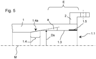
- Figure 5 shows a schematic diagram of a shaft 1 with the recess 1.1.
- the recess 1.1 has an inner surface 1.3 running around the central axis M with a diameter Ds for supporting a sensor arrangement with a sensor (not shown).
- Different profiles are provided on the left and right adjacent to the inner surface 1.3 in the axial direction, each of which deviates at least partially from the diameter Ds in the radial direction. The deviation enables a positive connection in the axial direction with a component that is inserted into the recess 1.1.
- the profile provided further inside (left) in the recess 1.1 forms a circumferential section 1.4 with a reduced diameter compared to the inner surface 1.3, which has a conical surface 1.4a set at an angle a, the angle a preferably having a dimension between 1.1 and 1.5 degrees [°]. Angles are preferably provided in the order of magnitude that are usually used for Morse tapers.
- the profile arranged further outwards (on the right) in the recess 1.1 is designed as an internal thread 1.5 and is used to screw in a component (not shown in detail) for the axial fixation of a sensor arrangement 3.
- the component has a parallel conical surface corresponding to the conical surface 1.4a.
Landscapes
- Engineering & Computer Science (AREA)
- General Engineering & Computer Science (AREA)
- Mechanical Engineering (AREA)
- Arrangements For Transmission Of Measured Signals (AREA)
Abstract
Description
- Die Erfindung bezieht sich auf eine Welle mit einer Einrichtung zur mittelbaren Erfassung und Übertragung von Messdaten von der Welle, die aus einer mechanischen Beanspruchung der Welle resultieren, wobei die Welle mit einer Mittelachse als Teil einer Kardanwelle einen ersten Endabschnitt aufweist und die Welle mit einer Gabel zum Übertragen von Drehmomenten auf einen Kreuzzapfen kombiniert ist und die Welle mit der Gabel ein Wellenende bildet. Das Wellenende wird entsprechend durch den Endabschnitt und die Gabel gebildet.
- Gattungsgemäße Kardanwellen als eine spezielle Form der Gelenkwellen umfassen ein oder zwei Kreuzgelenke (Kardangelenke) zum Knicken, Abwinkeln oder Beugen des Wellenstrangs sowie zur Weiterleitung und Übertragen eines Drehmoments an beidseitig an das Kreuzgelenk anschließende Wellen. Das Kreuzgelenk umfasst in den bevorzugten Ausführungsformen zwei Gabeln, die über einen Kreuzzapfen mit zwei rechtwinklig gekreuzten Zapfenpaaren miteinander verbunden sind. An die jeweilige Gabel schließt eine Welle an, die über den bezüglich der Gabel gegenüberliegenden zweiten Endabschnitt der Welle das Drehmoment über eine Verzahnung oder einen Flansch auf ein weiteres Bauteil im Antriebsstrang überträgt. In den meisten Anwendungsformen schließt an die Gabel eine Gabelwelle, also eine Welle mit einer Außenverzahnung oder eine Hohlwelle mit einer Innenverzahnung an. Eine Gabelwelle und eine Hohlwelle sind zwecks eines Längenausgleichs zueinander verschiebbar gelagert und bilden zusammen ein Schiebelager oder eine Verschiebung.
- Aus der
WO 2022/017928 A1 ist bereits ein Kreuzgelenk mit einer anschließenden Hohlwelle bekannt, bei der in dem Hohlraum der Hohlwelle an die Verzahnung anschließend ein Sensor angeordnet ist. Nach derDE 11 2017 000 605 T5 ist eine gattungsgemäße Gabelwelle bekannt, bei der der Sensor auf der Außenseite der Gabelwelle im Bereich der Außenverzahnung unmittelbar vor der Gabel in einer für den Sensor vorgesehene und von außen in radialer Richtung eingebrachte Vertiefung angeordnet ist. Die Positionierung der Sensoranordnung erfolgt auf der Außenseite einer Gabelwelle in einem Bereich in axialer Richtung zwischen der Außenverzahnung und der Gabel. - Der Erfindung liegt die Aufgabe zugrunde, eine Einrichtung zur Erfassung und Übertragung von Messdaten von einer Welle derart auszubilden und anzuordnen, dass sie einfach zu fertigen und der Sensor gleichzeitig besser gegen äußere Einflüsse geschützt ist.
- Gelöst wird die Aufgabe erfindungsgemäß dadurch, dass in der Welle oder im Endabschnitt eine Ausnehmung zur Aufnahme zumindest eines Teils einer Sensoranordnung vorgesehen ist, wobei die Ausnehmung von außen von der Seite der Gabel und in Richtung der Mittelachse in das Wellenende eingebracht wird. Nachteilig ist dabei, dass die Gabelwelle, in die bei einer Kardanwelle das Drehmoment antriebsseitig eingeleitet wird, durch die Ausnehmung in ihrer Festigkeit geschwächt wird. Die geringere Festigkeit kann durch Einpressen eines Bauteils in die Ausnehmung kompensiert werden. Das Bauteil kann bei entsprechender Steifigkeit des Bauteils und bei entsprechend hohem, nach dem Einpressen erzeugten radialen Druck das zu übertragende Drehmoment und damit die reduzierte Festigkeit zumindest teilweise kompensieren. Die Ausnehmung ist im einfachsten Fall in Form einer Bohrung in die Gabelwelle eingebracht. In eine Bohrung lassen sich Bauteile einer Sensoranordnung sowie die Sensoranordnung selbst Einpressen.
- Die Gabel kann dabei entweder mit einer Gabelwelle mit Außenverzahnung oder mit einer Hohlwelle mit Innenverzahnung kombiniert sein. Durch die von der Gabelseite aus stirnseitige Ausnehmung ist der Raum für die Sensoranordnung um die Mittelachse herum durch die Welle und zudem auch in beiden axialen Richtungen vor mechanischen Einflüssen geschützt und wird nicht durch Betriebsstoffe oder Schmutz beeinträchtigt. Auf der Seite des Kreuzgelenks, auf der die Ausnehmung am Wellenende mündet, schützt der Kreuzzapfen und die beiden an dem Kreuzzapfen angreifenden Gabeln vor mechanischen Einflüssen von außen. Die Ausnehmung beeinflusst aufgrund ihrer erfindungsgemäßen Anordnung weder die Größe noch die Bauart der Welle, weil die Geometrie der Gabelwelle auf der Seite der Gabel immer die gleiche ist. Variabel sind die Geometrien bezüglich der weiteren Bauteile einer Kardanwelle, wie beispielsweise die Länge der Zahnwelle oder des Hohlrohrs. Erfindungsgemäß kann durch die Positionierung der Ausnehmung auf der Gabelseite auch bei sehr kurzen Wellen und bei Anwendungen ohne eine Hohlwelle eine Sensoranordnung positioniert werden. Vom Gegenstand der Erfindung ist zunächst noch keine Sensoranordnung erfasst. Alle beschriebenen Richtungen, wie beispielsweise axial, koaxial, radial, umlaufend oder angestellt beziehen sich jeweils relativ zu der Mittelachse.
- Für das Einpressen von Bauteilen zur Kompensation der Festigkeit hat die Ausnehmung eine vorteilhafte Geometrie. Insbesondere eine um die Mittelachse umlaufende Innenfläche mit einem Durchmesser zum Lagern eines Sensors und ein an die Innenfläche in axialer Richtung angrenzendes Profil, das zumindest teilweise gegenüber dem Durchmesser in radialer Richtung abweicht. Das Profil wirkt bevorzugt in axialer Richtung formschlüssig, sodass beispielsweise durch Kegelflächen mit sehr geringer Steigung relativ viel Druck in radialer Richtung erzeugt und damit auch durch erhöhte Reibung und Kraftschluss größere Drehmomente von der Welle auf die Bauteile einer Sensoranordnung übertragen werden können.
- Das Profil bildet besonders bevorzugt einen umlaufenden und im Durchmesser gegenüber der Innenfläche reduzierten Abschnitt, der eine um einen Winkel angestellte Konusfläche aufweist, wobei der Winkel ein Maß von mindestens 0,5 Grad [°] und maximal 3,0 Grad [°] beträgt. Das Profil dient zur axialen Fixierung eines Bauteils der Sensoranordnung, in dem es durch den geringen Winkel entsprechenden großen radialen Druck erzeugt und eine Übertragung sowie Kompensation von Kräften erlaubt.
- In einer bevorzugten alternativen Bauform ist das Profil als Innengewinde oder als Innenverzahnung ausgebildet, die zum Einschrauben oder Einschieben eines Bauteils zur axialen Fixierung einer Sensoranordnung dienen. Durch das Innengewinde lässt sich ein Bauteil Einschrauben, dass mit entsprechenden Konusflächen einen extrem hohen radialen Druck erzeugen kann. Ähnlich verhält es sich mit einer auf der Innenfläche vorgesehenen Innenverzahnung der Welle, die in Verbindung mit einem eingepressten Bauteil mit einer Außenverzahnung ebenfalls eine Kompensation von Kräften der zu übertragenen Drehmomente ermöglicht.
- Für die erfindungsgemäße Lösung kommen im Wesentlichen zwei Bauformen von Wellen mit einer Gabel in Betracht. Bei der häufigsten Bauform bildet die Welle mit der Gabel ein einteiliges Schmiedeteil, bei dem die Gabel in axialer Richtung an die Welle anschließt, wobei die Ausnehmung koaxial zu der Mittelachse durch die Gabel hindurch geführt und stirnseitig in den ersten Endabschnitt der Welle eingebracht ist. Grundsätzlich ist die Ausnehmung von außen von der Seite der Gabel und in Richtung zu der Mittelachse in das Wellenende eingebracht. Zur Lösung der Aufgabe ist es aber nicht zwingend erforderlich, dass die Ausnehmung koaxial zu der Mittelachse angeordnet ist. In technisch vorteilhaften Ausführungsformen ist die Ausnehmung jedoch zusätzlich koaxial zu der Mittelachse angeordnet. Die zu der Mittelachse koaxiale Anordnung der Ausnehmung ermöglicht eine entsprechend koaxiale Positionierung der Sensoranordnung. Diese koaxiale Anordnung hat den Vorteil, dass durch die Masse der Sensoranordnung äußerst geringe Unwuchten entstehen. Aufgrund der Durchdringung der Gabel kann der Sensor von dem Wellenende in die Welle eingebracht werden. Dafür ist es notwendig, auch in der Gabel eine Ausnehmung vorzusehen. Der Teil der Ausnehmung in der Gabel bietet erfindungsgemäß Stauraum für Teile der Sensoranordnung.
- Bei einer alternativen gattungsgemäßen, jedoch zweiteiligen Bauform von Kardanwellen wird die Gabel auf die Welle aufgesetzt, sodass die Welle in die Gabel eintaucht. Dabei ist die Welle über eine Verzahnung in Umfangsrichtung mit der Gabel gekoppelt. Zur Positionierung der Sensoranordnung ist es vorteilhaft, dass die Ausnehmung direkt stirnseitig und koaxial zu der Mittelachse in den ersten Endabschnitt der Welle eingebracht ist. Eine Bearbeitung der Gabel ist in diesem Fall nicht notwendig. Auch bei dieser Ausführungsform ist zusätzlich zu der Richtung von der Gabelseite her die koaxiale Ausrichtung gefordert. Axiale und koaxiale Richtungen und Anordnungen sind im Rahmen der Erfindung grundsätzlich in Bezug zu der Mittelachse der Welle zu verstehen. Die axiale Richtung von der Gabel zur Welle hin, wird als die Richtung von außen bezeichnet. Der gegenüber den bekannten Lösungen zur Verfügung stehende und wesentlich kleinere Bauraum in der gabelseitigen Ausnehmung kann bei der einteiligen Bauform erfindungsgemäß dadurch kompensiert werden, dass Teile der Sensoranordnung wie beispielsweise die Antenne und/oder eine Batterie als Energieversorgung zumindest teilweise unmittelbar stirnseitig vor der Welle in der Gabel positioniert werden. Die Ausnehmung in der Gabel kann zur offenen Seite beziehungsweise nach außen hin im Durchmesser wesentlich größer dimensioniert werden als in der Welle, weil in diesem vorderen Bereich der Gabel keine wesentliche Übertragung des Drehmoments von der Welle über die Gabel auf den Kreuzzapfen erfolgt. Das Drehmoment wird im Wesentlichen unmittelbar nach dem Übergang von der Welle zu der Gabel im hinteren Bereich der Gabel übertragen. Aufgrund des größeren Durchmessers ist es möglich, eine in der Fläche größere Antenne einzusetzen, sodass die Datenübertragung optimiert werden kann.
- Aufgrund der bei einem Kardangelenk mit einem Kreuzzapfen herstellungsbedingten Geometrie, ist entlang der Mittelachse zwischen der Gabel bzw. der Stirnseite der Welle am ersten Endabschnitt und dem Kreuzzapfen ein Abstand von durchschnittlich mehr als einem Zentimeter gegeben. Durch diesen Abstand ist ein Freiraum vorhanden, der eine störungsfreie Übertragung der elektromagnetischen Signale ermöglicht, die durch die Antenne abgegeben werden. Dieser Freiraum ermöglicht es beispielsweise auch, ohne Demontage des Kardangelenks die Sensoranordnung zu warten. Über diesen Freiraum lässt sich ein Verschluss für die Ausnehmung beispielsweise in Form eines Deckels und Teile der Sensoranordnung montieren und demontieren. Die Erreichbarkeit einer Ladebuchse eines Akkus als Energieversorgung des Sensors und insbesondere das Aufsetzen eines Steckers ist durch diesen Freiraum gewährleistet. Erfindungsgemäß wird der Vorteil durch die Wahl der Position der Ausnehmung nutzbar gemacht, weil die Zugänglichkeit zu dem Kardangelenk und zu dem Freiraum bei eingebauter Gabelwelle in diesem Bereich ohnehin gewährleistet ist. Die Lager des Kreuzzapfens sind zwecks einer Wartung zum Abschmieren mit einer Fettpresse gut erreichbar.
- Für das Messen und Erfassen von Daten ist es in einem weiteren Schritt der Erfindung vorteilhaft, wenn die Einrichtung eine Sensoranordnung zur Erfassung und Übertragung der Messdaten umfasst, wobei ein Sensor als Teil der Sensoranordnung in der Ausnehmung positioniert und an der Oberfläche der Ausnehmung befestigt ist. Die Ausnehmung ist grundsätzlich geeignet, eine Sensoranordnung zu positionieren. Die Kombination einer solchen Welle mit einer Sensoranordnung ermöglicht es, Messwerte zu erfassen und die Sensoranordnung zu schützen.
- Hinsichtlich der Datenerfassung kann es vorteilhafterweise vorgesehen sein, dass die Sensoranordnung zudem eine Antenne und eine Energieversorgung als Bauteil aufweist, wobei zumindest die Antenne in einem Bereich der Ausnehmung angeordnet ist, der in axialer Richtung an dem vorderen Ende der Ausnehmung und innerhalb der Gabel liegt. Die Antenne ist zum Übertragen der Messdaten vorgesehen. Bei bevorzugten Ausführungsformen ist zusätzlich ein Ladekabel mit einer Ladebuchse für einen Akku als Energieversorgung vorgesehen. In der Ausnehmung lassen sich verschiedenste Bauteile in axialer Richtung hintereinander positionieren. Von großem Interesse sind die Messdaten der Welle unmittelbar am Ende vor dem Übergang zu der Gabel. Die Positionierung des Sensors an dieser Stelle erlaubt es, die Antenne noch weiter nach außen direkt an der Öffnung der Ausnehmung in dem Bereich der Gabel zu platzieren. Für die Energieversorgung ist die Position ganz hinten in der Ausnehmung hinter dem Sensor vorgesehen.
- In Bezug auf die Datenübertragung kann für die vorliegende Erfindung vorteilhaft sein, wenn die Ausnehmung in dem Bereich innerhalb der Gabel einen größeren Durchmesser als in der Welle aufweist. Durch die Vergrößerung des Durchmessers lässt sich eine größere Antenne einsetzen, durch deren Größe die Datenübertragung präziser und leistungsstärker ist.
- Im Zusammenhang mit der Herstellung einer einfachen Ausnehmung kann es von Vorteil sein, wenn die Ausnehmung als Loch, als Sacklochbohrung oder als Durchgangsbohrung ausgebildet ist, wobei die Ausnehmung eine Länge zwischen 20 mm und 280 mm oder zwischen 160 mm und 200 mm aufweist. Eine Bohrung als einfachste Ausführungsform lässt sich als Sacklochbohrung oder als Durchgangsbohrung einbringen. Durchgangsbohrungen können bei sehr kurzen Wellen Anwendung finden, sodass die Bohrung bis zu dem Ende der Welle geführt ist, das gegenüber der Gabel angeordnet ist. Neben Bohrungen wäre es auch möglich, die Ausnehmung durch Erodieren herzustellen.
- Hinsichtlich bestmöglicher Messergebnisse kann es vorteilhaft sein, wenn die innere Oberfläche der Ausnehmung bezüglich des Durchmessers eine Maßtoleranz von im Mittel zwischen + 1/100 mm und + 6/100 mm aufweist. Die Maßtoleranz entspricht bevorzugt dem Wert H7 der gängigen Toleranztabellen. Auch ist es vorteilhaft, dass die innere Oberfläche der Ausnehmung bezüglich der Rundheit eine Maßtoleranz von maximal 0,03 mm bis 0,2 mm und/oder bezüglich der Koaxialität eine Maßtoleranz von maximal 0,05 mm bis 0,2 mm und/oder bezüglich der Rauheit einen Mittenrauwert Ra zwischen 0,4 µm und 32 µm aufweist.
- In Bezug auf die Gestaltung der Welle gibt es erfindungsgemäß keine Grenzen, weshalb es vorteilhaft ist, dass die Welle als Gabelwelle oder als Hohlwelle oder als Welle ohne eine Verzahnung ausgebildet ist oder ein Bauteil einer Doppelgelenkwelle bildet. Die Ausnehmung von der Gabelseite lässt sich in nahezu jede beliebige Welle einbringen.
- In Bezug auf den Einsatz der Welle zur Übertragung von Drehmomenten ist vorgesehen, dass in der Gabel ein Kreuzzapfen und an dem Kreuzzapfen ein Flansch mit einer Gabel gelagert ist. Die Welle selbst ist über eine Verschiebung mit einer weiteren Welle kombiniert, über die das Drehmoment über ein weiteres Kardangelenk oder eine sonstige Verbindung übertragen wird.
- Weitere Vorteile und Einzelheiten der Erfindung sind in den Patentansprüchen und in der Beschreibung erläutert und in den Figuren dargestellt. Es zeigen
- Figur 1
- eine Schnittansicht einer Gabelwelle mit einer Ausnehmung;
- Figur 2
- eine Ansicht gemäß
Figur 1 mit einer Sensoranordnung; - Figur 3
- eine perspektivische Ansicht einer Gabelwelle mit Blick auf das Wellenende;
- Figur 4
- eine Ansicht einer kompletten Kardanwelle mit einer Gabelwelle und einer Hohlwelle;
- Figur 4a
- einen vergrößerten Ausschnitt gemäß
Figur 4 und - Figur 5
- eine Prinzipskizze einer Gabelwelle mit einer um die Mittelachse umlaufende Innenfläche mit unterschiedlichen Profilen.
- Die
Figuren 1-3 zeigen beispielhaft eine Gabelwelle, bei der von dem Wellenende E aus eine Ausnehmung 1.1 zum Einbringen einer Sensoranordnung 3 vorgesehen ist. Die Gabelwelle als Schmiedeteil besteht aus einer Welle 1 und einer Gabel 2. In dem im Schnitt dargestellten Bereich der Gabelwelle schließt die Gabel 2 an einen ersten Endabschnitt 1.2 der Welle 1 an die Welle 1 an. Das Ende der Welle 1 wird in den Figuren durch die rechtwinklig zur Mittelachse M der Welle 1 verlaufende gestrichelte Linie verdeutlicht. Der erste Endabschnitt 1.2 definiert zusammen mit der Gabel 2 das für die Positionierung der Sensoranordnung 3 maßgebliche Wellenende E der Gabelwelle. Das in Bezug zu der Gabel 2 gegenüberliegende Ende der Welle 1 bildet einen zweiten Endabschnitt der Welle 1. In diesem zweiten Endabschnitt der Welle 1 ist die Verzahnung perspektivisch dargestellt, die als Verbindung zu einer gattungsgemäßen Hohlwelle dient, welche inFigur 4 dargestellt ist. Die Gabelwelle und die Hohlwelle sind über die Verzahnungen zueinander verschiebbar gelagert. - Die Gabelwelle nach den
Figuren 1-4 ist ein einteiliges Schmiedeteil, bestehend aus der Welle 1 und der Gabel 2. Gabelwellen können auch als zweiteilige Bauteile gebildet sein (nicht dargestellt), bei denen die Gabel auf den ersten Endabschnitt der Welle aufgesetzt ist und die Gabel über eine Innenverzahnung mit der Welle verbunden ist. - Nach den hier dargestellten Ausführungsbeispielen ist die Ausnehmung 1.1 in Form einer Bohrung koaxial zu der Mittelachse M der Welle 1 positioniert und wurde von außen von dem Wellenende E aus durch die Gabel 2 und in den ersten Endabschnitt 1.2 der Welle 1 eingebracht. Die Ausnehmung 1.1 weist eine Länge L von 180 mm auf. An dieses Ende der Welle 1 schließt die Gabel 2 als Teil des Schmiedeteils körperlich an.
- Die weitere Lösung der Aufgabe umfasst die Positionierung eines Sensors unmittelbar am Ende des ersten Endabschnitts 1.2 der Welle 1. In den
Figuren 2 und 3 ist eine Sensoranordnung 3 dargestellt, die in die Ausnehmung 1.1 eingebracht ist. Die Sensoranordnung 3 umfasst einen Sensor 3.1, eine Antenne 3.2 und eine Energieversorgung 3.3 in Form eines wiederaufladbaren Akkus. Zum Aufladen des Akkus 3.3 ist eine Ladebuchse 3.4 mit einem Ladekabel vorgesehen, der nach außen hin am Anfang der Ausnehmung 1.1 positioniert ist. Der Sensor ist unmittelbar am Ende des ersten Endabschnitts 1.2 positioniert, an dem die Welle 1 in die Gabel 2 übergeht. Für die hier dargestellte Sensoranordnung 3 weist die Ausnehmung 1.1 in der Gabel gemäßFigur 1 in einem Bereich (G) am Anfang der Ausnehmung 1.1 einen Durchmesser Dg auf, der größer ist als der Durchmesser Dw der Ausnehmung 1.1 in der Welle. Dieser größere Durchmesser erlaubt wie in denFiguren 2 und 3 gezeigt die Positionierung einer im Durchmesser größeren Antenne 3.2. - In
Figur 4 ist eine komplette Kardanwelle dargestellt, bei der an die Gabel 2 ein Kreuzzapfen 2.1 anschließt, der wiederum über eine weitere Gabel 5.1 mit einem Flansch 5 gekoppelt ist. Auf dem dem Wellenende E gegenüberliegenden Ende der Welle 1 ist eine Hohlwelle 4 mit einer Innenverzahnung auf die Welle 1 aufgeschoben. Am Ende der Hohlwelle 4 ist eine Gabel 4.1 vorgesehen, die über einen weiteren Kreuzzapfen 2.1 mit einer weiteren Gabel 6.1 und einem daran anschließenden weiteren Flansch 6 gekoppelt ist. - Der im linken Bereich der
Figur 4 mit einem gestrichelten Kreis hervorgehobene Bereich ist inFigur 4a vergrößert dargestellt. Bei solchen üblichen Anordnungen von Kardanwellen ist in axialer Richtung im Bereich der Mittelachse M zwischen der Gabel 2 und dem Kreuzzapfen 2.1 ein Abstand von mehreren Millimetern oder meist mehr als einem Zentimeter vorgesehen. In diesem als Freiraum F bezeichneten Bereich sind gewöhnlich auch Schmiernippel zur Wartung der Lager der Kreuzzapfen 2.1 angeordnet. Aufgrund des durch den Abstand gegebenen Freiraums F ist die Ausnehmung 1.1 stirnseitig am Wellenende E sehr gut zugänglich. Damit ist ein Zugang zu der Sensoranordnung 3 gewährleistet, um beispielsweise das in der Ausnehmung 1.1 positionierte Ladekabel über die Ladebuchse 3.4 für den Akku 3.3 mit einem Ladegerät zu verbinden. Hierzu ist unmittelbar zu Beginn der Ausnehmung 1.1 im Bereich der Antenne 3.2 die Ladebuchse 3.4 vorgesehen. Ferner erlaubt dieser Freiraum F eine störungsfreie Übertragung der elektromagnetischen Signale der Antenne 3.2. -
Figur 5 zeigt eine Prinzipskizze einer Welle 1 mit der Ausnehmung 1.1. Die Ausnehmung 1.1 weist eine um die Mittelachse M umlaufende Innenfläche 1.3 mit einem Durchmesser Ds zum Lagern einer Sensoranordnung mit Sensor (nicht dargestellt) auf. An die Innenfläche 1.3 sind in axialer Richtung angrenzend links und rechts unterschiedliche Profile vorgesehen, die jeweils zumindest teilweise gegenüber dem Durchmesser Ds in radialer Richtung abweichen. Durch die Abweichung ist in axialer Richtung ein Formschluss mit einem Bauteil möglich, dass in die Ausnehmung 1.1 eingebracht wird. Das weiter innen (links) in der Ausnehmung 1.1 vorgesehene Profil bildet einen umlaufenden und im Durchmesser gegenüber der Innenfläche 1.3 reduzierten Abschnitt 1.4, der eine um einen Winkel a angestellte Konusfläche 1.4a aufweist, wobei der Winkel a ein Maß bevorzugt zwischen 1,1 und 1,5 Grad [°] aufweist. Bevorzugt sind Winkel in Größenordnungen vorgesehen, die üblicherweise bei Morsekegeln eingesetzt werden. Das in der Ausnehmung 1.1 weiter außen (rechts) angeordnete Profil ist als Innengewinde 1.5 ausgebildet ist und dient zum Einschrauben eines nicht näher dargestellten Bauteils zur axialen Fixierung einer Sensoranordnung 3. Das Bauteil weist einen zu der Konusfläche 1.4a korrespondierende parallele Konusfläche auf. -
- 1
- Welle
- 1.1
- Ausnehmung
- 1.2
- Endabschnitt
- 1.3
- Innenfläche (1.3)
- 1.4
- Abschnitt (1.4)
- 1.4a
- Konusfläche
- 1.5
- Innengewinde (1.5)
- 2
- Gabel
- 2.1
- Kreuzzapfen
- 3
- Sensoranordnung
- 3.1
- Sensor
- 3.2
- Antenne
- 3.3
- Energieversorgung
- 3.4
- Ladebuchse
- 4
- Hohlwelle
- 4.1
- Gabel
- 5
- Flansch
- 5.1
- Gabel
- 6
- Flansch
- 6.1
- Gabel
- Ds
- Durchmesser
- E
- Wellenende
- F
- Freiraum
- G
- Bereich
- L
- Länge
- M
- Mittelachse
Claims (15)
- Welle (1) mit einer Einrichtung zur mittelbaren Erfassung und Übertragung von Messdaten von der Welle (1), die aus einer mechanischen Beanspruchung der Welle (1) resultieren, wobei die Welle (1) mit einer Mittelachse (M) als Teil einer Kardanwelle einen ersten Endabschnitt (1.2) aufweist und die Welle (1) mit einer Gabel (2) zum Übertragen von Drehmomenten auf einen Kreuzzapfen (2.1) kombiniert ist und die Welle (1) mit der Gabel (2) ein Wellenende (E) bildet,
dadurch gekennzeichnet,
dass in der Welle (1) oder im Endabschnitt (1.2) eine Ausnehmung (1.1) zur Aufnahme zumindest eines Teils einer Sensoranordnung (3) vorgesehen ist, wobei die Ausnehmung (1.1) von außen von der Seite der Gabel (2) und in Richtung der Mittelachse (M) in das Wellenende (E) eingebracht ist. - Welle nach Anspruch 1,
dadurch gekennzeichnet,
dass die Ausnehmung (1.1)a) eine um die Mittelachse (M) umlaufende Innenfläche (1.3) mit einem Durchmesser (Ds) zum Lagern eines Sensors (3.1) aufweist undb) ein an die Innenfläche (1.3) in axialer Richtung angrenzendes Profil (1.4, 1.5) aufweist, das zumindest teilweise gegenüber dem Durchmesser (Ds) in radialer Richtung abweicht. - Welle nach Anspruch 1 oder 2,
dadurch gekennzeichnet,
dass das Profil einen umlaufenden und im Durchmesser gegenüber der Innenfläche (1.3) reduzierten Abschnitt (1.4) bildet, der eine um einen Winkel a angestellte Konusfläche (1.4a) aufweist, wobei der Winkel a ein Maß von mindestens 0,5 Grad [°] und maximal 3,0 Grad [°] beträgt. - Vorrichtung nach einem der vorhergehenden Ansprüche,
dadurch gekennzeichnet,
dass das Profil als Innengewinde (1.5) oder als Innenverzahnung ausgebildet ist und zum Einschrauben oder Einschieben eines Bauteils zur axialen Fixierung einer Sensoranordnung (3) dient. - Welle nach einem der vorhergehenden Ansprüche,
dadurch gekennzeichnet,
dass die Gabel (2) in axialer Richtung an die Welle (1) anschließt und mit der Welle (1) ein einteiliges Schmiedeteil bildet, wobei die Ausnehmung (1.1) koaxial zu der Mittelachse (M) durch die Gabel (2) hindurch geführt und stirnseitig in den ersten Endabschnitt (1.2) der Welle (1) eingebracht ist. - Welle nach einem der vorhergehenden Ansprüche,
dadurch gekennzeichnet,
dass die Gabel (2) auf die Welle (1) aufgesetzt und die Ausnehmung (1.1) direkt stirnseitig und koaxial zu der Mittelachse (M) in den ersten Endabschnitt (1.2) der Welle (1) eingebracht ist. - Welle nach einem der vorhergehenden Ansprüche,
dadurch gekennzeichnet,
dass die Einrichtung eine Sensoranordnung (3) zur Erfassung und Übertragung der Messdaten umfasst, wobei ein Sensor (3.1) als Teil der Sensoranordnung (3) in der Ausnehmung (1.1) befestigt ist. - Welle nach Anspruch 4,
dadurch gekennzeichnet,
dass die Sensoranordnung (3) zudem eine Antenne (3.2) und eine Energieversorgung (3.3) als Bauteil aufweist, wobei zumindest die Antenne (3.2) in einem Bereich (G) der Ausnehmung (1.1) angeordnet ist, der in axialer Richtung an dem vorderen Ende der Ausnehmung (1.1) und innerhalb der Gabel (2) liegt. - Welle nach Anspruch 5,
dadurch gekennzeichnet,
dass die Ausnehmung (1.1) in dem Bereich (G) innerhalb der Gabel (2) zumindest teilweise einen Durchmesser (Dg) aufweist, der gegenüber dem Durchmesser (Ds) vergrößert ist. - Welle nach einem der vorhergehenden Ansprüche,
dadurch gekennzeichnet,
dass die Ausnehmung (1.1) als Loch, als Sacklochbohrung oder als Durchgangsbohrung ausgebildet ist, wobei die Ausnehmung (1.1) eine Länge (L) zwischen 20 mm und 280 mm oder zwischen 160 mm und 200 mm aufweist. - Welle nach einem der vorhergehenden Ansprüche,
dadurch gekennzeichnet,
dass die innere Oberfläche der Ausnehmung (1.1) bezüglicha) des Durchmessers (Dw) eine Maßtoleranz von im Mittel zwischen + 1/100 mm und + 6/100 mm aufweist und/oderb) der Rundheit eine Maßtoleranz von maximal 0,03 mm bis 0,2 mm und/oderc) der Koaxialität eine Maßtoleranz von maximal 0,05 mm bis 0,2 mm und/oderd) der Rauheit einen Mittenrauwert Ra zwischen 0,4 µm und 32 µm aufweist. - Welle nach einem der vorhergehenden Ansprüche,
dadurch gekennzeichnet,
dass die Welle (1) als Gabelwelle oder als Hohlwelle oder als Welle (1) ohne eine Verzahnung ausgebildet ist oder die Welle (1) ein Bauteil einer Doppelgelenkwelle bildet. - Welle nach einem der vorhergehenden Ansprüche,
dadurch gekennzeichnet,
dass in der Gabel (2) ein Kreuzzapfen (2.1) und an dem Kreuzzapfen (2.1) ein Flansch (5) mit einer Gabel (5.1) gelagert ist. - System bestehend aus einer Welle (1) nach einem der vorhergehenden Ansprüche und einem oder mehreren Bauteilen zum Anschließen an die Welle (1) in Form von Kreuzzapfen, Gabelwellen, Hohlwellen, Getriebewellen, Kardangelenken, Flanschen und Getrieben zum Übertragen von Drehmomenten.
- Verwendung einer Ausnehmung (1.1) in einer Welle (1) zur Aufnahme zumindest eines Teils einer Sensoranordnung (3), wobei die Welle (1) mit einer Mittelachse (M) als Teil einer Kardanwelle einen ersten Endabschnitt (1.2) aufweist und die Welle (1) mit einer Gabel (2) zum Übertragen von Drehmomenten auf einen Kreuzzapfen (2.1) derart kombiniert ist, dass die Welle (1) mit der Gabel (2) ein Wellenende (E) bilden und die Ausnehmung (1.1) von außen und koaxial zu der Mittelachse (M) stirnseitig in das Wellenende (E) in den ersten Endabschnitt (1.2) der Welle (1) eingebracht ist.
Applications Claiming Priority (1)
| Application Number | Priority Date | Filing Date | Title |
|---|---|---|---|
| DE102023120776.8A DE102023120776A1 (de) | 2023-08-04 | 2023-08-04 | Gabelwelle |
Publications (2)
| Publication Number | Publication Date |
|---|---|
| EP4506582A1 true EP4506582A1 (de) | 2025-02-12 |
| EP4506582B1 EP4506582B1 (de) | 2025-11-05 |
Family
ID=92212647
Family Applications (1)
| Application Number | Title | Priority Date | Filing Date |
|---|---|---|---|
| EP24192689.8A Active EP4506582B1 (de) | 2023-08-04 | 2024-08-02 | Gabelwelle |
Country Status (2)
| Country | Link |
|---|---|
| EP (1) | EP4506582B1 (de) |
| DE (1) | DE102023120776A1 (de) |
Citations (8)
| Publication number | Priority date | Publication date | Assignee | Title |
|---|---|---|---|---|
| DE8206801U1 (de) * | 1982-03-11 | 1984-10-25 | J.M. Voith Gmbh, 7920 Heidenheim | Gelenkwelle mit Richtvorrichtung |
| US20080078253A1 (en) * | 2006-09-28 | 2008-04-03 | Taylor Blackwood | Apparatus and method for measuring torque and power |
| DE102013212052A1 (de) * | 2013-06-25 | 2015-01-08 | Schaeffler Technologies Gmbh & Co. Kg | Vorrichtung zur Drehmomentmessung |
| DE112017000605T5 (de) | 2016-03-08 | 2018-10-11 | Scania Cv Ab | Messvorrichtung zum Bewerten eines Drehmomentparameters eines Fahrzeugs und Verfahren zum Bewerten eines Drehmomentparameters eines Fahrzeugs |
| US20210165014A1 (en) * | 2018-06-20 | 2021-06-03 | Tirsan Kardan Sanayi Ve Ticaret Anonim Sirketi | A system for determining revolutions in drive shafts, a cardan shaft related to said system and determining method thereof |
| FR3104256A3 (fr) * | 2019-12-05 | 2021-06-11 | Ti̇rsan Kardan Sanayi̇ Ve Ti̇caret Anoni̇m Şi̇rketi̇ | Element de mesure |
| WO2022017928A1 (de) | 2020-07-24 | 2022-01-27 | Core Sensing Gmbh | Messeinrichtung zur anordnung in einem zylinderförmigen innenraumabschnitt eines hohlkörpers |
| US20230204079A1 (en) * | 2020-12-24 | 2023-06-29 | Tirsan Kardan Sanayi Ve Ticaret Anonim Sirketi | A circuit carrier for cardan shafts |
Family Cites Families (3)
| Publication number | Priority date | Publication date | Assignee | Title |
|---|---|---|---|---|
| EP0254754A1 (de) * | 1986-07-26 | 1988-02-03 | Carl Schenck Ag | Verfahren zur Ermittlung eines Drehmomentes |
| JP4083591B2 (ja) * | 2003-02-07 | 2008-04-30 | トヨタ自動車株式会社 | トルク検出装置の取り付け構造 |
| DE102010045448B4 (de) * | 2010-09-15 | 2018-01-11 | Sew-Eurodrive Gmbh & Co Kg | Anordnung zur Erfassung des von einer Welle durchgeleiteten Drehmoments und Getriebe |
-
2023
- 2023-08-04 DE DE102023120776.8A patent/DE102023120776A1/de active Pending
-
2024
- 2024-08-02 EP EP24192689.8A patent/EP4506582B1/de active Active
Patent Citations (8)
| Publication number | Priority date | Publication date | Assignee | Title |
|---|---|---|---|---|
| DE8206801U1 (de) * | 1982-03-11 | 1984-10-25 | J.M. Voith Gmbh, 7920 Heidenheim | Gelenkwelle mit Richtvorrichtung |
| US20080078253A1 (en) * | 2006-09-28 | 2008-04-03 | Taylor Blackwood | Apparatus and method for measuring torque and power |
| DE102013212052A1 (de) * | 2013-06-25 | 2015-01-08 | Schaeffler Technologies Gmbh & Co. Kg | Vorrichtung zur Drehmomentmessung |
| DE112017000605T5 (de) | 2016-03-08 | 2018-10-11 | Scania Cv Ab | Messvorrichtung zum Bewerten eines Drehmomentparameters eines Fahrzeugs und Verfahren zum Bewerten eines Drehmomentparameters eines Fahrzeugs |
| US20210165014A1 (en) * | 2018-06-20 | 2021-06-03 | Tirsan Kardan Sanayi Ve Ticaret Anonim Sirketi | A system for determining revolutions in drive shafts, a cardan shaft related to said system and determining method thereof |
| FR3104256A3 (fr) * | 2019-12-05 | 2021-06-11 | Ti̇rsan Kardan Sanayi̇ Ve Ti̇caret Anoni̇m Şi̇rketi̇ | Element de mesure |
| WO2022017928A1 (de) | 2020-07-24 | 2022-01-27 | Core Sensing Gmbh | Messeinrichtung zur anordnung in einem zylinderförmigen innenraumabschnitt eines hohlkörpers |
| US20230204079A1 (en) * | 2020-12-24 | 2023-06-29 | Tirsan Kardan Sanayi Ve Ticaret Anonim Sirketi | A circuit carrier for cardan shafts |
Also Published As
| Publication number | Publication date |
|---|---|
| DE102023120776A1 (de) | 2025-02-06 |
| EP4506582B1 (de) | 2025-11-05 |
Similar Documents
| Publication | Publication Date | Title |
|---|---|---|
| DE69636727T2 (de) | Gleichlaufgelenke | |
| EP2167827B1 (de) | Verbindungsanordnung | |
| EP3156666B1 (de) | Befestigungssystem für ein maschinenelement | |
| DE102012221232A1 (de) | Lageranordnung, insbesondere für Spannlager | |
| EP1664564B1 (de) | Anbindungssystem für eine welle an ein gelenk | |
| DE102008024070B4 (de) | Adapter für eine Ausgangswelle eines Getriebes | |
| DE10315884B4 (de) | Längs eingebauter Allrad-Antriebsstrang | |
| DE19836259C2 (de) | Drehfeste Welle-Nabe-Verbindung | |
| DE19803304C5 (de) | Bohrgestänge zum Drehschlagbohren, insbesondere zum Überlagerungsbohren | |
| AT517763B1 (de) | Anordnung zur Drehverbindung einer Belastungsmaschine eines Prüfstandes mit einem Prüfling | |
| EP1281884A2 (de) | Baureihe von Wellen und Verfahren zur Fertigung | |
| EP2187097A1 (de) | Linearantrieb | |
| DE10107605A1 (de) | Flanschmitnehmer | |
| EP4506582B1 (de) | Gabelwelle | |
| EP3169913B1 (de) | Wellgetriebe mit trockenlauf | |
| EP3819136A1 (de) | Radlagereinheit für ein kraftfahrzeug sowie verfahren zum herstellen einer radlagereinheit | |
| EP3828444A1 (de) | Getriebe | |
| DE10162713B4 (de) | Vorrichtung zur Verbindung zweier Bauteile, insbesondere zweier Werkzeugteile | |
| DE10162910B4 (de) | Klemmspaltmutter | |
| EP3913261B1 (de) | Ankoppelvorrichtung zum drehmoment-übertragenden ankoppeln einer antriebsvorrichtung an ein getriebe | |
| EP0489007A1 (de) | Drehfeste flanschverbindung | |
| EP4403740A1 (de) | Gewindeverbindung | |
| EP4036355A1 (de) | Aktuierungsvorrichtung, schliesszylinder, schliesssystem und verfahren | |
| DE102011088327A1 (de) | Kreuzgelenkwelle | |
| EP1886047B1 (de) | Differentialanordnung mit montageöffnungen |
Legal Events
| Date | Code | Title | Description |
|---|---|---|---|
| PUAI | Public reference made under article 153(3) epc to a published international application that has entered the european phase |
Free format text: ORIGINAL CODE: 0009012 |
|
| STAA | Information on the status of an ep patent application or granted ep patent |
Free format text: STATUS: THE APPLICATION HAS BEEN PUBLISHED |
|
| AK | Designated contracting states |
Kind code of ref document: A1 Designated state(s): AL AT BE BG CH CY CZ DE DK EE ES FI FR GB GR HR HU IE IS IT LI LT LU LV MC ME MK MT NL NO PL PT RO RS SE SI SK SM TR |
|
| STAA | Information on the status of an ep patent application or granted ep patent |
Free format text: STATUS: REQUEST FOR EXAMINATION WAS MADE |
|
| 17P | Request for examination filed |
Effective date: 20250430 |
|
| GRAP | Despatch of communication of intention to grant a patent |
Free format text: ORIGINAL CODE: EPIDOSNIGR1 |
|
| STAA | Information on the status of an ep patent application or granted ep patent |
Free format text: STATUS: GRANT OF PATENT IS INTENDED |
|
| RIC1 | Information provided on ipc code assigned before grant |
Ipc: F16D 3/38 20060101AFI20250527BHEP |
|
| INTG | Intention to grant announced |
Effective date: 20250626 |
|
| GRAS | Grant fee paid |
Free format text: ORIGINAL CODE: EPIDOSNIGR3 |
|
| GRAA | (expected) grant |
Free format text: ORIGINAL CODE: 0009210 |
|
| STAA | Information on the status of an ep patent application or granted ep patent |
Free format text: STATUS: THE PATENT HAS BEEN GRANTED |
|
| AK | Designated contracting states |
Kind code of ref document: B1 Designated state(s): AL AT BE BG CH CY CZ DE DK EE ES FI FR GB GR HR HU IE IS IT LI LT LU LV MC ME MK MT NL NO PL PT RO RS SE SI SK SM TR |
|
| REG | Reference to a national code |
Ref country code: CH Ref legal event code: F10 Free format text: ST27 STATUS EVENT CODE: U-0-0-F10-F00 (AS PROVIDED BY THE NATIONAL OFFICE) Effective date: 20251105 Ref country code: GB Ref legal event code: FG4D Free format text: NOT ENGLISH |
|
| REG | Reference to a national code |
Ref country code: DE Ref legal event code: R096 Ref document number: 502024000371 Country of ref document: DE |
|
| REG | Reference to a national code |
Ref country code: IE Ref legal event code: FG4D Free format text: LANGUAGE OF EP DOCUMENT: GERMAN |
|
| REG | Reference to a national code |
Ref country code: NL Ref legal event code: MP Effective date: 20251105 |
|
| PG25 | Lapsed in a contracting state [announced via postgrant information from national office to epo] |
Ref country code: ES Free format text: LAPSE BECAUSE OF FAILURE TO SUBMIT A TRANSLATION OF THE DESCRIPTION OR TO PAY THE FEE WITHIN THE PRESCRIBED TIME-LIMIT Effective date: 20251105 |
|
| REG | Reference to a national code |
Ref country code: LT Ref legal event code: MG9D |
|
| PG25 | Lapsed in a contracting state [announced via postgrant information from national office to epo] |
Ref country code: NO Free format text: LAPSE BECAUSE OF FAILURE TO SUBMIT A TRANSLATION OF THE DESCRIPTION OR TO PAY THE FEE WITHIN THE PRESCRIBED TIME-LIMIT Effective date: 20260205 |
|
| PG25 | Lapsed in a contracting state [announced via postgrant information from national office to epo] |
Ref country code: FI Free format text: LAPSE BECAUSE OF FAILURE TO SUBMIT A TRANSLATION OF THE DESCRIPTION OR TO PAY THE FEE WITHIN THE PRESCRIBED TIME-LIMIT Effective date: 20251105 Ref country code: HR Free format text: LAPSE BECAUSE OF FAILURE TO SUBMIT A TRANSLATION OF THE DESCRIPTION OR TO PAY THE FEE WITHIN THE PRESCRIBED TIME-LIMIT Effective date: 20251105 |
|
| PG25 | Lapsed in a contracting state [announced via postgrant information from national office to epo] |
Ref country code: NL Free format text: LAPSE BECAUSE OF FAILURE TO SUBMIT A TRANSLATION OF THE DESCRIPTION OR TO PAY THE FEE WITHIN THE PRESCRIBED TIME-LIMIT Effective date: 20251105 |
|
| PG25 | Lapsed in a contracting state [announced via postgrant information from national office to epo] |
Ref country code: RS Free format text: LAPSE BECAUSE OF FAILURE TO SUBMIT A TRANSLATION OF THE DESCRIPTION OR TO PAY THE FEE WITHIN THE PRESCRIBED TIME-LIMIT Effective date: 20260205 |
|
| PG25 | Lapsed in a contracting state [announced via postgrant information from national office to epo] |
Ref country code: IS Free format text: LAPSE BECAUSE OF FAILURE TO SUBMIT A TRANSLATION OF THE DESCRIPTION OR TO PAY THE FEE WITHIN THE PRESCRIBED TIME-LIMIT Effective date: 20260305 |
|
| PG25 | Lapsed in a contracting state [announced via postgrant information from national office to epo] |
Ref country code: PT Free format text: LAPSE BECAUSE OF FAILURE TO SUBMIT A TRANSLATION OF THE DESCRIPTION OR TO PAY THE FEE WITHIN THE PRESCRIBED TIME-LIMIT Effective date: 20260305 |
|
| PG25 | Lapsed in a contracting state [announced via postgrant information from national office to epo] |
Ref country code: PL Free format text: LAPSE BECAUSE OF FAILURE TO SUBMIT A TRANSLATION OF THE DESCRIPTION OR TO PAY THE FEE WITHIN THE PRESCRIBED TIME-LIMIT Effective date: 20251105 |
|
| PG25 | Lapsed in a contracting state [announced via postgrant information from national office to epo] |
Ref country code: LV Free format text: LAPSE BECAUSE OF FAILURE TO SUBMIT A TRANSLATION OF THE DESCRIPTION OR TO PAY THE FEE WITHIN THE PRESCRIBED TIME-LIMIT Effective date: 20251105 |