EP4506555A1 - Cylinder head structure - Google Patents
Cylinder head structure Download PDFInfo
- Publication number
- EP4506555A1 EP4506555A1 EP23830762.3A EP23830762A EP4506555A1 EP 4506555 A1 EP4506555 A1 EP 4506555A1 EP 23830762 A EP23830762 A EP 23830762A EP 4506555 A1 EP4506555 A1 EP 4506555A1
- Authority
- EP
- European Patent Office
- Prior art keywords
- cylinder head
- wall
- cylinder
- head
- pair
- Prior art date
- Legal status (The legal status is an assumption and is not a legal conclusion. Google has not performed a legal analysis and makes no representation as to the accuracy of the status listed.)
- Pending
Links
Images



Classifications
-
- F—MECHANICAL ENGINEERING; LIGHTING; HEATING; WEAPONS; BLASTING
- F02—COMBUSTION ENGINES; HOT-GAS OR COMBUSTION-PRODUCT ENGINE PLANTS
- F02F—CYLINDERS, PISTONS OR CASINGS, FOR COMBUSTION ENGINES; ARRANGEMENTS OF SEALINGS IN COMBUSTION ENGINES
- F02F1/00—Cylinders; Cylinder heads
- F02F1/24—Cylinder heads
- F02F1/26—Cylinder heads having cooling means
- F02F1/36—Cylinder heads having cooling means for liquid cooling
- F02F1/40—Cylinder heads having cooling means for liquid cooling cylinder heads with means for directing, guiding, or distributing liquid stream
-
- F—MECHANICAL ENGINEERING; LIGHTING; HEATING; WEAPONS; BLASTING
- F01—MACHINES OR ENGINES IN GENERAL; ENGINE PLANTS IN GENERAL; STEAM ENGINES
- F01P—COOLING OF MACHINES OR ENGINES IN GENERAL; COOLING OF INTERNAL-COMBUSTION ENGINES
- F01P3/00—Liquid cooling
- F01P3/02—Arrangements for cooling cylinders or cylinder heads
-
- F—MECHANICAL ENGINEERING; LIGHTING; HEATING; WEAPONS; BLASTING
- F02—COMBUSTION ENGINES; HOT-GAS OR COMBUSTION-PRODUCT ENGINE PLANTS
- F02F—CYLINDERS, PISTONS OR CASINGS, FOR COMBUSTION ENGINES; ARRANGEMENTS OF SEALINGS IN COMBUSTION ENGINES
- F02F1/00—Cylinders; Cylinder heads
- F02F1/02—Cylinders; Cylinder heads having cooling means
- F02F1/10—Cylinders; Cylinder heads having cooling means for liquid cooling
-
- F—MECHANICAL ENGINEERING; LIGHTING; HEATING; WEAPONS; BLASTING
- F02—COMBUSTION ENGINES; HOT-GAS OR COMBUSTION-PRODUCT ENGINE PLANTS
- F02F—CYLINDERS, PISTONS OR CASINGS, FOR COMBUSTION ENGINES; ARRANGEMENTS OF SEALINGS IN COMBUSTION ENGINES
- F02F1/00—Cylinders; Cylinder heads
- F02F1/24—Cylinder heads
- F02F1/26—Cylinder heads having cooling means
- F02F1/36—Cylinder heads having cooling means for liquid cooling
-
- F—MECHANICAL ENGINEERING; LIGHTING; HEATING; WEAPONS; BLASTING
- F02—COMBUSTION ENGINES; HOT-GAS OR COMBUSTION-PRODUCT ENGINE PLANTS
- F02F—CYLINDERS, PISTONS OR CASINGS, FOR COMBUSTION ENGINES; ARRANGEMENTS OF SEALINGS IN COMBUSTION ENGINES
- F02F11/00—Arrangements of sealings in combustion engines
- F02F11/002—Arrangements of sealings in combustion engines involving cylinder heads
-
- F—MECHANICAL ENGINEERING; LIGHTING; HEATING; WEAPONS; BLASTING
- F01—MACHINES OR ENGINES IN GENERAL; ENGINE PLANTS IN GENERAL; STEAM ENGINES
- F01P—COOLING OF MACHINES OR ENGINES IN GENERAL; COOLING OF INTERNAL-COMBUSTION ENGINES
- F01P3/00—Liquid cooling
- F01P3/02—Arrangements for cooling cylinders or cylinder heads
- F01P2003/021—Cooling cylinders
-
- F—MECHANICAL ENGINEERING; LIGHTING; HEATING; WEAPONS; BLASTING
- F01—MACHINES OR ENGINES IN GENERAL; ENGINE PLANTS IN GENERAL; STEAM ENGINES
- F01P—COOLING OF MACHINES OR ENGINES IN GENERAL; COOLING OF INTERNAL-COMBUSTION ENGINES
- F01P3/00—Liquid cooling
- F01P3/02—Arrangements for cooling cylinders or cylinder heads
- F01P2003/024—Cooling cylinder heads
-
- F—MECHANICAL ENGINEERING; LIGHTING; HEATING; WEAPONS; BLASTING
- F02—COMBUSTION ENGINES; HOT-GAS OR COMBUSTION-PRODUCT ENGINE PLANTS
- F02F—CYLINDERS, PISTONS OR CASINGS, FOR COMBUSTION ENGINES; ARRANGEMENTS OF SEALINGS IN COMBUSTION ENGINES
- F02F7/00—Casings, e.g. crankcases
- F02F7/006—Camshaft or pushrod housings
- F02F2007/0063—Head bolts; Arrangements of cylinder head bolts
Definitions
- the present invention relates to a cylinder head assembled on a cylinder block by a plurality of fastening bolts.
- the cylinder block and the cylinder head are assembled across a gasket.
- the width between the cylinder and the cylinder, that is, between the cylinder bores is narrow and the width of the gasket is also inevitably narrow, the sealing force of a combustion gas is likely to decrease.
- the part between the adjacent fastening bolts in the cylinder head has a hollow cross section due to the presence of the cooling water channel, and the rigidity is likely to decrease.
- an axial force of the fastening bolts is less likely to be transmitted to the gasket through the cylinder head, and a gasket pressing force decreases, which may lead to a decrease in a sealing force.
- An object of the present invention is to provide a cylinder head structure that can increase the rigidity of an inter-bore corresponding portion positioned above between adjacent cylinders in a cylinder head and easily improve the sealing force of the inter-bore corresponding portion when enhancing the sealing force between a cylinder block and the cylinder head to improve the output of an engine.
- the vertical wall is newly provided between the pair of insertion walls, the length between the pair of insertion walls is greatly shortened (the length of the beam when the head upper wall is analogized as a double cantilever beam is greatly reduced), and therefore the strength and rigidity of the inter-bore corresponding portion positioned above between adjacent cylinders in the cylinder head can be greatly improved.
- Embodiments of a cylinder head structure according to the present invention will be described below with reference to the drawings regarding a case of an industrial diesel engine.
- an industrial diesel engine hereinafter, abbreviated as engine E
- the side provided with a cooling fan 10 is the front
- the side provided with a flywheel 7 is the rear
- the side provided with an intake port 30 [side provided with an intake manifold (not shown)] is the right
- an exhaust port 28 [side provided with an exhaust manifold (not shown)] is the left.
- a vertical wall 27 is added in an imaginary line to a conventional structure.
- a straight-four (multicylinder) engine E has a cylinder head 2 assembled on a cylinder block 1, a head cover 3 assembled on the cylinder head 2, and an oil pan 4 assembled under the cylinder block 1.
- 5 denotes a crankshaft
- 6 denotes a piston
- 7 denotes a flywheel
- 8 denotes a transmission belt
- 9 denotes a water pump
- 10 denotes a cooling fan
- 11 denotes a radiator.
- An upper portion of the cylinder block 1 is formed in a cylinder portion 1A embedding the piston 6.
- Cooling water w in a cooling device of this engine E generally flows in the following order. That is, as shown in Fig. 1 , the water pump 9 ⁇ the cylinder portion 1A of cylinder block 1 ⁇ the cylinder head 2 ⁇ a thermostat 12 ⁇ an upper hose 13 ⁇ the radiator 11 ⁇ a lower hose 14 ⁇ the water pump 9. There is also a route in which part of the cooling water w cools an oil cooler 16 from the cylinder head 2 through a supply passage 15 that is a dedicated route, and then returns to the water pump 9 through an exhaust passage 17.
- the cooling water w entering the cylinder portion 1A from the front flows also upward for each cylinder 1a while flowing rearward basically. Therefore, the cooling water w flows in upward from a cylinder cooling water channel 1W, which is a water jacket of the cylinder portion 1A, into a head cooling water channel 2W, which is a water jacket of the cylinder head 2, and flows from the rear to the front (to the water pump 9 of the front).
- a lower coupling wall 18, a middle coupling wall 19, and an upper coupling wall 20 that connect and integrate the adjacent cylinders 1a and 1a are provided in a state of crossing the cylinder cooling water channel 1W.
- the head cooling water channel 2W of the cylinder head 2 and the cylinder cooling water channel 1W of the cylinder portion 1A communicate with each other at a plurality of locations on an outside site of each cylinder 1a, and communicate with each other by two communication holes 21 and 22 on left and right positions between the adjacent cylinders 1a and 1a (between bores).
- the head cooling water channel 2W through which the cooling water w passes is internally formed in the cylinder head 2, and an inter-bore corresponding portion (also called “inter-cylinder portion") 2b positioned above between the adjacent cylinders 1a and 1a in the cylinder head 2 is shown in Figs. 2(A) and 4 .
- an inter-bore corresponding portion 2b an area between a pair of left and right insertion walls 24 having an insertion hole 2c through which a fastening bolt 23 passes, the area surrounded by a cylinder head bottom wall 26 and a head upper wall 25, is formed in the head cooling water channel 2W.
- a bottom surface 26a of the cylinder head bottom wall 26 is a surface placed on an upper surface 1b of the cylinder portion 1A via a gasket G, and the head upper wall 25 is an upper wall of a cylinder head on which the head cover 3 is placed.
- 28 in Figs. 3 to 5 denotes an exhaust port, and the head cooling water channel 2W is formed also at each of its upper and lower areas and the right side of the right insertion wall 24.
- the cylinder head 2 assembled on the cylinder block 1 by the plurality of fastening bolts 23 is provided with the insertion walls 24 and 24 for passing the fastening bolts 23 and 23 arranged on both sides between the adjacent cylinders 1a and 1a in the cylinder block 1, the head upper wall 25 coupling the upper end portions of the pair of insertion walls 24 and 24, and the cylinder head bottom wall 26, the head cooling water channel 2W surrounded by the pair of insertion walls 24 and 24, the head upper wall 25, and the cylinder head bottom wall 26 is formed, and the vertical wall 27 in a state of spanning the head upper wall 25 and the cylinder head bottom wall 26 and extending in a direction coupling the pair of insertion walls 24 and 24 to block the head cooling water channel 2W is formed between the pair of insertion walls 24 and 24.
- the vertical wall 27 is continuously connected to and integrated with the left end of the right (intake port side) insertion wall 24, and a position i in the left-right direction of a left end (end on the side not connected to the insertion wall 24) 27a of the vertical wall 27 is formed in a state of being present in a center region C between the pair of insertion walls 24 and 24.
- Examples of the range of the center region C include ⁇ 10% (C: 0.4D ⁇ i ⁇ 0.6D) of left and right centers of the left and right insertion walls 24 where the center-to-center distance between the left and right insertion walls 24 is D, but may include a range other than the above (such as a range of 30% to 70%).
- the length d of the vertical wall 27 is set to an interval between the pair of insertion walls 24 and 24, that is, a length (0.4D ⁇ d ⁇ 0.6D) about half of the center-to-center distance D.
- a reinforcing wall 29 extending left-right (in a direction connecting the pair of insertion walls 24 and 24) in an upward protrusion rib shape on the cylinder head bottom wall 26 in the inter-bore corresponding portion 2b.
- a left end portion of the reinforcing wall 29 is continuous to the left insertion wall 24 while rising obliquely upward, and a vertical hole water channel (cooling water channel in a hole shape) 21A is formed in an oblique reinforcing wall portion 29a [see Figs. 2(A), 2(C) , and 4 ].
- the vertical hole water channel 21A is communicated with the communication hole 21 on the left side of the cylinder portion 1A across the gasket G, and the vertical hole water channel 21A and the communication hole 21 causes the cylinder cooling water channel 1W and the head cooling water channel 2W to be communicated up and down.
- the head cooling water channel 2W on the front (one) side of the vertical wall 27 and the bottom surface 26a immediately below, that is, immediately below the vertical wall 27 are communicated with each other by an oblique hole water channel 22A formed to extend forward and upward from the bottom surface 26a. That is, the oblique hole water channel 22A (cooling water channel in an oblique hole shape) spanning the head cooling water channel 2W on one side partitioned by the vertical wall 27 and the lower end of the vertical wall 27 or the bottom surface 26a of the cylinder head bottom wall 26 on the other side is provided in the lower portion of the vertical wall 27.
- the cylinder cooling water channel 1W and the head cooling water channel 2W are also communicated with each other up and down by the oblique hole water channel 22A and the communication hole 22 on the right side, which communicate with each other across the gasket G.
- the inter-bore corresponding portion 2b of the cylinder head has a structure without the vertical wall 27 in order to widely ensure the head cooling water channel 2W (see Fig. 4 of Patent Document 1), which is disadvantageous in strength and rigidity, and has a tendency that the axial force due to the tightening of the fastening bolts 23 is less likely to be uniformly transmitted to the cylinder head bottom wall 26. Therefore, it was also attempted to provide the cylinder head bottom wall 26 with a rib wall (such as the reinforcing wall 29) protruding upward, but improvement in strength and rigidity was not sufficient, and there was a limit.
- a rib wall such as the reinforcing wall 29
- the vertical wall 27 in a state of spanning the head upper wall 25 and the cylinder head bottom wall 26 and extending in a direction coupling the pair of insertion walls 24 and 24 to block the head cooling water channel 2W is formed between the pair of insertion walls 24 and 24. Since the vertical wall 27, which is newly provided, greatly shortens the length between the insertion walls 24 and 24 [the length (span) of the beam when the head upper wall 25 is analogized as a double cantilever beam extending left and right is greatly reduced], the strength and rigidity of the inter-bore corresponding portion 2b can be greatly improved.
- the axial force of the fastening bolts 23 and 23 passed through the pair of insertion walls 24 and 24 is guided through the vertical wall 27 in contact with a bolt seat surface, the axial force is transmitted to the cylinder head 2 as evenly as possible as compared with the conventional structure without the vertical wall 27. Therefore, the axial force guided between the pair of fastening bolts 23 and 23 is substantively increased, and the sealing properties between the cylinder portion 1A and the cylinder head 2 can be greatly improved.
- the interval between the pair of insertion walls 24 and 24 is roughly halved (the length of the beam is halved), and therefore the strength and rigidity of the inter-bore corresponding portion 2b can be further improved.
- the oblique hole water channel 22A inclined forward or rearward is formed in the lower portion of the vertical wall 27, the lower side (bottom surface 26a) of the vertical wall 27 and the head cooling water channel 2W on the front or rear side of the vertical wall 27 can be easily communicated with each other even though the vertical wall 27 is provided, and a smooth flow of the cooling water w can be obtained.
- the vertical hole water channel 21A causing the lower side (bottom surface 26a) of the vertical wall 27 and the head cooling water channel 2W to communicate with each other is formed in the reinforcing wall portion 29a, and therefore it is elaborated not to cause a decrease in strength and rigidity due to the provision of the vertical hole water channel 21A.
- the vertical wall 27 is provided to be biased to the right side of the engine E, that is, the intake port side (intake manifold arrangement side), the exhaust port side where the temperature tends to be high is not provided with the vertical wall 27, and the cooling water w easily moves through the head cooling water channel 2W in the front-rear direction (cylinder arrangement direction), and thus there is an advantage that heat can be efficiently absorbed from the exhaust side.
Landscapes
- Engineering & Computer Science (AREA)
- Chemical & Material Sciences (AREA)
- Combustion & Propulsion (AREA)
- Mechanical Engineering (AREA)
- General Engineering & Computer Science (AREA)
- Cylinder Crankcases Of Internal Combustion Engines (AREA)
Abstract
Description
- The present invention relates to a cylinder head assembled on a cylinder block by a plurality of fastening bolts.
- It is common for a water-cooled multicylinder diesel engine or the like to adopt a structure in which cooling water discharged from a water pump is sent to a cooling water channel of a cylinder block (cylinder), and cooling water rises from a cooling water channel around each cylinder bore of the cylinder block into a cooling water channel of a cylinder head, as disclosed in
Patent Document 1, for example. - The cylinder block and the cylinder head are assembled across a gasket. However, since the width between the cylinder and the cylinder, that is, between the cylinder bores is narrow and the width of the gasket is also inevitably narrow, the sealing force of a combustion gas is likely to decrease.
- The part between the adjacent fastening bolts in the cylinder head has a hollow cross section due to the presence of the cooling water channel, and the rigidity is likely to decrease. In particular, between a pair of fastening bolts across adjacent cylinder bores in a cylinder block (see
Fig. 4 of Patent Document 2), an axial force of the fastening bolts is less likely to be transmitted to the gasket through the cylinder head, and a gasket pressing force decreases, which may lead to a decrease in a sealing force. -
- Patent Document 1:
Japanese Patent Application Laid-open No. 2003-97347 - Patent Document 2:
Japanese Patent Application Laid-open No. 2015-108346 Fig. 4 ) - With recent improvement in performance, increasing the output of an engine without changing the interval between cylinders and the cylinder diameter naturally leads to an increase in combustion pressure. Therefore, it is necessary to further increase the sealing force between adjacent cylinders, but the above-described conventional technique has a limit, and further elaboration is required.
- An object of the present invention is to provide a cylinder head structure that can increase the rigidity of an inter-bore corresponding portion positioned above between adjacent cylinders in a cylinder head and easily improve the sealing force of the inter-bore corresponding portion when enhancing the sealing force between a cylinder block and the cylinder head to improve the output of an engine.
- The present invention is characterized in that in a cylinder head structure,
- a cylinder head is assembled on a cylinder block by a plurality of fastening bolts,
- the cylinder head is provided with an insertion wall through which the fastening bolts arranged on both sides between adjacent cylinders in the cylinder block pass, a head upper wall coupling upper end portions of a pair of insertion walls, and a cylinder head bottom wall, and
- a cooling water channel surrounded by the pair of insertion walls, the head upper wall, and the cylinder head bottom wall is provided with a vertical wall spanning the head upper wall and the cylinder head bottom wall.
- For the second present invention and subsequent inventions, i.e., claims 2 to 6, see CLAIMS.
- According to the present invention, since the vertical wall is newly provided between the pair of insertion walls, the length between the pair of insertion walls is greatly shortened (the length of the beam when the head upper wall is analogized as a double cantilever beam is greatly reduced), and therefore the strength and rigidity of the inter-bore corresponding portion positioned above between adjacent cylinders in the cylinder head can be greatly improved.
- An axial force due to the fastening of the fastening bolts passing through the pair of insertion walls is guided not only through each insertion wall but also through the head upper wall and the cylinder head bottom wall, and the axial force is transmitted to the cylinder head as evenly as possible as compared with a conventional structure without a vertical wall. Therefore, the axial force guided between the pair of fastening bolts is substantively increased, and the sealing properties between a cylinder block and the cylinder head can be greatly improved.
- As a result, it is possible to provide a cylinder head structure that can increase the rigidity of an inter-bore corresponding portion positioned above between adjacent cylinders in a cylinder head and easily improve the sealing force of the inter-bore corresponding portion when enhancing the sealing force between a cylinder block and the cylinder head to improve the output of an engine.
-
-
Fig. 1 is a side view of an outline of an engine showing a transfer structure of cooling water. -
Fig. 2 shows an outline structure of between cylinder bores, and (A) is a longitudinal cross-sectional view, (B) is a cross-sectional view taken along line B-B of (A), and (C) is a cross-sectional view taken along line C-C of (A). -
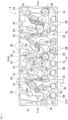
Fig. 3 is a plan view of a cylinder head. -
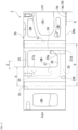
Fig. 4 is a cross-sectional view taken along line Z-Z ofFig. 3 (transverse cross-sectional view showing an inter-bore corresponding part). -
Fig. 5 is a partially cutout perspective view showing an inter-bore corresponding part of the cylinder head as viewed obliquely from above. - Embodiments of a cylinder head structure according to the present invention will be described below with reference to the drawings regarding a case of an industrial diesel engine. Note that in an industrial diesel engine (hereinafter, abbreviated as engine) E, the side provided with a
cooling fan 10 is the front, the side provided with aflywheel 7 is the rear, the side provided with an intake port 30 [side provided with an intake manifold (not shown)] is the right, and an exhaust port 28 [side provided with an exhaust manifold (not shown)] is the left. InFig. 5 , avertical wall 27 is added in an imaginary line to a conventional structure. - As shown in
Fig. 1 , a straight-four (multicylinder) engine E has acylinder head 2 assembled on acylinder block 1, a head cover 3 assembled on thecylinder head 2, and anoil pan 4 assembled under thecylinder block 1. 5 denotes a crankshaft, 6 denotes a piston, 7 denotes a flywheel, 8 denotes a transmission belt, 9 denotes a water pump, 10 denotes a cooling fan, and 11 denotes a radiator. An upper portion of thecylinder block 1 is formed in acylinder portion 1A embedding thepiston 6. - Cooling water w in a cooling device of this engine E generally flows in the following order. That is, as shown in
Fig. 1 , thewater pump 9 → thecylinder portion 1A ofcylinder block 1 → thecylinder head 2 → athermostat 12 → anupper hose 13 → theradiator 11 → a lower hose 14 → thewater pump 9. There is also a route in which part of the cooling water w cools anoil cooler 16 from thecylinder head 2 through asupply passage 15 that is a dedicated route, and then returns to thewater pump 9 through anexhaust passage 17. - The cooling water w entering the
cylinder portion 1A from the front flows also upward for eachcylinder 1a while flowing rearward basically. Therefore, the cooling water w flows in upward from a cylindercooling water channel 1W, which is a water jacket of thecylinder portion 1A, into a headcooling water channel 2W, which is a water jacket of thecylinder head 2, and flows from the rear to the front (to thewater pump 9 of the front). - As shown in
Fig. 2(A) , between theadjacent cylinders cylinder portion 1A, alower coupling wall 18, amiddle coupling wall 19, and anupper coupling wall 20 that connect and integrate theadjacent cylinders cooling water channel 1W. The headcooling water channel 2W of thecylinder head 2 and the cylindercooling water channel 1W of thecylinder portion 1A communicate with each other at a plurality of locations on an outside site of eachcylinder 1a, and communicate with each other by twocommunication holes adjacent cylinders - As shown in
Figs. 1 and5 , the headcooling water channel 2W through which the cooling water w passes is internally formed in thecylinder head 2, and an inter-bore corresponding portion (also called "inter-cylinder portion") 2b positioned above between theadjacent cylinders cylinder head 2 is shown inFigs. 2(A) and4 . In an inter-borecorresponding portion 2b, an area between a pair of left andright insertion walls 24 having aninsertion hole 2c through which a fasteningbolt 23 passes, the area surrounded by a cylinderhead bottom wall 26 and a headupper wall 25, is formed in the headcooling water channel 2W. - A
bottom surface 26a of the cylinderhead bottom wall 26 is a surface placed on anupper surface 1b of thecylinder portion 1A via a gasket G, and the headupper wall 25 is an upper wall of a cylinder head on which the head cover 3 is placed. Note that 28 inFigs. 3 to 5 denotes an exhaust port, and the headcooling water channel 2W is formed also at each of its upper and lower areas and the right side of theright insertion wall 24. - That is, as shown in
Figs. 2 to 5 , thecylinder head 2 assembled on thecylinder block 1 by the plurality of fasteningbolts 23 is provided with theinsertion walls fastening bolts adjacent cylinders cylinder block 1, the headupper wall 25 coupling the upper end portions of the pair ofinsertion walls head bottom wall 26, the headcooling water channel 2W surrounded by the pair ofinsertion walls upper wall 25, and the cylinderhead bottom wall 26 is formed, and thevertical wall 27 in a state of spanning the headupper wall 25 and the cylinderhead bottom wall 26 and extending in a direction coupling the pair ofinsertion walls cooling water channel 2W is formed between the pair ofinsertion walls - As shown in
Figs. 2(A) ,3 , and4 , thevertical wall 27 is continuously connected to and integrated with the left end of the right (intake port side)insertion wall 24, and a position i in the left-right direction of a left end (end on the side not connected to the insertion wall 24) 27a of thevertical wall 27 is formed in a state of being present in a center region C between the pair ofinsertion walls right insertion walls 24 where the center-to-center distance between the left andright insertion walls 24 is D, but may include a range other than the above (such as a range of 30% to 70%). - Where the left-right width of the
vertical wall 27 is a length d between the center of theright insertion wall 24 and theleft end 27a, the length d of thevertical wall 27 is set to an interval between the pair ofinsertion walls Fig. 4 , it is advantageous to form areinforcing wall 29 extending left-right (in a direction connecting the pair ofinsertion walls 24 and 24) in an upward protrusion rib shape on the cylinderhead bottom wall 26 in the inter-borecorresponding portion 2b. - A left end portion of the reinforcing
wall 29 is continuous to theleft insertion wall 24 while rising obliquely upward, and a vertical hole water channel (cooling water channel in a hole shape) 21A is formed in an oblique reinforcingwall portion 29a [seeFigs. 2(A), 2(C) , and4 ]. The verticalhole water channel 21A is communicated with thecommunication hole 21 on the left side of thecylinder portion 1A across the gasket G, and the verticalhole water channel 21A and thecommunication hole 21 causes the cylindercooling water channel 1W and the headcooling water channel 2W to be communicated up and down. - As shown in
Figs. 2(A), 2(B) , and4 , the headcooling water channel 2W on the front (one) side of thevertical wall 27 and thebottom surface 26a immediately below, that is, immediately below thevertical wall 27 are communicated with each other by an obliquehole water channel 22A formed to extend forward and upward from thebottom surface 26a. That is, the obliquehole water channel 22A (cooling water channel in an oblique hole shape) spanning the headcooling water channel 2W on one side partitioned by thevertical wall 27 and the lower end of thevertical wall 27 or thebottom surface 26a of the cylinderhead bottom wall 26 on the other side is provided in the lower portion of thevertical wall 27. The cylindercooling water channel 1W and the headcooling water channel 2W are also communicated with each other up and down by the obliquehole water channel 22A and thecommunication hole 22 on the right side, which communicate with each other across the gasket G. - Conventionally, although illustration is omitted, the inter-bore
corresponding portion 2b of the cylinder head has a structure without thevertical wall 27 in order to widely ensure the headcooling water channel 2W (seeFig. 4 of Patent Document 1), which is disadvantageous in strength and rigidity, and has a tendency that the axial force due to the tightening of thefastening bolts 23 is less likely to be uniformly transmitted to the cylinderhead bottom wall 26. Therefore, it was also attempted to provide the cylinderhead bottom wall 26 with a rib wall (such as the reinforcing wall 29) protruding upward, but improvement in strength and rigidity was not sufficient, and there was a limit. - Therefore, in the present invention, the
vertical wall 27 in a state of spanning the headupper wall 25 and the cylinderhead bottom wall 26 and extending in a direction coupling the pair ofinsertion walls cooling water channel 2W is formed between the pair ofinsertion walls vertical wall 27, which is newly provided, greatly shortens the length between theinsertion walls 24 and 24 [the length (span) of the beam when the headupper wall 25 is analogized as a double cantilever beam extending left and right is greatly reduced], the strength and rigidity of the inter-borecorresponding portion 2b can be greatly improved. - That is, since the axial force of the
fastening bolts insertion walls vertical wall 27 in contact with a bolt seat surface, the axial force is transmitted to thecylinder head 2 as evenly as possible as compared with the conventional structure without thevertical wall 27. Therefore, the axial force guided between the pair offastening bolts cylinder portion 1A and thecylinder head 2 can be greatly improved. - In a configuration in which the
left end 27a of thevertical wall 27 integrated with theright insertion wall 24 is set in a state of being present in the center region C between the pair ofinsertion walls 24 and 24 (seeFig. 4 ), the interval between the pair ofinsertion walls corresponding portion 2b can be further improved. - Since the oblique
hole water channel 22A inclined forward or rearward is formed in the lower portion of thevertical wall 27, the lower side (bottom surface 26a) of thevertical wall 27 and the head coolingwater channel 2W on the front or rear side of thevertical wall 27 can be easily communicated with each other even though thevertical wall 27 is provided, and a smooth flow of the cooling water w can be obtained. On the side without thevertical wall 27 in the inter-borecorresponding portion 2b, the verticalhole water channel 21A causing the lower side (bottom surface 26a) of thevertical wall 27 and the head coolingwater channel 2W to communicate with each other is formed in the reinforcingwall portion 29a, and therefore it is elaborated not to cause a decrease in strength and rigidity due to the provision of the verticalhole water channel 21A. - Since the
vertical wall 27 is provided to be biased to the right side of the engine E, that is, the intake port side (intake manifold arrangement side), the exhaust port side where the temperature tends to be high is not provided with thevertical wall 27, and the cooling water w easily moves through the head coolingwater channel 2W in the front-rear direction (cylinder arrangement direction), and thus there is an advantage that heat can be efficiently absorbed from the exhaust side. -
- (1) The
vertical wall 27 may be provided close to the left side so as to be integrated with the left side (exhaust port side)insertion wall 24. (2) Thevertical wall 27 may be provided independently at the left and right center portion between the pair ofinsertion walls vertical wall 27 and each of the left andright insertion walls - (3) The oblique
hole water channel 22A may be formed as an oblique hole causing the head coolingwater channel 2W on the rear side of thevertical wall 27 and thebottom surface 26a on the front side of thevertical wall 27 to communicate with each other. (4) The reinforcingwall 29 having a rib shape is not depicted inFig. 2(A) but depicted inFig. 4 . The reinforcingwall 29 is not necessarily provided, but is preferably provided. -
- 1: Cylinder block
- 1a: Cylinder
- 2: Cylinder head
- 2W: Head cooling water channel
- 21A: Cooling water channel having hole shape
- 22A: Cooling water channel having oblique hole shape
- 23: Fastening bolt
- 24: Insertion wall
- 25: Head upper wall
- 26: Cylinder head bottom wall
- 26a: Bottom surface
- 27: Vertical wall
- 27a: End
- 29a: Reinforcing wall portion
Claims (6)
- A cylinder head structure,wherein a cylinder head assembled on a cylinder block by a plurality of fastening bolts is provided with an insertion wall through which the fastening bolts arranged on both sides between adjacent cylinders in the cylinder block pass, a head upper wall coupling upper end portions of a pair of insertion walls, and a cylinder head bottom wall,a head cooling water channel surrounded by the pair of insertion walls, the head upper wall, and the cylinder head bottom wall is formed, anda vertical wall in a state of spanning the head upper wall and the cylinder head bottom wall and extending in a direction coupling the pair of insertion walls to block the head cooling water channel is formed between the pair of insertion walls.
- The cylinder head structure according to claim 1, wherein the vertical wall is formed in a state of being present in a center region between the pair of insertion walls.
- The cylinder head structure according to claim 1, wherein the vertical wall is connected to and integrated with any one of the pair of insertion walls.
- The cylinder head structure according to claim 3, wherein an end of the vertical wall on a side not connected to the insertion wall is formed in a state of being present in a center region between the pair of insertion walls.
- The cylinder head structure according to any one of claims 1 to 4, wherein a cooling water channel having an oblique hole shape spanning a head cooling water channel on one side partitioned by the vertical wall and a bottom surface of the cylinder head bottom wall immediately below the vertical wall or on an other side is provided in a lower portion of the vertical wall.
- The cylinder head structure according to any one of claims 1 to 4, wherein a reinforcing wall portion having an upward protrusion rib shape extending in a direction coupling the pair of insertion walls, and a cooling water channel having a hole shape penetrating the reinforcing wall portion up and down are formed on the cylinder head bottom wall.
Applications Claiming Priority (2)
| Application Number | Priority Date | Filing Date | Title |
|---|---|---|---|
| JP2022105562A JP7471346B2 (en) | 2022-06-30 | 2022-06-30 | Cylinder head structure |
| PCT/JP2023/013793 WO2024004308A1 (en) | 2022-06-30 | 2023-04-03 | Cylinder head structure |
Publications (2)
| Publication Number | Publication Date |
|---|---|
| EP4506555A1 true EP4506555A1 (en) | 2025-02-12 |
| EP4506555A4 EP4506555A4 (en) | 2026-04-15 |
Family
ID=89381973
Family Applications (1)
| Application Number | Title | Priority Date | Filing Date |
|---|---|---|---|
| EP23830762.3A Pending EP4506555A4 (en) | 2022-06-30 | 2023-04-03 | Cylinder head structure |
Country Status (5)
| Country | Link |
|---|---|
| US (1) | US12618356B2 (en) |
| EP (1) | EP4506555A4 (en) |
| JP (1) | JP7471346B2 (en) |
| CN (1) | CN119156491A (en) |
| WO (1) | WO2024004308A1 (en) |
Family Cites Families (15)
| Publication number | Priority date | Publication date | Assignee | Title |
|---|---|---|---|---|
| JPS56163731U (en) * | 1980-05-07 | 1981-12-04 | ||
| JPS6090957A (en) * | 1983-10-22 | 1985-05-22 | Mazda Motor Corp | Structure of cylinder head for engine |
| JPS60192857A (en) * | 1984-03-15 | 1985-10-01 | Mazda Motor Corp | Cylinder head structure of engine |
| JPH0224931Y2 (en) * | 1985-06-12 | 1990-07-09 | ||
| JPS62117255U (en) * | 1986-01-20 | 1987-07-25 | ||
| JPS63171643U (en) * | 1987-04-28 | 1988-11-08 | ||
| CA1337039C (en) * | 1988-08-23 | 1995-09-19 | Tsuneo Konno | Cooling system for multi-cylinder engine |
| JP4285900B2 (en) * | 2000-10-25 | 2009-06-24 | ヤンマー株式会社 | Cylinder head structure of internal combustion engine |
| JP3924446B2 (en) | 2001-09-25 | 2007-06-06 | 株式会社クボタ | Vertical multi-cylinder engine |
| JP2005155600A (en) * | 2003-10-31 | 2005-06-16 | Toyota Motor Corp | Water-cooled engine and its cylinder block |
| JP4788236B2 (en) * | 2005-08-19 | 2011-10-05 | トヨタ自動車株式会社 | Cylinder head cooling structure |
| JP4795905B2 (en) * | 2006-09-20 | 2011-10-19 | ヤマハ発動機株式会社 | Water-cooled engine |
| JP2009293575A (en) * | 2008-06-09 | 2009-12-17 | Nissan Motor Co Ltd | Oil passage structure and cylinder head for internal combustion engine |
| JP6036668B2 (en) | 2013-12-05 | 2016-11-30 | マツダ株式会社 | Multi-cylinder engine cooling structure |
| EP3214295A4 (en) * | 2014-10-27 | 2018-09-19 | Aichi Machine Industry Co., Ltd. | Cylinder head and internal combustion engine equipped with same |
-
2022
- 2022-06-30 JP JP2022105562A patent/JP7471346B2/en active Active
-
2023
- 2023-04-03 EP EP23830762.3A patent/EP4506555A4/en active Pending
- 2023-04-03 WO PCT/JP2023/013793 patent/WO2024004308A1/en not_active Ceased
- 2023-04-03 US US18/863,468 patent/US12618356B2/en active Active
- 2023-04-03 CN CN202380038514.3A patent/CN119156491A/en active Pending
Also Published As
| Publication number | Publication date |
|---|---|
| JP7471346B2 (en) | 2024-04-19 |
| WO2024004308A1 (en) | 2024-01-04 |
| JP2024005397A (en) | 2024-01-17 |
| CN119156491A (en) | 2024-12-17 |
| US20250314192A1 (en) | 2025-10-09 |
| EP4506555A4 (en) | 2026-04-15 |
| US12618356B2 (en) | 2026-05-05 |
Similar Documents
| Publication | Publication Date | Title |
|---|---|---|
| US6481392B1 (en) | Internal combustion engine | |
| US8555825B2 (en) | Cooling system defined in a cylinder block of an internal combustion engine | |
| US6729272B2 (en) | Cylinder head cooling construction for an internal combustion engine | |
| US20100132639A1 (en) | Liquid-cooled internal combustion | |
| CN108252816B (en) | Cooling structure of water-cooled engine | |
| JP6384492B2 (en) | Multi-cylinder engine cooling structure | |
| JP3503200B2 (en) | Cylinder block for multi-cylinder internal combustion engine | |
| US7044089B2 (en) | Cylinder head structure of engine | |
| US12618356B2 (en) | Cylinder head structure | |
| JP2000345838A (en) | Water-cooled internal combustion engine cooling system | |
| US7044088B2 (en) | Multi-cylinder engine and a method for alternatively producing multi-cylinder engines | |
| KR100341067B1 (en) | Internal Combustion Engine with Two Rows of Cylinders | |
| US7100545B2 (en) | Cylinder head for a water-cooled internal combustion piston engine having inner reinforcement | |
| JP2019027378A (en) | Cylinder head of internal combustion engine | |
| CN109026322B (en) | Cooling oil passage structure of engine | |
| CN107850001B (en) | Cooling structure of cylinder head | |
| JP4791304B2 (en) | Water-cooled engine | |
| JP2024005398A (en) | Engine bore structure | |
| JP6712947B2 (en) | Water cooling engine cooling structure | |
| EP3865687B1 (en) | Internal combustion engine with top-down cooling | |
| JP2514165Y2 (en) | Engine cylinder block | |
| CN109026321B (en) | Cooling oil passage structure of engine | |
| JP2022145262A (en) | Multicylinder internal combustion engine | |
| JP3071546B2 (en) | Engine cooling system | |
| JPH06346784A (en) | Cylinder cooling structure for two-cycle engine |
Legal Events
| Date | Code | Title | Description |
|---|---|---|---|
| STAA | Information on the status of an ep patent application or granted ep patent |
Free format text: STATUS: THE INTERNATIONAL PUBLICATION HAS BEEN MADE |
|
| PUAI | Public reference made under article 153(3) epc to a published international application that has entered the european phase |
Free format text: ORIGINAL CODE: 0009012 |
|
| STAA | Information on the status of an ep patent application or granted ep patent |
Free format text: STATUS: REQUEST FOR EXAMINATION WAS MADE |
|
| 17P | Request for examination filed |
Effective date: 20241107 |
|
| AK | Designated contracting states |
Kind code of ref document: A1 Designated state(s): AL AT BE BG CH CY CZ DE DK EE ES FI FR GB GR HR HU IE IS IT LI LT LU LV MC ME MK MT NL NO PL PT RO RS SE SI SK SM TR |
|
| DAV | Request for validation of the european patent (deleted) | ||
| DAX | Request for extension of the european patent (deleted) | ||
| A4 | Supplementary search report drawn up and despatched |
Effective date: 20260318 |
|
| RIC1 | Information provided on ipc code assigned before grant |
Ipc: F02F 1/24 20060101AFI20260312BHEP Ipc: F02F 1/36 20060101ALI20260312BHEP |