EP4506525A1 - Sensor assembly having a spring element and ratio of movement - Google Patents
Sensor assembly having a spring element and ratio of movement Download PDFInfo
- Publication number
- EP4506525A1 EP4506525A1 EP23190584.5A EP23190584A EP4506525A1 EP 4506525 A1 EP4506525 A1 EP 4506525A1 EP 23190584 A EP23190584 A EP 23190584A EP 4506525 A1 EP4506525 A1 EP 4506525A1
- Authority
- EP
- European Patent Office
- Prior art keywords
- trigger
- housing element
- housing
- deformation
- movement
- Prior art date
- Legal status (The legal status is an assumption and is not a legal conclusion. Google has not performed a legal analysis and makes no representation as to the accuracy of the status listed.)
- Granted
Links
Images

Classifications
-
- E—FIXED CONSTRUCTIONS
- E05—LOCKS; KEYS; WINDOW OR DOOR FITTINGS; SAFES
- E05B—LOCKS; ACCESSORIES THEREFOR; HANDCUFFS
- E05B81/00—Power-actuated vehicle locks
- E05B81/54—Electrical circuits
- E05B81/64—Monitoring or sensing, e.g. by using switches or sensors
- E05B81/76—Detection of handle operation; Detection of a user approaching a handle; Electrical switching actions performed by door handles
-
- E—FIXED CONSTRUCTIONS
- E05—LOCKS; KEYS; WINDOW OR DOOR FITTINGS; SAFES
- E05B—LOCKS; ACCESSORIES THEREFOR; HANDCUFFS
- E05B83/00—Vehicle locks specially adapted for particular types of wing or vehicle
- E05B83/16—Locks for luggage compartments, car boot lids or car bonnets
- E05B83/18—Locks for luggage compartments, car boot lids or car bonnets for car boot lids or rear luggage compartments
-
- E—FIXED CONSTRUCTIONS
- E05—LOCKS; KEYS; WINDOW OR DOOR FITTINGS; SAFES
- E05B—LOCKS; ACCESSORIES THEREFOR; HANDCUFFS
- E05B85/00—Details of vehicle locks not provided for in groups E05B77/00 - E05B83/00
- E05B85/10—Handles
-
- F—MECHANICAL ENGINEERING; LIGHTING; HEATING; WEAPONS; BLASTING
- F16—ENGINEERING ELEMENTS AND UNITS; GENERAL MEASURES FOR PRODUCING AND MAINTAINING EFFECTIVE FUNCTIONING OF MACHINES OR INSTALLATIONS; THERMAL INSULATION IN GENERAL
- F16F—SPRINGS; SHOCK-ABSORBERS; MEANS FOR DAMPING VIBRATION
- F16F1/00—Springs
- F16F1/02—Springs made of steel or other material having low internal friction; Wound, torsion, leaf, cup, ring or the like springs, the material of the spring not being relevant
- F16F1/025—Springs made of steel or other material having low internal friction; Wound, torsion, leaf, cup, ring or the like springs, the material of the spring not being relevant characterised by having a particular shape
- F16F1/027—Planar, e.g. in sheet form; leaf springs
-
- G—PHYSICS
- G05—CONTROLLING; REGULATING
- G05G—CONTROL DEVICES OR SYSTEMS INSOFAR AS CHARACTERISED BY MECHANICAL FEATURES ONLY
- G05G1/00—Controlling members, e.g. knobs or handles; Assemblies or arrangements thereof; Indicating position of controlling members
- G05G1/02—Controlling members for hand actuation by linear movement, e.g. push buttons
-
- E—FIXED CONSTRUCTIONS
- E05—LOCKS; KEYS; WINDOW OR DOOR FITTINGS; SAFES
- E05B—LOCKS; ACCESSORIES THEREFOR; HANDCUFFS
- E05B15/00—Other details of locks; Parts for engagement by bolts of fastening devices
- E05B15/04—Spring arrangements in locks
- E05B2015/0444—Springs additionally fulfilling an electric function
Definitions
- the invention relates generally to a sensor assembly used for actuating a latch release mechanism of an access panel of a vehicle, where the access panel may be any type of door, liftgate, tailgate or the like.
- Tailgates and liftgates, or any other type of access panel, for vehicles typically have a button or actuation device which opens the tailgate or liftgate.
- a button or actuation device which opens the tailgate or liftgate.
- One type of commonly used button or actuation device is a "microbutton,” or “microswitch,” where the microbutton is integrated into the brand logo or badge on the vehicle.
- a sensor assembly which may be integrated into the logo or badge of a vehicle, where the sensor assembly is used to actuate a latch release mechanism of an access panel of a vehicle, where minimal movement of the logo or badge is required to actuate the latch release mechanism.
- actuation device configured to electrically open a tailgate of a vehicle is DE 10 2021 004 934 , titled “Vehicle Door Operator.”
- actuation device configured to electrically open a tailgate of a vehicle is CN 106 097 485 , titled "The User Can Actuate The Vehicle Opening And Closing Control Device.”
- KR 2014-029586 Another example of an actuation device configured to electrically open a tailgate of a vehicle is KR 2014-029586 , titled “Tailgate Switch Assembly Having Logo For Vehicle.”
- actuation device configured to electrically open a tailgate of a vehicle is KR 2015-027317 , titled “Vehicle Trunk Open Switch Device.”
- the access panel may be a door, a liftgate, a tailgate, or any other type of structure that may be opened and closed.
- the present invention is a sensor assembly which is used for actuating a latch release mechanism of an access panel of a vehicle.
- the sensor assembly includes a cover portion which is integrated into the logo or badge of the vehicle. A force is applied to the cover portion when the cover portion is pressed by a driver or passenger, which causes deflection of a spring element.
- the spring element is shaped such that movement of the spring element is a multiple or ratio of the movement of the cover portion.
- the movement of the spring element is detected by a sensing element, and when a required amount of movement of the spring element is detected, the sensor sends a signal to actuate a latch release mechanism.
- the spring element is a separate component from the cover portion and the sensing element.
- the present invention is a trigger device for triggering an opening mechanism configured to open a flap of a vehicle, preferably a trunk of the vehicle, where the trigger device includes a housing assembly delimiting an inner space and including a first housing element movably mounted to a second housing element, the second housing element configured to be mounted to the flap of the vehicle, and the first housing element being relatively movable with respect to the second housing element between a non-triggering position and a triggering position along a trigger axis.
- a sensor device is arranged within the inner space and configured to detect a predetermined movement of the first housing element from the non-triggering position into the triggering position, the sensor device including a trigger element and a sensing element mounted to the second housing element, the sensing element being configured to detect movement of the trigger element.
- At least one deformation limiting element is connected to the trigger element and configured to limit the deformation of the trigger element in a direction substantially perpendicular to the trigger axis.
- the trigger element includes at least one deformation portion configured to be elastically deformed when the first housing element applies force to the trigger element, and at least one detection portion, where the movement of the detection portion is detected by the sensing element.
- the deformation limiting element and the deformation portion are configured to increase the movement of the detection portion when force is applied to the first housing element to move the first housing element between the non-triggering position and the triggering position.
- the deformation portion includes at least one outer flange portion, the outer flange portion connected to the deformation limiting element, at least one outer leg portion integrally formed with the outer flange portion, at least one inner leg portion integrally formed with the outer leg portion.
- the inner leg portion is integrally formed with the detection portion.
- the trigger element includes at least one support flange integrally formed with the detection portion, and the support flange secures the trigger element to the second housing element.
- the trigger element includes at least one contact area, and the first housing element is in contact with the contact area.
- the deformation limiting element is integrally formed with the second housing element.
- the present invention is a method for using a trigger device for triggering an opening mechanism configured to open a flap of a vehicle, preferably a trunk of the vehicle, where the method includes the steps of providing a housing assembly delimiting an inner space and including a first housing element movably mounted to a second housing element, the second housing element configured to be mounted to the flap of the vehicle, and the first housing element being relatively movable with respect to the second housing element between a non-triggering position and a triggering position along a trigger axis.
- the method also includes providing a sensor device arranged within the inner space, the sensor device including a trigger element and a sensing element mounted to the second housing element, providing at least one deformation limiting element connected to the trigger element, providing at least one deformation portion being part of the trigger element, and providing at least one detection portion being part of the trigger element.
- the method includes detecting a predetermined movement of the first housing element from the non-triggering position into the triggering position using the sensor device, detecting movement of the trigger element using the sensing element.
- the method includes limiting the deformation of the trigger element in a direction substantially perpendicular to the trigger axis using the deformation limiting element.
- the method includes elastically deforming the deformation portion when the first housing element applies force to the trigger element.
- the method includes detecting the movement of the detection portion using the sensing element, and the deformation limiting element and the deformation portion are configured to increase the movement of the detection portion when force is applied to the first housing element to move the first housing element between the non-triggering position and the triggering position.
- the trigger device 10 and latch release mechanism may be used to open any type of access panel, such as a door, liftgate, or tailgate.
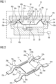
- the trigger device 10 includes a housing assembly 10a delimiting an inner space, shown generally at 10b, where the housing assembly 10a includes a first housing element 12, and the first housing element 12 may be integrated as part of the logo or badge of a vehicle.
- a sensor device, shown generally at 10d, is arranged within the inner space 10b.
- the sensor device 10d includes a trigger element, or spring element, shown generally at 14, and the first housing element 12 is in contact with the trigger element 14.
- the trigger element 14 includes a detection portion, or central flange 16, and integrally formed with the detection portion 16 is a plurality of deformation portions, or leg portions 18a, 18b, 18c, 18d.
- the first deformation portion 18a and third deformation portion 18c are connected to a deformation limiting element, or first wall 20a, and the second deformation portion 18b and fourth deformation portion 18d are connected to a second deformation limiting element 20b.
- each deformation portion 18a, 18b, 18c, 18d includes a corresponding outer flange portion 22a,22b,22c,22d, an outer leg portion 24a,24b,24c,24d, and an inner leg portion 26a,26b,26c,26d.
- Each outer flange portion 22a,22b,22c,22d is integrally formed with a corresponding outer leg portion 24a,24b,24c,24d
- each outer leg portion 24a,24b,24c,24d is integrally formed with a corresponding inner leg portion 26a,26b,26c,26d.
- Each inner leg portion 26a,26b,26c,26d is integrally formed with the detection portion 16.
- Each deformation portion 18a,18b,18c,18d has a contact area, each of which is shown generally at 28a,28b,28c,28d, which is in contact with the bottom surface of the first housing element 12.
- the housing assembly 10a of the trigger device 10 also includes a second housing element 30, which also delimits the inner space 10b, and the sensor device 10d also includes a sensing element 32. Mounted in the second housing element 30 is the sensing element 32.
- the deformation limiting elements 20a,20b may be part of the second housing element 30, as shown in Figs. 1 and 3 , or the deformation limiting elements 20a,20b may be part of a separate housing.
- the sensing element 32 is able to detect movement of the detection portion 16 of the trigger element 14. Referring to Figs. 1 and 3 , the first housing element 12 and the trigger element 14 are in a first position or non-triggering position.
- the same force is also applied to the trigger element 14, causing the trigger element 14 to deflect.
- the force from the first housing element 12 is applied to the contact areas 28a,28b,28c,28d of the deformation portions 18a, 18b,18c, 18d.
- the first housing element 12 moves in the direction of the arrow 36 along a trigger axis 10c, and the detection portion 16 also moves in the direction of the arrow 36 along the trigger axis 10c.
- the movement of the trigger element 14, or more specifically the deformation portions 18a, 18b, 18c, 18d is limited in a direction substantially perpendicular to the trigger axis 10c by the deformation limiting elements 20a,20b.
- the limitation of the movement of the deformation portions 18a, 18b, 18c, 18d in the direction substantially perpendicular to the trigger axis 10c and the shape of the deformation portions 18a, 18b, 18c, 18d is such that when the first housing element 12 moves a first distance 38a, the detection portion 16 moves a second distance 38b from the non-triggering position to a second position or triggering position, where the second distance 38b is greater than the first distance 38a. Additionally, the movement of the first housing element 12 in the direction of the arrow 36 along the trigger axis 10c is limited to the length of the first distance 38a. Integrally formed with the first housing element 12 is a first stopper 52 and a second stopper 54.
- Integrally formed with the deformation limiting element 20a is a first deformation limiting surface 56
- integrally formed with the second deformation limiting element 20b is a second deformation limiting surface 58.
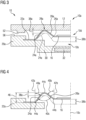
- the triggering position of the trigger element 14 is shown in Fig. 3 .
- An example of the movement of the first housing element 12 relative to the movement of the detection portion 16 is shown in Fig. 5 .
- the first distance 38a the first housing element 12 is moved is 1 mm
- the second distance 38b the detection portion 16 is moved is 2 mm.
- the shape of the deformation portions 18a,18b,18c,18d may be changed such that the detection portion 16 may move a greater or lesser distance 38b when the first distance 38a the first housing element 12 is moved is 1 mm. It is also within the scope of the invention that the relationship between the movement of the first housing element 12 relative to the movement of the detection portion 16 may be linear or non-linear. An example of the movement of the first housing element 12 and the relative movement of the detection portion 16 having a non-liner relationship is shown in the graph in Fig. 5 .
- outer flange portions 22a,22b,22c,22d, the outer leg portions 24a,24b,24c,24d, and the inner leg portion 26a,26b,26c,26d are positioned at various angles relative to one another, and to the detection portion 16.
- the first outer leg potion 24a is located at a first angle 40a relative to a vertical reference line 42a, where the vertical reference line 42a intersects an inflection point 44a between the outer flange portion 22a and the first outer leg potion 24a.
- the first inner leg portion 26a is located at a second angle 40b relative to another vertical reference line 42b, where the vertical reference line 42b intersects an inflection point 44b between the first inner leg portion 26a and the detection portion 16.
- the first outer leg portion 24a and the first inner leg portion 26a are positioned at a third angle 40c relative to one another, and the vertex 44c between the first outer leg portion 24a and the first inner leg portion 26a also corresponds to the contact area 28a of the first deformation portion 18a.
- the angles 40a,40b,40c also change as well when the position of the first housing element 12 and trigger element 14 change.
- the detection portion 16 has moved the second distance 38b
- the first angle 40a and the third angle 40c have increased
- the second angle 40b has decreased.
- FIG. 6 shows the ratio of the second angle 40b divided by the first angle 40a, and this ratio increases as the first housing element 12 is moved the after the application of the force 34. Because of the shape of the trigger element 14, the correlation between the ratio of the second angle 40b divided by the first angle 40a and the movement of the first housing element 12 is non-linear, as shown in Fig. 6 .
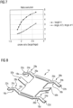
- FIG. 7 another graph is shown which includes the change in the overall height 46 of the trigger element 14 and the change in the ratio of the second angle 40b divided by the first angle 40a.
- Fig. 7 also shows the combination of the non-linear relationship between the displacements of the first housing element 12 and the detection portion 16.
- the other deformation portions 18b,18c,18d are similarly shaped, and therefore the outer flange portions 22b,22c,22d, the outer leg portions 24b,24c,24d, and the inner leg portion 26b,26c,26d are positioned similarly relative to one another, and the movement of the other deformation portions 18b, 18c, 18d is similar to that of the first deformation portion 18a as described above.
- the sensing element 32 is able to detect the distance 38b the detection portion 16 has been moved. Once the sensor 32 has detected that the detection portion 16 has been moved the distance 38b, the sensing element 32 sends a signal to actuate a latch release mechanism 48 to open the tailgate or liftgate of the vehicle.
- the ratio by which the detection portion 16 moves relative to the first housing element 12 is determined by the shape of the deformation portions 18a, 18b,18c, 18d.
- the ratio may be changed by changing the shape of one or more of the outer flange portion 22a,22b,22c,22d, the outer leg portion 24a,24b,24c,24d, and/or the inner leg portion 26a,26b,26c,26d.
- the ratio also may be changed by changing one or more of the angles 40a,40b,40c.
- the outer flange portions 22a,22b,22c,22d, the outer leg portions 24a,24b,24c,24d, the inner leg portions 26a,26b,26c,26d, and/or the deformation limiting elements 20a,20b may be variable in dimension, position, or thickness.
- the spring or material properties for each of these components may also be changed or varied to achieve desired ratios of movement of the deflection portion 16.
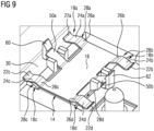
- FIG. 8 and 9 An alternate embodiment of the trigger element 14 according to the present invention is shown in Figs. 8 and 9 , with like numbers referring to like elements.
- a first support flange 50a and a second support flange 50b.
- Both support flanges 50a,50b are integrally formed with the detection portion 16, and are engaged with mounting brackets 60,62 formed as part of the second housing element 30.
- the support flanges 50a,50b ensure the radial position of the detection portion 16 in relation to the sensing element 32 after assembly.
- the support flanges 50a,50b also maintain the position of the trigger element 14 in place relative to the second housing element 30 during shipping.
- the first housing element 12 is part of a logo or badge of a vehicle, where the force 34 may be applied to any part of the first housing element 12 to result in the detection portion 16 moving the second distance 38b. Because the first distance 38a is less than the second distance 38b, the movement of the first housing element 12 may be minimized.
- the present invention is not limited to the embodiments described above.
- the shape and length of one or more of the outer flange portion 22a,22b,22c,22d, the outer leg portion 24a,24b,24c,24d, and/or the inner leg portion 26a,26b,26c,26d may be changed to effect the second distance 38b the detection portion 16 is moved as a result of the first housing element 12 being moved the first distance 38a.
- the present invention is a trigger device 10 for a latch release mechanism for a vehicle.
- the trigger device 10 includes a first housing element 12 in contact with a trigger element 14.
- the trigger element 14 is connected to a second housing element 30, and a sensing element 32 is mounted in the second housing element 30.
- a force 34 may be applied to the first housing element 12 to move the first housing element 12 a first distance 38a, which results in a detection portion 16 moving a second distance 38b.
- the sensing element 32 detects the movement of the detection portion 16. Once the detection portion 16 has moved the second distance 38b, the sensing element 32 sends a signal to actuate a latch release mechanism to open an access panel of a vehicle.
- the access panel may by any type of panel, such as, but not limited to, a door, tailgate, or liftgate.
- the trigger element 14 includes several deformation portions 18a,18b,18c,18d, where the shape of the deformation portions 18a,18b, 18c,18d may be changed, such that the distance 38b the detection portion 16 moves as a result of movement of the first housing element 12 may be increased or decreased.
Landscapes
- Engineering & Computer Science (AREA)
- General Engineering & Computer Science (AREA)
- Mechanical Engineering (AREA)
- Physics & Mathematics (AREA)
- General Physics & Mathematics (AREA)
- Automation & Control Theory (AREA)
- Lock And Its Accessories (AREA)
Abstract
Description
- The invention relates generally to a sensor assembly used for actuating a latch release mechanism of an access panel of a vehicle, where the access panel may be any type of door, liftgate, tailgate or the like.
- Tailgates and liftgates, or any other type of access panel, for vehicles typically have a button or actuation device which opens the tailgate or liftgate. One type of commonly used button or actuation device is a "microbutton," or "microswitch," where the microbutton is integrated into the brand logo or badge on the vehicle.
- Many current tailgate and liftgate designs incorporate the use of a microbutton or microswitch into the company logo on the vehicle, and the logo moves, or flexes, an undesirable amount. One proposed solution to this problem is to provide a flat button such that any part of the logo may be pressed to activate the mircobutton. However, the movement path on this type of sensor in insufficient for this solution to be effective.
- Accordingly, there exists a need for a sensor assembly which may be integrated into the logo or badge of a vehicle, where the sensor assembly is used to actuate a latch release mechanism of an access panel of a vehicle, where minimal movement of the logo or badge is required to actuate the latch release mechanism.
- An example of an actuation device configured to electrically open a tailgate of a vehicle is known in
US 2022/0336162 , titled "Actuation Device with Movable Switching Element, Vehicle and Method for Actuation." - Another example of an actuation device configured to electrically open a tailgate of a vehicle is
DE 10 2021 004 934 , titled "Vehicle Door Operator." - Another example of an actuation device configured to electrically open a tailgate of a vehicle is
CN 106 097 485 , titled "The User Can Actuate The Vehicle Opening And Closing Control Device." - Another example of an actuation device configured to electrically open a tailgate of a vehicle is
KR 2014-029586 - Another example of an actuation device configured to electrically open a tailgate of a vehicle is
KR 2015-027317 - Another example of an actuation device configured to electrically open a tailgate of a vehicle is
US 2022/0328261 , titled "Actuation Device, Vehicle And A Method For Actuation." - Therefore, it is an object of the present invention to provide a sensor assembly which is used for actuating a latch release mechanism of an access panel of a vehicle. The access panel may be a door, a liftgate, a tailgate, or any other type of structure that may be opened and closed.
- This object may be achieved by a sensor assembly according to
independent claims 1, and the method according to independent claim 6. Preferred embodiments are given in the dependent claims. - In an embodiment, the present invention is a sensor assembly which is used for actuating a latch release mechanism of an access panel of a vehicle. The sensor assembly includes a cover portion which is integrated into the logo or badge of the vehicle. A force is applied to the cover portion when the cover portion is pressed by a driver or passenger, which causes deflection of a spring element. The spring element is shaped such that movement of the spring element is a multiple or ratio of the movement of the cover portion. The movement of the spring element is detected by a sensing element, and when a required amount of movement of the spring element is detected, the sensor sends a signal to actuate a latch release mechanism. The spring element is a separate component from the cover portion and the sensing element.
- In an embodiment, the present invention is a trigger device for triggering an opening mechanism configured to open a flap of a vehicle, preferably a trunk of the vehicle, where the trigger device includes a housing assembly delimiting an inner space and including a first housing element movably mounted to a second housing element, the second housing element configured to be mounted to the flap of the vehicle, and the first housing element being relatively movable with respect to the second housing element between a non-triggering position and a triggering position along a trigger axis. A sensor device is arranged within the inner space and configured to detect a predetermined movement of the first housing element from the non-triggering position into the triggering position, the sensor device including a trigger element and a sensing element mounted to the second housing element, the sensing element being configured to detect movement of the trigger element. At least one deformation limiting element is connected to the trigger element and configured to limit the deformation of the trigger element in a direction substantially perpendicular to the trigger axis.
- In an embodiment, the trigger element includes at least one deformation portion configured to be elastically deformed when the first housing element applies force to the trigger element, and at least one detection portion, where the movement of the detection portion is detected by the sensing element.
- In an embodiment, the deformation limiting element and the deformation portion are configured to increase the movement of the detection portion when force is applied to the first housing element to move the first housing element between the non-triggering position and the triggering position.
- In an embodiment, the deformation portion includes at least one outer flange portion, the outer flange portion connected to the deformation limiting element, at least one outer leg portion integrally formed with the outer flange portion, at least one inner leg portion integrally formed with the outer leg portion. In an embodiment, the inner leg portion is integrally formed with the detection portion.
- In an embodiment, the trigger element includes at least one support flange integrally formed with the detection portion, and the support flange secures the trigger element to the second housing element.
- In an embodiment, the trigger element includes at least one contact area, and the first housing element is in contact with the contact area.
- In an embodiment, the deformation limiting element is integrally formed with the second housing element.
- In an embodiment, the present invention is a method for using a trigger device for triggering an opening mechanism configured to open a flap of a vehicle, preferably a trunk of the vehicle, where the method includes the steps of providing a housing assembly delimiting an inner space and including a first housing element movably mounted to a second housing element, the second housing element configured to be mounted to the flap of the vehicle, and the first housing element being relatively movable with respect to the second housing element between a non-triggering position and a triggering position along a trigger axis. The method also includes providing a sensor device arranged within the inner space, the sensor device including a trigger element and a sensing element mounted to the second housing element, providing at least one deformation limiting element connected to the trigger element, providing at least one deformation portion being part of the trigger element, and providing at least one detection portion being part of the trigger element.
- In an embodiment, the method includes detecting a predetermined movement of the first housing element from the non-triggering position into the triggering position using the sensor device, detecting movement of the trigger element using the sensing element.
- In an embodiment, the method includes limiting the deformation of the trigger element in a direction substantially perpendicular to the trigger axis using the deformation limiting element.
- In an embodiment, the method includes elastically deforming the deformation portion when the first housing element applies force to the trigger element.
- In an embodiment, the method includes detecting the movement of the detection portion using the sensing element, and the deformation limiting element and the deformation portion are configured to increase the movement of the detection portion when force is applied to the first housing element to move the first housing element between the non-triggering position and the triggering position.
- Further areas of applicability of the present invention will become apparent from the detailed description provided hereinafter. It should be understood that the detailed description and specific examples, while indicating the preferred embodiment of the invention, are intended for purposes of illustration only and are not intended to limit the scope of the invention.
- The present invention will become more fully understood from the detailed description and the accompanying drawings, wherein:
- Fig. 1
- is a diagram of a sensor assembly which is used for actuating a latch release mechanism, according to embodiments of the present invention;
- Fig. 2
- is a perspective view of a spring element which is part of a sensor assembly used for actuating a latch release mechanism, according to embodiments of the present invention;
- Fig. 3
- is an enlarged view of the area surrounded by the dashed line in
Fig. 1 ; - Fig. 4
- is an enlarged view of the area surrounded by the dashed line in
Fig. 1 , with the cover portion removed; - Fig. 5
- is a graph representing the movement of a cover portion relative to the movement of a central flange, the central flange being part of a spring element, and the cover portion and central flange are part of a sensor assembly used for actuating a latch release mechanism, according to embodiments of the present invention;
- Fig. 6
- is graph representing the correlation between the movement of a cover portion and the ratio of the angles of two parts of a leg portion, where the leg portion is part of a spring element, and the cover portion and spring element are part of a sensor assembly used for actuating a latch release mechanism, according to embodiments of the present invention;
- Fig. 7
- is a graph representing the change in the overall height of a spring element and the change in the ratio of the angles of two parts of a leg portion, where the leg portion is part of a spring element, and the spring element is part of a sensor assembly used for actuating a latch release mechanism, according to embodiments of the present invention;
- Fig. 8
- is a perspective view of an alternate embodiment of a spring element which is part of a sensor assembly used for actuating a latch release mechanism, according to embodiments of the present invention; and
- Fig. 9
- is a perspective view of an alternate embodiment of a spring element connected to a second housing element, where the spring element is part of a sensor assembly used for actuating a latch release mechanism, according to embodiments of the present invention.
- The following description of the preferred embodiment(s) is merely exemplary in nature and is in no way intended to limit the invention, its application, or uses.
- Referring to
Fig. 1 , an embodiment of a trigger device used for actuating a latch release mechanism for a vehicle is shown generally at 10. Thetrigger device 10 and latch release mechanism may be used to open any type of access panel, such as a door, liftgate, or tailgate. Thetrigger device 10 includes ahousing assembly 10a delimiting an inner space, shown generally at 10b, where thehousing assembly 10a includes afirst housing element 12, and thefirst housing element 12 may be integrated as part of the logo or badge of a vehicle. A sensor device, shown generally at 10d, is arranged within theinner space 10b. Thesensor device 10d includes a trigger element, or spring element, shown generally at 14, and thefirst housing element 12 is in contact with thetrigger element 14. Thetrigger element 14 includes a detection portion, orcentral flange 16, and integrally formed with thedetection portion 16 is a plurality of deformation portions, orleg portions first deformation portion 18a andthird deformation portion 18c are connected to a deformation limiting element, orfirst wall 20a, and thesecond deformation portion 18b andfourth deformation portion 18d are connected to a seconddeformation limiting element 20b. - More specifically, each
deformation portion outer flange portion outer leg portion inner leg portion outer flange portion outer leg portion outer leg portion inner leg portion inner leg portion detection portion 16. Eachdeformation portion first housing element 12. - The
housing assembly 10a of thetrigger device 10 also includes asecond housing element 30, which also delimits theinner space 10b, and thesensor device 10d also includes asensing element 32. Mounted in thesecond housing element 30 is thesensing element 32. Thedeformation limiting elements second housing element 30, as shown inFigs. 1 and3 , or thedeformation limiting elements sensing element 32 is able to detect movement of thedetection portion 16 of thetrigger element 14. Referring toFigs. 1 and3 , thefirst housing element 12 and thetrigger element 14 are in a first position or non-triggering position. When a force, indicated by thearrow 34, is applied to thefirst housing element 12, the same force is also applied to thetrigger element 14, causing thetrigger element 14 to deflect. The force from thefirst housing element 12 is applied to thecontact areas deformation portions first housing element 12 moves in the direction of thearrow 36 along atrigger axis 10c, and thedetection portion 16 also moves in the direction of thearrow 36 along thetrigger axis 10c. The movement of thetrigger element 14, or more specifically thedeformation portions trigger axis 10c by thedeformation limiting elements deformation portions trigger axis 10c and the shape of thedeformation portions first housing element 12 moves afirst distance 38a, thedetection portion 16 moves asecond distance 38b from the non-triggering position to a second position or triggering position, where thesecond distance 38b is greater than thefirst distance 38a. Additionally, the movement of thefirst housing element 12 in the direction of thearrow 36 along thetrigger axis 10c is limited to the length of thefirst distance 38a. Integrally formed with thefirst housing element 12 is afirst stopper 52 and asecond stopper 54. Integrally formed with thedeformation limiting element 20a is a firstdeformation limiting surface 56, and integrally formed with the seconddeformation limiting element 20b is a seconddeformation limiting surface 58. When thefirst housing element 12 is moved to the triggering position, thefirst stopper 52 is in contact with the firstdeformation limiting surface 56, and thesecond stopper 54 is in contact with the seconddeformation limiting surface 58. The limitation of movement of thefirst housing element 12 and thetrigger element 14 prevents damage to thefirst housing element 12 and thetrigger element 14 as a result of excessive force applied to thefirst housing element 12 during operation. - The triggering position of the
trigger element 14 is shown inFig. 3 . An example of the movement of thefirst housing element 12 relative to the movement of thedetection portion 16 is shown inFig. 5 . For example, it is seen inFig. 5 when thefirst distance 38a thefirst housing element 12 is moved (in the direction of the arrow 36) is 1 mm, thesecond distance 38b thedetection portion 16 is moved is 2 mm. - However, it is within the scope of the invention that the shape of the
deformation portions detection portion 16 may move a greater orlesser distance 38b when thefirst distance 38a thefirst housing element 12 is moved is 1 mm. It is also within the scope of the invention that the relationship between the movement of thefirst housing element 12 relative to the movement of thedetection portion 16 may be linear or non-linear. An example of the movement of thefirst housing element 12 and the relative movement of thedetection portion 16 having a non-liner relationship is shown in the graph inFig. 5 . - It is also shown in
Figs. 1-3 that theouter flange portions outer leg portions inner leg portion detection portion 16. - For example, with regard to the
first deformation portion 18a, the firstouter leg potion 24a is located at afirst angle 40a relative to avertical reference line 42a, where thevertical reference line 42a intersects aninflection point 44a between theouter flange portion 22a and the firstouter leg potion 24a. The firstinner leg portion 26a is located at asecond angle 40b relative to anothervertical reference line 42b, where thevertical reference line 42b intersects aninflection point 44b between the firstinner leg portion 26a and thedetection portion 16. The firstouter leg portion 24a and the firstinner leg portion 26a are positioned at athird angle 40c relative to one another, and thevertex 44c between the firstouter leg portion 24a and the firstinner leg portion 26a also corresponds to thecontact area 28a of thefirst deformation portion 18a. - Because the
outer flange portion 22a, theouter leg portion 24a, and theinner leg portion 26a all move as a result of theforce 34 being applied to thefirst housing element 12, theangles first housing element 12 andtrigger element 14 change. When thedetection portion 16 has moved thesecond distance 38b, thefirst angle 40a and thethird angle 40c have increased, and thesecond angle 40b has decreased. For example, referring to the graph shown inFig. 6 , the correlation between the movement of thefirst housing element 12 to the ratio of thefirst angle 40a to thesecond angle 40b is shown. The graph inFig. 6 shows the ratio of thesecond angle 40b divided by thefirst angle 40a, and this ratio increases as thefirst housing element 12 is moved the after the application of theforce 34. Because of the shape of thetrigger element 14, the correlation between the ratio of thesecond angle 40b divided by thefirst angle 40a and the movement of thefirst housing element 12 is non-linear, as shown inFig. 6 . - Referring now to
Fig. 7 , another graph is shown which includes the change in theoverall height 46 of thetrigger element 14 and the change in the ratio of thesecond angle 40b divided by thefirst angle 40a.Fig. 7 also shows the combination of the non-linear relationship between the displacements of thefirst housing element 12 and thedetection portion 16. - The
other deformation portions outer flange portions outer leg portions inner leg portion other deformation portions first deformation portion 18a as described above. - The
sensing element 32 is able to detect thedistance 38b thedetection portion 16 has been moved. Once thesensor 32 has detected that thedetection portion 16 has been moved thedistance 38b, thesensing element 32 sends a signal to actuate alatch release mechanism 48 to open the tailgate or liftgate of the vehicle. - The ratio by which the
detection portion 16 moves relative to thefirst housing element 12 is determined by the shape of thedeformation portions outer flange portion outer leg portion inner leg portion angles outer flange portions outer leg portions inner leg portions deformation limiting elements deflection portion 16. - An alternate embodiment of the
trigger element 14 according to the present invention is shown inFigs. 8 and9 , with like numbers referring to like elements. In the embodiment shown, there is afirst support flange 50a, and asecond support flange 50b. Bothsupport flanges detection portion 16, and are engaged with mountingbrackets second housing element 30. Thesupport flanges detection portion 16 in relation to thesensing element 32 after assembly. Thesupport flanges trigger element 14 in place relative to thesecond housing element 30 during shipping. - In an embodiment, the
first housing element 12 is part of a logo or badge of a vehicle, where theforce 34 may be applied to any part of thefirst housing element 12 to result in thedetection portion 16 moving thesecond distance 38b. Because thefirst distance 38a is less than thesecond distance 38b, the movement of thefirst housing element 12 may be minimized. - The present invention is not limited to the embodiments described above. In alternate embodiments, the shape and length of one or more of the
outer flange portion outer leg portion inner leg portion second distance 38b thedetection portion 16 is moved as a result of thefirst housing element 12 being moved thefirst distance 38a. In an embodiment, the present invention is atrigger device 10 for a latch release mechanism for a vehicle. Thetrigger device 10 includes afirst housing element 12 in contact with atrigger element 14. Thetrigger element 14 is connected to asecond housing element 30, and asensing element 32 is mounted in thesecond housing element 30. Aforce 34 may be applied to thefirst housing element 12 to move the first housing element 12 afirst distance 38a, which results in adetection portion 16 moving asecond distance 38b. Thesensing element 32 detects the movement of thedetection portion 16. Once thedetection portion 16 has moved thesecond distance 38b, thesensing element 32 sends a signal to actuate a latch release mechanism to open an access panel of a vehicle. The access panel may by any type of panel, such as, but not limited to, a door, tailgate, or liftgate. Thetrigger element 14 includesseveral deformation portions deformation portions distance 38b thedetection portion 16 moves as a result of movement of thefirst housing element 12 may be increased or decreased. - The description of the invention is merely exemplary in nature and, thus, variations that do not depart from the gist of the invention are intended to be within the scope of the invention. Such variations are not to be regarded as a departure from the spirit and scope of the invention.
Claims (6)
- A trigger device (10) for triggering an opening mechanism configured to open a flap of a vehicle, preferably a trunk of the vehicle, the trigger device (10) comprising:- a housing assembly (10a) delimiting an inner space (10b) and including a first housing element (12) movably mounted to a second housing element (30), the second housing element (30) configured to be mounted to the flap of the vehicle, and the first housing element (12) being relatively movable with respect to the second housing element (30) between a non-triggering position and a triggering position along a trigger axis (10c);- a sensor device (10d) arranged within the inner space (10b) and configured to detect a predetermined movement of the first housing element (12) from the non-triggering position into the triggering position, the sensor device (10d) including a trigger element (14) and a sensing element (32) mounted to the second housing element (30), the sensing element (32) being configured to detect movement of the trigger element (14); and- at least one deformation limiting element (20a,20b) connected to the trigger element (14) and configured to limit the deformation of the trigger element (14) in a direction substantially perpendicular to the trigger axis (10c);- wherein the trigger element (14) includes at least one deformation portion (18a,18b,18c,18d) configured to be elastically deformed when the first housing element (12) applies force to the trigger element (14), and at least one detection portion (16), where the movement of the at least one detection portion (16) is detected by the sensing element (32); andwherein the deformation limiting element (20a,20b) and the deformation portion (18a,18b) are configured to increase the movement of the detection portion (16) when force is applied to the first housing element (12) to move the first housing element (12) between the non-triggering position and the triggering position.
- The trigger device (10) of one of the preceding claims, the at least one deformation portion (18a,18b,18c,18d) further comprising:- at least one outer flange portion (22a,22b,22c,22d), the at least one outer flange portion (22a,22b,22c,22d) connected to the at least one deformation limiting element (20a,20b);- at least one outer leg portion (24a,24b,24c,24d) integrally formed with the at least one outer flange portion (22a,22b,22c,22d); and- at least one inner leg portion (26a,26b,26c,26d) integrally formed with the at least one outer leg portion (24a,24b,24c,24d);- wherein the at least one inner leg portion (26a,26b,26c,26d) is integrally formed with the at least one detection portion (16).
- The trigger device (10) of one of the preceding claims, the trigger element (14) further comprising:- at least one support flange (50a) integrally formed with the detection portion (16);- wherein the at least one support flange (50a) secures the trigger element (14) to the second housing element (30).
- The trigger device (10) of one of the preceding claims, the trigger element (14) further comprising:- at least one contact area (28a,28b,28c,28d);- wherein the first housing element (12) is in contact with the at least one contact area (28a,28b,28c,28d).
- The trigger device (10) of one of the preceding claims, further comprising wherein the at least one deformation limiting element (20a,20b) is integrally formed with the second housing element (30).
- A method for using a trigger device (10) for triggering an opening mechanism configured to open a flap of a vehicle, preferably a trunk of the vehicle, comprising the steps of:- providing a housing assembly (10a) delimiting an inner space (10b) and including a first housing element (12) movably mounted to a second housing element (30), the second housing element (30) configured to be mounted to the flap of the vehicle, and the first housing element (12) being relatively movable with respect to the second housing element (30) between a non-triggering position and a triggering position along a trigger axis (10c);- providing a sensor device (10d) arranged within the inner space (10b), the sensor device (10d) including a trigger element (14) and a sensing element (32) mounted to the second housing element (30);- providing at least one deformation limiting element (20a,20b) connected to the trigger element (14);- providing at least one deformation portion (18a, 18b, 18c, 18d) being part of the trigger element (14); and- providing at least one detection portion (16) being part of the trigger element (14);- detecting a predetermined movement of the first housing element (12) from the non-triggering position into the triggering position using the sensor device (10d);- detecting movement of the trigger element (14) using the sensing element (32);- limiting the deformation of the trigger element (14) in a direction substantially perpendicular to the trigger axis (10c) using the at least one deformation limiting element (20a,20b);- elastically deforming the at least one deformation portion (18a, 18b, 18c, 18d) when the first housing element (12) applies force to the trigger element (14);- detecting the movement of the at least one detection portion (16) using the sensing element (32), and the deformation limiting element (20a,20b) and the deformation portion (18a, 18b) are configured to increase the movement of the at least one detection portion (16) when force is applied to the first housing element (12) to move the first housing element (12) between the non-triggering position and the triggering position.
Priority Applications (1)
| Application Number | Priority Date | Filing Date | Title |
|---|---|---|---|
| EP23190584.5A EP4506525B1 (en) | 2023-08-09 | 2023-08-09 | Sensor assembly having a spring element and ratio of movement |
Applications Claiming Priority (1)
| Application Number | Priority Date | Filing Date | Title |
|---|---|---|---|
| EP23190584.5A EP4506525B1 (en) | 2023-08-09 | 2023-08-09 | Sensor assembly having a spring element and ratio of movement |
Publications (2)
| Publication Number | Publication Date |
|---|---|
| EP4506525A1 true EP4506525A1 (en) | 2025-02-12 |
| EP4506525B1 EP4506525B1 (en) | 2026-01-21 |
Family
ID=87567468
Family Applications (1)
| Application Number | Title | Priority Date | Filing Date |
|---|---|---|---|
| EP23190584.5A Active EP4506525B1 (en) | 2023-08-09 | 2023-08-09 | Sensor assembly having a spring element and ratio of movement |
Country Status (1)
| Country | Link |
|---|---|
| EP (1) | EP4506525B1 (en) |
Citations (10)
| Publication number | Priority date | Publication date | Assignee | Title |
|---|---|---|---|---|
| US4793601A (en) * | 1982-09-09 | 1988-12-27 | Alcatel N.V. | Key spring |
| EP1162332A1 (en) * | 2000-06-09 | 2001-12-12 | FIAT AUTO S.p.A. | Vehicle door handle |
| US20110013408A1 (en) * | 2008-03-27 | 2011-01-20 | Tyco Electronics Canada, Ulc | Combination light and switch assembly |
| KR20140029586A (en) | 2012-08-28 | 2014-03-11 | 주식회사 대동 | Tailgate switch assembly having logo for vehicels |
| WO2014131576A1 (en) * | 2013-03-01 | 2014-09-04 | Zf Friedrichshafen Ag | Pushbutton switch |
| KR20150027317A (en) | 2013-08-20 | 2015-03-12 | 현대자동차주식회사 | Trunk open switch device of vehicle |
| CN106097485A (en) | 2015-05-01 | 2016-11-09 | Adac塑模公司 | The vehicle open and close part that user can activate controls device |
| WO2020156812A1 (en) * | 2019-01-30 | 2020-08-06 | Bayerische Motoren Werke Aktiengesellschaft | Actuating device for an opening and closing device |
| DE102021004934A1 (en) | 2021-10-01 | 2021-12-16 | Daimler Ag | Vehicle door operator |
| US20220328261A1 (en) | 2019-09-05 | 2022-10-13 | Huf Hülsbeck & Fürst Gmbh & Co. Kg | Actuation Device, Vehicle and a Method for Actuation |
-
2023
- 2023-08-09 EP EP23190584.5A patent/EP4506525B1/en active Active
Patent Citations (11)
| Publication number | Priority date | Publication date | Assignee | Title |
|---|---|---|---|---|
| US4793601A (en) * | 1982-09-09 | 1988-12-27 | Alcatel N.V. | Key spring |
| EP1162332A1 (en) * | 2000-06-09 | 2001-12-12 | FIAT AUTO S.p.A. | Vehicle door handle |
| US20110013408A1 (en) * | 2008-03-27 | 2011-01-20 | Tyco Electronics Canada, Ulc | Combination light and switch assembly |
| KR20140029586A (en) | 2012-08-28 | 2014-03-11 | 주식회사 대동 | Tailgate switch assembly having logo for vehicels |
| WO2014131576A1 (en) * | 2013-03-01 | 2014-09-04 | Zf Friedrichshafen Ag | Pushbutton switch |
| KR20150027317A (en) | 2013-08-20 | 2015-03-12 | 현대자동차주식회사 | Trunk open switch device of vehicle |
| CN106097485A (en) | 2015-05-01 | 2016-11-09 | Adac塑模公司 | The vehicle open and close part that user can activate controls device |
| WO2020156812A1 (en) * | 2019-01-30 | 2020-08-06 | Bayerische Motoren Werke Aktiengesellschaft | Actuating device for an opening and closing device |
| US20220328261A1 (en) | 2019-09-05 | 2022-10-13 | Huf Hülsbeck & Fürst Gmbh & Co. Kg | Actuation Device, Vehicle and a Method for Actuation |
| US20220336162A1 (en) | 2019-09-05 | 2022-10-20 | Huf Hülsbeck & Fürst Gmbh & Co. Kg | Actuation Device with Movable Switching Element, Vehicle and Method for Actuation |
| DE102021004934A1 (en) | 2021-10-01 | 2021-12-16 | Daimler Ag | Vehicle door operator |
Also Published As
| Publication number | Publication date |
|---|---|
| EP4506525B1 (en) | 2026-01-21 |
Similar Documents
| Publication | Publication Date | Title |
|---|---|---|
| US12354813B2 (en) | Actuation device for mounting on a vehicle part, vehicle and method for actuation for triggering a vehicle function | |
| US7635151B2 (en) | Release handle with integrated inertia locking mechanism | |
| US11946295B2 (en) | Door handle arrangement | |
| EP2776651B1 (en) | Lock device having a multi-part pawl | |
| EP4025750B1 (en) | Actuation device with movable switch element, vehicle, and actuation method | |
| US6712409B2 (en) | External door handle for vehicles | |
| US5772062A (en) | Inlet tray of a car tank | |
| US20110012376A1 (en) | Lock unit having a slotted pawl | |
| US20210108450A1 (en) | Door leaf assembly with electric unlocking system | |
| US20090044449A1 (en) | Motor-operated component with anti-trapping means | |
| US20140084603A1 (en) | Deformation driven blocking mechanism for an automobile | |
| JP2009504498A (en) | Windshield wiper device | |
| US11505970B2 (en) | Door leaf handle for a motor vehicle | |
| EP4506525B1 (en) | Sensor assembly having a spring element and ratio of movement | |
| US20120318646A1 (en) | Switch for a belt lock | |
| EP1300534B1 (en) | Receptacle assembly with a case pivotally mounted in a housing shell | |
| JP2010112542A (en) | Cushion | |
| US10131283B2 (en) | Glove box bin bumper stops | |
| US9752368B2 (en) | Door checker device for use in automobiles | |
| US12473758B2 (en) | Decorative element with an actuation mode, vehicle element and vehicle | |
| US6512310B1 (en) | Electro-mechanical impact detecting device for vehicles | |
| US20240271469A1 (en) | Electronic sensor module and handle module | |
| WO1997025624A2 (en) | Mechanical shock sensor | |
| US7091433B2 (en) | Low profile automotive latch release switch assembly | |
| EP0361679B1 (en) | Tailgate latch |
Legal Events
| Date | Code | Title | Description |
|---|---|---|---|
| PUAI | Public reference made under article 153(3) epc to a published international application that has entered the european phase |
Free format text: ORIGINAL CODE: 0009012 |
|
| STAA | Information on the status of an ep patent application or granted ep patent |
Free format text: STATUS: THE APPLICATION HAS BEEN PUBLISHED |
|
| AK | Designated contracting states |
Kind code of ref document: A1 Designated state(s): AL AT BE BG CH CY CZ DE DK EE ES FI FR GB GR HR HU IE IS IT LI LT LU LV MC ME MK MT NL NO PL PT RO RS SE SI SK SM TR |
|
| RAP1 | Party data changed (applicant data changed or rights of an application transferred) |
Owner name: SCHAEFFLER TECHNOLOGIES AG & CO. KG |
|
| STAA | Information on the status of an ep patent application or granted ep patent |
Free format text: STATUS: REQUEST FOR EXAMINATION WAS MADE |
|
| 17P | Request for examination filed |
Effective date: 20250812 |
|
| GRAP | Despatch of communication of intention to grant a patent |
Free format text: ORIGINAL CODE: EPIDOSNIGR1 |
|
| STAA | Information on the status of an ep patent application or granted ep patent |
Free format text: STATUS: GRANT OF PATENT IS INTENDED |
|
| RIC1 | Information provided on ipc code assigned before grant |
Ipc: E05B 81/76 20140101AFI20250829BHEP Ipc: E05B 83/18 20140101ALI20250829BHEP Ipc: E05B 85/10 20140101ALI20250829BHEP Ipc: G05G 1/02 20060101ALI20250829BHEP Ipc: F16F 1/02 20060101ALI20250829BHEP Ipc: E05B 15/04 20060101ALN20250829BHEP |
|
| INTG | Intention to grant announced |
Effective date: 20251006 |
|
| GRAS | Grant fee paid |
Free format text: ORIGINAL CODE: EPIDOSNIGR3 |
|
| GRAA | (expected) grant |
Free format text: ORIGINAL CODE: 0009210 |
|
| STAA | Information on the status of an ep patent application or granted ep patent |
Free format text: STATUS: THE PATENT HAS BEEN GRANTED |
|
| AK | Designated contracting states |
Kind code of ref document: B1 Designated state(s): AL AT BE BG CH CY CZ DE DK EE ES FI FR GB GR HR HU IE IS IT LI LT LU LV MC ME MK MT NL NO PL PT RO RS SE SI SK SM TR |
|
| REG | Reference to a national code |
Ref country code: CH Ref legal event code: F10 Free format text: ST27 STATUS EVENT CODE: U-0-0-F10-F00 (AS PROVIDED BY THE NATIONAL OFFICE) Effective date: 20260121 |
|
| REG | Reference to a national code |
Ref country code: DE Ref legal event code: R096 Ref document number: 602023010951 Country of ref document: DE |
|
| REG | Reference to a national code |
Ref country code: IE Ref legal event code: FG4D |
|
| P01 | Opt-out of the competence of the unified patent court (upc) registered |
Free format text: CASE NUMBER: UPC_APP_0012146_4506525/2026 Effective date: 20260408 |
|
| P01 | Opt-out of the competence of the unified patent court (upc) registered |
Free format text: CASE NUMBER: UPC_APP_0012146_4506525/2026 Effective date: 20260408 |
|
| REG | Reference to a national code |
Ref country code: NL Ref legal event code: MP Effective date: 20260121 |
|
| PG25 | Lapsed in a contracting state [announced via postgrant information from national office to epo] |
Ref country code: NL Free format text: LAPSE BECAUSE OF FAILURE TO SUBMIT A TRANSLATION OF THE DESCRIPTION OR TO PAY THE FEE WITHIN THE PRESCRIBED TIME-LIMIT Effective date: 20260121 |
|
| REG | Reference to a national code |
Ref country code: AT Ref legal event code: MK05 Ref document number: 1878864 Country of ref document: AT Kind code of ref document: T Effective date: 20260121 |
|
| PG25 | Lapsed in a contracting state [announced via postgrant information from national office to epo] |
Ref country code: RS Free format text: LAPSE BECAUSE OF FAILURE TO SUBMIT A TRANSLATION OF THE DESCRIPTION OR TO PAY THE FEE WITHIN THE PRESCRIBED TIME-LIMIT Effective date: 20260421 |
|
| PG25 | Lapsed in a contracting state [announced via postgrant information from national office to epo] |
Ref country code: ES Free format text: LAPSE BECAUSE OF FAILURE TO SUBMIT A TRANSLATION OF THE DESCRIPTION OR TO PAY THE FEE WITHIN THE PRESCRIBED TIME-LIMIT Effective date: 20260121 |
|
| PG25 | Lapsed in a contracting state [announced via postgrant information from national office to epo] |
Ref country code: PL Free format text: LAPSE BECAUSE OF FAILURE TO SUBMIT A TRANSLATION OF THE DESCRIPTION OR TO PAY THE FEE WITHIN THE PRESCRIBED TIME-LIMIT Effective date: 20260121 |
|
| PG25 | Lapsed in a contracting state [announced via postgrant information from national office to epo] |
Ref country code: GR Free format text: LAPSE BECAUSE OF FAILURE TO SUBMIT A TRANSLATION OF THE DESCRIPTION OR TO PAY THE FEE WITHIN THE PRESCRIBED TIME-LIMIT Effective date: 20260422 |
|
| REG | Reference to a national code |
Ref country code: LT Ref legal event code: MG9D |
|
| PG25 | Lapsed in a contracting state [announced via postgrant information from national office to epo] |
Ref country code: LT Free format text: LAPSE BECAUSE OF FAILURE TO SUBMIT A TRANSLATION OF THE DESCRIPTION OR TO PAY THE FEE WITHIN THE PRESCRIBED TIME-LIMIT Effective date: 20260121 |
|
| PG25 | Lapsed in a contracting state [announced via postgrant information from national office to epo] |
Ref country code: NO Free format text: LAPSE BECAUSE OF FAILURE TO SUBMIT A TRANSLATION OF THE DESCRIPTION OR TO PAY THE FEE WITHIN THE PRESCRIBED TIME-LIMIT Effective date: 20260421 |
|
| PG25 | Lapsed in a contracting state [announced via postgrant information from national office to epo] |
Ref country code: SE Free format text: LAPSE BECAUSE OF FAILURE TO SUBMIT A TRANSLATION OF THE DESCRIPTION OR TO PAY THE FEE WITHIN THE PRESCRIBED TIME-LIMIT Effective date: 20260121 Ref country code: AT Free format text: LAPSE BECAUSE OF FAILURE TO SUBMIT A TRANSLATION OF THE DESCRIPTION OR TO PAY THE FEE WITHIN THE PRESCRIBED TIME-LIMIT Effective date: 20260121 Ref country code: FI Free format text: LAPSE BECAUSE OF FAILURE TO SUBMIT A TRANSLATION OF THE DESCRIPTION OR TO PAY THE FEE WITHIN THE PRESCRIBED TIME-LIMIT Effective date: 20260121 |
|
| PG25 | Lapsed in a contracting state [announced via postgrant information from national office to epo] |
Ref country code: HR Free format text: LAPSE BECAUSE OF FAILURE TO SUBMIT A TRANSLATION OF THE DESCRIPTION OR TO PAY THE FEE WITHIN THE PRESCRIBED TIME-LIMIT Effective date: 20260121 |
|
| PG25 | Lapsed in a contracting state [announced via postgrant information from national office to epo] |
Ref country code: IS Free format text: LAPSE BECAUSE OF FAILURE TO SUBMIT A TRANSLATION OF THE DESCRIPTION OR TO PAY THE FEE WITHIN THE PRESCRIBED TIME-LIMIT Effective date: 20260521 Ref country code: PT Free format text: LAPSE BECAUSE OF FAILURE TO SUBMIT A TRANSLATION OF THE DESCRIPTION OR TO PAY THE FEE WITHIN THE PRESCRIBED TIME-LIMIT Effective date: 20260521 |
|
| PG25 | Lapsed in a contracting state [announced via postgrant information from national office to epo] |
Ref country code: LV Free format text: LAPSE BECAUSE OF FAILURE TO SUBMIT A TRANSLATION OF THE DESCRIPTION OR TO PAY THE FEE WITHIN THE PRESCRIBED TIME-LIMIT Effective date: 20260121 |
|
| PG25 | Lapsed in a contracting state [announced via postgrant information from national office to epo] |
Ref country code: BG Free format text: LAPSE BECAUSE OF FAILURE TO SUBMIT A TRANSLATION OF THE DESCRIPTION OR TO PAY THE FEE WITHIN THE PRESCRIBED TIME-LIMIT Effective date: 20260121 |