EP4506508A1 - Work machine, system including work machine, and method for controlling work machine - Google Patents
Work machine, system including work machine, and method for controlling work machine Download PDFInfo
- Publication number
- EP4506508A1 EP4506508A1 EP23857188.9A EP23857188A EP4506508A1 EP 4506508 A1 EP4506508 A1 EP 4506508A1 EP 23857188 A EP23857188 A EP 23857188A EP 4506508 A1 EP4506508 A1 EP 4506508A1
- Authority
- EP
- European Patent Office
- Prior art keywords
- work implement
- bucket
- travel
- target
- work
- Prior art date
- Legal status (The legal status is an assumption and is not a legal conclusion. Google has not performed a legal analysis and makes no representation as to the accuracy of the status listed.)
- Pending
Links
Images




Classifications
-
- E—FIXED CONSTRUCTIONS
- E02—HYDRAULIC ENGINEERING; FOUNDATIONS; SOIL SHIFTING
- E02F—DREDGING; SOIL-SHIFTING
- E02F9/00—Component parts of dredgers or soil-shifting machines, not restricted to one of the kinds covered by groups E02F3/00 - E02F7/00
- E02F9/08—Superstructures; Supports for superstructures
- E02F9/0841—Articulated frame, i.e. having at least one pivot point between two travelling gear units
-
- E—FIXED CONSTRUCTIONS
- E02—HYDRAULIC ENGINEERING; FOUNDATIONS; SOIL SHIFTING
- E02F—DREDGING; SOIL-SHIFTING
- E02F9/00—Component parts of dredgers or soil-shifting machines, not restricted to one of the kinds covered by groups E02F3/00 - E02F7/00
- E02F9/26—Indicating devices
- E02F9/264—Sensors and their calibration for indicating the position of the work tool
- E02F9/265—Sensors and their calibration for indicating the position of the work tool with follow-up actions (e.g. control signals sent to actuate the work tool)
-
- E—FIXED CONSTRUCTIONS
- E02—HYDRAULIC ENGINEERING; FOUNDATIONS; SOIL SHIFTING
- E02F—DREDGING; SOIL-SHIFTING
- E02F3/00—Dredgers; Soil-shifting machines
- E02F3/04—Dredgers; Soil-shifting machines mechanically-driven
- E02F3/28—Dredgers; Soil-shifting machines mechanically-driven with digging tools mounted on a dipper- or bucket-arm, i.e. there is either one arm or a pair of arms, e.g. dippers, buckets
- E02F3/36—Component parts
- E02F3/42—Drives for dippers, buckets, dipper-arms or bucket-arms
- E02F3/43—Control of dipper or bucket position; Control of sequence of drive operations
- E02F3/431—Control of dipper or bucket position; Control of sequence of drive operations for bucket-arms, front-end loaders, dumpers or the like
- E02F3/434—Control of dipper or bucket position; Control of sequence of drive operations for bucket-arms, front-end loaders, dumpers or the like providing automatic sequences of movements, e.g. automatic dumping or loading, automatic return-to-dig
-
- E—FIXED CONSTRUCTIONS
- E02—HYDRAULIC ENGINEERING; FOUNDATIONS; SOIL SHIFTING
- E02F—DREDGING; SOIL-SHIFTING
- E02F9/00—Component parts of dredgers or soil-shifting machines, not restricted to one of the kinds covered by groups E02F3/00 - E02F7/00
- E02F9/26—Indicating devices
- E02F9/261—Surveying the work-site to be treated
- E02F9/262—Surveying the work-site to be treated with follow-up actions to control the work tool, e.g. controller
Definitions
- the present disclosure relates to a work machine, a system including a work machine, and a method of controlling a work machine.
- WO2016/152994 discloses control to move a boom and a bucket to target positions obtained in accordance with a moving distance of a wheel loader when the wheel loader is in a state of loaded forward travel in which the wheel loader travels forward with the bucket being loaded.
- a wheel loader that repeatedly performs an excavation work and a loading work has been demanded to achieve reduction in cycle time of works to improve workability.
- the present disclosure proposes a work machine, a system including a work machine, and a method of controlling a work machine that achieve reduction in cycle time of works.
- Each of a work machine and a system including the work machine includes a main body of the work machine including a travel unit, a work implement attached in front of the main body of the work machine, the work implement including a bucket at a tip end, a work implement actuator that drives the work implement with respect to the main body of the work machine, a travel sensor that detects a state of travel of the travel unit, a work implement posture sensor that detects a posture of the work implement, an object sensor that detects an object around the main body of the work machine, and a controller that provides a command to drive the work implement actuator based on detection values from the travel sensor, the work implement posture sensor, and the object sensor.
- the controller recognizes a loading target into which loads in the bucket are to be loaded, based on detection of the object.
- the controller starts drive of the work implement actuator to operate the bucket in a dump direction while forward travel of the travel unit continues, at a time point when a feature point of the bucket reaches a first target position in front of the loading target and higher than the loading target while the work implement approaches the loading target by forward travel of the travel unit.
- a method of controlling a work machine includes recognizing a loading target into which loads in a bucket are to be loaded, based on an object detection signal, causing a travel unit to travel forward to bring a work implement closer to the loading target, and starting drive of a work implement actuator to operate the bucket in a dump direction while forward travel of the travel unit continues, at a time point when a feature point of the bucket reaches a first target position in front of the loading target and higher than the loading target.
- the cycle time of works can be reduced.
- a wheel loader 1 as an exemplary work machine will be described.
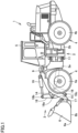
- Fig. 1 is a side view of wheel loader 1 as an exemplary work machine.
- wheel loader 1 includes a vehicular body frame 2, a work implement 3, a travel apparatus 4, and a cab 5.
- a vehicular body of wheel loader 1 is composed of vehicular body frame 2, cab 5, and the like.
- Work implement 3 and travel apparatus 4 are attached to the vehicular body of wheel loader 1.
- a main body of wheel loader 1 includes the vehicular body and travel apparatus 4.
- Travel apparatus 4 serves for travel of the vehicular body of wheel loader 1 and includes running wheels 4a and 4b.
- Wheel loader 1 is a wheeled vehicle provided with running wheels 4a and 4b as rotational bodies for travel, on opposing sides in a lateral direction of the vehicular body. Wheel loader 1 is self-propelled as running wheels 4a and 4b are rotationally driven and can perform desired works with work implement 3.
- Travel apparatus 4 corresponds to an exemplary "travel unit.”
- a direction in which wheel loader 1 travels straight is herein referred to as a fore/aft direction of wheel loader 1.
- a side where work implement 3 is arranged with respect to vehicular body frame 2 is defined as the fore direction and a side opposite to the fore direction is defined as the aft direction.
- the lateral direction of wheel loader 1 refers to a direction orthogonal to the fore/aft direction when wheel loader 1 on a flat ground is viewed in a plan view.
- a right side and a left side in the lateral direction when one faces the fore direction are defined as a right direction and a left direction, respectively.
- An upward/downward direction of wheel loader 1 is a direction orthogonal to the plane defined by the fore/aft direction and the lateral direction.
- a side where the ground is located and a side where the sky is located in the upward/downward direction are defined as a lower side and an upper side, respectively.
- Vehicular body frame 2 includes a front frame 2a and a rear frame 2b. Front frame 2a is arranged in front of rear frame 2b. Front frame 2a and rear frame 2b are attached to each other as being laterally swingable.
- a pair of steering cylinders 11 is attached across front frame 2a and rear frame 2b.
- Steering cylinder 11 is a hydraulic cylinder.
- Vehicular body frame 2 in an articulated structure is composed of front frame 2a and rear frame 2b.
- Wheel loader 1 is an articulated work machine in which front frame 2a and rear frame 2b are coupled to allow a flection operation.
- Work implement 3 and a pair of running wheels (front wheels) 4a are attached to front frame 2a.
- Work implement 3 is attached in front of the main body of wheel loader 1.
- Work implement 3 is supported by the vehicular body of wheel loader 1.
- Work implement 3 includes a boom 14 and a bucket 6.
- Bucket 6 is arranged at a tip end of work implement 3.
- Bucket 6 is a work tool for excavation and loading.
- a cutting edge 6a is a tip end portion of bucket 6.
- a rear surface 6b is a part of an outer surface of bucket 6.
- Rear surface 6b is formed from a plane. Rear surface 6b extends rearward from cutting edge 6a.
- Boom 14 has a base end portion rotatably attached to front frame 2a by a boom pin 9.
- Bucket 6 is rotatably attached to boom 14 by a bucket pin 17 located at a tip end of boom 14.
- Boom pin 9 and bucket pin 17 correspond to "a plurality of articulations" of work implement 3.
- Work implement 3 further includes a bell crank 18 and a link 15.
- Bell crank 18 is rotatably supported on boom 14 by a support pin 18a located substantially in a center of boom 14.
- Link 15 is coupled to a coupling pin 18c provided at a tip end portion of bell crank 18.
- Link 15 couples bell crank 18 and bucket 6 to each other.
- Front frame 2a and boom 14 are coupled to each other by a pair of boom cylinders 16.
- Boom cylinder 16 is a hydraulic cylinder.
- Boom cylinder 16 rotationally drives boom 14 upward and downward around boom pin 9.
- Boom cylinder 16 has a base end attached to front frame 2a.
- Boom cylinder 16 has a tip end attached to boom 14.
- Boom cylinder 16 is a hydraulic actuator that operates boom 14 upward and downward with respect to front frame 2a. With movement upward and downward of boom 14, bucket 6 attached at the tip end of boom 14 also moves upward and downward.
- a bucket cylinder 19 couples bell crank 18 and front frame 2a to each other.
- Bucket cylinder 19 has a base end attached to front frame 2a.
- Bucket cylinder 19 has a tip end attached to a coupling pin 18b provided at a base end portion of bell crank 18.
- Bucket cylinder 19 is a hydraulic actuator to cause bucket 6 to pivot upward and downward with respect to boom 14.
- Bucket cylinder 19 is a work tool cylinder that drives bucket 6.
- Bucket cylinder 19 rotationally drives bucket 6 around bucket pin 17.
- Bucket 6 is constructed as being operable with respect to boom 14.
- Bucket 6 is constructed as being operable with respect to front frame 2a.
- Boom cylinder 16 and bucket cylinder 19 correspond to an exemplary "work implement actuator" that drives work implement 3.
- Cab 5 on which an operator rides and a pair of running wheels (rear wheels) 4b are attached to rear frame 2b.
- Cab 5 in a box shape is arranged in the rear of boom 14.
- Cab 5 is carried on vehicular body frame 2.
- a seat where the operator of wheel loader 1 is seated, an operation apparatus 8 which will be described later, and the like are arranged.
- Fig. 2 is a block diagram showing an overall configuration of a control system that controls wheel loader 1.
- An engine 21 is a drive source that generates drive force to drive work implement 3 and travel apparatus 4, and it is, for example, a diesel engine.
- a motor driven by a power storage, instead of engine 21, may be employed as the drive source, or both of the engine and the motor may be employed.
- Output from engine 21 is controlled by adjustment of an amount of fuel to be injected into a cylinder of engine 21.
- Drive force generated by engine 21 is transmitted to a transmission 23.
- Transmission 23 converts drive force into appropriate torque and a rotation speed.
- An axle 25 is connected to an output shaft of transmission 23.
- Drive force converted by transmission 23 is transmitted to axle 25.
- Drive force is transmitted from axle 25 to running wheels 4a and 4b ( Fig. 1 ).
- Wheel loader 1 thus travels.
- both of running wheel 4a and running wheel 4b implement drive wheels for travel of wheel loader 1 upon receiving drive force.
- Work implement pump 13 is a hydraulic pump driven by engine 21 to activate work implement 3 with hydraulic oil it delivers.
- Work implement 3 is driven by hydraulic oil from work implement pump 13.
- Hydraulic oil delivered by work implement pump 13 is supplied to boom cylinder 16 and bucket cylinder 19 through a main valve 32.
- boom cylinder 16 extends and contracts upon receiving supply of hydraulic oil
- boom 14 moves upward and downward.
- bucket cylinder 19 extends and contracts upon receiving supply of hydraulic oil
- bucket 6 pivots upward and downward.
- Wheel loader 1 includes a vehicular body controller 50.
- Vehicular body controller 50 includes an engine controller 60, a transmission controller 70, and a work implement controller 80.
- Vehicular body controller 50 is generally implemented by reading of various programs by a central processing unit (CPU). Vehicular body controller 50 includes a not-shown memory. The memory functions as a work memory, and various programs for performing functions of wheel loader 1 are stored in the memory.
- CPU central processing unit
- Operation apparatus 8 is provided in cab 5. Operation apparatus 8 is operated by an operator. Operation apparatus 8 includes a plurality of types of operation members operated by the operator to operate wheel loader 1. Operation apparatus 8 includes an accelerator pedal 41 and a work implement control lever 42. Operation apparatus 8 may include a steering wheel, a shift lever, and the like which are not shown.
- Accelerator pedal 41 is operated to set the target number of rotations of engine 21.
- Engine controller 60 controls output from engine 21 based on an amount of operation onto accelerator pedal 41. With increase in amount of operation (amount of pressing) onto accelerator pedal 41, output from engine 21 increases. With decrease in amount of operation onto accelerator pedal 41, output from engine 21 decreases.
- Transmission controller 70 controls transmission 23 based on the amount of operation onto accelerator pedal 41.
- Work implement control lever 42 is operated to operate work implement 3.
- Work implement controller 80 controls electromagnetic proportional control valves 35 and 36 based on the amount of operation onto work implement control lever 42.
- Electromagnetic proportional control valve 35 switches main valve 32 such that bucket cylinder 19 contracts to move bucket 6 in a dump direction (a direction in which the cutting edge of bucket 6 is lowered). Electromagnetic proportional control valve 35 switches main valve 32 such that bucket cylinder 19 extends to move bucket 6 in a tilt direction (a direction in which the cutting edge of bucket 6 is raised). Electromagnetic proportional control valve 36 switches main valve 32 such that boom cylinder 16 contracts to lower boom 14. Electromagnetic proportional control valve 36 switches main valve 32 such that boom cylinder 16 extends to raise boom 14.
- a machine monitor 51 shows various types of information upon receiving input of a command signal from vehicular body controller 50.
- the various types of information shown on machine monitor 51 may be, for example, information on works performed by wheel loader 1, vehicular body information such as an amount of remaining fuel, a temperature of coolant, and a temperature of hydraulic oil, an image of surroundings obtained by image pick-up of the surroundings of wheel loader 1, and the like.
- Machine monitor 51 may be implemented by a touch panel, and in this case, a signal generated by touching by the operator onto a part of machine monitor 51 is outputted from machine monitor 51 to vehicular body controller 50.
- Wheel loader 1 in the present embodiment performs excavation and loading works to scoop an excavation target such as soil and to load the excavation target onto a loading target such as a dump truck.
- Fig. 3 is a plan view of wheel loader 1 that performs excavation and loading works.
- Fig. 3 illustrates wheel loader 1 that performs what is called a V shape work.
- Fig. 3 (A) illustrates wheel loader 1 that performs what is called unloaded forward travel. Wheel loader 1 travels forward along an excavation path R1 toward an excavation target 310 such as soil. Wheel loader 1 plunges bucket 6 into excavation target 310 and stops forward travel. By raising bucket 6 with cutting edge 6a of bucket 6 dug into excavation target 310, the excavation work to scoop excavation target 310 in bucket 6 is performed.
- Fig. 3 (B) illustrates wheel loader 1 that performs what is called loaded rearward travel.
- Excavation target 310 has been loaded in bucket 6.
- Wheel loader 1 travels rearward along excavation path R1 to a position from which it started forward travel in Fig. 3 (A) .
- Fig. 3 (C) illustrates wheel loader 1 that performs what is called loaded forward travel.
- wheel loader 1 travels forward toward a vessel 301 of a dump truck 300.
- Wheel loader 1 travels forward along a loading path R2 from the position where it started forward travel in Fig. 3 (A) toward dump truck 300.
- Vessel 301 corresponds to an exemplary "loading target" into which loads in bucket 6 are to be loaded.
- Fig. 3 (D) illustrates wheel loader 1 that performs what is called unloaded rearward travel. While bucket 6 is empty as a result of full ejection of excavation target 310 in bucket 6 into vessel 301 of dump truck 300, wheel loader 1 travels rearward along loading path R2 to the position where it started forward travel in Fig. 3 (C) .
- Wheel loader 1 can thus repeatedly perform a series of works including excavation, rearward travel, dump approach, soil ejection, and rearward travel.
- FIG. 4 is a block diagram showing a configuration of an automatic control system that controls wheel loader 1.
- An automation controller 100 is configured to transmit and receive a signal to and from vehicular body controller 50 described with reference to Fig. 2 .
- Automation controller 100 is configured to transmit and receive a signal to and from an external information obtaining unit 110.
- External information obtaining unit 110 includes a perception device 111 and a positional information obtaining device 112.
- Perception device 111 and positional information obtaining device 112 are mounted on wheel loader 1.
- Perception device 111 obtains information on surroundings of wheel loader 1.
- Perception device 111 is attached, for example, to an upper front surface of cab 5.
- Perception device 111 corresponds to an exemplary "object sensor" that detects an object around the main body of wheel loader 1.
- Perception device 111 contactlessly detects a direction of an object outside wheel loader 1 and a distance to the object.
- Perception device 111 is implemented, for example, by light detection and ranging (LiDAR) that obtains information on an object by emission of laser beams.
- Perception device 111 may be implemented by a visual sensor including a camera.
- Perception device 111 may be implemented by radio detection and ranging (Radar) that obtains information on an object by emission of radio waves.
- Perception device 111 may be implemented by an infrared sensor.
- Positional information obtaining device 112 obtains information on a current position of wheel loader 1. Positional information obtaining device 112 obtains, for example, positional information of wheel loader 1 in a global coordinate system with the Earth being defined as a reference, with the use of a satellite positioning system. Positional information obtaining device 112 uses, for example, global navigation satellite systems (GNSS) and includes a GNSS receiver. The satellite positioning system calculates a position of wheel loader 1 by computing a position of an antenna of the GNSS receiver based on a positioning signal received from a satellite by the GNSS receiver.
- GNSS global navigation satellite systems
- Vehicular body controller 50 is configured to transmit and receive a signal to and from a vehicle information obtaining unit 120, and receives input of information on wheel loader 1 obtained by vehicle information obtaining unit 120.
- Vehicle information obtaining unit 120 is composed of various sensors mounted on wheel loader 1.
- Vehicle information obtaining unit 120 includes an articulation angle sensor 121, a vehicle speed sensor 122, a boom angle sensor 123, a bucket angle sensor 124, and a boom cylinder pressure sensor 125.
- Articulation angle sensor 121 detects an articulation angle which is an angle formed between front frame 2a and rear frame 2b, and generates a signal indicating the detected articulation angle. Articulation angle sensor 121 outputs a signal indicating the articulation angle to vehicular body controller 50.
- Vehicle speed sensor 122 detects a speed of movement of wheel loader 1 by travel apparatus 4, for example, by detection of a rotation speed of an output shaft of transmission 23 and generates a signal indicating the detected vehicle speed. Vehicle speed sensor 122 outputs the signal indicating the vehicle speed to vehicular body controller 50. Vehicle speed sensor 122 corresponds to an exemplary "travel sensor" that detects a status of travel of travel apparatus 4 (travel unit).
- Boom angle sensor 123 is implemented, for example, by a rotary encoder provided in boom pin 9 which is a portion of attachment of boom 14 to vehicular body frame 2. Boom angle sensor 123 detects an angle of boom 14 with respect to a horizontal direction and generates a signal indicating the detected angle of boom 14. Boom angle sensor 123 outputs the signal indicating the angle of boom 14 to vehicular body controller 50.
- Bucket angle sensor 124 is implemented, for example, by a rotary encoder provided in support pin 18a which is a rotation shaft of bell crank 18. Bucket angle sensor 124 detects an angle of bucket 6 with respect to boom 14 and generates a signal indicating the detected angle of bucket 6. Bucket angle sensor 124 outputs the signal indicating the angle of bucket 6 to vehicular body controller 50.
- Boom angle sensor 123 and bucket angle sensor 124 correspond to an exemplary "work implement posture sensor” that detects a posture of work implement 3.
- Boom cylinder pressure sensor 125 detects a pressure on a bottom side (boom bottom pressure) of boom cylinder 16 and generates a signal indicating the detected boom bottom pressure. The boom bottom pressure becomes higher while bucket 6 is loaded and becomes lower while the bucket is unloaded. Boom cylinder pressure sensor 125 outputs a signal indicating the boom bottom pressure to vehicular body controller 50.
- Vehicular body controller 50 outputs information inputted from vehicle information obtaining unit 120 to automation controller 100.
- Automation controller 100 receives detection values from vehicle speed sensor 122, boom angle sensor 123, and bucket angle sensor 124 through vehicular body controller 50.
- An actuator 140 is configured to transmit and receive a signal to and from vehicular body controller 50. Upon receiving a command signal from vehicular body controller 50, actuator 140 is driven.
- Actuator 140 includes a brake EPC (electromagnetic proportional control valve) 141 for activation of a brake of travel apparatus 4, a steering EPC 142 for adjustment of a travel direction of wheel loader 1, a work implement EPC 143 for operations of work implement 3, and a hydraulic mechanical transmission (HMT) 144.
- brake EPC electromechanical proportional control valve
- Electromagnetic proportional control valves 35 and 36 shown in Fig. 2 implement work implement EPC 143.
- Transmission 23 shown in Fig. 2 is implemented as HMT 144 that utilizes electronic control.
- Transmission 23 may be a hydro-static transmission (HST).
- a power transmission apparatus that transmits motive power from engine 21 to running wheels 4a and 4b may include an electric drive apparatus such as a diesel electric drive apparatus, and may include any combination of the HMT, the HST, and the electric drive apparatus.
- Transmission controller 70 includes a brake control unit 71 and an accelerator control unit 72.
- Brake control unit 71 outputs a command signal for control of activation of the brake to brake EPC 141.
- Accelerator control unit 72 outputs a command signal for control of the vehicle speed to HMT 144.
- Work implement controller 80 includes a steering control unit 81 and a work implement control unit 82.
- Steering control unit 81 outputs a command signal for control of the travel direction of wheel loader 1 to steering EPC 142.
- Work implement control unit 82 outputs a command signal for control of operations of work implement 3 to work implement EPC 143.
- Automation controller 100 includes a position estimator 101, a path planning unit 102, and a path tracking control unit 103.
- Position estimator 101 estimates an own position of wheel loader 1 based on the positional information obtained by positional information obtaining device 112. Position estimator 101 recognizes a target position based on the external information obtained by perception device 111.
- the target position is, for example, a position of excavation target 310 or dump truck 300 shown in Fig. 3 .
- Perception device 111 may recognize the target position and input the target position to automation controller 100, or position estimator 101 may recognize the target position based on a result of detection by perception device 111.
- Path planning unit 102 generates an optimal path that connects the own position of wheel loader 1 and the target position to each other.
- the optimal path includes a path for travel by travel apparatus 4 and a path for operations of work implement 3.
- Path tracking control unit 103 controls the accelerator, the brake, and steering such that wheel loader 1 travels as following the optimal path generated by path planning unit 102.
- Path tracking control unit 103 outputs a command signal for travel of wheel loader 1 along the optimal path to brake control unit 71, accelerator control unit 72, and steering control unit 81.
- Path tracking control unit 103 controls boom cylinder 16 and bucket cylinder 19 such that work implement 3 operates along the optimal path generated by path planning unit 102.
- Path tracking control unit 103 outputs a command signal for movement of work implement 3 along the optimal path to work implement control unit 82.
- An interface 130 is configured to transmit and receive a signal to and from vehicular body controller 50.
- Interface 130 includes an automation switch 131, an engine emergency stop switch 132, and a mode indicator 133.
- Automation switch 131 is operated by the operator.
- the operator operates automation switch 131 to switch between a manual operation of wheel loader 1 and automatic control of wheel loader 1.
- Engine emergency stop switch 132 is operated by the operator. When an event that requires emergency stop of engine 21 occurs, the operator operates engine emergency stop switch 132. A signal resulting from an operation onto automation switch 131 and engine emergency stop switch 132 is inputted to vehicular body controller 50.
- Mode indicator 133 indicates whether wheel loader 1 is currently in a mode of the manual operation by the operator or an automatic control mode.
- Vehicular body controller 50 outputs a command signal for control of turn-on of the indicator to mode indicator 133.
- Fig. 5 is a flowchart showing a flow of operations to load loads carried in bucket 6 into the loading target under automatic control of wheel loader 1.
- a shape of vessel 301 of dump truck 300 which is the loading target is recognized.
- the shape of dump truck 300 is obtained by LiDAR which is perception device 111.
- Point group data indicating three-dimensional coordinate values of measurement points on dump truck 300 is obtained by irradiating dump truck 300 with laser beams from LiDAR.
- Dump truck 300 is sensed from four directions of the fore direction, the aft direction, the right direction, and the left direction, and the shape of vessel 301 can be recognized based on information on a point group.
- the recognized shape of vessel 301 is inputted to automation controller 100.
- perception device 111 recognizes a reference point P of dump truck 300.
- Dump truck 300 is sensed by LiDAR which is perception device 111.
- Automation controller 100 recognizes the position of vessel 301 based on comparison between the point group sensed by perception device 111 and a master point group representing the shape of vessel 301.
- Automation controller 100 sets as reference point P, an upper end of a side surface of vessel 301 of dump truck 300 recognized by LiDAR which is perception device 111.
- step S102 automation controller 100 sets coordinates with respect to reference point P, of target positions a to d of cutting edge 6a of bucket 6 moved under automatic control.
- Cutting edge 6a of bucket 6 corresponds to an exemplary "feature point" set in work implement 3.
- the feature point is not limited to cutting edge 6a of bucket 6, and another point of work implement 3 may be set as the feature point.
- FIG. 6 is a diagram schematically showing arrangement of vessel 301 and wheel loader 1 at the time of start of dump approach.
- Fig. 6 and subsequent Figs. 7 to 10 schematically show vessel 301 viewed from the fore/aft direction of dump truck 300, and schematically show a part on a front side of wheel loader 1 that approaches vessel 301 from the left side or the right side of dump truck 300.
- Target position a is set as a position through which cutting edge 6a of bucket 6 passes during forward travel of wheel loader 1 toward dump truck 300.
- Target position a is a position where the operation of bucket 6 in the dump direction is started for loading loads in bucket 6 into vessel 301.
- Target position a is set as a point more distant from vessel 301 than reference point P.
- Target position a is set as a point in front of reference point P of vessel 301.
- Target position a is set as a point higher than reference point P of vessel 301.
- Target position a corresponds to an exemplary "first target position.”
- Target position b is set as a position where cutting edge 6a of bucket 6 passes after it passes through target position a and moves beyond reference point P.
- Target position b is set as a point where cutting edge 6a of bucket 6 moves toward a farthest side (the left side in Figs. 6 to 10 ) while wheel loader 1 travels forward to approach vessel 301.
- Target position b is located above vessel 301.
- Target position b corresponds to an exemplary "second target position.”
- Target position c is set as a position where cutting edge 6a of bucket 6 passes after it passes through target position b.
- Target position c is a position where the operation of bucket 6 in the dump direction is stopped. The operation of bucket 6 in the dump direction is continued during a period from passage of cutting edge 6a of bucket 6 through target position a until cutting edge 6a of bucket 6 reaches target position c.
- Target position c is located above vessel 301.
- Target position c is set to be closer to reference point P than target position b.
- Target position d is set as a position where cutting edge 6a of bucket 6 passes after it passes through target position c.
- Target position d is a position where the operation to raise boom 14 is stopped.
- wheel loader 1 during forward travel toward dump truck 300 is performing the operation to raise boom 14.
- the operation to raise boom 14 is continued during a period from start of dump approach by wheel loader 1 until cutting edge 6a of bucket 6 reaches target position d.
- Target position d is located above vessel 301.
- Target position d is set to be closer to reference point P than target position c.
- an xy coordinate system with reference point P being defined as an origin is set.
- An x axis represents the lateral direction of dump truck 300 that passes through reference point P.
- a direction away from vessel 301 with reference point P being defined as the reference is defined as a +x direction.
- a y axis represents the upward/downward direction that passes through reference point P.
- An upward direction from reference point P is defined as a +y direction.
- a bucket angle ⁇ shown in Fig. 6 represents an angle formed between the ground and rear surface 6b of bucket 6.
- Bucket angle ⁇ may be an angle formed between rear surface 6b of bucket 6 and a horizontal plane with the vehicular body being defined as the reference.
- Target positions a to d are determined by giving horizontal and vertical positions, that is, an x coordinate and a y coordinate, of cutting edge 6a of bucket 6 with reference point P being defined as the reference.
- Target position a is set as a position where a height position of cutting edge 6a is highest (the y coordinate having a maximum value) during the loading work.
- Target position c is set as a position where the height position of cutting edge 6a is lowest (the y coordinate having a minimum value) during soil ejection from bucket 6.
- Target position a is set at a position where the y coordinate is on a positive side.
- Target position c is set at a position where the y coordinate is on a negative side.
- Target position a is set at a position where the x coordinate is on the positive side.
- Target positions b, c, and d are set at positions where the x coordinates are on the negative side.
- Target position b is set as a position where the x coordinate has a minimum value during soil ejection from bucket 6.
- Bucket angle ⁇ at the time when cutting edge 6a of bucket 6 is located at each target position is also set.
- the posture of work implement 3 at the time when cutting edge 6a of bucket 6 is located at each target position is determined by the x coordinate and the y coordinate of each target position and bucket angle ⁇ at each target position.
- the posture (a target posture) of work implement 3 at the time when cutting edge 6a of bucket 6 is located at each target position is stored in automation controller 100.
- a length of boom cylinder 16 and a length of bucket cylinder 19 at the time when cutting edge 6a of bucket 6 is located at each target position are determined based on the target posture at the time when cutting edge 6a of bucket 6 is located at each target position.
- the x coordinate and the y coordinate of each target position and bucket angle ⁇ at each target position can be determined by analyzing a trace of cutting edge 6a when the skilled operator performs the loading work to extract a characterizing position and extracting the posture of work implement 3 at that characteristic position.
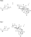
- Fig. 7 is a diagram schematically showing the posture of wheel loader 1 when a dump operation of bucket 6 is started.
- Fig. 8 is a diagram schematically showing the posture of wheel loader 1 when cutting edge 6a reaches the farthest position.
- Fig. 9 is a diagram schematically showing the posture of wheel loader 1 when the dump operation of bucket 6 is stopped.
- Fig. 10 is a diagram schematically showing the posture of wheel loader 1 when the operation to raise boom 14 is stopped.
- cutting edge 6a of bucket 6 is located at target position a.
- cutting edge 6a is located at target position b.
- cutting edge 6a is located at target position c.
- Fig. 10 cutting edge 6a is located at target position d.
- Fig. 11 shows a graph of change in cylinder length during the loading work.
- the abscissa in Fig. 11 represents lapse of time and extension lines are drawn at times when cutting edge 6a passes through target positions a, b, c, and d.
- the ordinate in Fig. 11 represents the lengths of boom cylinder 16 and bucket cylinder 19.
- wheel loader 1 continues forward travel until cutting edge 6a reaches target position b after it passes through target position a.
- the length of boom cylinder 16 keeps increasing, and hence boom 14 keeps rising.
- the operation of bucket 6 in the dump direction is started, and bucket 6 continues operating in the dump direction until the cutting edge reaches target position b.
- the length of bucket cylinder 19 keeps decreasing.
- target position b is lower in height position than target position a.
- the value of the y coordinate of target position b is smaller than the value of the y coordinate of target position a.
- wheel loader 1 continues forward travel until cutting edge 6a reaches target position c after it passes through target position b.
- the length of boom cylinder 16 keeps increasing, and hence boom 14 keeps rising.
- the length of bucket cylinder 19 keeps decreasing, and hence bucket 6 continues operating in the dump direction.
- target position c is lower in height position than target position b.
- the value of the y coordinate of target position c is smaller than the value of the y coordinate of target position b.
- boom 14 keeps rising. During soil ejection from bucket 6, boom 14 keeps rising. During loading of loads into dump truck 300, boom 14 keeps rising. During the dump operation of bucket 6, wheel loader 1 moves toward vessel 301 of dump truck 300, and hence it also continues forward travel.
- the length of boom cylinder 16 is set to be constant. At this time, the height position of boom 14 is highest. At the time when boom 14 stops rising, loads in bucket 6 have already been loaded in vessel 301 and bucket 6 is in an unloaded state. Since a weight of loads in bucket 6 has become smaller, influence by inertia at the time when boom 14 is stopped is less. Therefore, vibration of the vehicular body is less likely.
- Loads in bucket 6 can be loaded into vessel 301 without contact of bucket 6 with vessel 301, by moving cutting edge 6a of bucket 6 to sequentially pass through target position a, target position b, target position c, and target position d.
- automatic control to thus move bucket 6 to wheel loader 1, operations of work implement 3 equivalent to operations performed by the skilled operator can be realized.
- step S103 automation controller 100 recognizes the current positions of wheel loader 1 and work implement 3.
- Positional information obtaining device 112 obtains the current position of the vehicular body of wheel loader 1 and obtains the posture of the work implement with respect to the vehicular body with boom angle sensor 123 and bucket angle sensor 124, to thereby recognize the current positions of wheel loader 1 and work implement 3 in the global coordinate system.
- the position of cutting edge 6a of bucket 6 relative to vessel 301 of dump truck 300 can be calculated based on the current positions of wheel loader 1 and work implement 3 and the current position of dump truck 300 in the global coordinate system.
- perception device 111 may be used to obtain the direction and the distance of reference point P of vessel 301 of dump truck 300 from a position of arrangement of perception device 111, to thereby calculate the current position of cutting edge 6a of bucket 6 relative to reference point P.
- cutting edge 6a is recognized as not having reached target position a yet, cutting edge 6a is recognized as having passed through target position a and being located between target position a and target position b, cutting edge 6a is recognized as having passed through target position b and being located between target position b and target position c, etc. Furthermore, a target position to which cutting edge 6a is headed next is recognized.
- target position a is recognized as a position to which the cutting edge is headed next
- target position b is recognized as a position to which the cutting edge is headed next
- step S104 automation controller 100 recognizes the length of boom cylinder 16 and the length of bucket cylinder 19 at the current position.
- Boom angle sensor 123 detects the angle of boom 14.
- Bucket angle sensor 124 detects the angle of bucket 6.
- the posture of work implement 3 is determined by the angle of boom 14 and the angle of bucket 6.
- the length of boom cylinder 16 and the length of bucket cylinder 19 at the current position are recognized based on the posture of the work implement.
- an angle sensor that detects an angle of bell crank 18 and an angle sensor that detects an angle of link 15 may be provided.
- a stroke sensor that detects a length of a cylinder stroke may be provided in boom cylinder 16 and bucket cylinder 19.
- step S105 automation controller 100 calculates a difference between the length of boom cylinder 16 and the length of bucket cylinder 19 at the current position recognized in step S104 and the length of boom cylinder 16 and the length of bucket cylinder 19 (which will be referred to as a target cylinder length below) at the target position to which cutting edge 6a is headed next. Automation controller 100 calculates how much the cylinder is to be moved until cutting edge 6a reaches the next target position.
- automation controller 100 refers to a current vehicle speed and determines a target cylinder stroke speed that achieves the target cylinder length at the time when cutting edge 6a reaches the target position to which the cutting edge is headed next.
- Automation controller 100 controls boom cylinder 16 and bucket cylinder 19 such that work implement 3 takes, when cutting edge 6a reaches the target position to which it is headed next, a target posture corresponding to that target position.
- the current vehicle speed is obtained by vehicle speed sensor 122. Time until the cutting edge reaches the next target position can be calculated based on the current position of cutting edge 6a and the current vehicle speed.
- the target cylinder stroke speed can be determined by dividing the difference in cylinder length calculated in step S105 by time until the cutting edge reaches the next target position.
- An amount of cylinder stroke while wheel loader 1 travels a unit distance may be determined. Travel of the unit distance by wheel loader 1 may be determined based on the vehicle speed or may be sensed by perception device 111.
- automation controller 100 outputs a command current corresponding to the target cylinder stroke speed to vehicular body controller 50.
- Automation controller 100 outputs a command to extend and contract boom cylinder 16 and bucket cylinder 19 at the target cylinder stroke speed to work implement control unit 82 of work implement controller 80.
- the command to extend and contract boom cylinder 16 and bucket cylinder 19 at the target cylinder stroke speed is outputted from work implement control unit 82 to work implement EPC 143.
- step S108 as work implement EPC 143 that has received the command signal adjusts an opening, appropriate hydraulic oil is supplied to boom cylinder 16 and bucket cylinder 19. Boom cylinder 16 and bucket cylinder 19 thus operate.
- step S109 automation controller 100 recognizes the current lengths of boom cylinder 16 and bucket cylinder 19 as in step S104. Automation controller 100 determines whether or not the current lengths of boom cylinder 16 and bucket cylinder 19 have reached the target cylinder lengths.
- step S109 When determination as having reached the target cylinder lengths is made in determination in step S109 (YES in step S109), the process proceeds to step S110 and automation controller 100 determines whether or not there is a next target position.
- step S109 When determination as not having reached the target cylinder length is made in determination in step S109 (NO in step S109) and when it is determined in step S 110 that there is a next target position (YES in step S110), the process returns to step S103 and processing for extending and contracting boom cylinder 16 and bucket cylinder 19 based on the current position of work implement 3 is repeated.
- the cylinder speed is successively changed in accordance with the current position of cutting edge 6a of bucket 6.
- the current position of cutting edge 6a is displaced from a position based on the cylinder speed set in previous processing, the cylinder speed is adjusted.
- step S 110 When it is determined in step S 110 that there is no next target position (NO in step S110), the loading work ends, which corresponds to a case where the next target position is not set after the end of target position d in the present embodiment.
- automation controller 100 starts drive of bucket cylinder 19 to operate bucket 6 in the dump direction.
- automation controller 100 continues drive of bucket cylinder 19 to operate bucket 6 in the dump direction until cutting edge 6a of bucket 6 moves beyond reference point P and reaches target position b above vessel 301. With such an operation, loads in bucket 6 can reliably be loaded in vessel 301.
- automation controller 100 continues drive of bucket cylinder 19 to operate bucket 6 in the dump direction also after cutting edge 6a of bucket 6 passes through target position b. With such an operation, loads can more reliably be ejected from bucket 6.
- automation controller 100 starts drive of boom cylinder 16 to raise boom 14 before cutting edge 6a of bucket 6 reaches target position a and continues drive of boom cylinder 16 to raise boom 14 also after cutting edge 6a passes through target position a.
- the operation to start dump of bucket 6 while boom 14 is being raised can thus reliably be realized.
- Contact between the upper end of the side surface of vessel 301 set as reference point P and work implement 3 can be avoided.
- automation controller 100 continues drive of boom cylinder 16 to raise boom 14 until cutting edge 6a of bucket 6 reaches target position b. With such an operation, the loading work can reliably be performed without the operation of work implement 3 being stopped.
- automation controller 100 continues drive of boom cylinder 16 to raise boom 14 also after cutting edge 6a of bucket 6 passes through target position b. With such an operation, the loading work can reliably be performed without the operation of work implement 3 being stopped.
- automation controller 100 continues drive of boom cylinder 16 to raise boom 14 until it stops drive of bucket cylinder 19 to operate bucket 6 in the dump direction. With such an operation, the loading work can reliably be performed without the operation of work implement 3 being stopped.
- automation controller 100 continues drive of boom cylinder 16 to raise boom 14 until forward travel of travel apparatus 4 is stopped. With such an operation, the loading work can reliably be performed without the operation of work implement 3 being stopped.
- the target posture of work implement 3 when cutting edge 6a of bucket 6 is located at target position a is stored in automation controller 100.
- Automation controller 100 controls boom cylinder 16 and bucket cylinder 19 to set work implement 3 into the target posture when cutting edge 6a reaches target position a. With such an operation, contact between work implement 3 and vessel 301 can reliably be avoided.
- Automation controller 100 included in the automatic control system for wheel loader 1 described in the embodiment above does not necessarily have to be mounted on wheel loader 1.
- Such a system that a controller mounted on wheel loader 1 performs processing for transmitting information obtained by external information obtaining unit 110, vehicle information obtaining unit 120, and the like to an external controller and the external controller that receives a signal automatically controls wheel loader 1 may be configured.
- the external controller may be arranged at a worksite of wheel loader 1 or at a remote location distant from the worksite of wheel loader 1.
- wheel loader 1 is a manned vehicle including cab 5 on which the operator rides.
- Wheel loader 1 may be an unmanned vehicle. Wheel loader 1 does not have to include cab 5 on which the operator rides for performing operations. Wheel loader 1 does not have to be equipped with a function for manipulating by the operator who rides on the cab.
- Wheel loader 1 may be a work machine dedicated for remote control. Wheel loader 1 may be manipulated through a wireless signal from a remote control device.
- a work machine includes
- the controller continues drive of the work implement actuator to operate the bucket in the dump direction until the feature point reaches a second target position above the loading target.
- the controller continues drive of the work implement actuator to operate the bucket in the dump direction also after the feature point passes through the second target position.
- the controller continues drive of the work implement actuator to raise the boom until the feature point reaches the second target position.
- the controller continues drive of the work implement actuator to raise the boom also after the feature point passes through the second target position.
- the controller continues drive of the work implement actuator to raise the boom until drive of the work implement actuator to operate the bucket in the dump direction is stopped.
- the controller continues drive of the work implement actuator to raise the boom until forward travel of the travel unit is stopped.
- the controller sets an upper end of a side surface of the loading target recognized by the object sensor as a reference point, and calculates a current position of the feature point relative to the reference point.
- a target posture of the work implement at the time when the feature point is located at the first target position is stored in the controller, and the controller controls the work implement actuator to set the work implement into the target posture when the feature point reaches the first target position.
Landscapes
- Engineering & Computer Science (AREA)
- Mining & Mineral Resources (AREA)
- Civil Engineering (AREA)
- General Engineering & Computer Science (AREA)
- Structural Engineering (AREA)
- Mechanical Engineering (AREA)
- Operation Control Of Excavators (AREA)
Abstract
Description
- The present disclosure relates to a work machine, a system including a work machine, and a method of controlling a work machine.
-
WO2016/152994 (PTL 1) discloses control to move a boom and a bucket to target positions obtained in accordance with a moving distance of a wheel loader when the wheel loader is in a state of loaded forward travel in which the wheel loader travels forward with the bucket being loaded. - PTL 1:
WO2016/152994 - A wheel loader that repeatedly performs an excavation work and a loading work has been demanded to achieve reduction in cycle time of works to improve workability.
- The present disclosure proposes a work machine, a system including a work machine, and a method of controlling a work machine that achieve reduction in cycle time of works.
- Each of a work machine and a system including the work machine according to one aspect of the present disclosure includes a main body of the work machine including a travel unit, a work implement attached in front of the main body of the work machine, the work implement including a bucket at a tip end, a work implement actuator that drives the work implement with respect to the main body of the work machine, a travel sensor that detects a state of travel of the travel unit, a work implement posture sensor that detects a posture of the work implement, an object sensor that detects an object around the main body of the work machine, and a controller that provides a command to drive the work implement actuator based on detection values from the travel sensor, the work implement posture sensor, and the object sensor. The controller recognizes a loading target into which loads in the bucket are to be loaded, based on detection of the object. The controller starts drive of the work implement actuator to operate the bucket in a dump direction while forward travel of the travel unit continues, at a time point when a feature point of the bucket reaches a first target position in front of the loading target and higher than the loading target while the work implement approaches the loading target by forward travel of the travel unit.
- A method of controlling a work machine according to one aspect of the present disclosure includes recognizing a loading target into which loads in a bucket are to be loaded, based on an object detection signal, causing a travel unit to travel forward to bring a work implement closer to the loading target, and starting drive of a work implement actuator to operate the bucket in a dump direction while forward travel of the travel unit continues, at a time point when a feature point of the bucket reaches a first target position in front of the loading target and higher than the loading target.
- According to the work machine, the system including the work machine, and the method of controlling the work machine in the present disclosure, the cycle time of works can be reduced.
-
-
Fig. 1 is a side view of a wheel loader as an exemplary work machine. -
Fig. 2 is a block diagram showing an overall configuration of a control system that controls the wheel loader. -
Fig. 3 is a plan view of the wheel loader that performs excavation and loading works. -
Fig. 4 is a block diagram showing a configuration of an automatic control system that controls the wheel loader. -
Fig. 5 is a flowchart showing a flow of operations to load loads carried in a bucket into a loading target under automatic control. -
Fig. 6 is a diagram schematically showing arrangement of a vessel and the wheel loader at the time of start of dump approach. -
Fig. 7 is a diagram schematically showing a posture of the wheel loader when a bucket dump operation is started. -
Fig. 8 is a diagram schematically showing a posture of the wheel loader when a cutting edge reaches a farthest position. -
Fig. 9 is a diagram schematically showing a posture of the wheel loader when the bucket dump operation is stopped. -
Fig. 10 is a diagram schematically showing a posture of the wheel loader when a boom raising operation is stopped. -
Fig. 11 shows a graph of change in cylinder length during a loading work. - An embodiment will be described below with reference to the drawings. The same components and constituent elements in the description below have the same reference characters allotted and their labels and functions are also the same. Therefore, detailed description thereof will not be repeated. Extraction of any features from the embodiment and any combination thereof are also originally intended.
- In an embodiment, a
wheel loader 1 as an exemplary work machine will be described.Fig. 1 is a side view ofwheel loader 1 as an exemplary work machine. - As shown in
Fig. 1 ,wheel loader 1 includes avehicular body frame 2, a work implement 3, a travel apparatus 4, and acab 5. A vehicular body ofwheel loader 1 is composed ofvehicular body frame 2,cab 5, and the like. Work implement 3 and travel apparatus 4 are attached to the vehicular body ofwheel loader 1. A main body ofwheel loader 1 includes the vehicular body and travel apparatus 4. - Travel apparatus 4 serves for travel of the vehicular body of
wheel loader 1 and includes runningwheels Wheel loader 1 is a wheeled vehicle provided with runningwheels Wheel loader 1 is self-propelled as runningwheels - A direction in which
wheel loader 1 travels straight is herein referred to as a fore/aft direction ofwheel loader 1. In the fore/aft direction ofwheel loader 1, a side wherework implement 3 is arranged with respect tovehicular body frame 2 is defined as the fore direction and a side opposite to the fore direction is defined as the aft direction. The lateral direction ofwheel loader 1 refers to a direction orthogonal to the fore/aft direction whenwheel loader 1 on a flat ground is viewed in a plan view. A right side and a left side in the lateral direction when one faces the fore direction are defined as a right direction and a left direction, respectively. An upward/downward direction ofwheel loader 1 is a direction orthogonal to the plane defined by the fore/aft direction and the lateral direction. A side where the ground is located and a side where the sky is located in the upward/downward direction are defined as a lower side and an upper side, respectively. -
Vehicular body frame 2 includes afront frame 2a and arear frame 2b.Front frame 2a is arranged in front ofrear frame 2b.Front frame 2a andrear frame 2b are attached to each other as being laterally swingable. - A pair of
steering cylinders 11 is attached acrossfront frame 2a andrear frame 2b.Steering cylinder 11 is a hydraulic cylinder. Assteering cylinder 11 extends and contracts with hydraulic oil from a steering pump, a direction of travel ofwheel loader 1 laterally changes.Vehicular body frame 2 in an articulated structure is composed offront frame 2a andrear frame 2b.Wheel loader 1 is an articulated work machine in whichfront frame 2a andrear frame 2b are coupled to allow a flection operation. - Work implement 3 and a pair of running wheels (front wheels) 4a are attached to
front frame 2a.Work implement 3 is attached in front of the main body ofwheel loader 1.Work implement 3 is supported by the vehicular body ofwheel loader 1.Work implement 3 includes aboom 14 and abucket 6.Bucket 6 is arranged at a tip end of work implement 3.Bucket 6 is a work tool for excavation and loading. Acutting edge 6a is a tip end portion ofbucket 6. Arear surface 6b is a part of an outer surface ofbucket 6.Rear surface 6b is formed from a plane.Rear surface 6b extends rearward from cuttingedge 6a. -
Boom 14 has a base end portion rotatably attached tofront frame 2a by aboom pin 9.Bucket 6 is rotatably attached to boom 14 by abucket pin 17 located at a tip end ofboom 14.Boom pin 9 andbucket pin 17 correspond to "a plurality of articulations" of work implement 3. - Work implement 3 further includes a bell crank 18 and a
link 15. Bell crank 18 is rotatably supported onboom 14 by asupport pin 18a located substantially in a center ofboom 14.Link 15 is coupled to acoupling pin 18c provided at a tip end portion ofbell crank 18.Link 15 couples bell crank 18 andbucket 6 to each other. -
Front frame 2a andboom 14 are coupled to each other by a pair ofboom cylinders 16.Boom cylinder 16 is a hydraulic cylinder.Boom cylinder 16 rotationally drives boom 14 upward and downward aroundboom pin 9.Boom cylinder 16 has a base end attached tofront frame 2a.Boom cylinder 16 has a tip end attached toboom 14.Boom cylinder 16 is a hydraulic actuator that operatesboom 14 upward and downward with respect tofront frame 2a. With movement upward and downward ofboom 14,bucket 6 attached at the tip end ofboom 14 also moves upward and downward. - A
bucket cylinder 19 couples bell crank 18 andfront frame 2a to each other.Bucket cylinder 19 has a base end attached tofront frame 2a.Bucket cylinder 19 has a tip end attached to acoupling pin 18b provided at a base end portion ofbell crank 18.Bucket cylinder 19 is a hydraulic actuator to causebucket 6 to pivot upward and downward with respect toboom 14.Bucket cylinder 19 is a work tool cylinder that drivesbucket 6.Bucket cylinder 19rotationally drives bucket 6 aroundbucket pin 17.Bucket 6 is constructed as being operable with respect toboom 14.Bucket 6 is constructed as being operable with respect tofront frame 2a. -
Boom cylinder 16 andbucket cylinder 19 correspond to an exemplary "work implement actuator" that drives work implement 3. -
Cab 5 on which an operator rides and a pair of running wheels (rear wheels) 4b are attached torear frame 2b.Cab 5 in a box shape is arranged in the rear ofboom 14.Cab 5 is carried onvehicular body frame 2. Incab 5, a seat where the operator ofwheel loader 1 is seated, anoperation apparatus 8 which will be described later, and the like are arranged. -
Fig. 2 is a block diagram showing an overall configuration of a control system that controlswheel loader 1. - An
engine 21 is a drive source that generates drive force to drive work implement 3 and travel apparatus 4, and it is, for example, a diesel engine. A motor driven by a power storage, instead ofengine 21, may be employed as the drive source, or both of the engine and the motor may be employed. Output fromengine 21 is controlled by adjustment of an amount of fuel to be injected into a cylinder ofengine 21. - Drive force generated by
engine 21 is transmitted to atransmission 23.Transmission 23 converts drive force into appropriate torque and a rotation speed. Anaxle 25 is connected to an output shaft oftransmission 23. Drive force converted bytransmission 23 is transmitted toaxle 25. Drive force is transmitted fromaxle 25 to runningwheels Fig. 1 ).Wheel loader 1 thus travels. Inwheel loader 1 in the embodiment, both of runningwheel 4a and runningwheel 4b implement drive wheels for travel ofwheel loader 1 upon receiving drive force. - Some of drive force from
engine 21 is transmitted to a work implementpump 13. Work implementpump 13 is a hydraulic pump driven byengine 21 to activate work implement 3 with hydraulic oil it delivers. Work implement 3 is driven by hydraulic oil from work implementpump 13. Hydraulic oil delivered by work implementpump 13 is supplied toboom cylinder 16 andbucket cylinder 19 through amain valve 32. Asboom cylinder 16 extends and contracts upon receiving supply of hydraulic oil,boom 14 moves upward and downward. Asbucket cylinder 19 extends and contracts upon receiving supply of hydraulic oil,bucket 6 pivots upward and downward. -
Wheel loader 1 includes avehicular body controller 50.Vehicular body controller 50 includes anengine controller 60, atransmission controller 70, and a work implementcontroller 80. -
Vehicular body controller 50 is generally implemented by reading of various programs by a central processing unit (CPU).Vehicular body controller 50 includes a not-shown memory. The memory functions as a work memory, and various programs for performing functions ofwheel loader 1 are stored in the memory. -
Operation apparatus 8 is provided incab 5.Operation apparatus 8 is operated by an operator.Operation apparatus 8 includes a plurality of types of operation members operated by the operator to operatewheel loader 1.Operation apparatus 8 includes anaccelerator pedal 41 and a work implementcontrol lever 42.Operation apparatus 8 may include a steering wheel, a shift lever, and the like which are not shown. -
Accelerator pedal 41 is operated to set the target number of rotations ofengine 21.Engine controller 60 controls output fromengine 21 based on an amount of operation ontoaccelerator pedal 41. With increase in amount of operation (amount of pressing) ontoaccelerator pedal 41, output fromengine 21 increases. With decrease in amount of operation ontoaccelerator pedal 41, output fromengine 21 decreases.Transmission controller 70controls transmission 23 based on the amount of operation ontoaccelerator pedal 41. - Work implement
control lever 42 is operated to operate work implement 3. Work implementcontroller 80 controls electromagneticproportional control valves control lever 42. - Electromagnetic
proportional control valve 35 switchesmain valve 32 such thatbucket cylinder 19 contracts to movebucket 6 in a dump direction (a direction in which the cutting edge ofbucket 6 is lowered). Electromagneticproportional control valve 35 switchesmain valve 32 such thatbucket cylinder 19 extends to movebucket 6 in a tilt direction (a direction in which the cutting edge ofbucket 6 is raised). Electromagneticproportional control valve 36 switchesmain valve 32 such thatboom cylinder 16 contracts tolower boom 14. Electromagneticproportional control valve 36 switchesmain valve 32 such thatboom cylinder 16 extends to raiseboom 14. - A machine monitor 51 shows various types of information upon receiving input of a command signal from
vehicular body controller 50. The various types of information shown onmachine monitor 51 may be, for example, information on works performed bywheel loader 1, vehicular body information such as an amount of remaining fuel, a temperature of coolant, and a temperature of hydraulic oil, an image of surroundings obtained by image pick-up of the surroundings ofwheel loader 1, and the like. Machine monitor 51 may be implemented by a touch panel, and in this case, a signal generated by touching by the operator onto a part of machine monitor 51 is outputted from machine monitor 51 tovehicular body controller 50. -
Wheel loader 1 in the present embodiment performs excavation and loading works to scoop an excavation target such as soil and to load the excavation target onto a loading target such as a dump truck.Fig. 3 is a plan view ofwheel loader 1 that performs excavation and loading works.Fig. 3 illustrateswheel loader 1 that performs what is called a V shape work. -
Fig. 3 (A) illustrateswheel loader 1 that performs what is called unloaded forward travel.Wheel loader 1 travels forward along an excavation path R1 toward anexcavation target 310 such as soil.Wheel loader 1 plungesbucket 6 intoexcavation target 310 and stops forward travel. By raisingbucket 6 withcutting edge 6a ofbucket 6 dug intoexcavation target 310, the excavation work to scoopexcavation target 310 inbucket 6 is performed. -
Fig. 3 (B) illustrateswheel loader 1 that performs what is called loaded rearward travel.Excavation target 310 has been loaded inbucket 6.Wheel loader 1 travels rearward along excavation path R1 to a position from which it started forward travel inFig. 3 (A) . -
Fig. 3 (C) illustrateswheel loader 1 that performs what is called loaded forward travel. Withexcavation target 310 having been loaded inbucket 6,wheel loader 1 travels forward toward avessel 301 of adump truck 300.Wheel loader 1 travels forward along a loading path R2 from the position where it started forward travel inFig. 3 (A) towarddump truck 300. Whenwheel loader 1 approachesdump truck 300 and reaches a prescribed position, it loadsexcavation target 310 inbucket 6 intovessel 301.Vessel 301 corresponds to an exemplary "loading target" into which loads inbucket 6 are to be loaded. -
Fig. 3 (D) illustrateswheel loader 1 that performs what is called unloaded rearward travel. Whilebucket 6 is empty as a result of full ejection ofexcavation target 310 inbucket 6 intovessel 301 ofdump truck 300,wheel loader 1 travels rearward along loading path R2 to the position where it started forward travel inFig. 3 (C) . -
Wheel loader 1 can thus repeatedly perform a series of works including excavation, rearward travel, dump approach, soil ejection, and rearward travel. - In automating a loading work for loading onto
dump truck 300 bywheel loader 1, in order to more quickly perform the loading work while an amount of works is ensured without contact ofbucket 6 withvessel 301, reproduction of operations of work implement 3 by a skilled operator under automatic control has been desired.Fig. 4 is a block diagram showing a configuration of an automatic control system that controlswheel loader 1. - An
automation controller 100 is configured to transmit and receive a signal to and fromvehicular body controller 50 described with reference toFig. 2 .Automation controller 100 is configured to transmit and receive a signal to and from an externalinformation obtaining unit 110. Externalinformation obtaining unit 110 includes aperception device 111 and a positionalinformation obtaining device 112.Perception device 111 and positionalinformation obtaining device 112 are mounted onwheel loader 1. -
Perception device 111 obtains information on surroundings ofwheel loader 1.Perception device 111 is attached, for example, to an upper front surface ofcab 5.Perception device 111 corresponds to an exemplary "object sensor" that detects an object around the main body ofwheel loader 1. -
Perception device 111 contactlessly detects a direction of an object outsidewheel loader 1 and a distance to the object.Perception device 111 is implemented, for example, by light detection and ranging (LiDAR) that obtains information on an object by emission of laser beams.Perception device 111 may be implemented by a visual sensor including a camera.Perception device 111 may be implemented by radio detection and ranging (Radar) that obtains information on an object by emission of radio waves.Perception device 111 may be implemented by an infrared sensor. - Positional
information obtaining device 112 obtains information on a current position ofwheel loader 1. Positionalinformation obtaining device 112 obtains, for example, positional information ofwheel loader 1 in a global coordinate system with the Earth being defined as a reference, with the use of a satellite positioning system. Positionalinformation obtaining device 112 uses, for example, global navigation satellite systems (GNSS) and includes a GNSS receiver. The satellite positioning system calculates a position ofwheel loader 1 by computing a position of an antenna of the GNSS receiver based on a positioning signal received from a satellite by the GNSS receiver. - External information on the outside of
wheel loader 1 obtained byperception device 111 and positional information ofwheel loader 1 obtained by positionalinformation obtaining device 112 are inputted toautomation controller 100. -
Vehicular body controller 50 is configured to transmit and receive a signal to and from a vehicleinformation obtaining unit 120, and receives input of information onwheel loader 1 obtained by vehicleinformation obtaining unit 120. Vehicleinformation obtaining unit 120 is composed of various sensors mounted onwheel loader 1. Vehicleinformation obtaining unit 120 includes anarticulation angle sensor 121, avehicle speed sensor 122, aboom angle sensor 123, abucket angle sensor 124, and a boomcylinder pressure sensor 125. -
Articulation angle sensor 121 detects an articulation angle which is an angle formed betweenfront frame 2a andrear frame 2b, and generates a signal indicating the detected articulation angle.Articulation angle sensor 121 outputs a signal indicating the articulation angle tovehicular body controller 50. -
Vehicle speed sensor 122 detects a speed of movement ofwheel loader 1 by travel apparatus 4, for example, by detection of a rotation speed of an output shaft oftransmission 23 and generates a signal indicating the detected vehicle speed.Vehicle speed sensor 122 outputs the signal indicating the vehicle speed tovehicular body controller 50.Vehicle speed sensor 122 corresponds to an exemplary "travel sensor" that detects a status of travel of travel apparatus 4 (travel unit). -
Boom angle sensor 123 is implemented, for example, by a rotary encoder provided inboom pin 9 which is a portion of attachment ofboom 14 tovehicular body frame 2.Boom angle sensor 123 detects an angle ofboom 14 with respect to a horizontal direction and generates a signal indicating the detected angle ofboom 14.Boom angle sensor 123 outputs the signal indicating the angle ofboom 14 tovehicular body controller 50. -
Bucket angle sensor 124 is implemented, for example, by a rotary encoder provided insupport pin 18a which is a rotation shaft ofbell crank 18.Bucket angle sensor 124 detects an angle ofbucket 6 with respect toboom 14 and generates a signal indicating the detected angle ofbucket 6.Bucket angle sensor 124 outputs the signal indicating the angle ofbucket 6 tovehicular body controller 50. -
Boom angle sensor 123 andbucket angle sensor 124 correspond to an exemplary "work implement posture sensor" that detects a posture of work implement 3. - Boom
cylinder pressure sensor 125 detects a pressure on a bottom side (boom bottom pressure) ofboom cylinder 16 and generates a signal indicating the detected boom bottom pressure. The boom bottom pressure becomes higher whilebucket 6 is loaded and becomes lower while the bucket is unloaded. Boomcylinder pressure sensor 125 outputs a signal indicating the boom bottom pressure tovehicular body controller 50. -
Vehicular body controller 50 outputs information inputted from vehicleinformation obtaining unit 120 toautomation controller 100.Automation controller 100 receives detection values fromvehicle speed sensor 122,boom angle sensor 123, andbucket angle sensor 124 throughvehicular body controller 50. - An
actuator 140 is configured to transmit and receive a signal to and fromvehicular body controller 50. Upon receiving a command signal fromvehicular body controller 50,actuator 140 is driven.Actuator 140 includes a brake EPC (electromagnetic proportional control valve) 141 for activation of a brake of travel apparatus 4, asteering EPC 142 for adjustment of a travel direction ofwheel loader 1, a work implementEPC 143 for operations of work implement 3, and a hydraulic mechanical transmission (HMT) 144. - Electromagnetic
proportional control valves Fig. 2 implement work implementEPC 143.Transmission 23 shown inFig. 2 is implemented asHMT 144 that utilizes electronic control.Transmission 23 may be a hydro-static transmission (HST). A power transmission apparatus that transmits motive power fromengine 21 to runningwheels -
Transmission controller 70 includes abrake control unit 71 and anaccelerator control unit 72.Brake control unit 71 outputs a command signal for control of activation of the brake to brakeEPC 141.Accelerator control unit 72 outputs a command signal for control of the vehicle speed toHMT 144. - Work implement
controller 80 includes asteering control unit 81 and a work implementcontrol unit 82.Steering control unit 81 outputs a command signal for control of the travel direction ofwheel loader 1 tosteering EPC 142. Work implementcontrol unit 82 outputs a command signal for control of operations of work implement 3 to work implementEPC 143. -
Automation controller 100 includes aposition estimator 101, apath planning unit 102, and a path trackingcontrol unit 103. -
Position estimator 101 estimates an own position ofwheel loader 1 based on the positional information obtained by positionalinformation obtaining device 112.Position estimator 101 recognizes a target position based on the external information obtained byperception device 111. The target position is, for example, a position ofexcavation target 310 ordump truck 300 shown inFig. 3 .Perception device 111 may recognize the target position and input the target position toautomation controller 100, orposition estimator 101 may recognize the target position based on a result of detection byperception device 111. -
Path planning unit 102 generates an optimal path that connects the own position ofwheel loader 1 and the target position to each other. The optimal path includes a path for travel by travel apparatus 4 and a path for operations of work implement 3. - Path
tracking control unit 103 controls the accelerator, the brake, and steering such thatwheel loader 1 travels as following the optimal path generated bypath planning unit 102. Pathtracking control unit 103 outputs a command signal for travel ofwheel loader 1 along the optimal path to brakecontrol unit 71,accelerator control unit 72, andsteering control unit 81. Pathtracking control unit 103controls boom cylinder 16 andbucket cylinder 19 such that work implement 3 operates along the optimal path generated bypath planning unit 102. Pathtracking control unit 103 outputs a command signal for movement of work implement 3 along the optimal path to work implementcontrol unit 82. - An
interface 130 is configured to transmit and receive a signal to and fromvehicular body controller 50.Interface 130 includes anautomation switch 131, an engineemergency stop switch 132, and amode indicator 133. -
Automation switch 131 is operated by the operator. The operator operatesautomation switch 131 to switch between a manual operation ofwheel loader 1 and automatic control ofwheel loader 1. Engineemergency stop switch 132 is operated by the operator. When an event that requires emergency stop ofengine 21 occurs, the operator operates engineemergency stop switch 132. A signal resulting from an operation ontoautomation switch 131 and engineemergency stop switch 132 is inputted tovehicular body controller 50. -
Mode indicator 133 indicates whetherwheel loader 1 is currently in a mode of the manual operation by the operator or an automatic control mode.Vehicular body controller 50 outputs a command signal for control of turn-on of the indicator tomode indicator 133. -
Fig. 5 is a flowchart showing a flow of operations to load loads carried inbucket 6 into the loading target under automatic control ofwheel loader 1. - Initially, as advance preparation, before start of the loading work, in step S100, a shape of
vessel 301 ofdump truck 300 which is the loading target is recognized. For example, the shape ofdump truck 300 is obtained by LiDAR which isperception device 111. Point group data indicating three-dimensional coordinate values of measurement points ondump truck 300 is obtained by irradiatingdump truck 300 with laser beams from LiDAR.Dump truck 300 is sensed from four directions of the fore direction, the aft direction, the right direction, and the left direction, and the shape ofvessel 301 can be recognized based on information on a point group. The recognized shape ofvessel 301 is inputted toautomation controller 100. - In step S101,
perception device 111 recognizes a reference point P ofdump truck 300.Dump truck 300 is sensed by LiDAR which isperception device 111.Automation controller 100 recognizes the position ofvessel 301 based on comparison between the point group sensed byperception device 111 and a master point group representing the shape ofvessel 301.Automation controller 100 sets as reference point P, an upper end of a side surface ofvessel 301 ofdump truck 300 recognized by LiDAR which isperception device 111. - In step S102,
automation controller 100 sets coordinates with respect to reference point P, of target positions a to d of cuttingedge 6a ofbucket 6 moved under automatic control. Cuttingedge 6a ofbucket 6 corresponds to an exemplary "feature point" set in work implement 3. The feature point is not limited to cuttingedge 6a ofbucket 6, and another point of work implement 3 may be set as the feature point. - Reference point P and target positions a to d will now be described.
Fig. 6 is a diagram schematically showing arrangement ofvessel 301 andwheel loader 1 at the time of start of dump approach.Fig. 6 and subsequentFigs. 7 to 10 schematically showvessel 301 viewed from the fore/aft direction ofdump truck 300, and schematically show a part on a front side ofwheel loader 1 that approachesvessel 301 from the left side or the right side ofdump truck 300. - Target position a is set as a position through which
cutting edge 6a ofbucket 6 passes during forward travel ofwheel loader 1 towarddump truck 300. Target position a is a position where the operation ofbucket 6 in the dump direction is started for loading loads inbucket 6 intovessel 301. Target position a is set as a point more distant fromvessel 301 than reference point P. Target position a is set as a point in front of reference point P ofvessel 301. Target position a is set as a point higher than reference point P ofvessel 301. Target position a corresponds to an exemplary "first target position." - Target position b is set as a position where cutting
edge 6a ofbucket 6 passes after it passes through target position a and moves beyond reference point P. Target position b is set as a point where cuttingedge 6a ofbucket 6 moves toward a farthest side (the left side inFigs. 6 to 10 ) whilewheel loader 1 travels forward to approachvessel 301. Target position b is located abovevessel 301. Target position b corresponds to an exemplary "second target position." - Target position c is set as a position where cutting
edge 6a ofbucket 6 passes after it passes through target position b. Target position c is a position where the operation ofbucket 6 in the dump direction is stopped. The operation ofbucket 6 in the dump direction is continued during a period from passage of cuttingedge 6a ofbucket 6 through target position a until cuttingedge 6a ofbucket 6 reaches target position c. Target position c is located abovevessel 301. Target position c is set to be closer to reference point P than target position b. - Target position d is set as a position where cutting
edge 6a ofbucket 6 passes after it passes through target position c. Target position d is a position where the operation to raiseboom 14 is stopped. In order to avoid interference withvessel 301 by work implement 3,wheel loader 1 during forward travel towarddump truck 300 is performing the operation to raiseboom 14. The operation to raiseboom 14 is continued during a period from start of dump approach bywheel loader 1 until cuttingedge 6a ofbucket 6 reaches target position d. Target position d is located abovevessel 301. Target position d is set to be closer to reference point P than target position c. - As shown in
Fig. 6 , an xy coordinate system with reference point P being defined as an origin is set. An x axis represents the lateral direction ofdump truck 300 that passes through reference point P. A direction away fromvessel 301 with reference point P being defined as the reference is defined as a +x direction. A y axis represents the upward/downward direction that passes through reference point P. An upward direction from reference point P is defined as a +y direction. - A bucket angle θ shown in
Fig. 6 represents an angle formed between the ground andrear surface 6b ofbucket 6. Bucket angle θ may be an angle formed betweenrear surface 6b ofbucket 6 and a horizontal plane with the vehicular body being defined as the reference. - Target positions a to d are determined by giving horizontal and vertical positions, that is, an x coordinate and a y coordinate, of cutting
edge 6a ofbucket 6 with reference point P being defined as the reference. Target position a is set as a position where a height position of cuttingedge 6a is highest (the y coordinate having a maximum value) during the loading work. Target position c is set as a position where the height position of cuttingedge 6a is lowest (the y coordinate having a minimum value) during soil ejection frombucket 6. Target position a is set at a position where the y coordinate is on a positive side. Target position c is set at a position where the y coordinate is on a negative side. - Target position a is set at a position where the x coordinate is on the positive side. Target positions b, c, and d are set at positions where the x coordinates are on the negative side. Target position b is set as a position where the x coordinate has a minimum value during soil ejection from
bucket 6. - Bucket angle θ at the time when cutting
edge 6a ofbucket 6 is located at each target position is also set. The posture of work implement 3 at the time when cuttingedge 6a ofbucket 6 is located at each target position is determined by the x coordinate and the y coordinate of each target position and bucket angle θ at each target position. The posture (a target posture) of work implement 3 at the time when cuttingedge 6a ofbucket 6 is located at each target position is stored inautomation controller 100. A length ofboom cylinder 16 and a length ofbucket cylinder 19 at the time when cuttingedge 6a ofbucket 6 is located at each target position are determined based on the target posture at the time when cuttingedge 6a ofbucket 6 is located at each target position. - The x coordinate and the y coordinate of each target position and bucket angle θ at each target position can be determined by analyzing a trace of cutting
edge 6a when the skilled operator performs the loading work to extract a characterizing position and extracting the posture of work implement 3 at that characteristic position. -
Fig. 7 is a diagram schematically showing the posture ofwheel loader 1 when a dump operation ofbucket 6 is started.Fig. 8 is a diagram schematically showing the posture ofwheel loader 1 when cuttingedge 6a reaches the farthest position.Fig. 9 is a diagram schematically showing the posture ofwheel loader 1 when the dump operation ofbucket 6 is stopped.Fig. 10 is a diagram schematically showing the posture ofwheel loader 1 when the operation to raiseboom 14 is stopped. InFig. 7 , cuttingedge 6a ofbucket 6 is located at target position a. InFig. 8 , cuttingedge 6a is located at target position b. InFig. 9 , cuttingedge 6a is located at target position c. InFig. 10 , cuttingedge 6a is located at target position d. -
Fig. 11 shows a graph of change in cylinder length during the loading work. The abscissa inFig. 11 represents lapse of time and extension lines are drawn at times when cuttingedge 6a passes through target positions a, b, c, and d. The ordinate inFig. 11 represents the lengths ofboom cylinder 16 andbucket cylinder 19. - As shown in
Fig. 11 andFigs. 6 and 7 , before cuttingedge 6a reaches target position a,wheel loader 1 is traveling forward. The length ofboom cylinder 16 increases, and hence boom 14 is being raised. The length ofbucket cylinder 19 is constant, and hence the posture ofbucket 6 is constant.Bucket 6 is in a tilted state with the excavation target having been carried therein.Bucket 6 is in a posture in which it can transport loads therein in a stable manner. - As shown in
Fig. 11 andFigs. 7 and8 ,wheel loader 1 continues forward travel until cuttingedge 6a reaches target position b after it passes through target position a. The length ofboom cylinder 16 keeps increasing, and hence boom 14 keeps rising. At the time point when cuttingedge 6a reaches target position a, the operation ofbucket 6 in the dump direction is started, andbucket 6 continues operating in the dump direction until the cutting edge reaches target position b. The length ofbucket cylinder 19 keeps decreasing. In movement of cuttingedge 6a from target position a to target position b, the dump operation ofbucket 6 affects the position of cuttingedge 6a more greatly than rise ofboom 14. Therefore, target position b is lower in height position than target position a. The value of the y coordinate of target position b is smaller than the value of the y coordinate of target position a. - As shown in
Fig. 11 , after cuttingedge 6a reaches target position a, a rate of rise ofboom 14 decreases. The operation to raiseboom 14 becomes gentle. Before cuttingedge 6a reaches target position b, the rate of rise ofboom 14 again increases. - As shown in
Fig. 11 andFigs. 8 and 9 ,wheel loader 1 continues forward travel until cuttingedge 6a reaches target position c after it passes through target position b. The length ofboom cylinder 16 keeps increasing, and hence boom 14 keeps rising. The length ofbucket cylinder 19 keeps decreasing, and hencebucket 6 continues operating in the dump direction. In movement of cuttingedge 6a from target position b to target position c, the dump operation ofbucket 6 affects the position of cuttingedge 6a more greatly than rise ofboom 14. Therefore, target position c is lower in height position than target position b. The value of the y coordinate of target position c is smaller than the value of the y coordinate of target position b. - During the dump operation of
bucket 6,boom 14 keeps rising. During soil ejection frombucket 6,boom 14 keeps rising. During loading of loads intodump truck 300,boom 14 keeps rising. During the dump operation ofbucket 6,wheel loader 1 moves towardvessel 301 ofdump truck 300, and hence it also continues forward travel. - As shown in
Fig. 11 andFigs. 9 and10 , at the time when cuttingedge 6a passes through target position c,wheel loader 1 is traveling forward, and at the time when cuttingedge 6a passes through target position d,wheel loader 1 is traveling rearward. While cuttingedge 6a is moving between target position c and target position d, the travel direction ofwheel loader 1 is switched from forward travel to rearward travel. The length ofboom cylinder 16 keeps increasing, and hence boom 14 keeps rising. The length ofbucket cylinder 19 is constant, and hence the posture ofbucket 6 with respect to the vehicular body is constant. Target position c is the position where the operation ofbucket 6 in the dump direction is stopped, and while cuttingedge 6a is moving from target position c to target position d,bucket 6 keeps a full dump posture. - As shown in
Figs. 10 and 11 , after cuttingedge 6a ofbucket 6 passes through target position d, the length ofboom cylinder 16 is set to be constant. At this time, the height position ofboom 14 is highest. At the time whenboom 14 stops rising, loads inbucket 6 have already been loaded invessel 301 andbucket 6 is in an unloaded state. Since a weight of loads inbucket 6 has become smaller, influence by inertia at the time whenboom 14 is stopped is less. Therefore, vibration of the vehicular body is less likely. - In switching of the travel direction of
wheel loader 1 from forward travel to rearward travel, the center of gravity varies in the fore direction. In decrease of rise ofboom 14, the center of gravity of the loads inbucket 6 moves. By thus smoothly moving the loads inbucket 6 intovessel 301, a time period required for the loading work can be reduced and the cycle time of the loading work can be reduced. - Loads in
bucket 6 can be loaded intovessel 301 without contact ofbucket 6 withvessel 301, by movingcutting edge 6a ofbucket 6 to sequentially pass through target position a, target position b, target position c, and target position d. By applying automatic control to thus movebucket 6 towheel loader 1, operations of work implement 3 equivalent to operations performed by the skilled operator can be realized. - Referring back to
Fig. 5 , description of the loading work under automatic control is continued. In step S103,automation controller 100 recognizes the current positions ofwheel loader 1 and work implement 3. Positionalinformation obtaining device 112 obtains the current position of the vehicular body ofwheel loader 1 and obtains the posture of the work implement with respect to the vehicular body withboom angle sensor 123 andbucket angle sensor 124, to thereby recognize the current positions ofwheel loader 1 and work implement 3 in the global coordinate system. The position of cuttingedge 6a ofbucket 6 relative tovessel 301 ofdump truck 300 can be calculated based on the current positions ofwheel loader 1 and work implement 3 and the current position ofdump truck 300 in the global coordinate system. - Alternatively,
perception device 111 may be used to obtain the direction and the distance of reference point P ofvessel 301 ofdump truck 300 from a position of arrangement ofperception device 111, to thereby calculate the current position of cuttingedge 6a ofbucket 6 relative to reference point P. - At which position with respect to each of target positions a to
d cutting edge 6a ofbucket 6 is located is recognized based on the current position of work implement 3. For example, cuttingedge 6a is recognized as not having reached target position a yet, cuttingedge 6a is recognized as having passed through target position a and being located between target position a and target position b, cuttingedge 6a is recognized as having passed through target position b and being located between target position b and target position c, etc. Furthermore, a target position to whichcutting edge 6a is headed next is recognized. For example, when cuttingedge 6a has not yet reached target position a, target position a is recognized as a position to which the cutting edge is headed next, when cuttingedge 6a is located between target position a and target position b, target position b is recognized as a position to which the cutting edge is headed next, etc. - In step S104,
automation controller 100 recognizes the length ofboom cylinder 16 and the length ofbucket cylinder 19 at the current position.Boom angle sensor 123 detects the angle ofboom 14.Bucket angle sensor 124 detects the angle ofbucket 6. The posture of work implement 3 is determined by the angle ofboom 14 and the angle ofbucket 6. The length ofboom cylinder 16 and the length ofbucket cylinder 19 at the current position are recognized based on the posture of the work implement. - Instead of or in addition to
boom angle sensor 123 andbucket angle sensor 124, an angle sensor that detects an angle of bell crank 18 and an angle sensor that detects an angle oflink 15 may be provided. A stroke sensor that detects a length of a cylinder stroke may be provided inboom cylinder 16 andbucket cylinder 19. - In step S105,
automation controller 100 calculates a difference between the length ofboom cylinder 16 and the length ofbucket cylinder 19 at the current position recognized in step S104 and the length ofboom cylinder 16 and the length of bucket cylinder 19 (which will be referred to as a target cylinder length below) at the target position to whichcutting edge 6a is headed next.Automation controller 100 calculates how much the cylinder is to be moved until cuttingedge 6a reaches the next target position. - In step S106,
automation controller 100 refers to a current vehicle speed and determines a target cylinder stroke speed that achieves the target cylinder length at the time when cuttingedge 6a reaches the target position to which the cutting edge is headed next.Automation controller 100controls boom cylinder 16 andbucket cylinder 19 such that work implement 3 takes, when cuttingedge 6a reaches the target position to which it is headed next, a target posture corresponding to that target position. The current vehicle speed is obtained byvehicle speed sensor 122. Time until the cutting edge reaches the next target position can be calculated based on the current position of cuttingedge 6a and the current vehicle speed. The target cylinder stroke speed can be determined by dividing the difference in cylinder length calculated in step S105 by time until the cutting edge reaches the next target position. - An amount of cylinder stroke while
wheel loader 1 travels a unit distance may be determined. Travel of the unit distance bywheel loader 1 may be determined based on the vehicle speed or may be sensed byperception device 111. - In step S107,
automation controller 100 outputs a command current corresponding to the target cylinder stroke speed tovehicular body controller 50.Automation controller 100 outputs a command to extend andcontract boom cylinder 16 andbucket cylinder 19 at the target cylinder stroke speed to work implementcontrol unit 82 of work implementcontroller 80. The command to extend andcontract boom cylinder 16 andbucket cylinder 19 at the target cylinder stroke speed is outputted from work implementcontrol unit 82 to work implementEPC 143. - In step S108, as work implement
EPC 143 that has received the command signal adjusts an opening, appropriate hydraulic oil is supplied toboom cylinder 16 andbucket cylinder 19.Boom cylinder 16 andbucket cylinder 19 thus operate. - In step S109,
automation controller 100 recognizes the current lengths ofboom cylinder 16 andbucket cylinder 19 as in step S104.Automation controller 100 determines whether or not the current lengths ofboom cylinder 16 andbucket cylinder 19 have reached the target cylinder lengths. - When determination as having reached the target cylinder lengths is made in determination in step S109 (YES in step S109), the process proceeds to step S110 and
automation controller 100 determines whether or not there is a next target position. - When determination as not having reached the target cylinder length is made in determination in step S109 (NO in step S109) and when it is determined in step S 110 that there is a next target position (YES in step S110), the process returns to step S103 and processing for extending and
contracting boom cylinder 16 andbucket cylinder 19 based on the current position of work implement 3 is repeated. The cylinder speed is successively changed in accordance with the current position of cuttingedge 6a ofbucket 6. When the current position of cuttingedge 6a is displaced from a position based on the cylinder speed set in previous processing, the cylinder speed is adjusted. - When it is determined in step S 110 that there is no next target position (NO in step S110), the loading work ends, which corresponds to a case where the next target position is not set after the end of target position d in the present embodiment.
- Characteristic features and functions and effects of the present embodiment will be summarized as below, although some description may overlap with the description above.
- As shown in
Figs. 7 and11 , when work implement 3 approachesvessel 301 which is the loading target by forward travel of travel apparatus 4, at the time point when cuttingedge 6a ofbucket 6 reaches target position a more distant fromvessel 301 than reference point P,automation controller 100 starts drive ofbucket cylinder 19 to operatebucket 6 in the dump direction. - When cutting
edge 6a passes through target position a in front of reference point P,boom 14 is being raised. At a time point before cuttingedge 6a ofbucket 6 reachesvessel 301,bucket 6 starts dumping. Beforeboom 14 is raised to the highest position, the dump operation ofbucket 6 is started. By simultaneously performing forward travel ofwheel loader 1 towarddump truck 300, rise ofboom 14, and the dump operation ofbucket 6 and performing a plurality of operations as temporally overlapping with one another, the cycle time of the loading work can be reduced. Therefore, workability can be improved. - When
boom 14 is raised to the highest position and rise ofboom 14 is stopped, the vehicular body may sway forward and rearward and become unstable by being affected by inertia. Withbucket 6 being loaded, the weight of the loads is great and influence by inertia is great. By starting the dump operation ofbucket 6 during rise ofboom 14 beforeboom 14 reaches the highest position and performing the loading work without stopping the operation of work implement 3, sway of the vehicle by inertia can be suppressed. - By starting the dump operation while cutting
edge 6a ofbucket 6 is located in front of reference point P, loads inbucket 6 can be loaded from the front side ofvessel 301. A shape of the load is thus more readily adjusted in a next loading operation. - As shown in
Figs. 8 and11 ,automation controller 100 continues drive ofbucket cylinder 19 to operatebucket 6 in the dump direction until cuttingedge 6a ofbucket 6 moves beyond reference point P and reaches target position b abovevessel 301. With such an operation, loads inbucket 6 can reliably be loaded invessel 301. - As shown in
Figs. 9 and11 ,automation controller 100 continues drive ofbucket cylinder 19 to operatebucket 6 in the dump direction also after cuttingedge 6a ofbucket 6 passes through target position b. With such an operation, loads can more reliably be ejected frombucket 6. - As shown in
Figs. 6 to 8 and11 ,automation controller 100 starts drive ofboom cylinder 16 to raiseboom 14 before cuttingedge 6a ofbucket 6 reaches target position a and continues drive ofboom cylinder 16 to raiseboom 14 also after cuttingedge 6a passes through target position a. The operation to start dump ofbucket 6 whileboom 14 is being raised can thus reliably be realized. Contact between the upper end of the side surface ofvessel 301 set as reference point P and work implement 3 can be avoided. - As shown in
Figs. 7 to 8 and11 ,automation controller 100 continues drive ofboom cylinder 16 to raiseboom 14 until cuttingedge 6a ofbucket 6 reaches target position b. With such an operation, the loading work can reliably be performed without the operation of work implement 3 being stopped. - As shown in
Figs. 8 to 9 and11 ,automation controller 100 continues drive ofboom cylinder 16 to raiseboom 14 also after cuttingedge 6a ofbucket 6 passes through target position b. With such an operation, the loading work can reliably be performed without the operation of work implement 3 being stopped. - As shown in
Figs. 9 to 11 ,automation controller 100 continues drive ofboom cylinder 16 to raiseboom 14 until it stops drive ofbucket cylinder 19 to operatebucket 6 in the dump direction. With such an operation, the loading work can reliably be performed without the operation of work implement 3 being stopped. - As shown in
Figs. 9 to 11 ,automation controller 100 continues drive ofboom cylinder 16 to raiseboom 14 until forward travel of travel apparatus 4 is stopped. With such an operation, the loading work can reliably be performed without the operation of work implement 3 being stopped. - As shown in
Figs. 4 and5 , the target posture of work implement 3 when cuttingedge 6a ofbucket 6 is located at target position a is stored inautomation controller 100.Automation controller 100controls boom cylinder 16 andbucket cylinder 19 to set work implement 3 into the target posture when cuttingedge 6a reaches target position a. With such an operation, contact between work implement 3 andvessel 301 can reliably be avoided. -
Automation controller 100 included in the automatic control system forwheel loader 1 described in the embodiment above does not necessarily have to be mounted onwheel loader 1. Such a system that a controller mounted onwheel loader 1 performs processing for transmitting information obtained by externalinformation obtaining unit 110, vehicleinformation obtaining unit 120, and the like to an external controller and the external controller that receives a signal automatically controlswheel loader 1 may be configured. The external controller may be arranged at a worksite ofwheel loader 1 or at a remote location distant from the worksite ofwheel loader 1. - In the embodiment, an example in which
wheel loader 1 is a mannedvehicle including cab 5 on which the operator rides is described.Wheel loader 1 may be an unmanned vehicle.Wheel loader 1 does not have to includecab 5 on which the operator rides for performing operations.Wheel loader 1 does not have to be equipped with a function for manipulating by the operator who rides on the cab.Wheel loader 1 may be a work machine dedicated for remote control.Wheel loader 1 may be manipulated through a wireless signal from a remote control device. - The description above includes features additionally described below.
- A work machine includes
- a main body including a travel unit,
- a work implement attached in front of the main body, the work implement including a bucket at a tip end,
- a work implement actuator that drives the work implement with respect to the main body,
- a travel sensor that detects a state of travel of the travel unit,
- a work implement posture sensor that detects a posture of the work implement,
- an object sensor that detects an object around the main body, and
- a controller that provides a command to drive the work implement actuator based on detection values from the travel sensor, the work implement posture sensor, and the object sensor, and
- the controller recognizes a loading target into which loads in the bucket are to be loaded, based on detection of the object, and starts drive of the work implement actuator to operate the bucket in a dump direction while forward travel of the travel unit continues, at a time point when a feature point of the bucket reaches a first target position in front of the loading target and higher than the loading target while the work implement approaches the loading target by forward travel of the travel unit.
- In the work machine according to
Additional Aspect 1,
the controller continues drive of the work implement actuator to operate the bucket in the dump direction until the feature point reaches a second target position above the loading target. - In the work machine according to
Additional Aspect 2,
the controller continues drive of the work implement actuator to operate the bucket in the dump direction also after the feature point passes through the second target position. - In the work machine according to
Additional Aspect - the work implement has a boom coupled to the main body, and
- the controller starts drive of the work implement actuator to raise the boom before the feature point reaches the first target position and continues drive of the work implement actuator to raise the boom also after the feature point passes through the first target position.
- In the work machine according to Additional Aspect 4,
the controller continues drive of the work implement actuator to raise the boom until the feature point reaches the second target position. - In the work machine according to
Additional Aspect 5,
the controller continues drive of the work implement actuator to raise the boom also after the feature point passes through the second target position. - In the work machine according to any one of Additional Aspects 4 to 6,
the controller continues drive of the work implement actuator to raise the boom until drive of the work implement actuator to operate the bucket in the dump direction is stopped. - In the work machine according to any one of Additional Aspects 4 to 7,
the controller continues drive of the work implement actuator to raise the boom until forward travel of the travel unit is stopped. - In the work machine according to any one of
Additional Aspects 1 to 8,
the controller sets an upper end of a side surface of the loading target recognized by the object sensor as a reference point, and calculates a current position of the feature point relative to the reference point. - In the work machine according to any one of
Additional Aspects 1 to 9,
a target posture of the work implement at the time when the feature point is located at the first target position is stored in the controller, and the controller controls the work implement actuator to set the work implement into the target posture when the feature point reaches the first target position. - It should be understood that the embodiment disclosed herein is illustrative and non-restrictive in every respect. The scope of the present invention is defined by the terms of the claims rather than the description above and is intended to include any modifications within the scope and meaning equivalent to the terms of the claims.
- 1 wheel loader; 2 vehicular body frame; 2a front frame; 2b rear frame; 3 work implement; 4 travel apparatus; 4a, 4b running wheel; 5 cab; 6 bucket; 8 operation apparatus; 9 boom pin; 11 steering cylinder; 13 work implement pump; 14 boom; 15 link; 16 boom cylinder; 17 bucket pin; 18 bell crank; 18a support pin; 18b, 18c coupling pin; 19 bucket cylinder; 21 engine; 23 transmission; 25 axle; 32 main valve; 35, 36 electromagnetic proportional control valve; 41 accelerator pedal; 42 work implement control lever; 50 vehicular body controller; 51 machine monitor; 60 engine controller; 70 transmission controller; 71 brake control unit; 72 accelerator control unit; 80 work implement controller; 81 steering control unit; 82 work implement control unit; 100 automation controller; 101 position estimator; 102 path planning unit; 103 path tracking control unit; 110 external information obtaining unit; 111 perception device; 112 positional information obtaining device; 120 vehicle information obtaining unit; 121 articulation angle sensor; 122 vehicle speed sensor; 123 boom angle sensor; 124 bucket angle sensor; 125 boom cylinder pressure sensor; 130 interface; 131 automation switch; 132 engine emergency stop switch; 133 mode indicator; 140 actuator; 141 brake EPC; 142 steering EPC; 143 work implement EPC; 144 HMT.
Claims (12)
- A work machine comprising:a main body including a travel unit;a work implement attached in front of the main body, the work implement including a bucket at a tip end;a work implement actuator that drives the work implement with respect to the main body;a travel sensor that detects a state of travel of the travel unit;a work implement posture sensor that detects a posture of the work implement;an object sensor that detects an object around the main body; anda controller that provides a command to drive the work implement actuator based on detection values from the travel sensor, the work implement posture sensor, and the object sensor, whereinthe controller recognizes a loading target into which loads in the bucket are to be loaded, based on detection of the object, and starts drive of the work implement actuator to operate the bucket in a dump direction while forward travel of the travel unit continues, at a time point when a feature point of the bucket reaches a first target position in front of the loading target and higher than the loading target while the work implement approaches the loading target by forward travel of the travel unit.
- The work machine according to claim 1, wherein
the controller continues drive of the work implement actuator to operate the bucket in the dump direction until the feature point reaches a second target position above the loading target. - The work machine according to claim 2, wherein
the controller continues drive of the work implement actuator to operate the bucket in the dump direction also after the feature point passes through the second target position. - The work machine according to claim 2 or 3, whereinthe work implement has a boom coupled to the main body, andthe controller starts drive of the work implement actuator to raise the boom before the feature point reaches the first target position and continues drive of the work implement actuator to raise the boom also after the feature point passes through the first target position.
- The work machine according to claim 4, wherein
the controller continues drive of the work implement actuator to raise the boom until the feature point reaches the second target position. - The work machine according to claim 5, wherein
the controller continues drive of the work implement actuator to raise the boom also after the feature point passes through the second target position. - The work machine according to claim 4, wherein
the controller continues drive of the work implement actuator to raise the boom until drive of the work implement actuator to operate the bucket in the dump direction is stopped. - The work machine according to claim 4, wherein
the controller continues drive of the work implement actuator to raise the boom until forward travel of the travel unit is stopped. - The work machine according to claim 1, wherein
the controller sets an upper end of a side surface of the loading target recognized by the object sensor as a reference point, and calculates a current position of the feature point relative to the reference point. - The work machine according to claim 1, wherein
a target posture of the work implement at time when the feature point is located at the first target position is stored in the controller, and the controller controls the work implement actuator to set the work implement into the target posture when the feature point reaches the first target position. - A system including a work machine, the system comprising:a work machine main body including a travel unit;a work implement attached in front of the work machine main body, the work implement including a bucket at a tip end;a work implement actuator that drives the work implement with respect to the work machine main body;a travel sensor that detects a state of travel of the travel unit;a work implement posture sensor that detects a posture of the work implement;an object sensor that detects an object around the work machine main body; anda controller that provides a command to drive the work implement actuator based on detection values from the travel sensor, the work implement posture sensor, and the object sensor, whereinthe controller recognizes a loading target into which loads in the bucket are to be loaded, based on detection of the object, and starts drive of the work implement actuator to operate the bucket in a dump direction while forward travel of the travel unit continues, at a time point when a feature point of the bucket reaches a first target position in front of the loading target and higher than the loading target while the work implement approaches the loading target by forward travel of the travel unit.
- A method of controlling a work machine, the method comprising:recognizing a loading target into which loads in a bucket are to be loaded, based on an object detection signal;causing a travel unit to travel forward to bring a work implement closer to the loading target; andstarting drive of a work implement actuator to operate the bucket in a dump direction while forward travel of the travel unit continues, at a time point when a feature point of the bucket reaches a first target position in front of the loading target and higher than the loading target.
Applications Claiming Priority (2)
| Application Number | Priority Date | Filing Date | Title |
|---|---|---|---|
| JP2022133547A JP2024030581A (en) | 2022-08-24 | 2022-08-24 | Work machines, systems including work machines, and control methods for work machines |
| PCT/JP2023/028886 WO2024043074A1 (en) | 2022-08-24 | 2023-08-08 | Work machine, system including work machine, and method for controlling work machine |
Publications (2)
| Publication Number | Publication Date |
|---|---|
| EP4506508A1 true EP4506508A1 (en) | 2025-02-12 |
| EP4506508A4 EP4506508A4 (en) | 2026-04-22 |
Family
ID=90013104
Family Applications (1)
| Application Number | Title | Priority Date | Filing Date |
|---|---|---|---|
| EP23857188.9A Pending EP4506508A4 (en) | 2022-08-24 | 2023-08-08 | WORK MACHINE, SYSTEM WITH THE WORK MACHINE AND METHOD FOR CONTROLLING THE WORK MACHINE |
Country Status (5)
| Country | Link |
|---|---|
| US (1) | US20250333935A1 (en) |
| EP (1) | EP4506508A4 (en) |
| JP (1) | JP2024030581A (en) |
| CN (1) | CN119053749A (en) |
| WO (1) | WO2024043074A1 (en) |
Family Cites Families (6)
| Publication number | Priority date | Publication date | Assignee | Title |
|---|---|---|---|---|
| JPH1088625A (en) * | 1996-09-13 | 1998-04-07 | Komatsu Ltd | Automatic excavator, automatic excavation method and automatic loading method |
| JP5249468B2 (en) * | 2010-03-05 | 2013-07-31 | 株式会社小松製作所 | Damper operation control device and damper operation control method for work vehicle |
| WO2015129932A1 (en) * | 2015-03-25 | 2015-09-03 | 株式会社小松製作所 | Wheel loader |
| JP7121532B2 (en) * | 2018-04-27 | 2022-08-18 | 株式会社小松製作所 | LOADING MACHINE CONTROL DEVICE AND LOADING MACHINE CONTROL METHOD |
| JP7376264B2 (en) * | 2019-07-01 | 2023-11-08 | 株式会社小松製作所 | Systems including working machines, and working machines |
| KR102402254B1 (en) * | 2020-01-20 | 2022-05-26 | 현대두산인프라코어 주식회사 | System and method of controlling wheel loader |
-
2022
- 2022-08-24 JP JP2022133547A patent/JP2024030581A/en active Pending
-
2023
- 2023-08-08 EP EP23857188.9A patent/EP4506508A4/en active Pending
- 2023-08-08 US US18/865,033 patent/US20250333935A1/en active Pending
- 2023-08-08 CN CN202380037783.8A patent/CN119053749A/en active Pending
- 2023-08-08 WO PCT/JP2023/028886 patent/WO2024043074A1/en not_active Ceased
Also Published As
| Publication number | Publication date |
|---|---|
| US20250333935A1 (en) | 2025-10-30 |
| CN119053749A (en) | 2024-11-29 |
| EP4506508A4 (en) | 2026-04-22 |
| JP2024030581A (en) | 2024-03-07 |
| WO2024043074A1 (en) | 2024-02-29 |
Similar Documents
| Publication | Publication Date | Title |
|---|---|---|
| EP4545712A1 (en) | System including work machine, work machine controller, and method of controlling work machine | |
| EP3851590B1 (en) | System and method of controlling wheel loader | |
| EP4506509A1 (en) | Work machine, system including work machine, and method for controlling work machine | |
| EP4545711A1 (en) | System including work machine, for work machine controller, and method of controlling work machine | |
| US20250333935A1 (en) | Work machine, system including work machine, and method of controlling work machine | |
| EP4644620A1 (en) | Work machine-including system, work machine controller, and work machine path generation method | |
| EP4545713A1 (en) | System including work machine and method of controlling work machine | |
| EP4545710A1 (en) | Work machine, system including work machine, and method for controlling work machine | |
| EP4603643A1 (en) | System including work machine, control method of work machine, and controller of work machine | |
| EP4610440A1 (en) | System including work machine, method for controlling work machine, and controller for work machine | |
| EP4603644A1 (en) | System including work machine, method for controlling work machine, and controller for work machine | |
| WO2025204619A1 (en) | Work machine, system including work machine, and method for controlling work machine | |
| WO2024185705A1 (en) | System, controller for work machine, and method for deciding material positioning | |
| JP2026070086A (en) | Control system for a work machine, method for controlling a work machine, and work machine | |
| EP4644621A1 (en) | Work machine-including system, work machine controller, and work machine path generation method | |
| JP2025134217A (en) | System including a work machine, work machine, and method for automatically controlling a work machine | |
| JP2024126915A (en) | SYSTEM INCLUDING WORK MACHINE, CONTROLLER FOR WORK MACHINE, AND ROUTE GENERATION METHOD FOR WORK MACHINE | |
| JP2026009536A (en) | Method, controller for a work machine, and system including a work machine |
Legal Events
| Date | Code | Title | Description |
|---|---|---|---|
| STAA | Information on the status of an ep patent application or granted ep patent |
Free format text: STATUS: THE INTERNATIONAL PUBLICATION HAS BEEN MADE |
|
| PUAI | Public reference made under article 153(3) epc to a published international application that has entered the european phase |
Free format text: ORIGINAL CODE: 0009012 |
|
| STAA | Information on the status of an ep patent application or granted ep patent |
Free format text: STATUS: REQUEST FOR EXAMINATION WAS MADE |
|
| 17P | Request for examination filed |
Effective date: 20241105 |
|
| AK | Designated contracting states |
Kind code of ref document: A1 Designated state(s): AL AT BE BG CH CY CZ DE DK EE ES FI FR GB GR HR HU IE IS IT LI LT LU LV MC ME MK MT NL NO PL PT RO RS SE SI SK SM TR |
|
| DAV | Request for validation of the european patent (deleted) | ||
| DAX | Request for extension of the european patent (deleted) | ||
| A4 | Supplementary search report drawn up and despatched |
Effective date: 20260320 |
|
| RIC1 | Information provided on ipc code assigned before grant |
Ipc: E02F 3/43 20060101AFI20260316BHEP |