EP4506292A1 - Escalator entrapment detection system - Google Patents
Escalator entrapment detection system Download PDFInfo
- Publication number
- EP4506292A1 EP4506292A1 EP24193150.0A EP24193150A EP4506292A1 EP 4506292 A1 EP4506292 A1 EP 4506292A1 EP 24193150 A EP24193150 A EP 24193150A EP 4506292 A1 EP4506292 A1 EP 4506292A1
- Authority
- EP
- European Patent Office
- Prior art keywords
- sensor
- skirt
- predetermined time
- interface
- entrapment
- Prior art date
- Legal status (The legal status is an assumption and is not a legal conclusion. Google has not performed a legal analysis and makes no representation as to the accuracy of the status listed.)
- Pending
Links
Images



Classifications
-
- B—PERFORMING OPERATIONS; TRANSPORTING
- B66—HOISTING; LIFTING; HAULING
- B66B—ELEVATORS; ESCALATORS OR MOVING WALKWAYS
- B66B29/00—Safety devices of escalators or moving walkways
- B66B29/02—Safety devices of escalators or moving walkways responsive to, or preventing, jamming by foreign objects
-
- B—PERFORMING OPERATIONS; TRANSPORTING
- B66—HOISTING; LIFTING; HAULING
- B66B—ELEVATORS; ESCALATORS OR MOVING WALKWAYS
- B66B29/00—Safety devices of escalators or moving walkways
- B66B29/02—Safety devices of escalators or moving walkways responsive to, or preventing, jamming by foreign objects
- B66B29/04—Safety devices of escalators or moving walkways responsive to, or preventing, jamming by foreign objects for balustrades or handrails
-
- B—PERFORMING OPERATIONS; TRANSPORTING
- B66—HOISTING; LIFTING; HAULING
- B66B—ELEVATORS; ESCALATORS OR MOVING WALKWAYS
- B66B21/00—Kinds or types of escalators or moving walkways
- B66B21/02—Escalators
- B66B21/04—Escalators linear type
-
- B—PERFORMING OPERATIONS; TRANSPORTING
- B66—HOISTING; LIFTING; HAULING
- B66B—ELEVATORS; ESCALATORS OR MOVING WALKWAYS
- B66B25/00—Control of escalators or moving walkways
- B66B25/003—Methods or algorithms therefor
-
- B—PERFORMING OPERATIONS; TRANSPORTING
- B66—HOISTING; LIFTING; HAULING
- B66B—ELEVATORS; ESCALATORS OR MOVING WALKWAYS
- B66B27/00—Indicating operating conditions of escalators or moving walkways
-
- B—PERFORMING OPERATIONS; TRANSPORTING
- B66—HOISTING; LIFTING; HAULING
- B66B—ELEVATORS; ESCALATORS OR MOVING WALKWAYS
- B66B29/00—Safety devices of escalators or moving walkways
- B66B29/005—Applications of security monitors
-
- G—PHYSICS
- G08—SIGNALLING
- G08B—SIGNALLING SYSTEMS, e.g. PERSONAL CALLING SYSTEMS; ORDER TELEGRAPHS; ALARM SYSTEMS
- G08B21/00—Alarms responsive to a single specified undesired or abnormal condition and not otherwise provided for
- G08B21/18—Status alarms
Definitions
- the present disclosure relates to escalator systems and, in particular, to a system and method that provide for LiDAR-based entrapment detection.
- Conveyors of people usually include a conveyance band that moves with people standing on it between opposing landing zones, driving machines that drive movement of the conveyance band, combplates at each of the landing zones, balustrades on either side of the conveyance band and outer skirts.
- the conveyance band can be configured to form multiple moving steps that move between the opposing landing zones. Each of the moving steps can have a surface that includes cleats and grooves.
- the combplates are provided at the opposing landing zones. Each combplate includes teeth that extend into the grooves of the surface of the conveyance band as the conveyance band moves relative to each combplate and the cleats move along each of the teeth.
- the outer skirts are supported on the balustrades on either side of the conveyance band between the landing zones. The outer skirts are typically stationary relative to the moving steps.
- an escalator system includes a balustrade including a skirt with a brush, a moving step, which is drivable to move in a conveyance direction along the balustrade to form a step-skirt interface between ends of the brush of the skirt and a corresponding side of the moving step, and an entrapment monitoring and detection system.
- the entrapment monitoring and detection system includes a sensor and a processor. The sensor is disposed at the step-skirt interface and is configured to sense an object being present at the step-skirt interface. The processor is configured to determine whether the sensor senses the object being present at the step-skirt interface for a predetermined time.
- Particular embodiments may include any one, or a plurality, of the following optional features, alone or in combination with each other.
- the senor includes multiple sensors that sense in a same direction or in multiple directions.
- the senor is a LiDAR sensor.
- the senor is a RADAR sensor.
- the senor is a camera.
- the senor is one or more of a LiDAR sensor, a RADAR sensor or a camera.
- the senor is configured to execute periodic sensing and is further configured to generate signals during the periodic sensing which are receivable and readable by the processor.
- the signals are first signals and are reflective of a predetermined length along the balustrade for which the sensor is responsible.
- the signals deviate from the first signals and persist for less than the predetermined time.
- the signals deviate from the first signals and persist for at least the predetermined time.
- the escalator system further includes light emitting diodes (LEDs) arranged along the balustrade and controllable by the entrapment monitoring and detection system to emit light in response to the processor determining that the sensor senses the object being present at the step-skirt interface for the predetermined time.
- LEDs light emitting diodes
- the processor is further configured to judge that an entrapment incident is in effect or is imminent in accordance with an affirmative determination that the sensor senses the object being present at the step-skirt interface for the predetermined time and to take a mitigation action accordingly and the mitigation action includes at least one or more of activating a warning light to emit a first color, activating the warning light to emit a second color and braking or slowing the escalator system.
- an escalator system includes balustrades, each including a skirt with a brush, a moving step, which is drivable to move in a conveyance direction between the balustrades to form step-skirt interfaces between ends of each brush and corresponding sides of the moving step, and an entrapment monitoring and detection system.
- the entrapment monitoring and detection system includes a sensor and a processor. The sensor is disposed at each step-skirt interface and is configured to sense an object being present at each step-skirt interface.
- the processor is configured to determine whether either sensor senses the object being present at either step-skirt interface for a predetermined time, to judge that an entrapment incident is in effect or is imminent in accordance with an affirmative determination that either sensor senses the object being present at either step-skirt interface for the predetermined time and to take a mitigation action accordingly.
- Particular embodiments may include any one, or a plurality, of the following optional features, alone or in combination with each other.
- the senor at each step-skirt interface includes multiple sensors that sense in a same direction or in multiple directions.
- the senor at each step-skirt interface is a LiDAR sensor.
- the senor at each step-skirt interface is a RADAR sensor.
- the senor at each step-skirt interface is a camera.
- the senor at each step-skirt interface is one or more of a LiDAR sensor, a RADAR sensor or a camera.
- the senor at each step-skirt interface is configured to execute periodic sensing and is further configured to generate signals during the periodic sensing which are receivable and readable by the processor.
- the signals of each sensor are first signals and are reflective of a predetermined length along the balustrades for which each sensor is responsible.
- the signals of the corresponding sensor deviate from the first signals and persist for less than the predetermined time.
- the signals of the corresponding sensor deviate from the first signals and persist for at least the predetermined time.
- the escalator system further includes light emitting diodes (LEDs) arranged along each of the balustrades and controllable by the entrapment monitoring and detection system to emit light in response to the processor determining that the sensor senses the object being present at the step-skirt interface for the predetermined time.
- LEDs light emitting diodes
- the processor is further configured to judge that an entrapment incident is in effect or is imminent in accordance with an affirmative determination that either sensor senses the object being present at the corresponding step-skirt interface for the predetermined time and to take a mitigation action accordingly and the mitigation action includes at least one or more of activating a warning light to emit a first color, activating the warning light to emit a second color and braking or slowing the escalator system.
- a method of operating an entrapment monitoring and detection system of an escalator system in which a moving step passes by ends of a brush of a balustrade at a step-skirt interface includes scanning the step-skirt interface, determining whether results of the scanning are indicative of an object at the step-skirt interface, determining whether the results of the scanning are indicative of the object at the step-skirt interface persisting for a predetermined time and judging that an entrapment is in effect or imminent in accordance with the results of the scanning being indicative of the object at the step-skirt interface and persisting for the predetermined time.
- Particular embodiments may include any one, or a plurality, of the following optional features, alone or in combination with each other.
- the method further includes taking a mitigation action to address the entrapment being in effect or imminent and the mitigation action includes at least one or more of activating a warning light to emit a first color, activating the warning light to emit a second color and braking or slowing the escalator system.
- escalator technology passenger safety risks are associated with riding on escalators. These include over-crowding that can cause riders to stumble and entrapments of personal items (e.g., shoes, laces or clothing items) at the interface of moving steps and the combplate and at the interface of the moving steps and outer skirts on balustrades at either side of escalators.
- personal items e.g., shoes, laces or clothing items
- An escalator is instrumented with light detection and ranging (LiDAR) sensors or other similar types of sensors on either side of the escalator.
- the sensors monitor straight portions of the escalator run. Multiple sensors may be used on each side to account for the potential of an entrapment case obstructing another entrapment further along the sensor focus area.
- Data such as LiDAR data, would then be processed by a device to detect entrapment hazards by monitoring the range to the object and its persistence over time.
- This processing would result in the ability to display entrapment hazards at the moving location they are detected using, for example, a string of light emitting diodes (LEDS) where "yellow” would be a caution (object is first viewed in the step/skirt interface) and “red” would be an alarm (object persists over time, moving with the step).
- LEDS light emitting diodes
- the escalator 10 generally includes a truss 12 extending between a lower landing 14 and an upper landing 16.
- a plurality of sequentially connected steps or tread plates 18 are connected to a step chain 20 and travel through a closed loop path within the truss 12.
- a pair of balustrades 22 are disposed on either side of the escalator 10, with each balustrade 22 including a moving handrail 24.
- a drive machine 26, or drive system is typically located in a machine space 28 under the upper landing 16. An additional machine space 28' can be located under the lower landing 14.
- the drive machine 26 is configured to drive the tread plates 18 and/or handrails 24 through the step chain 20.
- the drive machine 26 operates to move the tread plates 18 in a chosen direction at a desired speed under normal operating conditions.
- the tread plates 18 make a 180 degree heading change in a turn-around area 19 located under the lower landing 14 and the upper landing 16.
- the tread plates 18 are pivotally attached to the step chain 20 and follow a closed loop path of the step chain 20, running from one landing to the other, and back again.
- the drive machine 26 includes a first drive member 32, such as a motor output sheave, connected to a drive motor 34 through a belt reduction assembly 36 including a second drive member 38, such as an output sheave, driven by a tension member 39, such as an output belt.
- the first drive member 32 in some embodiments is a driving member, and the second drive member 38 is a driven member.
- the first drive member 32 and/or the second drive member 38 may be any type of rotational device, such as a sheave, pulley, gear, wheel, sprocket, cog, pinion, etc.
- the tension member 39 in various embodiments, can be configured as a chain, belt, cable, ribbon, band, strip, or any other similar device that operatively connects two elements to provide a driving force from one element to another.
- the tension member 39 may be any type of interconnecting member that extends between and operatively connects the first drive member 32 and a second drive member 38.
- the first drive member 32 and the second drive member may provide a belt reduction.
- first drive member 32 may be approximately 75 mm (2.95 inches) in diameter while the second drive member 38 may be approximately 750 mm (29.53 inches) in diameter.
- the belt reduction allows the replacement of sheaves to change the speed for 50 or 60 Hz electrical supply power applications, or different step speeds.
- the second drive member 38 may be substantially similar to the first drive member 32.
- the first drive member 32 is driven by drive motor 34 and thus is configured to drive the tension member 39 and the second drive member 38.
- the second drive member 38 may be an idle gear or similar device that is driven by the operative connection between the first drive member 32 and the second drive member 38 by means of tension member 39.
- the tension member 39 travels around a loop set by the first drive member 32 and the second drive member 38, which herein after may be referred to as a small loop.
- the small loop is provided for driving a larger loop which consists of the step chain 20, and is driven by an output sheave 40, for example. Under normal operating conditions, the tension member 39 and the step chain 20 move in unison, based upon the speed of movement of the first drive member 32 as driven by the drive motor 34.
- the escalator 10 also includes a controller 115 that is in electronic communication with the drive motor 34.
- the controller 115 may be located, as shown, in the machine space 28 of the escalator 10 and is configured to control the operation of the escalator 10.
- the controller 115 may provide drive signals to the drive motor 34 to control the acceleration, deceleration, stopping, etc. of the tread plates 18 through the step chain 20.
- the controller 115 may be an electronic controller including a processor and an associated memory comprising computer-executable instructions that, when executed by the processor, cause the processor to perform various operations.
- the processor may be, but is not limited to, a single-processor or multiprocessor system of any of a wide array of possible architectures, including field programmable gate array (FPGA), central processing unit (CPU), application specific integrated circuits (ASIC), digital signal processor (DSP) or graphics processing unit (GPU) hardware arranged homogenously or heterogeneously.
- the memory may be but is not limited to a random access memory (RAM), read only memory (ROM), or other electronic, optical, magnetic or any other computer readable medium.
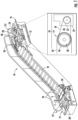
- the escalator system 201 includes balustrades 210 that each includes a skirt 211 with a brush 212 (see FIG. 5 ), a moving step 220 and an entrapment monitoring and detection system 230.
- the balustrades 210, each skirt 211 and each brush 212 are stationary.
- the moving step 220 is drivable to move in a conveyance direction C along the balustrades 210, each skirt 211 and each brush 212.
- the moving step 220 thus moves between the balustrades 210 to form step-skirt interfaces 240 (see FIG. 5 ) between ends of each brush 212 and corresponding sides 221 of the moving step 220 (see FIG.
- the entrapment monitoring and detection system 230 includes a sensor 231 for each step-skirt interface 240 and a processor 232. Each sensor 231 is disposed at or near to the corresponding step-skirt interface 240 and is configured to sense an object being present at the corresponding step-skirt interface 240 at any point along the corresponding balustrade 210/skirt 211/brush 212 that the sensor 231 is responsible for scanning.
- the sensor 231 at each step-skirt interface 240 can include multiple sensors 231 1 , 231 2 that sense in a same direction DS and/or multiple sensors 231 3 , 231 4 that sense in opposite directions DO 1 , DO 2 .
- the sensor 231 1 is responsible for sensing in the direction DS along the corresponding balustrade 210/skirt 21 1/brush 212 to a location of sensor 231 2 and the sensor 231 2 is responsible for sensing in the direction DS along the corresponding balustrade 210/skirt 211/brush 212 to a next sensor or to an end of the escalator.
- the sensors 231 3 , 231 4 about one another, the sensor 231 3 is responsible for sensing in the direction DO 1 along the corresponding balustrade 210/skirt 211/brush 212 and the sensor 231 4 is responsible for sensing in the direction DO 2 along the corresponding balustrade 210/skirt 211/brush 212. It is to be understood that other sensors arrangements are possible and that an escalator need not have a same sensor arrangement at each step-skirt interface 240.
- the processor 232 can be a component of the controller 115 of FIG. 1 and is operably coupled to the sensor 231 and includes a processing unit, a networking unit by which the processing unit is communicative with the sensor 231 and external devices and a memory.
- the memory has executable instructions stored thereon, which, when executed, cause the processing unit to operate as described herein. The following description will refer to the processor 232 generally.
- the processor 232 is configured to determine whether any sensor 231 senses the object being present at the step-skirt interface 240 for which that sensor 231 is responsible for scanning for a predetermined time. In addition, the processor 232 is further configured to judge that an entrapment incident is in effect in accordance with an affirmative determination that the sensor 231 senses the object being present at the step-skirt interface 240 for the predetermined time and to take a mitigation action accordingly.
- the mitigation action can include at least one or more of activating one or more local warning lights 501, which are arranged along one or both of the balustrades 210, to emit a first color (i.e., orange to denote a warning of a potential/imminent entrapment at the location of the warning light 501), activating the one or more local warning lights 501 to emit a second color (i.e., red to denote an alarm of a potential/imminent entrapment at the location of the warning light 501) and braking or slowing the escalator system (see FIG. 7 ) in an event of an entrapment incident being currently in effect.
- a first color i.e., orange to denote a warning of a potential/imminent entrapment at the location of the warning light 501
- a second color i.e., red to denote an alarm of a potential/imminent entrapment at the location of the warning light 501
- each sensor 231 can include or be provided as one or more of a light detection and ranging or a laser imaging, detection, and ranging (LiDAR) sensor, a radio detection and ranging (RADAR) sensor and/or a camera.
- LiDAR laser imaging, detection, and ranging
- RADAR radio detection and ranging
- each sensor 231 can be provided as one or more of a 2D LiDAR sensor, a millimeter wave RADAR sensor and/or a red, green, blue, depth (RGBD) camera.
- each sensor 231 can be provided as plural sensors as described above including a combination of one or more sensor types listed herein.
- the sensor 231 can be configured to execute periodic sensing and can be further configured to generate the data as signals S during the periodic sensing. These signals S can be receivable and readable by the processor 232.
- the sensor 231 can periodically scan its entrapment interface ten times per second, for example, as illustrated in FIG. 6 which shows a compilation of those multiple scans so the aspect of time varying signals is introduced.
- the signals S of that sensor 231 are first signals S 1 and are reflective of a length of scanning responsibility of that sensor 231 along the adjacent balustrade 210/skirt 211/brush 212.
- the signals S of that sensor 231 deviate from the first signals S 1 and persist as second signals S 2 for less than the predetermined time.
- the signals S of that sensor 231 deviate from the first signals S1 and persist as third signals S 3 for at least the predetermined time.
- the deviation of the second signals S 2 and the third signals S 3 from the first signals S 1 manifests as data points that are not reflective of the length of scanning responsibility of the corresponding sensor 231 along the adjacent balustrade 210/skirt 211/brush 212 but rather the shorter and variable distance between the sensor 231 and the object that is present at the step-skirt interface 240.
- the first signals S1, the second signals S2 and the third signals S3 relate to a moving frame, which moves relative to the sensor 231, which is static.
- a stationary object e.g., a shoe
- a stationary object e.g., a shoe
- the sensor is looking along an escalator that is moving in a direction away from it.
- "persistence" for entrapment detection would appear like the set of scans for the third signal S3 which as shown are moving away at the escalator running speed.
- the processor 232 can be trained or otherwise programmed to recognize the length of scanning responsibility of that sensor 231 along the adjacent balustrade 210/skirt 211/brush 212 reflected by the first signals S 1 , the second signals S 2 and the third signals S 3 using various types of training scenarios and modeling.
- the processor 232 can be trained or programmed to distinguish the third signals S 3 from the first signals S 1 and from the second signals S 2 to judge, from the third signals S 3 , that the entrapment incident is in effect and to subsequently take the mitigation action.
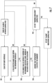
- a method of operating an entrapment monitoring and detection system of an escalator system in which a moving step passes by ends of a brush of a balustrade at a step-skirt interface includes scanning the step-skirt interface (block 701), determining whether results of the scanning are indicative of an object at the step-skirt interface (block 702), determining whether the results of the scanning are indicative of the object at the step-skirt interface persisting for a predetermined time (block 703) and judging that an entrapment is in effect or is imminent in accordance with the results of the scanning being indicative of the object at the step-skirt interface and persisting for the predetermined time (block 704).
- the method can also include taking a mitigation action to address the entrapment being in effect or imminent (block 705), such as by at least one or more of activating a warning light to emit a first color, activating the warning light to emit a second color and braking or slowing the escalator system.
- an example method of operating an entrapment monitoring and detection system of an escalator system in which a moving step passes by ends of a brush of a balustrade at a step-skirt interface is provided.
- the method includes two main components. The first is an object sensing and tracking component and the second is an entrapment identification and response component.
- the method includes scanning the step-skirt interface (block 801) and determining whether results of the scanning are indicative of an object at the step-skirt interface by showing that a detected range is less than a predefined scan length (block 802). If results of the determining of block 802 are negative, the method includes deleting an object reference and zeroing an object scan counter (block 803) whereupon control reverts to the scanning of block 801. If results of the determining of block 802 are affirmative, the method includes determining whether a new range is consistent with a prior identified object (block 804) taking into account the frame of reference in moving at the escalator running speed.
- the method includes redefining an object reference and resetting the object scan counter to one (block 805) whereupon control reverts to the scanning of block 801. If results of the determining of block 804 are affirmative, the method includes successively incrementing the object scan counter (block 806).
- the method includes determining whether the object scan counter has a value which is greater than N-action (block 807) and, if so, initiating an entrapment mitigation action (block 808), such as escalator shutdown.
- N-action is a value of the object scan counter that is predefined to be associated with an entrapment incident that needs to be mitigated. If not, the method further includes determining whether the object scan counter has a value which is greater than N-alarm (block 809) and, if so, sending out an alarm indication at a location of the object (block 810), such as a red alarm light being emitted by local LEDs, whereupon control reverts to the scanning of block 801.
- N-alarm is a value of the object scan counter that is predefined to be associated with an imminent or potential entrapment incident that may need to be mitigated in the near future but does not yet warrant escalator shutdown. If not, the method further includes determining whether the object scan counter has a value which is greater than N-warning (block 811) and, if so, sending out a warning indication at a location of the object (block 812), such as an orange warning light being emitted by the local LEDs, whereupon control reverts to the scanning of block 801.
- N-warning is a value of the object scan counter that is predefined to be associated with a slight potential for an entrapment incident that may need to be mitigated but does not yet warrant an alarm. If not, control reverts to the scanning of block 801.
- the three levels of the system response described above with reference to Fig. 8 in particular are an example illustration of one implementation of the method of detection. Alternate configurations with additional or fewer levels could also be used in such a detection system.
Landscapes
- Business, Economics & Management (AREA)
- Emergency Management (AREA)
- Physics & Mathematics (AREA)
- General Physics & Mathematics (AREA)
- Escalators And Moving Walkways (AREA)
Abstract
Description
- The present disclosure relates to escalator systems and, in particular, to a system and method that provide for LiDAR-based entrapment detection.
- Conveyors of people, such as escalators and moving walkways, usually include a conveyance band that moves with people standing on it between opposing landing zones, driving machines that drive movement of the conveyance band, combplates at each of the landing zones, balustrades on either side of the conveyance band and outer skirts. The conveyance band can be configured to form multiple moving steps that move between the opposing landing zones. Each of the moving steps can have a surface that includes cleats and grooves. The combplates are provided at the opposing landing zones. Each combplate includes teeth that extend into the grooves of the surface of the conveyance band as the conveyance band moves relative to each combplate and the cleats move along each of the teeth. The outer skirts are supported on the balustrades on either side of the conveyance band between the landing zones. The outer skirts are typically stationary relative to the moving steps.
- The interface between each of the moving steps and the stationary outer skirts on an escalator has long been a safety risk for entrapments due to the relative motion of the moving steps and the stationary outer skirts. One way to address but not necessarily solve this issue has been the use of brushes on the stationary outer skirts to make passengers aware of the potential for entrapment.
- Therefore, since the use of brushes does not solve the problem of entrapment between the moving steps of an escalator and the outer skirts, a need exists for a system and method that provide for detection of potential/imminent step-skirt entrapments and a focused and directed warning to avoid a true entrapment.
- According to an aspect of the disclosure, an escalator system is provided and includes a balustrade including a skirt with a brush, a moving step, which is drivable to move in a conveyance direction along the balustrade to form a step-skirt interface between ends of the brush of the skirt and a corresponding side of the moving step, and an entrapment monitoring and detection system. The entrapment monitoring and detection system includes a sensor and a processor. The sensor is disposed at the step-skirt interface and is configured to sense an object being present at the step-skirt interface. The processor is configured to determine whether the sensor senses the object being present at the step-skirt interface for a predetermined time.
- Particular embodiments may include any one, or a plurality, of the following optional features, alone or in combination with each other.
- In accordance with additional or alternative embodiments, the sensor includes multiple sensors that sense in a same direction or in multiple directions.
- In accordance with additional or alternative embodiments, the sensor is a LiDAR sensor.
- In accordance with additional or alternative embodiments, the sensor is a RADAR sensor.
- In accordance with additional or alternative embodiments, the sensor is a camera.
- In accordance with additional or alternative embodiments, the sensor is one or more of a LiDAR sensor, a RADAR sensor or a camera.
- In accordance with additional or alternative embodiments, the sensor is configured to execute periodic sensing and is further configured to generate signals during the periodic sensing which are receivable and readable by the processor. When no object is present at the step-skirt interface, the signals are first signals and are reflective of a predetermined length along the balustrade for which the sensor is responsible. When an object is present at the step-skirt interface for less than the predetermined time, the signals deviate from the first signals and persist for less than the predetermined time. When an object is present at the step-skirt interface for at least the predetermined time, the signals deviate from the first signals and persist for at least the predetermined time.
- In accordance with additional or alternative embodiments, the escalator system further includes light emitting diodes (LEDs) arranged along the balustrade and controllable by the entrapment monitoring and detection system to emit light in response to the processor determining that the sensor senses the object being present at the step-skirt interface for the predetermined time.
- In accordance with additional or alternative embodiments, the processor is further configured to judge that an entrapment incident is in effect or is imminent in accordance with an affirmative determination that the sensor senses the object being present at the step-skirt interface for the predetermined time and to take a mitigation action accordingly and the mitigation action includes at least one or more of activating a warning light to emit a first color, activating the warning light to emit a second color and braking or slowing the escalator system.
- According to an aspect of the disclosure, an escalator system is provided and includes balustrades, each including a skirt with a brush, a moving step, which is drivable to move in a conveyance direction between the balustrades to form step-skirt interfaces between ends of each brush and corresponding sides of the moving step, and an entrapment monitoring and detection system. The entrapment monitoring and detection system includes a sensor and a processor. The sensor is disposed at each step-skirt interface and is configured to sense an object being present at each step-skirt interface. The processor is configured to determine whether either sensor senses the object being present at either step-skirt interface for a predetermined time, to judge that an entrapment incident is in effect or is imminent in accordance with an affirmative determination that either sensor senses the object being present at either step-skirt interface for the predetermined time and to take a mitigation action accordingly.
- Particular embodiments may include any one, or a plurality, of the following optional features, alone or in combination with each other.
- In accordance with additional or alternative embodiments, the sensor at each step-skirt interface includes multiple sensors that sense in a same direction or in multiple directions.
- In accordance with additional or alternative embodiments, the sensor at each step-skirt interface is a LiDAR sensor.
- In accordance with additional or alternative embodiments, the sensor at each step-skirt interface is a RADAR sensor.
- In accordance with additional or alternative embodiments, the sensor at each step-skirt interface is a camera.
- In accordance with additional or alternative embodiments, the sensor at each step-skirt interface is one or more of a LiDAR sensor, a RADAR sensor or a camera.
- In accordance with additional or alternative embodiments, the sensor at each step-skirt interface is configured to execute periodic sensing and is further configured to generate signals during the periodic sensing which are receivable and readable by the processor. When no object is present at either step-skirt interface, the signals of each sensor are first signals and are reflective of a predetermined length along the balustrades for which each sensor is responsible. When an object is present at either step-skirt interface for less than the predetermined time, the signals of the corresponding sensor deviate from the first signals and persist for less than the predetermined time. When an object is present at either step-skirt interface for at least the predetermined time, the signals of the corresponding sensor deviate from the first signals and persist for at least the predetermined time.
- In accordance with additional or alternative embodiments, the escalator system further includes light emitting diodes (LEDs) arranged along each of the balustrades and controllable by the entrapment monitoring and detection system to emit light in response to the processor determining that the sensor senses the object being present at the step-skirt interface for the predetermined time.
- In accordance with additional or alternative embodiments, the processor is further configured to judge that an entrapment incident is in effect or is imminent in accordance with an affirmative determination that either sensor senses the object being present at the corresponding step-skirt interface for the predetermined time and to take a mitigation action accordingly and the mitigation action includes at least one or more of activating a warning light to emit a first color, activating the warning light to emit a second color and braking or slowing the escalator system.
- According to an aspect of the disclosure, a method of operating an entrapment monitoring and detection system of an escalator system in which a moving step passes by ends of a brush of a balustrade at a step-skirt interface is provided. The method includes scanning the step-skirt interface, determining whether results of the scanning are indicative of an object at the step-skirt interface, determining whether the results of the scanning are indicative of the object at the step-skirt interface persisting for a predetermined time and judging that an entrapment is in effect or imminent in accordance with the results of the scanning being indicative of the object at the step-skirt interface and persisting for the predetermined time.
- Particular embodiments may include any one, or a plurality, of the following optional features, alone or in combination with each other.
- In accordance with additional or alternative embodiments, the method further includes taking a mitigation action to address the entrapment being in effect or imminent and the mitigation action includes at least one or more of activating a warning light to emit a first color, activating the warning light to emit a second color and braking or slowing the escalator system.
- Additional features and advantages are realized through the techniques of the present disclosure. Other embodiments and aspects of the disclosure are described in detail herein and are considered a part of the claimed technical concept. For a better understanding of the disclosure with the advantages and the features, refer to the description and to the drawings.
- For a more complete understanding of this disclosure, reference is now made to the following brief description, taken in connection with the accompanying drawings and detailed description, wherein like reference numerals represent like parts:
-
FIG. 1 is a perspective view of an escalator system in accordance with embodiments; -
FIG. 2 is a schematic illustration of an escalator system having an entrapment monitoring and detection system in accordance with embodiments; -
FIG. 3 is a perspective view of an escalator system having an entrapment monitoring and detection system in accordance with embodiments; -
FIG. 4 is a top-down view of arrangements of sensors of the entrapment monitoring and detection system ofFIGS. 2 and 3 in accordance with embodiments; -
FIG. 5 is a perspective view of components of the entrapment monitoring and detection system ofFIGS. 2 and 3 in accordance with embodiments; -
FIG. 6 is a graphical depiction of an operation of the escalator system having the entrapment monitoring and detection system ofFIGS. 2-5 ; -
FIG. 7 is a flow diagram illustrating a method of operating an entrapment monitoring and detection system of an escalator system in accordance with embodiments; and -
FIG. 8 is a flow diagram illustrating a method of operating an entrapment monitoring and detection system of an escalator system in accordance with further embodiments. - In escalator technology, passenger safety risks are associated with riding on escalators. These include over-crowding that can cause riders to stumble and entrapments of personal items (e.g., shoes, laces or clothing items) at the interface of moving steps and the combplate and at the interface of the moving steps and outer skirts on balustrades at either side of escalators.
- Thus, as will be described below, a system and method are provided for detecting potential/imminent step-skirt entrapments and for focused and directed warning to avoid a true entrapment. An escalator is instrumented with light detection and ranging (LiDAR) sensors or other similar types of sensors on either side of the escalator. The sensors monitor straight portions of the escalator run. Multiple sensors may be used on each side to account for the potential of an entrapment case obstructing another entrapment further along the sensor focus area. Data, such as LiDAR data, would then be processed by a device to detect entrapment hazards by monitoring the range to the object and its persistence over time. This processing would result in the ability to display entrapment hazards at the moving location they are detected using, for example, a string of light emitting diodes (LEDS) where "yellow" would be a caution (object is first viewed in the step/skirt interface) and "red" would be an alarm (object persists over time, moving with the step). This caution/alarm could be displayed to the passenger and potentially used to drop the escalator brake (i.e., as a last resort).
- With reference to
FIG. 1 , anescalator 10 is provided. It should become apparent in the ensuing description that the invention is applicable to other passenger conveyor systems, such as moving walks. Theescalator 10 generally includes atruss 12 extending between alower landing 14 and anupper landing 16. A plurality of sequentially connected steps or treadplates 18 are connected to astep chain 20 and travel through a closed loop path within thetruss 12. A pair ofbalustrades 22 are disposed on either side of theescalator 10, with eachbalustrade 22 including a movinghandrail 24. Adrive machine 26, or drive system, is typically located in amachine space 28 under theupper landing 16. Anadditional machine space 28' can be located under thelower landing 14. Thedrive machine 26 is configured to drive thetread plates 18 and/orhandrails 24 through thestep chain 20. Thedrive machine 26 operates to move thetread plates 18 in a chosen direction at a desired speed under normal operating conditions. - The
tread plates 18 make a 180 degree heading change in a turn-aroundarea 19 located under thelower landing 14 and theupper landing 16. Thetread plates 18 are pivotally attached to thestep chain 20 and follow a closed loop path of thestep chain 20, running from one landing to the other, and back again. - The
drive machine 26 includes afirst drive member 32, such as a motor output sheave, connected to adrive motor 34 through abelt reduction assembly 36 including asecond drive member 38, such as an output sheave, driven by atension member 39, such as an output belt. Thefirst drive member 32 in some embodiments is a driving member, and thesecond drive member 38 is a driven member. - As used herein, the
first drive member 32 and/or thesecond drive member 38, in various embodiments, may be any type of rotational device, such as a sheave, pulley, gear, wheel, sprocket, cog, pinion, etc. Thetension member 39, in various embodiments, can be configured as a chain, belt, cable, ribbon, band, strip, or any other similar device that operatively connects two elements to provide a driving force from one element to another. For example, thetension member 39 may be any type of interconnecting member that extends between and operatively connects thefirst drive member 32 and asecond drive member 38. In some embodiments, as shown inFIG. 1 , thefirst drive member 32 and the second drive member may provide a belt reduction. For example,first drive member 32 may be approximately 75 mm (2.95 inches) in diameter while thesecond drive member 38 may be approximately 750 mm (29.53 inches) in diameter. The belt reduction, for example, allows the replacement of sheaves to change the speed for 50 or 60 Hz electrical supply power applications, or different step speeds. However, in other embodiments thesecond drive member 38 may be substantially similar to thefirst drive member 32. - As noted, the
first drive member 32 is driven bydrive motor 34 and thus is configured to drive thetension member 39 and thesecond drive member 38. In some embodiments thesecond drive member 38 may be an idle gear or similar device that is driven by the operative connection between thefirst drive member 32 and thesecond drive member 38 by means oftension member 39. Thetension member 39 travels around a loop set by thefirst drive member 32 and thesecond drive member 38, which herein after may be referred to as a small loop. The small loop is provided for driving a larger loop which consists of thestep chain 20, and is driven by anoutput sheave 40, for example. Under normal operating conditions, thetension member 39 and thestep chain 20 move in unison, based upon the speed of movement of thefirst drive member 32 as driven by thedrive motor 34. - The
escalator 10 also includes acontroller 115 that is in electronic communication with thedrive motor 34. Thecontroller 115 may be located, as shown, in themachine space 28 of theescalator 10 and is configured to control the operation of theescalator 10. For example, thecontroller 115 may provide drive signals to thedrive motor 34 to control the acceleration, deceleration, stopping, etc. of thetread plates 18 through thestep chain 20. Thecontroller 115 may be an electronic controller including a processor and an associated memory comprising computer-executable instructions that, when executed by the processor, cause the processor to perform various operations. The processor may be, but is not limited to, a single-processor or multiprocessor system of any of a wide array of possible architectures, including field programmable gate array (FPGA), central processing unit (CPU), application specific integrated circuits (ASIC), digital signal processor (DSP) or graphics processing unit (GPU) hardware arranged homogenously or heterogeneously. The memory may be but is not limited to a random access memory (RAM), read only memory (ROM), or other electronic, optical, magnetic or any other computer readable medium. - Although described herein as a particular escalator drive system and particular components, this is merely exemplary, and those of skill in the art will appreciate that other escalator system configurations may operate with the invention disclosed herein.
- With reference to
FIGS. 2-6 , anescalator system 201 is provided. Theescalator system 201 includesbalustrades 210 that each includes askirt 211 with a brush 212 (seeFIG. 5 ), a movingstep 220 and an entrapment monitoring anddetection system 230. Thebalustrades 210, eachskirt 211 and eachbrush 212 are stationary. The movingstep 220 is drivable to move in a conveyance direction C along thebalustrades 210, eachskirt 211 and eachbrush 212. The movingstep 220 thus moves between thebalustrades 210 to form step-skirt interfaces 240 (seeFIG. 5 ) between ends of eachbrush 212 and correspondingsides 221 of the moving step 220 (seeFIG. 5 ). The entrapment monitoring anddetection system 230 includes asensor 231 for each step-skirt interface 240 and aprocessor 232. Eachsensor 231 is disposed at or near to the corresponding step-skirt interface 240 and is configured to sense an object being present at the corresponding step-skirt interface 240 at any point along the correspondingbalustrade 210/skirt 211/brush 212 that thesensor 231 is responsible for scanning. - As shown in
FIG. 4 , thesensor 231 at each step-skirt interface 240 can includemultiple sensors multiple sensors sensor 2311 is responsible for sensing in the direction DS along the correspondingbalustrade 210/skirt 21 1/brush 212 to a location ofsensor 2312 and thesensor 2312 is responsible for sensing in the direction DS along the correspondingbalustrade 210/skirt 211/brush 212 to a next sensor or to an end of the escalator. In the latter case, thesensors sensor 2313 is responsible for sensing in the direction DO1 along the correspondingbalustrade 210/skirt 211/brush 212 and thesensor 2314 is responsible for sensing in the direction DO2 along the correspondingbalustrade 210/skirt 211/brush 212. It is to be understood that other sensors arrangements are possible and that an escalator need not have a same sensor arrangement at each step-skirt interface 240. - The
processor 232 can be a component of thecontroller 115 ofFIG. 1 and is operably coupled to thesensor 231 and includes a processing unit, a networking unit by which the processing unit is communicative with thesensor 231 and external devices and a memory. The memory has executable instructions stored thereon, which, when executed, cause the processing unit to operate as described herein. The following description will refer to theprocessor 232 generally. - The
processor 232 is configured to determine whether anysensor 231 senses the object being present at the step-skirt interface 240 for which thatsensor 231 is responsible for scanning for a predetermined time. In addition, theprocessor 232 is further configured to judge that an entrapment incident is in effect in accordance with an affirmative determination that thesensor 231 senses the object being present at the step-skirt interface 240 for the predetermined time and to take a mitigation action accordingly. In accordance with one or more alternative embodiments, the mitigation action can include at least one or more of activating one or morelocal warning lights 501, which are arranged along one or both of thebalustrades 210, to emit a first color (i.e., orange to denote a warning of a potential/imminent entrapment at the location of the warning light 501), activating the one or morelocal warning lights 501 to emit a second color (i.e., red to denote an alarm of a potential/imminent entrapment at the location of the warning light 501) and braking or slowing the escalator system (seeFIG. 7 ) in an event of an entrapment incident being currently in effect. - In accordance with embodiments, each
sensor 231 can include or be provided as one or more of a light detection and ranging or a laser imaging, detection, and ranging (LiDAR) sensor, a radio detection and ranging (RADAR) sensor and/or a camera. In accordance with further embodiments, eachsensor 231 can be provided as one or more of a 2D LiDAR sensor, a millimeter wave RADAR sensor and/or a red, green, blue, depth (RGBD) camera. In accordance with still further embodiments, eachsensor 231 can be provided as plural sensors as described above including a combination of one or more sensor types listed herein. - As shown in
FIG. 6 , which is illustrative of data that can be generated by thesensor 231, particularly where thesensor 231 is a LiDAR sensor, thesensor 231 can be configured to execute periodic sensing and can be further configured to generate the data as signals S during the periodic sensing. These signals S can be receivable and readable by theprocessor 232. In accordance with embodiments, thesensor 231 can periodically scan its entrapment interface ten times per second, for example, as illustrated inFIG. 6 which shows a compilation of those multiple scans so the aspect of time varying signals is introduced. When no object is present at the step-skirt interface 240 for asensor 231, the signals S of thatsensor 231 are first signals S1 and are reflective of a length of scanning responsibility of thatsensor 231 along theadjacent balustrade 210/skirt 211/brush 212. When an object is present at the step-skirt interface 240 for asensor 231 for less than the predetermined time, which could be anywhere in the range of milliseconds to seconds or longer, the signals S of thatsensor 231 deviate from the first signals S1 and persist as second signals S2 for less than the predetermined time. When an object is present at the step-skirt interface 240 for asensor 231 for at least the predetermined time, the signals S of thatsensor 231 deviate from the first signals S1 and persist as third signals S3 for at least the predetermined time. As used herein, the deviation of the second signals S2 and the third signals S3 from the first signals S1 manifests as data points that are not reflective of the length of scanning responsibility of thecorresponding sensor 231 along theadjacent balustrade 210/skirt 211/brush 212 but rather the shorter and variable distance between thesensor 231 and the object that is present at the step-skirt interface 240. Notably, the first signals S1, the second signals S2 and the third signals S3 relate to a moving frame, which moves relative to thesensor 231, which is static. A stationary object (e.g., a shoe) on the movingstep 220 will have an increasing distance from thesensor 231 if the sensor is looking along an escalator that is moving in a direction away from it. As such, "persistence" for entrapment detection would appear like the set of scans for the third signal S3 which as shown are moving away at the escalator running speed. - The
processor 232 can be trained or otherwise programmed to recognize the length of scanning responsibility of thatsensor 231 along theadjacent balustrade 210/skirt 211/brush 212 reflected by the first signals S1, the second signals S2 and the third signals S3 using various types of training scenarios and modeling. In particular, theprocessor 232 can be trained or programmed to distinguish the third signals S3 from the first signals S1 and from the second signals S2 to judge, from the third signals S3, that the entrapment incident is in effect and to subsequently take the mitigation action. - With reference to
FIG. 7 , a method of operating an entrapment monitoring and detection system of an escalator system in which a moving step passes by ends of a brush of a balustrade at a step-skirt interface. The method includes scanning the step-skirt interface (block 701), determining whether results of the scanning are indicative of an object at the step-skirt interface (block 702), determining whether the results of the scanning are indicative of the object at the step-skirt interface persisting for a predetermined time (block 703) and judging that an entrapment is in effect or is imminent in accordance with the results of the scanning being indicative of the object at the step-skirt interface and persisting for the predetermined time (block 704). In addition, the method can also include taking a mitigation action to address the entrapment being in effect or imminent (block 705), such as by at least one or more of activating a warning light to emit a first color, activating the warning light to emit a second color and braking or slowing the escalator system. - With reference to
FIG. 8 , an example method of operating an entrapment monitoring and detection system of an escalator system in which a moving step passes by ends of a brush of a balustrade at a step-skirt interface is provided. The method includes two main components. The first is an object sensing and tracking component and the second is an entrapment identification and response component. - As shown in
FIG. 8 , in the object sensing and tracking component, the method includes scanning the step-skirt interface (block 801) and determining whether results of the scanning are indicative of an object at the step-skirt interface by showing that a detected range is less than a predefined scan length (block 802). If results of the determining ofblock 802 are negative, the method includes deleting an object reference and zeroing an object scan counter (block 803) whereupon control reverts to the scanning ofblock 801. If results of the determining ofblock 802 are affirmative, the method includes determining whether a new range is consistent with a prior identified object (block 804) taking into account the frame of reference in moving at the escalator running speed. If results of the determining ofblock 804 are negative, the method includes redefining an object reference and resetting the object scan counter to one (block 805) whereupon control reverts to the scanning ofblock 801. If results of the determining ofblock 804 are affirmative, the method includes successively incrementing the object scan counter (block 806). - At this point, in the entrapment identification and response component, the method includes determining whether the object scan counter has a value which is greater than N-action (block 807) and, if so, initiating an entrapment mitigation action (block 808), such as escalator shutdown. Here, N-action is a value of the object scan counter that is predefined to be associated with an entrapment incident that needs to be mitigated. If not, the method further includes determining whether the object scan counter has a value which is greater than N-alarm (block 809) and, if so, sending out an alarm indication at a location of the object (block 810), such as a red alarm light being emitted by local LEDs, whereupon control reverts to the scanning of
block 801. Here, N-alarm is a value of the object scan counter that is predefined to be associated with an imminent or potential entrapment incident that may need to be mitigated in the near future but does not yet warrant escalator shutdown. If not, the method further includes determining whether the object scan counter has a value which is greater than N-warning (block 811) and, if so, sending out a warning indication at a location of the object (block 812), such as an orange warning light being emitted by the local LEDs, whereupon control reverts to the scanning ofblock 801. Here, N-warning is a value of the object scan counter that is predefined to be associated with a slight potential for an entrapment incident that may need to be mitigated but does not yet warrant an alarm. If not, control reverts to the scanning ofblock 801. - The three levels of the system response described above with reference to
Fig. 8 in particular are an example illustration of one implementation of the method of detection. Alternate configurations with additional or fewer levels could also be used in such a detection system. - Technical effects and benefits of the present disclosure are the provision of a fast-responding, retrofittable detection system that can monitor and detect entrapment hazards in escalators as the step/skirt interfaces. The system can be used to create a focused indication of the exact location of the detected entrapment hazard to give riding passengers a warning to avoid a true entrapment and could, if deemed useful, provide a signal to initiate a braking response.
- The corresponding structures, materials, acts and equivalents of all means or step plus function elements in the claims below are intended to include any structure, material, or act for performing the function in combination with other claimed elements as specifically claimed. The description of the present disclosure has been presented for purposes of illustration and description, but is not intended to be exhaustive or limited to the technical concepts in the form disclosed. Many modifications and variations will be apparent to those of ordinary skill in the art without departing from the scope and spirit of the disclosure. The embodiments were chosen and described in order to best explain the principles of the disclosure and the practical application and to enable others of ordinary skill in the art to understand the disclosure for various embodiments with various modifications as are suited to the particular use contemplated.
- While the preferred embodiments to the disclosure have been described, it will be understood that those skilled in the art, both now and in the future, may make various improvements and enhancements which fall within the scope of the claims which follow. These claims should be construed to maintain the proper protection for the disclosure first described.
Claims (14)
- An escalator system, comprising:a balustrade comprising a skirt with a brush;a moving step, which is drivable to move in a conveyance direction along the balustrade to form a step-skirt interface between ends of the brush of the skirt and a corresponding side of the moving step; andan entrapment monitoring and detection system comprising:a sensor disposed at the step-skirt interface and configured to sense an object being present at the step-skirt interface; anda processor configured to determine whether the sensor senses the object being present at the step-skirt interface for a predetermined time.
- The escalator system according to claim 1, wherein the sensor comprises multiple sensors that sense in a same direction or in multiple direction.
- The escalator system according to claim 1 or 2, wherein the sensor is one or more of a LiDAR sensor, a RADAR sensor or a camera.
- The escalator system according to any of claims 1 to 3, wherein:the sensor is configured to execute periodic sensing and is further configured to generate signals during the periodic sensing which are receivable and readable by the processor, andwherein:when no object is present at the step-skirt interface, the signals are first signals and are reflective of a predetermined length along the balustrade for which the sensor is responsible,when an object is present at the step-skirt interface for less than the predetermined time, the signals deviate from the first signals and persist for less than the predetermined time, andwhen an object is present at the step-skirt interface for at least the predetermined time, the signals deviate from the first signals and persist for at least the predetermined time.
- The escalator system according to any of claims 1 to 4, further comprising light emitting diodes (LEDs) arranged along the balustrade and controllable by the entrapment monitoring and detection system to emit light in response to the processor determining that the sensor senses the object being present at the step-skirt interface for the predetermined time.
- The escalator system according to any of claims 1 to 5, wherein:the processor is further configured to judge that an entrapment incident is in effect or is imminent in accordance with an affirmative determination that the sensor senses the object being present at the step-skirt interface for the predetermined time and to take a mitigation action accordingly, andthe mitigation action comprises at least one or more of activating a warning light to emit a first color, activating the warning light to emit a second color and braking or slowing the escalator system.
- The escalator system according to any of claims 1 to 6, comprising:balustrades, each comprising a skirt with a brush;the moving step being drivable to move in the conveyance direction between the balustrades to form step-skirt interfaces between ends of each brush and corresponding sides of the moving step; andwherein the entrapment monitoring and detection system comprises:a sensor disposed at each step-skirt interface and configured to sense an object being present at each step-skirt interface; andthe processor is configured to determine whether either sensor senses the object being present at either step-skirt interface for a predetermined time, to judge that an entrapment incident is in effect or is imminent in accordance with an affirmative determination that either sensor senses the object being present at either step-skirt interface for the predetermined time and to take a mitigation action accordingly.
- The escalator system according to claim 7, wherein the sensor at each step-skirt interface comprises multiple sensors that sense in a same direction or in multiple directions.
- The escalator system according to claim 7 or 8, wherein the sensor at each step-skirt interface is one or more of a LiDAR sensor, a RADAR sensor or a camera.
- The escalator system according to any of claims 7 to 9, wherein:the sensor at each step-skirt interface is configured to execute periodic sensing and is further configured to generate signals during the periodic sensing which are receivable and readable by the processor, andwherein:when no object is present at either step-skirt interface, the signals of each sensor are first signals and are reflective of a predetermined length along the balustrades for which each sensor is responsible,when an object is present at either step-skirt interface for less than the predetermined time, the signals of the corresponding sensor deviate from the first signals and persist for less than the predetermined time, andwhen an object is present at either step-skirt interface for at least the predetermined time, the signals of the corresponding sensor deviate from the first signals and persist for at least the predetermined time.
- The escalator system according to any of claims 7 to 10, further comprising light emitting diodes (LEDs) arranged along each of the balustrades and controllable by the entrapment monitoring and detection system to emit light in response to the processor determining that either sensor senses the object being present at the step-skirt interface for the predetermined time.
- The escalator system according to any of claims 7 to 11, wherein:the processor is further configured to judge that an entrapment incident is in effect or is imminent in accordance with an affirmative determination that either sensor senses the object being present at the corresponding step-skirt interface for the predetermined time and to take a mitigation action accordingly, andthe mitigation action comprises at least one or more of activating a warning light to emit a first color, activating the warning light to emit a second color and braking or slowing the escalator system.
- A method of operating an entrapment monitoring and detection system of an escalator system in which a moving step passes by ends of a brush of a balustrade at a step-skirt interface, the method comprising:scanning the step-skirt interface;determining whether results of the scanning are indicative of an object at the step-skirt interface;determining whether the results of the scanning are indicative of the object at the step-skirt interface persisting for a predetermined time; andjudging that an entrapment is in effect or imminent in accordance with the results of the scanning being indicative of the object at the step-skirt interface and persisting for the predetermined time.
- The method according to claim 13, further comprising taking a mitigation action to address the entrapment being in effect or imminent,
the mitigation action comprising at least one or more of activating a warning light to emit a first color, activating the warning light to emit a second color and braking or slowing the escalator system.
Applications Claiming Priority (1)
| Application Number | Priority Date | Filing Date | Title |
|---|---|---|---|
| US18/447,488 US20250051141A1 (en) | 2023-08-10 | 2023-08-10 | Escalator entrapment detection system |
Publications (1)
| Publication Number | Publication Date |
|---|---|
| EP4506292A1 true EP4506292A1 (en) | 2025-02-12 |
Family
ID=92259022
Family Applications (1)
| Application Number | Title | Priority Date | Filing Date |
|---|---|---|---|
| EP24193150.0A Pending EP4506292A1 (en) | 2023-08-10 | 2024-08-06 | Escalator entrapment detection system |
Country Status (3)
| Country | Link |
|---|---|
| US (1) | US20250051141A1 (en) |
| EP (1) | EP4506292A1 (en) |
| CN (1) | CN119460979A (en) |
Citations (4)
| Publication number | Priority date | Publication date | Assignee | Title |
|---|---|---|---|---|
| JP2008174315A (en) * | 2007-01-16 | 2008-07-31 | Mitsubishi Electric Corp | Safety device of passenger conveyor |
| US20180029837A1 (en) * | 2016-07-29 | 2018-02-01 | Otis Elevator Company | Sensor assembly, security system and passenger conveyor |
| US20190112160A1 (en) * | 2017-10-18 | 2019-04-18 | Otis Elevator Company | Balustrade for a people conveyor |
| US20200239283A1 (en) * | 2019-01-25 | 2020-07-30 | Kone Elevators Co., Ltd. | Safety apparatus for an escalator and an escalator comprising the safety apparatus |
Family Cites Families (15)
| Publication number | Priority date | Publication date | Assignee | Title |
|---|---|---|---|---|
| US4413719A (en) * | 1981-05-28 | 1983-11-08 | White Carl J | Method and apparatus for entrapment prevention and lateral guidance in passenger conveyor systems |
| US4669597A (en) * | 1985-11-04 | 1987-06-02 | Otis Elevator Company | Escalator skirt panel |
| JPH0812238A (en) * | 1994-06-30 | 1996-01-16 | Mitsubishi Denki Bill Techno Service Kk | Escalator safety and protection device |
| JPH09278337A (en) * | 1996-04-10 | 1997-10-28 | Otis Elevator Co | Safety device for person transfer device |
| US6405847B1 (en) * | 2000-07-06 | 2002-06-18 | Advancing Technologies | Deflector assembly for an escalator, walkway, or conveyor |
| DE202008003486U1 (en) * | 2008-03-12 | 2008-05-15 | Thyssenkrupp Fahrtreppen Gmbh | Safety device for an escalator |
| KR101413717B1 (en) * | 2008-12-04 | 2014-06-30 | 미쓰비시 덴키 빌딩 테크노 서비스 가부시키 가이샤 | Escalator safety device |
| BR112016013506B1 (en) * | 2013-12-20 | 2022-08-23 | Inventio Ag | ESCALATOR OR TREADMILL, HAVING TWO AREAS OF ACCESS AND A METHOD FOR OPERATING ESCALATOR OR TREADMILL, HAVING TWO AREAS OF ACCESS |
| JP6310875B2 (en) * | 2015-03-17 | 2018-04-11 | 株式会社日立製作所 | Passenger conveyor |
| CN107662875B (en) * | 2016-07-29 | 2021-07-06 | 奥的斯电梯公司 | Monitoring and detecting of engagement state of step and comb plate of passenger conveyor |
| CN106629366B (en) * | 2016-11-29 | 2018-06-26 | 广东省特种设备检测研究院珠海检测院 | A kind of escalator step measures and hidden danger alignment system and its method with skirt panel safety clearance |
| WO2020136513A1 (en) * | 2018-12-24 | 2020-07-02 | Mtr Corporation Limited | Detecting object on escalator or moving walkway |
| WO2020245942A1 (en) * | 2019-06-05 | 2020-12-10 | 三菱電機株式会社 | Passenger conveyor safety device |
| US11192757B2 (en) * | 2020-05-06 | 2021-12-07 | Techdayafter, Inc. | Method and system for ensuring social distancing on an escalator or travellator |
| EP4164979B1 (en) * | 2020-06-16 | 2025-05-14 | KONE Corporation | People mover |
-
2023
- 2023-08-10 US US18/447,488 patent/US20250051141A1/en active Pending
-
2024
- 2024-08-06 EP EP24193150.0A patent/EP4506292A1/en active Pending
- 2024-08-09 CN CN202411089896.5A patent/CN119460979A/en active Pending
Patent Citations (5)
| Publication number | Priority date | Publication date | Assignee | Title |
|---|---|---|---|---|
| JP2008174315A (en) * | 2007-01-16 | 2008-07-31 | Mitsubishi Electric Corp | Safety device of passenger conveyor |
| JP4967672B2 (en) * | 2007-01-16 | 2012-07-04 | 三菱電機株式会社 | Passenger conveyor safety device |
| US20180029837A1 (en) * | 2016-07-29 | 2018-02-01 | Otis Elevator Company | Sensor assembly, security system and passenger conveyor |
| US20190112160A1 (en) * | 2017-10-18 | 2019-04-18 | Otis Elevator Company | Balustrade for a people conveyor |
| US20200239283A1 (en) * | 2019-01-25 | 2020-07-30 | Kone Elevators Co., Ltd. | Safety apparatus for an escalator and an escalator comprising the safety apparatus |
Non-Patent Citations (1)
| Title |
|---|
| DATABASE WPI Week 200856, Derwent World Patents Index; AN 2008-J61646 * |
Also Published As
| Publication number | Publication date |
|---|---|
| US20250051141A1 (en) | 2025-02-13 |
| CN119460979A (en) | 2025-02-18 |
Similar Documents
| Publication | Publication Date | Title |
|---|---|---|
| JP7024046B1 (en) | Diagnostic system | |
| CN109476464B (en) | Operation Abnormality Detection Device of Passenger Conveyor and Operation Abnormality Detection Method of Passenger Conveyor | |
| JP2014061966A (en) | Passenger conveyor | |
| US20250051141A1 (en) | Escalator entrapment detection system | |
| CN111320064B (en) | Passenger conveyor | |
| JP6222874B1 (en) | Passenger conveyor | |
| CN210150558U (en) | Passenger conveyor | |
| EP4541751A1 (en) | Escalator entrapment detection system | |
| CN112061944B (en) | Control method of passenger conveyor | |
| US20250042698A1 (en) | Comb plate for conveyor device, and conveyor device | |
| JP5567064B2 (en) | Passenger counting device for passenger conveyor | |
| JP5951664B2 (en) | Passenger conveyor equipment | |
| CN103803392B (en) | Passenger conveyors | |
| JP7309970B1 (en) | Passenger conveyor system and passenger conveyor | |
| US20250059004A1 (en) | Escalator combplate retraction device | |
| EP4506294A1 (en) | System for detecting broken combplate teeth of an escalator | |
| US20250059005A1 (en) | Automatic conveyor device | |
| US20250206574A1 (en) | Method for controlling a conveyor, controlling device, and conveyor | |
| US20250033934A1 (en) | Brake system for a conveyor system, method for detecting a brake of a conveyor system, and controller | |
| CN114132821A (en) | Long article monitoring system for man-carrying conveyor | |
| EP4509454A1 (en) | Automatic conveyor device | |
| EP4164979B1 (en) | People mover | |
| JP7540854B1 (en) | Passenger conveyor systems and moving objects | |
| JP7631421B2 (en) | Passenger conveyor tooth skipping detection device | |
| CN211141262U (en) | Automatic staircase |
Legal Events
| Date | Code | Title | Description |
|---|---|---|---|
| PUAI | Public reference made under article 153(3) epc to a published international application that has entered the european phase |
Free format text: ORIGINAL CODE: 0009012 |
|
| STAA | Information on the status of an ep patent application or granted ep patent |
Free format text: STATUS: THE APPLICATION HAS BEEN PUBLISHED |
|
| AK | Designated contracting states |
Kind code of ref document: A1 Designated state(s): AL AT BE BG CH CY CZ DE DK EE ES FI FR GB GR HR HU IE IS IT LI LT LU LV MC ME MK MT NL NO PL PT RO RS SE SI SK SM TR |
|
| STAA | Information on the status of an ep patent application or granted ep patent |
Free format text: STATUS: REQUEST FOR EXAMINATION WAS MADE |
|
| 17P | Request for examination filed |
Effective date: 20250711 |
|
| STAA | Information on the status of an ep patent application or granted ep patent |
Free format text: STATUS: EXAMINATION IS IN PROGRESS |
|
| 17Q | First examination report despatched |
Effective date: 20251217 |
|
| GRAP | Despatch of communication of intention to grant a patent |
Free format text: ORIGINAL CODE: EPIDOSNIGR1 |
|
| STAA | Information on the status of an ep patent application or granted ep patent |
Free format text: STATUS: GRANT OF PATENT IS INTENDED |