EP4506270A1 - Forming unit for forming sealed packs containing a pourable product and method for forming sealed packs containing a pourable product - Google Patents
Forming unit for forming sealed packs containing a pourable product and method for forming sealed packs containing a pourable product Download PDFInfo
- Publication number
- EP4506270A1 EP4506270A1 EP24184214.5A EP24184214A EP4506270A1 EP 4506270 A1 EP4506270 A1 EP 4506270A1 EP 24184214 A EP24184214 A EP 24184214A EP 4506270 A1 EP4506270 A1 EP 4506270A1
- Authority
- EP
- European Patent Office
- Prior art keywords
- tube
- cam profile
- forming
- along
- movable cam
- Prior art date
- Legal status (The legal status is an assumption and is not a legal conclusion. Google has not performed a legal analysis and makes no representation as to the accuracy of the status listed.)
- Pending
Links
Images




Classifications
-
- B—PERFORMING OPERATIONS; TRANSPORTING
- B65—CONVEYING; PACKING; STORING; HANDLING THIN OR FILAMENTARY MATERIAL
- B65B—MACHINES, APPARATUS OR DEVICES FOR, OR METHODS OF, PACKAGING ARTICLES OR MATERIALS; UNPACKING
- B65B9/00—Enclosing successive articles, or quantities of material, e.g. liquids or semiliquids, in flat, folded, or tubular webs of flexible sheet material; Subdividing filled flexible tubes to form packages
- B65B9/10—Enclosing successive articles, or quantities of material, in preformed tubular webs, or in webs formed into tubes around filling nozzles, e.g. extruded tubular webs
- B65B9/20—Enclosing successive articles, or quantities of material, in preformed tubular webs, or in webs formed into tubes around filling nozzles, e.g. extruded tubular webs the webs being formed into tubes in situ around the filling nozzles
- B65B9/2049—Package shaping devices acting on filled tubes prior to sealing the filling opening
-
- B—PERFORMING OPERATIONS; TRANSPORTING
- B65—CONVEYING; PACKING; STORING; HANDLING THIN OR FILAMENTARY MATERIAL
- B65B—MACHINES, APPARATUS OR DEVICES FOR, OR METHODS OF, PACKAGING ARTICLES OR MATERIALS; UNPACKING
- B65B65/00—Details peculiar to packaging machines and not otherwise provided for; Arrangements of such details
- B65B65/02—Driving gear
-
- B—PERFORMING OPERATIONS; TRANSPORTING
- B65—CONVEYING; PACKING; STORING; HANDLING THIN OR FILAMENTARY MATERIAL
- B65B—MACHINES, APPARATUS OR DEVICES FOR, OR METHODS OF, PACKAGING ARTICLES OR MATERIALS; UNPACKING
- B65B51/00—Devices for, or methods of, sealing or securing package folds or closures; Devices for gathering or twisting wrappers, or necks of bags
- B65B51/10—Applying or generating heat or pressure or combinations thereof
- B65B51/26—Devices specially adapted for producing transverse or longitudinal seams in webs or tubes
- B65B51/30—Devices, e.g. jaws, for applying pressure and heat, e.g. for subdividing filled tubes
- B65B51/306—Counter-rotating devices
-
- B—PERFORMING OPERATIONS; TRANSPORTING
- B65—CONVEYING; PACKING; STORING; HANDLING THIN OR FILAMENTARY MATERIAL
- B65B—MACHINES, APPARATUS OR DEVICES FOR, OR METHODS OF, PACKAGING ARTICLES OR MATERIALS; UNPACKING
- B65B9/00—Enclosing successive articles, or quantities of material, e.g. liquids or semiliquids, in flat, folded, or tubular webs of flexible sheet material; Subdividing filled flexible tubes to form packages
- B65B9/10—Enclosing successive articles, or quantities of material, in preformed tubular webs, or in webs formed into tubes around filling nozzles, e.g. extruded tubular webs
- B65B9/20—Enclosing successive articles, or quantities of material, in preformed tubular webs, or in webs formed into tubes around filling nozzles, e.g. extruded tubular webs the webs being formed into tubes in situ around the filling nozzles
- B65B9/207—Enclosing successive articles, or quantities of material, in preformed tubular webs, or in webs formed into tubes around filling nozzles, e.g. extruded tubular webs the webs being formed into tubes in situ around the filling nozzles the web advancing continuously
Definitions
- the present invention relates to a forming unit for forming sealed packs containing a pourable product, preferably a pourable food product, from a tube formed from a web of packaging material.
- the present invention refers, without loss of generality, to a forming unit which is part of a packaging apparatus configured to produce sealed and folded packages containing a pourable product.
- the present invention also relates to a method for forming sealed packs containing a pourable product, preferably a pourable food product, from a tube formed from a web of packaging material.
- pourable food products such as fruit juice, UHT (ultra-high temperature-treated) milk, wine, tomato sauce, etc.
- UHT ultra-high temperature-treated milk
- wine tomato sauce
- etc. are sold in packages made of sterilized packaging material.
- a typical example is the parallelepiped-shaped package for pourable food products known as Tetra Brik Aseptic (registered trademark), which is made by folding and sealing a laminated web of packaging material.
- the packaging material has a multilayer structure comprising a base layer, e.g. made of paper, covered on both sides with layers of heat-seal plastic material, e.g. polyethylene.
- the packaging material also comprises a layer of oxygen-barrier material, e.g. an aluminum foil, which is superimposed on a layer of heat-seal plastic material, and is in turn covered with another layer of heat-seal plastic material forming the inner face of the package eventually contacting the food product.
- a layer of oxygen-barrier material e.g. an aluminum foil
- Packages of this sort are normally produced on fully automatic packaging apparatuses, which form and fill the packages starting from a multilayer web of packaging material.
- a continuous tube is formed from the web of packaging material which is initially wound in a reel and fed through a plurality of unwinding rollers.
- the web of packaging material is typically sterilized in the packaging apparatus, e.g. by applying a chemical sterilizing agent, such as hydrogen peroxide solution, which, once sterilization is completed, is removed from the surfaces of the packaging material, e.g. evaporated by heating.
- a chemical sterilizing agent such as hydrogen peroxide solution
- the tube In order to perform the package forming operations, the tube is continuously fed along a first direction, normally a straight vertical direction, is filled with the sterilized food product from above and is formed, sealed and subsequently cut along equally spaced transversal cross-sections extending along a second direction, normally a direction orthogonal to the first direction.
- So-called pillow packs are obtained thereby, which have a longitudinal sealing band, a top transversal sealing band and a bottom transversal sealing band.
- a packaging apparatus of such type is known from WO-A-2022017745 .
- Such packaging apparatus comprises a plurality of jaw units and a conveyor device (normally a chain conveyor) for advancing the jaw units.
- Each jaw unit comprises:
- each jaw unit includes two jaw members, each jaw members including a forming member and a sealing member.
- the conveyor device is configured to advance each jaw member along a respective closed-loop path, which includes one operative section, along which the respective forming member and sealing member interact with the tube, and one return section.
- the sealing member is arranged operatively downstream of the forming member, with respect to the first direction.
- a typical pair of forming members comprises two internally shaped half-shells, arranged at opposite lateral sides of the tube facing one another and configured to cyclically engage the tube from opposite lateral sides thereof, so as to surround successive portions of the tube to sequentially impart or transfer the predetermined external shape to these portions.
- a typical pair of sealing members comprises a seal element and a counterseal element (typically in the form of clamps), arranged at opposite lateral sides of the tube facing one another and which are configured to cyclically engage the tube in a clamping manner from opposite lateral sides thereof, so as to repeatedly seal the tube at the aforementioned cross-sections (according to a manner known).
- a seal element and a counterseal element typically in the form of clamps
- each jaw unit also comprises a cutting element, carried by one of the sealing element and countersealing element, for repeatedly interacting with the tube to cut the tube along the previously created sealing band.
- the obtained pillow packs are separated from one another at the respective transversal sealing bands.
- the forming members and the sealing members are cyclically moved along a third direction orthogonal to the first direction and the second direction, i.e. towards and away from the tube.
- the packaging apparatus further comprises a cam system for controlling the movement of the forming members towards and away from the tube.
- the cam system includes cam profiles, which are opportunely shaped for allowing the engagement and disengagement of the tube at the appropriate positions, and a plurality of cam followers or rollers, whereby at least one roller is integrally carried by each forming member.
- the tube Due to the downward advancement of the forming members and the sealing members along the first direction, by means of the chain conveyor, and due to the interaction of the forming members and especially of the sealing members with the tube, the tube is drawn downwards and fed along the first direction.
- each jaw member is advanced along the respective return section and then back to its respective operative section to be ready to interact again with the corresponding jaw member of the same jaw unit and with another subsequent portion of the tube (i.e. to form and seal another pillow pack).
- the so-obtained pillow packs are then directed to a folding unit of the packaging apparatus for the final folding thereof, thereby obtaining fully-folded finished packages containing pourable product.
- each jaw unit is controllable in at least:
- any significant contact between the forming member and the tube is avoided, even though the respective jaw member is advanced by the conveyor device.
- the filling level of the tube i.e. the measure of the volume of the pourable product present within the tube
- the aforementioned cam system for controlling the movement of the forming members includes a pair of fixed cam profiles and a respective pair of movable cam profiles, wherein each movable cam profile is movably mounted to the respective fixed cam profile.
- the cam system further includes an adjusting assembly for adjusting a position of each movable cam profile relatively to the respective fixed cam profile.
- each movable cam profile is adjustable between a first limit position and a second limit position, with respect to the relative fixed cam profile.
- first limit position the movable cam profiles are in a position approached to one another
- second limit position the movable cam profiles are in a position withdrawn from one another.
- the forming members When the rollers of the forming members interact with the movable cam profiles in their second limit positions, the forming members are spaced apart from the tube notwithstanding the advancement of the respective jaw along the first direction and the movement of the forming members along the third direction. In other words, the forming members do not reach the tube.
- the movable cam profiles follow an arc-shaped trajectory, thereby roto-translating.
- rollers carried by the forming members are configured to cyclically interact, due to the advancement of the respective jaw members along their respective closed-loop paths, partly with the fixed cam profile and partly with the movable cam profile.
- a transition area between each fixed cam profile and the respective movable cam profile can be identified, through which transition area each roller is configured to cyclically pass.
- number 1 indicates as a whole a non-limiting example of a packaging apparatus for producing a plurality of packages 2a containing a pourable product, preferably a pourable food product such as pasteurized or UHT milk, water, fruit juice, wine, peas, beans, etc.
- a pourable food product such as pasteurized or UHT milk, water, fruit juice, wine, peas, beans, etc.
- packaging apparatus 1 is configured to form, seal and fold packages 2a starting from a tube 3 of packaging material.
- the packaging material has a multilayer structure (not shown), and comprises a layer of fibrous material, e.g. paper, covered on both sides with respective layers of heat-seal plastic material, e.g. polyethylene.
- a layer of fibrous material e.g. paper
- heat-seal plastic material e.g. polyethylene
- the packaging material also comprises a layer of gas-and-light barrier material, e.g. aluminum foil or ethylene vinyl alcohol (EVOH) film, which is superimposed on a layer of heat-seal plastic material, and is in turn covered with another layer of heat-seal plastic material, the latter forming the inner face of package 2a eventually contacting the pourable product.
- gas-and-light barrier material e.g. aluminum foil or ethylene vinyl alcohol (EVOH) film
- the packaging material is initially provided in form of a web 4.
- the packaging apparatus 1 comprises:
- forming unit 6 has a central axis X along which tube 3 is fed, in use.
- Central axis X is parallel to a first direction A, which preferably is a straight vertical direction.
- tube 3 is fed along first direction A, downwards, and while being filled from above is formed and sealed by forming unit 6.
- Packaging apparatus 1 further comprises a folding unit (known per se and not shown) for folding the pillow packs 2, thereby obtaining packages 2a, according to a manner known and not described in detail.
- a folding unit (known per se and not shown) for folding the pillow packs 2, thereby obtaining packages 2a, according to a manner known and not described in detail.
- packaging apparatus 1 is configured to form and seal a plurality of pillow packs 2 containing the pourable product starting from web 4 and tube 3 and then to fold the pillow packs 2 for obtaining the aforementioned formed, sealed and folded packages 2a containing the pourable product.
- Forming unit 6 comprises at least one pair of forming members 8, known for example from WO-A-2022017745 , which are arranged on opposite lateral sides of axis X (and therefore, in use, of tube 3) and which are configured to cyclically engage successive longitudinal portions of tube 3 for the forming thereof.
- each forming member 8 includes an internally shaped half-shell configured to cyclically interact in contact with tube 3 for imprinting its shape thereon.
- forming members 8 are movable towards and away from one another and from tube 3 along a second direction B transversal to first direction A, and in particular orthogonal to first direction A, for cyclically surrounding and engaging tube 3 and forming tube 3 at the successive portions.
- forming unit 6 also includes at least one pair of sealing members 10 (e.g. a sealing element and a countersealing element) arranged at opposite lateral sides of axis X and which are configured to cyclically engage tube 3 at the equally spaced cross-sections in a clamping manner, so as to define transversal sealing bands on tube 3.
- sealing members 10 e.g. a sealing element and a countersealing element
- each portion of tube 3 is longitudinally delimited by a pair of successive sealing bands.
- forming unit 6 comprises a plurality of forming and sealing jaw units (known from WO-A-2022017745 ), each forming and sealing jaw unit comprising a pair of forming members 8 and a pair of sealing members 10; and
- each forming and sealing jaw unit includes two jaw members associated with one another, each jaw member including one forming member 8 and one sealing member 10.
- the conveyor device is configured to advance each jaw member along a respective closed-loop path, which includes one operative section, along which the respective forming member 8 and sealing member 10 interact with tube 3, and one return section, according to the same configuration known from WO-A-2022017745 .
- sealing member 10 is arranged operatively downstream of forming member 8, with respect to the advancement direction of the jaw member along the respective closed-loop path.
- forming members 8 and sealing members 10 are cyclically carried by the conveyor device along the respective operative sections and along first direction A to cyclically and repeatedly engage the successive portions of tube 3, and then along the respective return sections.
- Tube 3 is drawn (downwards) along first direction A in a known manner, due to the advancement of forming members 8 and sealing members 10 along first direction A carried by the respective forming and sealing jaw unit, and due to the interaction of forming members 8 and of sealing members 10 with tube 3.
- each forming and sealing jaw unit also comprises a cutting member (not shown), carried by one of the sealing members 10, for repeatedly interacting with tube 3 to cut tube 3 along the previously created sealing band, once the respective tube portion is formed.
- the obtained pillow packs 2 are separated from one another at the respective transversal sealing bands.
- forming members 8 and sealing members 10 are movable along second direction B, i.e. towards and away from tube 3, towards and away from axis X and towards and away from one another, while being advanced along the respective operative sections by the conveyor device.
- Forming unit 6 comprises a cam system 11 for controlling the movement of forming members 8 along second direction B.
- cam system 11 is configured to cyclically drive a movement of forming members 8 along second direction B towards and away from axis X, towards and away from one another and, in use, towards and away from tube 3.
- cam system 11 comprises:
- each forming member 8 integrally carries at least one roller 15 (or cam follower) which is configured to cooperate in rolling contact with the respective cam assembly 12, i.e. with the respective fixed cam profile 13 and movable cam profile 14, so as to determine the movement of such forming member 8 along second direction B, while such forming member 8 is conveyed along first direction A by the conveyor device.
- roller 15 or cam follower
- the movement of forming members 8 along second direction B driven by the interaction of rollers 15 with movable cam profiles 14 may be a composite movement including a translational component and an angular or rotational component.
- rollers 15 are configured to be advanced, by means of the respective forming and sealing jaw units and thus by means of the conveyor device, along a respective path S, which follows the contour of fixed cam profile 13 and movable cam profile 14 of such cam assembly 12, and which at least partially corresponds to or follows the respective aforementioned closed-loop path, as visible in Figure 2 .
- Figure 2 only shows part of the two paths S.
- paths S are preferably endless and extend along a closed-loop trajectory, following the respective closed-loop paths of the jaw members.
- Each path S comprises an operative portion S1, extending along the respective movable cam profile 14.
- operative portion S1 extending along the respective movable cam profile 14.
- the movement of forming members 8 towards and away from tube 3 may be a composite movement including a translational component and an angular or rotational component.
- movable cam profiles 14 are opportunely shaped for allowing the movement of forming members 8 towards and away from tube 3, i.e. the engagement and disengagement of tube 3 at the appropriate positions, according to a manner known and not described in detail.
- movable cam profile 14 is movably coupled to fixed cam profile 13 and is movable towards and away from axis X (and in use from tube 3) between a retracted position (represented in continuous lines in Figure 3 and shown in Figure 6b ) and an extracted position (represented in dashed lines in Figure 3 and shown in Figure 6a ) with respect to the axis X.
- movable cam profile 14 is also movable, and may be arranged, in a virtually infinite number of intermediate positions between the retracted position and the extracted position.
- forming unit 6 comprises an adjusting assembly 16 for adjusting the position of movable cam profiles 14 between the retracted position and the extracted position (and in any one of the aforementioned intermediate positions).
- adjusting assembly 16 is configured to drive the movement of movable cam profiles 14 between the retracted position and the extracted position (and in any one of the aforementioned intermediate positions).
- adjusting assembly 16 comprises:
- the transmission system 18 may comprise a main shaft 18a, coupled to actuator 17 for receiving torque and motion therefrom, and two control bars 18b each coupled to one movable cam profile 14.
- actuator 17 is configured to drive a rotation of control bars 18b for moving movable cam profiles 14 between the retracted position and the extracted position.
- each movable cam profile 14 is movable between a first limit position approached to axis X (and in use to tube 3) and corresponding to the extracted position, and a second limit position withdrawn from axis X (and in use from tube 3) and corresponding to the retracted position.
- the first limit position corresponds to a position in which forming members 8 are the closest to axis X (and tube 3).
- the second limit position corresponds to a position in which forming members 8 are the farthest from axis X (and tube 3).
- the intermediate positions are comprised between such first limit position and such second limit position.
- movable cam profiles 14 are selectively controllable in:
- forming unit 6 is configured so that when movable cam profiles 14 are controlled in their second limit positions, forming members 8 do not reach tube 3 during their movement along second direction B driven by cam assemblies 12, and while advancing along first direction A driven by the conveyor device.
- any significant contact between forming members 8 and tube 3 is avoided, even though the respective forming and sealing jaw unit is advanced by the conveyor device.
- the filling level of tube 3 i.e. the measure of the volume of the pourable product present within tube 3
- forming unit 6 may comprise a control unit configured to automatically control the movement of movable cam profiles 14 depending on the operative conditions of packaging apparatus 1.
- movable cam profiles 14 are controlled between their first limit positions (i.e. their extracted positions) and their second limit positions (i.e. their retracted positions.
- movable cam profiles 14 may be arranged in any of the intermediate positions, i.e. in any of the position interposed between the first limit position and the second limit position, so as to control the interaction of forming members 8 with tube 3.
- each cam assembly 12 comprises a guiding device 19 configured to constrain movable cam profile 14 to move parallel to second direction B between the retracted position and the extracted position (i.e. in its movement towards and away from axis X or, in use, tube 3).
- each guiding device 19 is configured to guide the respective movable cam profile 14 so that the movement of such movable cam profile 14 between the extracted position and the retracted position is a pure translation along second direction B.
- each guiding device 19 is configured to produce a pure translational movement of the respective movable cam profile 14 exclusively along second direction B.
- cam assemblies 12 are arranged facing one another, and in particular movable cam profiles 14 are arranged facing one another.
- movable cam profiles 14 are simultaneously movable towards and away from one another between their retracted positions and extracted positions (and their respective intermediate positions).
- guiding devices 19 are configured to force the simultaneous movement of movable cam profiles 14 towards and away from one another to occur exclusively along second direction B.
- guiding device 19 comprises a guide element 20 integral to one of the fixed cam profile 13 and the movable cam profile 14, in the example shown integral to the fixed cam profile 13, and a slide element 21 integral to the other one of the fixed cam profile 13 and the movable cam profile 14, in the example shown integral to the movable cam profile 14.
- Slide element 21 is slidably coupled to guide element 20 and is configured to slide along guide element 20 during the movement of movable cam profile 14 between its retracted position and its extracted position.
- guide element 20 extends parallel to second direction B, thereby determining a translational movement of slide element 21 exclusively along second direction B and constraining slide element 21 to move exclusively along second direction B.
- guiding devices 19 are part of adjusting assembly 16, since they contribute to the movement of movable cam profiles 14.
- a transition area T is defined between fixed cam profile 13 and movable cam profile 14 ( Figures 4 , 5 and 6a , 6b ).
- each roller 15, carried in motion by the conveyor device is configured to cyclically interact, due to the cyclical advancement of the respective jaw members, partly with fixed cam profile 13 and partly with movable cam profile 14.
- each cam assembly 12 comprises a transition area T for rollers 15 defined partly by fixed cam profile 13 and partly by movable cam profile 14 and onto which transition area T each roller 15 is configured to cyclically pass for transiting from fixed cam profile 13 to movable cam profile 14.
- transmission system 18 comprises, for each cam assembly 12, a main eccentric 22 coupled to actuator 17 and an elongated slot 23 obtained in movable cam profile 14.
- main eccentric 22 engages elongated slot 23 in a sliding manner and is configured to slide within and along elongated slot 23 for transmitting the motion from actuator 17 to the respective movable cam profile 14.
- each elongated slot 23 extends along first direction A, so that main eccentric 22 is freely movable within elongated slot 23 along first direction A.
- main eccentric 22 has a size smaller than the total extension of slot 23 along first direction A. That is, main eccentric 22 is completely contained in slot 23.
- main eccentric 22 does not completely fill slot 23, but instead is free to slidingly move therein, along first direction A.
- This configuration allows for maintaining substantially the same structural configuration of forming unit 6 and adjusting assembly 16 as the one described in WO-A-2022017745 , only adapting it for the pure translational movement of movable cam profiles 14 along second direction B according to the present invention.
- the forming unit 6 according to the present invention can be easily implemented and obtained with little effort and minimum architectural and design modifications.
- transmission system 18 further comprises, for each cam assembly 12, a further elongated slot 24 obtained in movable cam profile 14, an auxiliary eccentric 25 engaging further elongated slot 24 and configured to slide along further elongated slot 24, and a lever mechanism 26 integrally coupling main eccentric 22 with auxiliary eccentric 25 and configured to transmit the motion from main eccentric 22 to auxiliary eccentric 25.
- Elongated slot 24 substantially corresponds, in shape and function, to elongated slot 23, and auxiliary eccentric 25 substantially corresponds, in shape and function, to main eccentric 22.
- main eccentric 22 and auxiliary eccentric 25 are configured to simultaneously push the respective movable cam profile 14 during their sliding within elongated slot 23 and further elongated slot 24, respectively, thereby driving movable cam profile 14 between its retracted position and its extracted position.
- lever mechanism 26 is a sort of four-bar linkage, wherein the two hinge constraints are defined by main eccentric 22 and auxiliary eccentric 25, and wherein such hinge constraints are free to move along first direction A within the respective elongated slots 23, 24.
- the terminal section of fixed cam profile 13 and the initial section of movable cam profile 14, which together define transition area T remain parallel to one another (and to second direction B), and preferably coplanar with one another.
- first direction A is preferably vertical and second direction B is preferably orthogonal to first direction A
- transition area T is horizontal, with respect to the direction of gravity.
- forming unit 6 allows to implement a method for forming a plurality of packs 2 containing a pourable product from a tube 3 of packaging material, the method comprising the steps of:
- transition area T is parallel to second direction B.
- elongated slot 23 and of main eccentric 22 slidable therein allows for maintaining substantially the same structural configuration of forming unit 6 and adjusting assembly 16 as the one described in WO-A-2022017745 , only adapting it for the pure translational movement of movable cam profiles 14 according to the present invention.
- the forming unit 6 according to the present invention can be easily implemented and obtained with little effort and minimum architectural and design modifications.
Landscapes
- Engineering & Computer Science (AREA)
- Mechanical Engineering (AREA)
- Containers And Plastic Fillers For Packaging (AREA)
Abstract
There is described a forming unit (6) for forming sealed packs (2) from a tube (3) of packaging material and comprising: a central axis (X) along which the tube (3) is fed; a pair of forming members (8) configured to cyclically engage successive longitudinal portions of the tube (3) for the forming thereof; a conveyor device for cyclically advancing the forming members (8) along a first direction (A) parallel to the central axis (X); a cam system (11) for cyclically driving a movement of the forming members (8) towards and away from the central axis (X) and along a second direction (B) transversal to the first direction (A); the cam system (11) comprises: a pair of cam assemblies (12) arranged at opposite lateral sides of the central axis (X) and each including a fixed cam profile (13) and a movable cam profile (14); the movable cam profile (14) is movably coupled to the fixed cam profile (13) and is movable towards and away from the central axis (X) between a retracted position and an extracted position with respect to the central axis (X); each cam assembly (12) comprises a guiding device (19) configured to constrain the movable cam profile (14) to move parallel to the second direction (B) between the retracted position and the extracted position.
Description
- The present invention relates to a forming unit for forming sealed packs containing a pourable product, preferably a pourable food product, from a tube formed from a web of packaging material.
- In particular, the present invention refers, without loss of generality, to a forming unit which is part of a packaging apparatus configured to produce sealed and folded packages containing a pourable product.
- The present invention also relates to a method for forming sealed packs containing a pourable product, preferably a pourable food product, from a tube formed from a web of packaging material.
- As it is generally known, many pourable food products, such as fruit juice, UHT (ultra-high temperature-treated) milk, wine, tomato sauce, etc., are sold in packages made of sterilized packaging material.
- A typical example is the parallelepiped-shaped package for pourable food products known as Tetra Brik Aseptic (registered trademark), which is made by folding and sealing a laminated web of packaging material. The packaging material has a multilayer structure comprising a base layer, e.g. made of paper, covered on both sides with layers of heat-seal plastic material, e.g. polyethylene.
- In the case of aseptic packages for long-storage products, such as UHT milk, the packaging material also comprises a layer of oxygen-barrier material, e.g. an aluminum foil, which is superimposed on a layer of heat-seal plastic material, and is in turn covered with another layer of heat-seal plastic material forming the inner face of the package eventually contacting the food product.
- Packages of this sort are normally produced on fully automatic packaging apparatuses, which form and fill the packages starting from a multilayer web of packaging material.
- In particular, in such packaging apparatuses a continuous tube is formed from the web of packaging material which is initially wound in a reel and fed through a plurality of unwinding rollers. The web of packaging material is typically sterilized in the packaging apparatus, e.g. by applying a chemical sterilizing agent, such as hydrogen peroxide solution, which, once sterilization is completed, is removed from the surfaces of the packaging material, e.g. evaporated by heating. The web so sterilized is then maintained in a closed, sterile environment, and, advanced by the aforementioned unwinding rollers, is folded to form the tube by means of a known web folding unit and then sealed longitudinally.
- In order to perform the package forming operations, the tube is continuously fed along a first direction, normally a straight vertical direction, is filled with the sterilized food product from above and is formed, sealed and subsequently cut along equally spaced transversal cross-sections extending along a second direction, normally a direction orthogonal to the first direction.
- So-called pillow packs are obtained thereby, which have a longitudinal sealing band, a top transversal sealing band and a bottom transversal sealing band.
- A packaging apparatus of such type is known from
WO-A-2022017745 . Such packaging apparatus comprises a plurality of jaw units and a conveyor device (normally a chain conveyor) for advancing the jaw units. Each jaw unit comprises: - a pair of forming members configured to engage the tube from opposite sides thereof and to form the tube while advancing along respective operative sections of a conveying path; and
- a pair of sealing members configured to engage the tube from opposite sides thereof for transversally sealing the tube at the above-mentioned equally spaced transversal cross-sections and while advancing along respective operative portions of the conveying path.
- In greater detail, each jaw unit includes two jaw members, each jaw members including a forming member and a sealing member.
- The conveyor device is configured to advance each jaw member along a respective closed-loop path, which includes one operative section, along which the respective forming member and sealing member interact with the tube, and one return section.
- For each jaw member, the sealing member is arranged operatively downstream of the forming member, with respect to the first direction.
- A typical pair of forming members comprises two internally shaped half-shells, arranged at opposite lateral sides of the tube facing one another and configured to cyclically engage the tube from opposite lateral sides thereof, so as to surround successive portions of the tube to sequentially impart or transfer the predetermined external shape to these portions.
- A typical pair of sealing members comprises a seal element and a counterseal element (typically in the form of clamps), arranged at opposite lateral sides of the tube facing one another and which are configured to cyclically engage the tube in a clamping manner from opposite lateral sides thereof, so as to repeatedly seal the tube at the aforementioned cross-sections (according to a manner known).
- Typically, each jaw unit also comprises a cutting element, carried by one of the sealing element and countersealing element, for repeatedly interacting with the tube to cut the tube along the previously created sealing band.
- In this way, the obtained pillow packs are separated from one another at the respective transversal sealing bands.
- In order to interact with the tube, the forming members and the sealing members are cyclically moved along a third direction orthogonal to the first direction and the second direction, i.e. towards and away from the tube.
- Typically, the packaging apparatus further comprises a cam system for controlling the movement of the forming members towards and away from the tube.
- The cam system includes cam profiles, which are opportunely shaped for allowing the engagement and disengagement of the tube at the appropriate positions, and a plurality of cam followers or rollers, whereby at least one roller is integrally carried by each forming member.
- Due to the downward advancement of the forming members and the sealing members along the first direction, by means of the chain conveyor, and due to the interaction of the forming members and especially of the sealing members with the tube, the tube is drawn downwards and fed along the first direction.
- Once the cutting operation is completed, each jaw member is advanced along the respective return section and then back to its respective operative section to be ready to interact again with the corresponding jaw member of the same jaw unit and with another subsequent portion of the tube (i.e. to form and seal another pillow pack).
- The so-obtained pillow packs are then directed to a folding unit of the packaging apparatus for the final folding thereof, thereby obtaining fully-folded finished packages containing pourable product.
- In
WO-A-2022017745 each jaw unit is controllable in at least: - an operative configuration in which the forming members and the sealing members are controlled in respective active states, whereby the forming members and the sealing members cyclically engage and interact with the tube for the forming and sealing thereof; and
- a partial operative configuration in which the sealing members are controlled in the respective active states and the forming members are controlled in respective inactive states, whereby the forming members remain spaced from the tube while the respective jaw unit is advanced by the conveyor device.
- In other words, in the partial operative configuration, any significant contact between the forming member and the tube is avoided, even though the respective jaw member is advanced by the conveyor device. In this way, it is possible to reduce the risk of damaging the tube and/or the packs when operating at elevated production speeds and/or with the filling level of the tube (i.e. the measure of the volume of the pourable product present within the tube) below or above a determined filling level.
- The switching from the operative configuration to the partial operative configuration according to
WO-A-2022017745 is briefly explained hereinafter. - The aforementioned cam system for controlling the movement of the forming members includes a pair of fixed cam profiles and a respective pair of movable cam profiles, wherein each movable cam profile is movably mounted to the respective fixed cam profile.
- The cam system further includes an adjusting assembly for adjusting a position of each movable cam profile relatively to the respective fixed cam profile.
- In detail, each movable cam profile is adjustable between a first limit position and a second limit position, with respect to the relative fixed cam profile. In the first limit position, the movable cam profiles are in a position approached to one another, whereas in the second limit position the movable cam profiles are in a position withdrawn from one another.
- When the rollers of the forming members interact with the movable cam profiles in their second limit positions, the forming members are spaced apart from the tube notwithstanding the advancement of the respective jaw along the first direction and the movement of the forming members along the third direction. In other words, the forming members do not reach the tube.
- Therefore, by moving the movable cam profiles from their first limit position to their second limit position, the switching between the operative configuration and the partial operative configuration of the jaw units is determined, respectively and according to a manner described in
WO-A-2022017745 . - During their movement between the first limit position and the second limit position, the movable cam profiles follow an arc-shaped trajectory, thereby roto-translating.
- In light of the above, the rollers carried by the forming members are configured to cyclically interact, due to the advancement of the respective jaw members along their respective closed-loop paths, partly with the fixed cam profile and partly with the movable cam profile.
- Hence, a transition area between each fixed cam profile and the respective movable cam profile can be identified, through which transition area each roller is configured to cyclically pass.
- Even though the forming units of the aforementioned type achieve excellent operative results and although being structurally and functionally valid, the known forming units are still open to further improvement, in particular with regard to the transition of the rollers between the fixed cam profiles and the movable cam profiles.
- It is therefore an object of the present invention to provide a forming unit for forming sealed packs containing a pourable product, which is designed to meet the above-mentioned need in a straightforward and low-cost manner.
- This object is achieved by a forming unit as claimed in
claim 1. - It is a further object of the present invention to provide a method for forming sealed packs containing a pourable product, which is designed to meet the above-mentioned need in a straightforward and low-cost manner.
- This object is achieved by a method as claimed in
claim 14. - Non-limiting embodiments of the present invention will be described by way of example with reference to the accompanying drawings, in which:
-
Figure 1 is a schematic perspective view, with parts removed for clarity, of a packaging apparatus including a forming unit according to the present invention; -
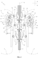
Figure 2 is a larger-scale side view, with parts removed for clarity, of the forming unit according to the present invention and illustrating several successive operative conditions; -
Figure 3 is a side view, with parts removed for clarity, of the forming unit ofFigure 2 during a determined operative condition; -
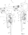
Figure 4 is a front perspective view, with parts removed for clarity, of the forming unit according to the invention; -
Figure 5 is a larger-scale rear perspective view, with parts removed for clarity, of a forming unit according to a further preferred embodiment of the present invention; -
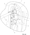
Figure 6a and6b are a larger-scale, rear perspective views of part of the forming unit ofFigure 5 during two distinct operative conditions. - With reference to
Figure 1 ,number 1 indicates as a whole a non-limiting example of a packaging apparatus for producing a plurality ofpackages 2a containing a pourable product, preferably a pourable food product such as pasteurized or UHT milk, water, fruit juice, wine, peas, beans, etc. - In detail,
packaging apparatus 1 is configured to form, seal and foldpackages 2a starting from atube 3 of packaging material. - Preferably, the packaging material has a multilayer structure (not shown), and comprises a layer of fibrous material, e.g. paper, covered on both sides with respective layers of heat-seal plastic material, e.g. polyethylene.
- In the case of
aseptic packages 2a for long-storage products, such as UHT milk, the packaging material also comprises a layer of gas-and-light barrier material, e.g. aluminum foil or ethylene vinyl alcohol (EVOH) film, which is superimposed on a layer of heat-seal plastic material, and is in turn covered with another layer of heat-seal plastic material, the latter forming the inner face ofpackage 2a eventually contacting the pourable product. - Preferably, the packaging material is initially provided in form of a
web 4. - As schematically shown in
Figure 1 , thepackaging apparatus 1 comprises: -
tube folding devices 5 for progressively folding theweb 4 intotube 3, in a manner known and not described in detail, and for providingtube 3 with a longitudinal seal by means of a sealingelement 40; - a filling device for filling
tube 3 with the pourable product; - a forming
unit 6 for formingtube 3 by imparting a predetermined external shape, corresponding to a precursor of the shape ofpackage 2a, to successive longitudinal portions oftube 3, and for sealingtube 3 at equally spaced cross-sections. - As visible in particular in
Figure 2 , formingunit 6 has a central axis X along whichtube 3 is fed, in use. - Central axis X is parallel to a first direction A, which preferably is a straight vertical direction.
- Hence, in use,
tube 3 is fed along first direction A, downwards, and while being filled from above is formed and sealed by formingunit 6. - In this way, a plurality of pillow packs 2 are obtained.
-
Packaging apparatus 1 further comprises a folding unit (known per se and not shown) for folding the pillow packs 2, thereby obtainingpackages 2a, according to a manner known and not described in detail. - Hence,
packaging apparatus 1 is configured to form and seal a plurality of pillow packs 2 containing the pourable product starting fromweb 4 andtube 3 and then to fold the pillow packs 2 for obtaining the aforementioned formed, sealed and foldedpackages 2a containing the pourable product. - Forming
unit 6 comprises at least one pair of formingmembers 8, known for example fromWO-A-2022017745 , which are arranged on opposite lateral sides of axis X (and therefore, in use, of tube 3) and which are configured to cyclically engage successive longitudinal portions oftube 3 for the forming thereof. - According to the non-limiting embodiment shown, each forming
member 8 includes an internally shaped half-shell configured to cyclically interact in contact withtube 3 for imprinting its shape thereon. - In detail, and according to a manner described below, forming
members 8 are movable towards and away from one another and fromtube 3 along a second direction B transversal to first direction A, and in particular orthogonal to first direction A, for cyclically surrounding and engagingtube 3 and formingtube 3 at the successive portions. - Expediently, forming
unit 6 also includes at least one pair of sealing members 10 (e.g. a sealing element and a countersealing element) arranged at opposite lateral sides of axis X and which are configured to cyclically engagetube 3 at the equally spaced cross-sections in a clamping manner, so as to define transversal sealing bands ontube 3. - More specifically, each portion of
tube 3 is longitudinally delimited by a pair of successive sealing bands. - In one embodiment, forming
unit 6 comprises a plurality of forming and sealing jaw units (known fromWO-A-2022017745 ), each forming and sealing jaw unit comprising a pair of formingmembers 8 and a pair of sealingmembers 10; and - a conveyor device (not shown, preferably a chain conveyor) for advancing the forming and sealing jaw units.
- In greater detail, each forming and sealing jaw unit includes two jaw members associated with one another, each jaw member including one forming
member 8 and one sealingmember 10. - The conveyor device is configured to advance each jaw member along a respective closed-loop path, which includes one operative section, along which the respective forming
member 8 and sealingmember 10 interact withtube 3, and one return section, according to the same configuration known fromWO-A-2022017745 . - For each jaw member, sealing
member 10 is arranged operatively downstream of formingmember 8, with respect to the advancement direction of the jaw member along the respective closed-loop path. - In light of the above, forming
members 8 and sealingmembers 10 are cyclically carried by the conveyor device along the respective operative sections and along first direction A to cyclically and repeatedly engage the successive portions oftube 3, and then along the respective return sections. -
Tube 3 is drawn (downwards) along first direction A in a known manner, due to the advancement of formingmembers 8 and sealingmembers 10 along first direction A carried by the respective forming and sealing jaw unit, and due to the interaction of formingmembers 8 and of sealingmembers 10 withtube 3. - Expediently, each forming and sealing jaw unit also comprises a cutting member (not shown), carried by one of the sealing
members 10, for repeatedly interacting withtube 3 to cuttube 3 along the previously created sealing band, once the respective tube portion is formed. - In this way, the obtained pillow packs 2 are separated from one another at the respective transversal sealing bands.
- In order to interact with
tube 3, formingmembers 8 and sealingmembers 10 are movable along second direction B, i.e. towards and away fromtube 3, towards and away from axis X and towards and away from one another, while being advanced along the respective operative sections by the conveyor device. - Forming
unit 6 comprises acam system 11 for controlling the movement of formingmembers 8 along second direction B. - In detail,
cam system 11 is configured to cyclically drive a movement of formingmembers 8 along second direction B towards and away from axis X, towards and away from one another and, in use, towards and away fromtube 3. - As visible in
Figures 2 ,3 ,4 and5 ,cam system 11 comprises: - a pair of
cam assemblies 12 arranged at opposite lateral sides of axis X (and in use of tube 3) and including, each, a fixedcam profile 13 and amovable cam profile 14; and - a plurality of
rollers 15, at least oneroller 15 being carried by each formingmember 8, configured to cyclically cooperate in contact with the movable cam profiles 14 for determining the movement of the respective formingmembers 8 along second direction B. - In other words, each forming
member 8 integrally carries at least one roller 15 (or cam follower) which is configured to cooperate in rolling contact with therespective cam assembly 12, i.e. with the respective fixedcam profile 13 andmovable cam profile 14, so as to determine the movement of such formingmember 8 along second direction B, while such formingmember 8 is conveyed along first direction A by the conveyor device. - It is specified that the movement of forming
members 8 along second direction B driven by the interaction ofrollers 15 with movable cam profiles 14 may be a composite movement including a translational component and an angular or rotational component. - On each
cam assembly 12, therollers 15 are configured to be advanced, by means of the respective forming and sealing jaw units and thus by means of the conveyor device, along a respective path S, which follows the contour of fixedcam profile 13 andmovable cam profile 14 ofsuch cam assembly 12, and which at least partially corresponds to or follows the respective aforementioned closed-loop path, as visible inFigure 2 . - In particular,
Figure 2 only shows part of the two paths S. In fact, paths S are preferably endless and extend along a closed-loop trajectory, following the respective closed-loop paths of the jaw members. - Each path S comprises an operative portion S1, extending along the respective
movable cam profile 14. In use, whenrollers 15 travel along operative portions S1, the respective formingmembers 8 are moved towards and away fromtube 3 for engagingtube 3, as shown schematically inFigure 2 . - Again, the movement of forming
members 8 towards and away from tube 3 (along second direction B) may be a composite movement including a translational component and an angular or rotational component. - Accordingly, movable cam profiles 14 are opportunely shaped for allowing the movement of forming
members 8 towards and away fromtube 3, i.e. the engagement and disengagement oftube 3 at the appropriate positions, according to a manner known and not described in detail. - As schematically shown in
Figures 3 ,6a and6b , for eachcam assembly 12movable cam profile 14 is movably coupled to fixedcam profile 13 and is movable towards and away from axis X (and in use from tube 3) between a retracted position (represented in continuous lines inFigure 3 and shown inFigure 6b ) and an extracted position (represented in dashed lines inFigure 3 and shown inFigure 6a ) with respect to the axis X. - In particular,
movable cam profile 14 is also movable, and may be arranged, in a virtually infinite number of intermediate positions between the retracted position and the extracted position. - To this end, forming
unit 6 comprises an adjustingassembly 16 for adjusting the position of movable cam profiles 14 between the retracted position and the extracted position (and in any one of the aforementioned intermediate positions). - In detail, adjusting
assembly 16 is configured to drive the movement of movable cam profiles 14 between the retracted position and the extracted position (and in any one of the aforementioned intermediate positions). - As visible in
Figures 4 and5 , adjustingassembly 16 comprises: - at least one, preferably one,
actuator 17, such as an electric motor or a pneumatic or fluid-dynamic actuator; - a
transmission system 18 forkinematically coupling actuator 17 with eachmovable cam profile 14. - The
transmission system 18 may comprise amain shaft 18a, coupled toactuator 17 for receiving torque and motion therefrom, and twocontrol bars 18b each coupled to onemovable cam profile 14. According to a modality better described in the following,actuator 17 is configured to drive a rotation of control bars 18b for moving movable cam profiles 14 between the retracted position and the extracted position. - In detail, each
movable cam profile 14 is movable between a first limit position approached to axis X (and in use to tube 3) and corresponding to the extracted position, and a second limit position withdrawn from axis X (and in use from tube 3) and corresponding to the retracted position. - The first limit position corresponds to a position in which forming
members 8 are the closest to axis X (and tube 3). The second limit position corresponds to a position in which formingmembers 8 are the farthest from axis X (and tube 3). - The intermediate positions are comprised between such first limit position and such second limit position.
- In particular, and as described in
WO-A-2022017745 , movable cam profiles 14 are selectively controllable in: - their first limit positions for defining an operative configuration of forming
unit 6, in which formingmembers 8 are controlled in respective active states, whereby formingmembers 8 cyclically engage and interact withtube 3 for the forming thereof; - their second limit positions for defining a partial operative configuration of forming
unit 6, in which formingmembers 8 are controlled in respective inactive states, whereby formingmembers 8 remain spaced and disengaged fromtube 3 while advanced along first direction A; and - their respective intermediate positions for defining further operative configurations of forming
unit 6, which are comprised between the first limit positions and the second limit positions, in which formingmembers 8 are controlled in their respective active states and cyclically engage and interact withtube 3 but from different respective distances along second direction B, each distance being associated with a respective intermediate position. - More specifically, forming
unit 6 is configured so that when movable cam profiles 14 are controlled in their second limit positions, formingmembers 8 do not reachtube 3 during their movement along second direction B driven bycam assemblies 12, and while advancing along first direction A driven by the conveyor device. - That is, when movable cam profiles 14 are controlled in their second limit positions, i.e. when forming
unit 6 is in its partial operative configuration, the travel ofrollers 15 along the respective operative portions S1 determines a movement of formingmembers 8 along second direction B towardstube 3. However, in this configuration, formingmembers 8 do not reach andcontact tube 3, thereby remaining spaced fromtube 3. - In other words, in the partial operative configuration, any significant contact between forming
members 8 andtube 3 is avoided, even though the respective forming and sealing jaw unit is advanced by the conveyor device. In this way, it is possible to reduce the risk ofdamaging tube 3 and/or packs 2 when operating at elevated production speeds and/or with the filling level of tube 3 (i.e. the measure of the volume of the pourable product present within tube 3) below or above a determined filling level. - Conveniently, forming
unit 6 may comprise a control unit configured to automatically control the movement of movable cam profiles 14 depending on the operative conditions ofpackaging apparatus 1. - In light of the above, in order to switch forming
unit 6 between one of the operative configuration and the partial operative configuration, movable cam profiles 14 are controlled between their first limit positions (i.e. their extracted positions) and their second limit positions (i.e. their retracted positions. Similarly, movable cam profiles 14 may be arranged in any of the intermediate positions, i.e. in any of the position interposed between the first limit position and the second limit position, so as to control the interaction of formingmembers 8 withtube 3. - According to an aspect of the present invention, each
cam assembly 12 comprises a guidingdevice 19 configured to constrainmovable cam profile 14 to move parallel to second direction B between the retracted position and the extracted position (i.e. in its movement towards and away from axis X or, in use, tube 3). - It is stated that the wording "constrain" indicates herein for the purpose of the invention that a movement of
movable cam profile 14 in any direction other than the second direction B is substantially prevented by guidingdevice 19. - In detail, each guiding
device 19 is configured to guide the respectivemovable cam profile 14 so that the movement of suchmovable cam profile 14 between the extracted position and the retracted position is a pure translation along second direction B. - In other words, each guiding
device 19 is configured to produce a pure translational movement of the respectivemovable cam profile 14 exclusively along second direction B. - As visible in
Figures 2 ,3 ,4 and5 ,cam assemblies 12 are arranged facing one another, and in particular movable cam profiles 14 are arranged facing one another. - Hence, with the purpose of moving between the aforesaid operative configurations and the partial operative configuration, movable cam profiles 14 are simultaneously movable towards and away from one another between their retracted positions and extracted positions (and their respective intermediate positions).
- During this movement, guiding
devices 19 are configured to force the simultaneous movement of movable cam profiles 14 towards and away from one another to occur exclusively along second direction B. - In this regard, for each
cam assembly 12, guidingdevice 19 comprises aguide element 20 integral to one of the fixedcam profile 13 and themovable cam profile 14, in the example shown integral to the fixedcam profile 13, and aslide element 21 integral to the other one of the fixedcam profile 13 and themovable cam profile 14, in the example shown integral to themovable cam profile 14.Slide element 21 is slidably coupled to guideelement 20 and is configured to slide alongguide element 20 during the movement ofmovable cam profile 14 between its retracted position and its extracted position. - Advantageously,
guide element 20 extends parallel to second direction B, thereby determining a translational movement ofslide element 21 exclusively along second direction B and constrainingslide element 21 to move exclusively along second direction B. - In light of the above, guiding
devices 19 are part of adjustingassembly 16, since they contribute to the movement of movable cam profiles 14. - Thanks to the presence of guiding
device 19, the Applicant has observed that, for eachcam assembly 12, the cyclical transition of therollers 15 between fixedcam profile 13 andmovable cam profile 14 is improved. - In this regard, a transition area T is defined between fixed
cam profile 13 and movable cam profile 14 (Figures 4 ,5 and6a ,6b ). - In detail, each
roller 15, carried in motion by the conveyor device, is configured to cyclically interact, due to the cyclical advancement of the respective jaw members, partly with fixedcam profile 13 and partly withmovable cam profile 14. - In greater detail, each
cam assembly 12 comprises a transition area T forrollers 15 defined partly by fixedcam profile 13 and partly bymovable cam profile 14 and onto which transition area T eachroller 15 is configured to cyclically pass for transiting from fixedcam profile 13 tomovable cam profile 14. - Thanks to the configuration of forming
unit 6 according to the invention, and in particular due to the presence of guidingdevices 19, the Applicant has observed that the transition of eachroller 15 from fixedcam profile 13 tomovable cam profile 14, especially when movable cam profiles 14 are in the extracted position (second limit position), is particularly smooth. Hence, wear in the aforesaid transition area T is limited, thereby leading to an increased lifespan of the involved components. - As visible in the Figures,
transmission system 18 comprises, for eachcam assembly 12, a main eccentric 22 coupled toactuator 17 and anelongated slot 23 obtained inmovable cam profile 14. - Advantageously, main eccentric 22 engages elongated
slot 23 in a sliding manner and is configured to slide within and alongelongated slot 23 for transmitting the motion fromactuator 17 to the respectivemovable cam profile 14. - In particular, each
elongated slot 23 extends along first direction A, so that main eccentric 22 is freely movable withinelongated slot 23 along first direction A. - More in particular, main eccentric 22 has a size smaller than the total extension of
slot 23 along first direction A. That is, main eccentric 22 is completely contained inslot 23. - Even more in particular, main eccentric 22 does not completely fill
slot 23, but instead is free to slidingly move therein, along first direction A. - This configuration allows for maintaining substantially the same structural configuration of forming
unit 6 and adjustingassembly 16 as the one described inWO-A-2022017745 , only adapting it for the pure translational movement of movable cam profiles 14 along second direction B according to the present invention. - In this way, the forming
unit 6 according to the present invention can be easily implemented and obtained with little effort and minimum architectural and design modifications. - Expediently,
transmission system 18 further comprises, for eachcam assembly 12, a furtherelongated slot 24 obtained inmovable cam profile 14, an auxiliary eccentric 25 engaging further elongatedslot 24 and configured to slide along furtherelongated slot 24, and alever mechanism 26 integrally coupling main eccentric 22 with auxiliary eccentric 25 and configured to transmit the motion from main eccentric 22 toauxiliary eccentric 25. -
Elongated slot 24 substantially corresponds, in shape and function, toelongated slot 23, and auxiliary eccentric 25 substantially corresponds, in shape and function, to main eccentric 22. - Conveniently, main eccentric 22 and auxiliary eccentric 25 are configured to simultaneously push the respective
movable cam profile 14 during their sliding withinelongated slot 23 and further elongatedslot 24, respectively, thereby drivingmovable cam profile 14 between its retracted position and its extracted position. - Thanks to this configuration, a stable, repeatable and reliable movement of each
movable cam profile 14 along second direction B can be easily obtained. - Preferably, but not necessarily,
lever mechanism 26 is a sort of four-bar linkage, wherein the two hinge constraints are defined by main eccentric 22 and auxiliary eccentric 25, and wherein such hinge constraints are free to move along first direction A within the respectiveelongated slots - According to one preferred advantageous embodiment depicted in
Figure 5 , and as visible in particular inFigures 6a and6b , for eachcam assembly 12 the aforementioned transition area T between fixedcam profile 13 andmovable cam profile 14 is arranged parallel to second direction B. - In this way, despite the movement of
movable cam profile 14 between the retracted position and the extracted position (and in any one of the respective intermediate positions), the terminal section of fixedcam profile 13 and the initial section ofmovable cam profile 14, which together define transition area T, remain parallel to one another (and to second direction B), and preferably coplanar with one another. - This results in an even more improved transition of
rollers 15 between fixed cam profiles 13 and movable cam profiles 14, whatever being the positioning of movable cam profiles 14. - In one embodiment, since first direction A is preferably vertical and second direction B is preferably orthogonal to first direction A, transition area T is horizontal, with respect to the direction of gravity.
- The Applicant observed that this is the optimal configuration in terms of forces and loads.
- From the foregoing, it is clear how forming
unit 6 according to the present invention allows to implement a method for forming a plurality ofpacks 2 containing a pourable product from atube 3 of packaging material, the method comprising the steps of: - a) feeding the
tube 3 along a first direction A; - b) cyclically conveying at least one pair of forming
members 8 arranged at opposite lateral sides of thetube 3 along the first direction A; - c) cyclically engaging successive portions of the
tube 3 by means of the formingmembers 8 for the forming thereof; - d) cyclically driving a movement of the forming
members 8 towards and away from thetube 3 and along a second direction B transversal, preferably orthogonal, to the first direction A;- wherein the step c) of engaging is carried out by means of the step d) of driving;
- wherein the step c) of driving is carried out by means of a
cam system 11 including a pair ofcam assemblies 12 arranged at opposite lateral sides of the tube, each cam assembly including a fixedcam profile 13 and amovable cam profile 14; - wherein the method further comprises the steps of:
- e) moving each
movable cam profile 14 with respect to the relative fixedcam profile 13 between an extracted position and a retracted position, with respect to the tube; - f) constraining the
movable cam profile 14 to move parallel to the second direction B between the extracted position and the retracted position. - The advantages of forming
unit 6 and of the related method according to the present invention will be clear from the foregoing description. - In particular, thanks to the presence of guiding
device 19, the Applicant has observed that, for eachcam assembly 12, the cyclical transition of therollers 15 between fixedcam profile 13 andmovable cam profile 14 is improved. In fact, the transition of eachroller 15 from fixedcam profile 13 tomovable cam profile 14, especially when movable cam profiles 14 are in the extracted position (second limit position) and in any one of the respective intermediate positions), is particularly smooth. Hence, wear in the aforesaid transition area T is limited, thereby leading to an increased lifespan of the involved components. - This peculiar technical effect is further enhanced if transition area T is parallel to second direction B.
- In addition, the presence of
elongated slot 23 and of main eccentric 22 slidable therein allows for maintaining substantially the same structural configuration of formingunit 6 and adjustingassembly 16 as the one described inWO-A-2022017745 , only adapting it for the pure translational movement of movable cam profiles 14 according to the present invention. - In this way, the forming
unit 6 according to the present invention can be easily implemented and obtained with little effort and minimum architectural and design modifications. - Clearly, changes may be made to forming
unit 6 as described herein without, however, departing from the scope of protection as defined in the accompanying claims.
Claims (15)
- Forming unit (6) for forming sealed packs (2) containing a pourable product from a tube (3) of packaging material, the forming unit comprising:- a central axis (X) along which the tube (3) is fed, in use;- at least one pair of forming members (8) arranged at opposite lateral sides of the central axis (X) and configured to cyclically engage successive longitudinal portions of the tube (3) for forming the tube (3);- a conveyor device for cyclically advancing the forming members (8) along a first direction (A) parallel to the central axis (X);- a cam system (11) for cyclically driving a movement of the forming members (8) towards and away from the central axis (X) and from one another and along a second direction (B) transversal to the first direction (A);the cam system (11) comprising:- a pair of cam assemblies (12) arranged at opposite lateral sides of the central axis (X) and each including a fixed cam profile (13) and a movable cam profile (14); and- a plurality of rollers (15), at least one roller (15) being carried by each forming member (8), configured to cyclically cooperate in contact with the movable cam profiles (14) for determining the movement of the respective forming members (8) along the second direction (B);wherein, for each cam assembly (12), the movable cam profile (14) is movably coupled to the fixed cam profile (13) and is movable towards and away from the central axis (X) between a retracted position and an extracted position with respect to the central axis (X);and wherein each cam assembly (12) comprises a guiding device (19) configured to constrain the movable cam profile (14) to move parallel to the second direction (B) between the retracted position and the extracted position.
- Forming unit as claimed in claim 1, wherein the guiding device (19) is configured to guide the movable cam profile (14) so that the movement of the movable cam profile (14) between the extracted position and the retracted position is a pure translation along the second direction (B) .
- Forming unit as claimed in 1 or 2, wherein the cam assemblies (12) are arranged facing one another on opposite sides of the central axis (X),the movable cam profiles (14) being simultaneously movable towards and away from one another between their retracted positions and extracted positions,and wherein the guiding devices (19) are configured to force the simultaneous movement of the movable cam profiles (14) towards and away from one another to occur exclusively along the second direction (B).
- Forming unit as claimed in any one of the foregoing claims, wherein each guiding device (19) comprises a guide element (20) integral to one of the fixed cam profile (13) and the movable cam profile (14) and a slide element (21) integral to the other one of the fixed cam profile (13) and the movable cam profile (14),
and wherein the guide element (20) extends parallel to the second direction (B) thereby determining a translational movement of the slide element (21) exclusively along the second direction (B). - Forming unit as claimed in any one of the foregoing claims, and further comprising an adjusting assembly (16) for driving the movement of the movable cam profiles (14) between the retracted position and the extracted position, the adjusting assembly (16) including:- the guiding devices (19);- at least one actuator (17);- a transmission system (18) for kinematically coupling the actuator (17) with each movable cam profile (14).
- Forming unit as claimed in claim 5, wherein the transmission system (18) comprises, for each cam assembly (12), a main eccentric (22) coupled to the actuator (17) and an elongated slot (23) obtained in the movable cam profile (14),
wherein the main eccentric (22) engages the elongated slot (23) in a sliding manner and is configured to slide along the elongated slot (23) for transmitting the motion from the actuator (17) to the movable cam profile (14). - Forming unit as claimed in claim 6, wherein the elongated slot (23) extends along the first direction (A), and wherein the main eccentric (22) is freely movable within the elongated slot (23) along the first direction (A).
- Forming unit as claimed in claim 6 or 7, wherein the transmission system (18) further comprises, for each cam assembly (12), a further elongated slot (24) obtained in the movable cam profile (14), an auxiliary eccentric (25) engaging the further elongated slot and configured to slide along the further elongated slot (24), and a lever mechanism (26) integrally coupling the main eccentric (22) with the auxiliary eccentric (25) and configured to transmit the motion from the main eccentric (22) to the auxiliary eccentric (25);
wherein the main eccentric (22) and the auxiliary eccentric (25) are configured to simultaneously push the movable cam profile (14) during their sliding within the elongated slot (22) and the further elongated slot (25), respectively, thereby driving the movable cam profile (14) between its retracted position and its extracted position. - Forming unit as claimed in any one of the foregoing claims, wherein each movable cam profile (14) is movable between a first limit position approached to the central axis (X) and corresponding to the extracted position, and a second limit position withdrawn from the central axis (X) and corresponding to the retracted position;
and wherein the movable cam profiles (14) are selectively controllable in:- their first limit positions for defining an operative configuration of the forming unit (6), in which the forming members (8) are controlled in respective active states, whereby the forming members (8) cyclically engage and interact with the tube (3) for the forming thereof; and- their second limit positions for defining a partial operative configuration of the forming unit (6), in which the forming members (8) are controlled in respective inactive states, whereby the forming members (8) remain spaced from the tube (3) while advanced along the first direction (A). - Forming unit as claimed in any one of the foregoing claims, wherein the second direction (B) is orthogonal to the first direction (A).
- Forming unit as claimed in any one of the foregoing claims, wherein each cam assembly (12) comprises a transition area (T) for the rollers (15) defined partly by the fixed cam profile (13) and partly by the movable cam profile (14) and onto which transition area (T) each roller (15) is configured to cyclically pass for transiting from the fixed cam profile (13) to the movable cam profile (14);
and wherein the transition area (T) is arranged parallel to the second direction (B). - Forming unit as claimed in claim 11, wherein the transition area (T) is horizontal with respect to the direction of gravity.
- Packaging apparatus (1) for producing sealed packages (2a) containing a pourable product from a tube (3) of packaging material, the packaging apparatus comprising:- a forming unit (6) as claimed in any one of the foregoing claims for forming successive portions of the tube (3) while the tube is fed along the first direction (A);- at least one pair of sealing members (10) arranged at opposite sides of the central axis (X) and configured to cyclically engage the tube (3) at successive cross-sections thereof for sealing the tube along transversal sealing bands.
- Method for forming a plurality of packs (2) containing a pourable product from a tube (3) of packaging material, the method comprising the steps of:a) feeding the tube (3) along a first direction (A);b) cyclically conveying at least one pair of forming members (8) arranged at opposite lateral sides of the tube (3) along the first direction (A);c) cyclically engaging successive portions of the tube (3) by means of the forming members (8) for the forming thereof;d) cyclically driving a movement of the forming members (8) towards and away from the tube (3) and along a second direction (B) transversal to the first direction (A);wherein the step c) of engaging is carried out by means of the step d) of driving;wherein the step c) of driving is carried out by means of a cam system (11) including a pair of cam assemblies (12) arranged at opposite lateral sides of the tube (3), each cam assembly (12) including a fixed cam profile (13) and a movable cam profile (14);wherein the method further comprises the steps of:e) moving each movable cam profile (14) with respect to the relative fixed cam profile (13) between an extracted position and a retracted position, with respect to the tube;f) constraining the movable cam profile (14) to move parallel to the second direction (B) between the extracted position and the retracted position.
- Method as claimed in claim 14, wherein the step f) of constraining comprises guiding the movable cam profile (14) during its movement between the extracted position and the retracted position so that such movement is a pure translation along the second direction (B).
Applications Claiming Priority (1)
| Application Number | Priority Date | Filing Date | Title |
|---|---|---|---|
| IT102023000017055A IT202300017055A1 (en) | 2023-08-09 | 2023-08-09 | UNIT FOR FORMING PACKETS CONTAINING A POURABLE PRODUCT AND METHOD FOR FORMING PACKETS CONTAINING A POURABLE PRODUCT |
Publications (1)
| Publication Number | Publication Date |
|---|---|
| EP4506270A1 true EP4506270A1 (en) | 2025-02-12 |
Family
ID=88291315
Family Applications (1)
| Application Number | Title | Priority Date | Filing Date |
|---|---|---|---|
| EP24184214.5A Pending EP4506270A1 (en) | 2023-08-09 | 2024-06-25 | Forming unit for forming sealed packs containing a pourable product and method for forming sealed packs containing a pourable product |
Country Status (4)
| Country | Link |
|---|---|
| EP (1) | EP4506270A1 (en) |
| CN (1) | CN121712695A (en) |
| IT (1) | IT202300017055A1 (en) |
| WO (1) | WO2025031661A1 (en) |
Citations (3)
| Publication number | Priority date | Publication date | Assignee | Title |
|---|---|---|---|---|
| EP0887264A1 (en) * | 1997-06-27 | 1998-12-30 | Tetra Laval Holdings & Finance SA | Packaging unit for continuously producing sealed packages, containing pourable food products, from a tube of packaging material |
| WO2019115315A1 (en) * | 2017-12-13 | 2019-06-20 | Tetra Laval Holdings & Finance S.A. | A package forming unit for forming sealed packages |
| WO2022017745A1 (en) | 2020-07-23 | 2022-01-27 | Tetra Laval Holdings & Finance S.A. | Package forming unit, packaging apparatus having a package forming unit and method for forming packages |
-
2023
- 2023-08-09 IT IT102023000017055A patent/IT202300017055A1/en unknown
-
2024
- 2024-06-25 CN CN202480052235.7A patent/CN121712695A/en active Pending
- 2024-06-25 EP EP24184214.5A patent/EP4506270A1/en active Pending
- 2024-06-25 WO PCT/EP2024/067763 patent/WO2025031661A1/en active Pending
Patent Citations (3)
| Publication number | Priority date | Publication date | Assignee | Title |
|---|---|---|---|---|
| EP0887264A1 (en) * | 1997-06-27 | 1998-12-30 | Tetra Laval Holdings & Finance SA | Packaging unit for continuously producing sealed packages, containing pourable food products, from a tube of packaging material |
| WO2019115315A1 (en) * | 2017-12-13 | 2019-06-20 | Tetra Laval Holdings & Finance S.A. | A package forming unit for forming sealed packages |
| WO2022017745A1 (en) | 2020-07-23 | 2022-01-27 | Tetra Laval Holdings & Finance S.A. | Package forming unit, packaging apparatus having a package forming unit and method for forming packages |
Also Published As
| Publication number | Publication date |
|---|---|
| IT202300017055A1 (en) | 2025-02-09 |
| CN121712695A (en) | 2026-03-20 |
| WO2025031661A1 (en) | 2025-02-13 |
Similar Documents
| Publication | Publication Date | Title |
|---|---|---|
| EP2586716B1 (en) | Folding unit for pourable food product packaging machines | |
| EP2586719B1 (en) | Folding unit and method for producing pourable food product packages | |
| EP2284084B1 (en) | Folding unit for pourable food product packaging machines | |
| EP3053834B1 (en) | Forming assembly and method for forming a plurality of sealed packs for pourable food products starting from a tube of packaging material | |
| US9902566B2 (en) | Conveyor for an article handling unit, in particular for a folding unit for producing packages of pourable food products | |
| EP2631188B1 (en) | Folding unit for pourable food product packaging machines | |
| EP1832518B1 (en) | Packaging machine for producing sealed packages of pourable food products | |
| EP3053835B1 (en) | Forming assembly and method for forming a plurality of sealed packs for pourable food products starting from a tube of packaging material | |
| DK2955117T3 (en) | Supply unit for supplying sealed packages of pourable food products | |
| JP2023535414A (en) | PACKAGE FORMING UNIT, PACKAGING APPARATUS HAVING PACKAGE FORMING UNIT AND PACKAGE FORMING METHOD | |
| EP1325868A1 (en) | Packaging unit for continuously producing sealed packages, containing pourable food products, from a tube of packaging material | |
| WO2025031661A1 (en) | Forming unit for forming sealed packs containing a pourable product and method for forming sealed packs containing a pourable product | |
| EP4265533A1 (en) | Infeed conveyor for a folding apparatus, folding apparatus having an infeed conveyor and packaging machine having a folding apparatus | |
| EP4454864A1 (en) | Package forming apparatus for a packaging machine and packaging machine for forming packages filled with a pourable product | |
| EP3351478A1 (en) | Forming member for controlling the volume of packs of pourable food products formed from a tube of packaging material | |
| EP4506268A1 (en) | Feeding unit for feeding semi-finished packs to a folding unit |
Legal Events
| Date | Code | Title | Description |
|---|---|---|---|
| PUAI | Public reference made under article 153(3) epc to a published international application that has entered the european phase |
Free format text: ORIGINAL CODE: 0009012 |
|
| STAA | Information on the status of an ep patent application or granted ep patent |
Free format text: STATUS: THE APPLICATION HAS BEEN PUBLISHED |
|
| AK | Designated contracting states |
Kind code of ref document: A1 Designated state(s): AL AT BE BG CH CY CZ DE DK EE ES FI FR GB GR HR HU IE IS IT LI LT LU LV MC ME MK MT NL NO PL PT RO RS SE SI SK SM TR |
|
| STAA | Information on the status of an ep patent application or granted ep patent |
Free format text: STATUS: REQUEST FOR EXAMINATION WAS MADE |
|
| 17P | Request for examination filed |
Effective date: 20250812 |