EP4506169A1 - Color patch and printing system - Google Patents
Color patch and printing system Download PDFInfo
- Publication number
- EP4506169A1 EP4506169A1 EP23784818.9A EP23784818A EP4506169A1 EP 4506169 A1 EP4506169 A1 EP 4506169A1 EP 23784818 A EP23784818 A EP 23784818A EP 4506169 A1 EP4506169 A1 EP 4506169A1
- Authority
- EP
- European Patent Office
- Prior art keywords
- color
- printing
- patch
- color patch
- region
- Prior art date
- Legal status (The legal status is an assumption and is not a legal conclusion. Google has not performed a legal analysis and makes no representation as to the accuracy of the status listed.)
- Pending
Links
Images


Classifications
-
- B—PERFORMING OPERATIONS; TRANSPORTING
- B41—PRINTING; LINING MACHINES; TYPEWRITERS; STAMPS
- B41F—PRINTING MACHINES OR PRESSES
- B41F33/00—Indicating, counting, warning, control or safety devices
- B41F33/0036—Devices for scanning or checking the printed matter for quality control
- B41F33/0045—Devices for scanning or checking the printed matter for quality control for automatically regulating the ink supply
-
- H—ELECTRICITY
- H04—ELECTRIC COMMUNICATION TECHNIQUE
- H04N—PICTORIAL COMMUNICATION, e.g. TELEVISION
- H04N1/00—Scanning, transmission or reproduction of documents or the like, e.g. facsimile transmission; Details thereof
- H04N1/46—Colour picture communication systems
- H04N1/56—Processing of colour picture signals
- H04N1/60—Colour correction or control
- H04N1/603—Colour correction or control controlled by characteristics of the picture signal generator or the picture reproducer
- H04N1/6033—Colour correction or control controlled by characteristics of the picture signal generator or the picture reproducer using test pattern analysis
-
- B—PERFORMING OPERATIONS; TRANSPORTING
- B41—PRINTING; LINING MACHINES; TYPEWRITERS; STAMPS
- B41P—INDEXING SCHEME RELATING TO PRINTING, LINING MACHINES, TYPEWRITERS, AND TO STAMPS
- B41P2233/00—Arrangements for the operation of printing presses
- B41P2233/50—Marks on printed material
- B41P2233/51—Marks on printed material for colour quality control
Definitions
- the present invention relates to a color patch and a printing system.
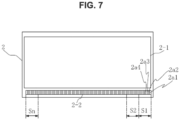
- FIG. 7 shows a printing product printed by a printing press.
- a band-like color bar 2-2 is printed on the printing product 2 in a margin portion outside a pattern area 2-1.
- the color bar 2-2 is constituted by regions S1-Sn including solid patches 2a1, 2a2, 2a3 and 2a4, which are prepared for measuring the solid region densities of the four colors.
- the regions S1-Sn correspond to the number of ink fountain keys in printing units for the respective colors in the printing press.
- the widths of the respective regions S1, S2, ..., Sn correspond to the widths of the ink fountain keys. Therefore, the total width of a color bar is determined by the number and widths of the ink fountain keys.
- Patent Document 1 JP 5022682 B
- the present invention has been achieved to solve such problems and aims to allow color management to be carried out using a color patch even if the size of the halftone dots on the printing product has changed.
- a color patch according to the present invention is a color patch for color adjustment, printed on a margin portion of a printing product printed by a printing press, the color patch comprising a non-colored portion in a region of the color patch constituted of a designated color intended to be reproduced on the printing product.
- a printing system comprises: a printing press capable of printing on a supplied sheet; a measurement device configured to measure a color of a color patch printed on a margin portion of a printing product printed by the printing press to obtain color-adjusting data; and a controller configured to adjust a supply amount of ink for each color supplied to the printing press for printing the printing product on the basis of the color-adjusting data obtained by the measurement device, wherein the color patch comprises a non-colored portion in a region of the color patch constituted of a designated color intended to be reproduced on the printing product.
- a non-colored portion is included in a region of a color patch in accordance with the present invention, and therefore color management can be carried out using the color patch even if the size of the halftone dots on the printing product has changed.
- This color patch is a color patch for color adjustment, which is included in a plate for printing a printing product and which is printed on a margin portion of the printing product printed by a printing press.
- the printing press described above is provided with a measurement device to measure a color of the color patch to obtain color-adjusting data, and the data of the color patch is used for adjusting the color to be reproduced on the printing product, on the basis of the measurement result of the measurement device.
- This color patch constitutes a color bar provided on a lithographic plate and printed by a lithographic printing press for managing the color tone of a four-color ink printing press, the color being, cyan, magenta, yellow, and black, for example.
- the color patch includes a white non-colored portion 102 in a region 101 of the color patch constituted by a designated color intended to be reproduced on the printing product.
- a plurality of non-colored portions 102 are arranged in the region 101 of the color patch.
- a plurality of color portions 103 are arranged in the region 101 of the color patch including the plurality of non-colored portions 102.
- a non-colored portion 102 is arranged between adjacent color portions 103.
- the plurality of non-colored portions 102 have a stripe pattern in a direction parallel to the conveyance direction of the printing product and are arranged in a direction perpendicular to the conveyance direction.
- the color patch may be provided for each of the four designated colors, cyan, magenta, yellow, and black.
- the color portion 103 is cyan.
- the color portion 103 is magenta.
- the color portion 103 is yellow.
- the color portion 103 is black.
- color patches may be provided for each of orange, green, and violet in addition to cyan, magenta, yellow, and black. It should be noted that there is no need to have non-colored portions for all color patches.
- the non-colored portion 102a may be lattice-shaped in the region 101a, as shown in FIG. 2 .
- Each of the plurality of color portions 103a is arranged squarely in a rectangular shape (or square).
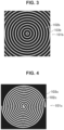
- each of the non-colored portions 102b may have a ring shape in the region 101b in the color patch.
- the non-colored portion 102c may have a spiral shape in the region 101c in the color patch as shown in FIG. 4 .
- one spiral non-colored portion 102c may be formed in a continuous integral form. Regions sandwiched by the spiral non-colored portions 102c and four corner regions exterior to the spiral non-colored portion 102c constitute colored portions 103c. In this example, there is a single integral color portion 103c in the region 101c.
- the non-colored portion 102d may have a tortuous meandering shape in the region 101d in the color patch, as shown in FIG. 5 .
- the non-colored portion 102d having a meandering shape may be formed in a continuous integral form.
- the region other than the non-colored portion 102d having a meandering shape constitutes the color portion 103d.
- the region 101d includes a single integral color portion 103d.
- This printing system includes a printing press 151 capable of printing on a supplied sheet (e.g., paper), and a measurement device 152 for measuring a color of a color patch printed on a margin portion of a printing product printed by the printing press 151 to obtain color-adjusting data.
- a printing press 151 capable of printing on a supplied sheet (e.g., paper)
- a measurement device 152 for measuring a color of a color patch printed on a margin portion of a printing product printed by the printing press 151 to obtain color-adjusting data.
- the printing system also includes a controller 153 which adjusts the ink supply amount for each color supplied to the printing press 151 for printing the printing product on the basis of the color-adjusting data obtained by the measurement device 152.
- the color patch includes a non-colored portion in the region of the color patch constituted by the designated color intended to be reproduced on the printing product.
- the color patch may include a plurality of non-colored portions arranged in the region of the color patch.
- the controller 153 includes, for example, a normal printing result of the color patch according to the embodiment described above as a reference by measuring the color with the measurement device 152.
- the controller 153 carries out the control by comparing the result obtained by the measurement device 152 in an actual printing operation with the stored reference (see patent document 1).
- the density is adjusted to a reference value (same as sample printing) by measuring the solid patch.
- the ink density is the same as that of the sample and the color should theoretically be the same in the printing product.
- the color tone may be different due to other factors. For example, when the halftone dots become larger on the printing product, the colored area increases. Moreover, when the halftone dots on the printing product appear larger, the density of the color on the pattern appears higher in human eyes.
- the operator adjusts the color tone (such as reducing the density) while checking the color of the sample pattern.
- the L*a*b* value of a striped patch on the printing product is measured by the measurement device in a trial printing.
- the area of the non-colored portion in the striped patch decreases and the area of the color portion increases relatively, and therefore the L*a*b* value in the measurement result changes.
- the color difference can be obtained by using the measurement result, and therefore the obtained value can be fed back and the color tone adjustment (reducing the density) can be performed automatically.
- the L*a*b* value is related to a commonly used colorimetric system, where "L*" represents lightness and "a*b*" represents chromaticity.
- the color difference is the difference between the colors and is the value of the distance between the points of the reference color and the measurement color on the L*a*b* color space.
- the best evaluation result was obtained when the color tone was automatically adjusted using a striped patch with a color portion area ratio of 85%.
- the plan view shape of the patch was 4.375 mm wide and 3.5 mm high. In this condition, it is considered that more accurate color management can be carried out by adjusting the color tone using a striped patch with a color portion area ratio of 85%.
- the ink contained in the ink fountain is supplied to an ink fountain roller via a plurality of ink fountain keys, and the ink supplied to the ink fountain roller is supplied to the printing plate via a group of ink rollers.
- the width of each region of the color bar illustrated in FIG. 7 is determined by the width of the ink fountain key, the width of one color bar region is 35 mm when a printing press with a 35 mm wide ink fountain key is used. Therefore, the width of the above patch has a value obtained by dividing one color bar region (35 mm) by eight patches, which are the sum of seven color patches and one patch without color.
- the height of the patch described above can be a value determined by the performance of the color tone management mechanism constituted by the measurement device 152 and the controller 153, and can be, for example, a value between 3.0 and 5.0 mm.
- color management can be carried out using the color patch even if the size of the halftone dots on the printing product changes.
Landscapes
- Engineering & Computer Science (AREA)
- Quality & Reliability (AREA)
- Multimedia (AREA)
- Signal Processing (AREA)
- Spectrometry And Color Measurement (AREA)
Abstract
Description
- The present invention relates to a color patch and a printing system.
- With respect to color tone management in multicolor printing such as offset printing, there is an adjustment method for making printing colors closer to target colors by measuring solid region densities to obtain differences from target densities. In order to obtain the solid region densities, a color bar (control strip) is provided on a part of the printing product and solid patches (color patches with a halftone dot area ratio of 100%) is printed on the color bar.
-
FIG. 7 shows a printing product printed by a printing press. A band-like color bar 2-2 is printed on the printing product 2 in a margin portion outside a pattern area 2-1. For example, in the case of four-color printing of cyan (C), magenta (M), yellow (Y), and black (K), the color bar 2-2 is constituted by regions S1-Sn including solid patches 2a1, 2a2, 2a3 and 2a4, which are prepared for measuring the solid region densities of the four colors. The regions S1-Sn correspond to the number of ink fountain keys in printing units for the respective colors in the printing press. The widths of the respective regions S1, S2, ..., Sn correspond to the widths of the ink fountain keys. Therefore, the total width of a color bar is determined by the number and widths of the ink fountain keys. - Patent Document 1:
JP 5022682 B - For example, in color printing in offset printing (lithographic printing), intermediate colors are reproduced by mixing halftone dots of the four colors of CMYK as appropriate. For this reason, in this type of color printing, when the size of the halftone dots on the printing product has changed relative to the halftone dots on the plate, the color as viewed by human eyes changes also. Such changes in the halftone dots on the printing product are not reflected in the color patch, and the color does not change in the color patch, and therefore it is not possible to check the condition of the halftone dots in color management using color patches.
- Therefore, conventionally, when there is a change in the color tone due to a change in the size of the halftone dots on the printing product as described above, a printing operator visually checks the difference in color tone from the sample printing product and adjusts the density. Such visual color adjustment is dependent on the skill of the operator, and therefore the time, number of times, and number of paper wastes required for the adjustment may increase more than necessary.
- The present invention has been achieved to solve such problems and aims to allow color management to be carried out using a color patch even if the size of the halftone dots on the printing product has changed.
- A color patch according to the present invention is a color patch for color adjustment, printed on a margin portion of a printing product printed by a printing press, the color patch comprising a non-colored portion in a region of the color patch constituted of a designated color intended to be reproduced on the printing product.
- A printing system according to the present invention comprises: a printing press capable of printing on a supplied sheet; a measurement device configured to measure a color of a color patch printed on a margin portion of a printing product printed by the printing press to obtain color-adjusting data; and a controller configured to adjust a supply amount of ink for each color supplied to the printing press for printing the printing product on the basis of the color-adjusting data obtained by the measurement device, wherein the color patch comprises a non-colored portion in a region of the color patch constituted of a designated color intended to be reproduced on the printing product.
- As described above, a non-colored portion is included in a region of a color patch in accordance with the present invention, and therefore color management can be carried out using the color patch even if the size of the halftone dots on the printing product has changed.
-
- [
FIG. 1] FIG. 1 shows a configuration diagram illustrating a configuration of a color patch according to an embodiment of the present invention. - [
FIG. 2] FIG. 2 shows a configuration diagram illustrating a configuration of another color patch according to an embodiment of the present invention. - [
FIG. 3] FIG. 3 shows a configuration diagram illustrating a configuration of another color patch according to an embodiment of the present invention. - [
FIG. 4] FIG. 4 shows a configuration diagram illustrating a configuration of another color patch according to an embodiment of the present invention. - [
FIG. 5] FIG. 5 shows a configuration diagram illustrating a configuration of another color patch according to an embodiment of the present invention. - [
FIG. 6] FIG. 6 shows a configuration diagram illustrating a configuration of a printing system according to an embodiment of the present invention. - [
FIG. 7] FIG. 7 shows a plan view schematically illustrating a printing product printed by a printing press. - A color patch according to an embodiment of the present invention will be described with reference to
FIG. 1 now. This color patch is a color patch for color adjustment, which is included in a plate for printing a printing product and which is printed on a margin portion of the printing product printed by a printing press. The printing press described above is provided with a measurement device to measure a color of the color patch to obtain color-adjusting data, and the data of the color patch is used for adjusting the color to be reproduced on the printing product, on the basis of the measurement result of the measurement device. This color patch constitutes a color bar provided on a lithographic plate and printed by a lithographic printing press for managing the color tone of a four-color ink printing press, the color being, cyan, magenta, yellow, and black, for example. - The color patch includes a white
non-colored portion 102 in aregion 101 of the color patch constituted by a designated color intended to be reproduced on the printing product. In this example, a plurality ofnon-colored portions 102 are arranged in theregion 101 of the color patch. A plurality ofcolor portions 103 are arranged in theregion 101 of the color patch including the plurality ofnon-colored portions 102. Surrounded by the plurality of arrangedcolor portions 103, anon-colored portion 102 is arranged betweenadjacent color portions 103. In this example, the plurality ofnon-colored portions 102 have a stripe pattern in a direction parallel to the conveyance direction of the printing product and are arranged in a direction perpendicular to the conveyance direction. - For example, the color patch may be provided for each of the four designated colors, cyan, magenta, yellow, and black. For example, in the cyan color patch, the
color portion 103 is cyan. For example, in the magenta color patch, thecolor portion 103 is magenta. For example, in the yellow color patch, thecolor portion 103 is yellow. For example, in the black color patch, thecolor portion 103 is black. - In addition to the four colors described above, in multi-color printing in which the designated colors of orange, green, and violet are added, color patches may be provided for each of orange, green, and violet in addition to cyan, magenta, yellow, and black. It should be noted that there is no need to have non-colored portions for all color patches.
- Moreover, in the color patch, the non-colored
portion 102a may be lattice-shaped in theregion 101a, as shown inFIG. 2 . In this example, there are a plurality of arrangednon-colored portions 102a and a plurality ofcolor portions 103a are arranged in theregion 101a of the color patch including the plurality ofnon-colored portions 102a. Each of the plurality ofcolor portions 103a is arranged squarely in a rectangular shape (or square). - As shown in
FIG. 3 , each of the non-coloredportions 102b may have a ring shape in the region 101b in the color patch. In this example, there are a plurality ofnon-colored portions 102b and the plurality ofnon-colored portions 102b are ring-shaped and are arranged concentrically. There arecolored portions 103b between adjacentnon-colored portions 102b. In this example also, there are a plurality ofcolor portions 103b in the region 101b. - The
non-colored portion 102c may have a spiral shape in theregion 101c in the color patch as shown inFIG. 4 . In this example, one spiralnon-colored portion 102c may be formed in a continuous integral form. Regions sandwiched by the spiralnon-colored portions 102c and four corner regions exterior to the spiral non-coloredportion 102c constitute coloredportions 103c. In this example, there is a singleintegral color portion 103c in theregion 101c. - Moreover, the
non-colored portion 102d may have a tortuous meandering shape in theregion 101d in the color patch, as shown inFIG. 5 . Thenon-colored portion 102d having a meandering shape may be formed in a continuous integral form. The region other than thenon-colored portion 102d having a meandering shape constitutes thecolor portion 103d. In this example, theregion 101d includes a singleintegral color portion 103d. - Next, a printing system according to an embodiment of the present invention will be described with reference to
FIG. 6 . This printing system includes aprinting press 151 capable of printing on a supplied sheet (e.g., paper), and ameasurement device 152 for measuring a color of a color patch printed on a margin portion of a printing product printed by theprinting press 151 to obtain color-adjusting data. - The printing system also includes a
controller 153 which adjusts the ink supply amount for each color supplied to theprinting press 151 for printing the printing product on the basis of the color-adjusting data obtained by themeasurement device 152. As described above, the color patch includes a non-colored portion in the region of the color patch constituted by the designated color intended to be reproduced on the printing product. For example, the color patch may include a plurality of non-colored portions arranged in the region of the color patch. Thecontroller 153 includes, for example, a normal printing result of the color patch according to the embodiment described above as a reference by measuring the color with themeasurement device 152. Thecontroller 153 carries out the control by comparing the result obtained by themeasurement device 152 in an actual printing operation with the stored reference (see patent document 1). - As described above, there are non-colored portions in the region of the color patch constituted of a designated color intended to be reproduced on the printing product, and therefore the change in the size of the halftone dots on the printing product is reflected in the color portion, allowing color management using the color patch.
- Hereinafter, the difference between a case using a solid patch and a case using a color patch in accordance with the embodiment wherein a plurality of
non-colored portions 102 having a stripe pattern are included will be examined, using the case where the halftone dots have become larger as an example. - When using a solid patch, the density is adjusted to a reference value (same as sample printing) by measuring the solid patch. The ink density is the same as that of the sample and the color should theoretically be the same in the printing product. However, when checking patterns on the printing product, the color tone may be different due to other factors. For example, when the halftone dots become larger on the printing product, the colored area increases. Moreover, when the halftone dots on the printing product appear larger, the density of the color on the pattern appears higher in human eyes.
- As described above, even if the halftone dots have become larger on the printing product, it is not possible to confirm (measure) the state of the halftone dots in the solid patch, and therefore it is unclear to what extent the density should be reduced using the measurement results. For this reason, the operator adjusts the color tone (such as reducing the density) while checking the color of the sample pattern.
- Meanwhile, in the case of using a color patch (striped patch) including a plurality of non-colored portions that are stripe-shaped, when halftone dots become larger on the printing product, this condition is also reflected on the color patch so that the dots in the color portion become larger, and therefore the area of the plurality of non-colored portions decreases. This condition is also reflected in the result of the color patch measurements.
- For example, the L*a*b* value of a striped patch on the printing product is measured by the measurement device in a trial printing. When the halftone dots become larger, the area of the non-colored portion in the striped patch decreases and the area of the color portion increases relatively, and therefore the L*a*b* value in the measurement result changes. The color difference can be obtained by using the measurement result, and therefore the obtained value can be fed back and the color tone adjustment (reducing the density) can be performed automatically. It should be noted that the L*a*b* value is related to a commonly used colorimetric system, where "L*" represents lightness and "a*b*" represents chromaticity. "a*" represents the red direction, "-a*" represents the green direction, "b*" represents the yellow direction, and "-b*" represents the blue direction. Moreover, the color difference is the difference between the colors and is the value of the distance between the points of the reference color and the measurement color on the L*a*b* color space.
- As a result of the actual trial printing, the best evaluation result was obtained when the color tone was automatically adjusted using a striped patch with a color portion area ratio of 85%. In this trial printing, the plan view shape of the patch was 4.375 mm wide and 3.5 mm high. In this condition, it is considered that more accurate color management can be carried out by adjusting the color tone using a striped patch with a color portion area ratio of 85%.
- For example, in a rotary printing press, the ink contained in the ink fountain is supplied to an ink fountain roller via a plurality of ink fountain keys, and the ink supplied to the ink fountain roller is supplied to the printing plate via a group of ink rollers. As described above, since the width of each region of the color bar illustrated in
FIG. 7 is determined by the width of the ink fountain key, the width of one color bar region is 35 mm when a printing press with a 35 mm wide ink fountain key is used. Therefore, the width of the above patch has a value obtained by dividing one color bar region (35 mm) by eight patches, which are the sum of seven color patches and one patch without color. Moreover, the height of the patch described above can be a value determined by the performance of the color tone management mechanism constituted by themeasurement device 152 and thecontroller 153, and can be, for example, a value between 3.0 and 5.0 mm. - Moreover, it has been found that the use of a color patch that includes non-colored portions having stripes parallel to the conveyance direction of the printing product makes it difficult to be affected by printing obstacles such as double sheet feeding that occur during printing and uncleanliness.
- As described above, since a non-colored portion is included in the region of the color patch in accordance with the present invention, color management can be carried out using the color patch even if the size of the halftone dots on the printing product changes.
- It should be noted that the present invention is not limited to the embodiments described above, and it is obvious that many variations and combinations can be implemented by a person skilled in the art within the technical concept of the present invention. For example, although lithographic printing is used as an example in the above, the present invention is not limited to this and can be applied similarly to other color printing.
- 101...area, 102...non-colored portion, 103...color portion, 151... printing press, 152...measurement device, 153...controller, 2... printing product, 2-1...pattern area, 2-2...color bar, 2a1-2a4...solid patch, S1-Sn...color bar region
Claims (5)
- A color patch for color adjustment, printed on a margin portion of a printing product printed by a printing press, the color patch comprising a non-colored portion in a region of the color patch constituted of a designated color intended to be reproduced on the printing product.
- The color patch according to claim 1, comprising a plurality of the non-colored portions which are arranged in the region of the color patch.
- The color patch according to claim 1 or 2, whereinthe printing press is provided with a measurement device configured to measure a color of the color patch to obtain color-adjusting data, andthe color-adjusting data of the color patch is used for adjusting the color to be reproduced on the printing product on the basis of the measurement result of the measurement device.
- A printing system, comprising:a printing press capable of printing on a supplied sheet;a measurement device configured to measure a color of a color patch printed on a margin portion of a printing product printed by the printing press to obtain color-adjusting data; anda controller configured to adjust a supply amount of ink for each color supplied to the printing press for printing the printing product on the basis of the color-adjusting data obtained by the measurement device, whereinthe color patch comprises a non-colored portion in a region of the color patch constituted of a designated color intended to be reproduced on the printing product.
- The printing system according to claim 4, wherein
the color patch comprises a plurality of non-colored portions which are arranged in the region of the color patch.
Applications Claiming Priority (2)
| Application Number | Priority Date | Filing Date | Title |
|---|---|---|---|
| JP2022063738 | 2022-04-07 | ||
| PCT/JP2023/014344 WO2023195534A1 (en) | 2022-04-07 | 2023-04-07 | Color patch and printing system |
Publications (2)
| Publication Number | Publication Date |
|---|---|
| EP4506169A1 true EP4506169A1 (en) | 2025-02-12 |
| EP4506169A4 EP4506169A4 (en) | 2026-03-25 |
Family
ID=88243020
Family Applications (1)
| Application Number | Title | Priority Date | Filing Date |
|---|---|---|---|
| EP23784818.9A Pending EP4506169A4 (en) | 2022-04-07 | 2023-04-07 | PAINT PATCH AND PRINTING SYSTEM |
Country Status (5)
| Country | Link |
|---|---|
| EP (1) | EP4506169A4 (en) |
| JP (1) | JPWO2023195534A1 (en) |
| CN (1) | CN119136987A (en) |
| CA (1) | CA3251310A1 (en) |
| WO (1) | WO2023195534A1 (en) |
Family Cites Families (11)
| Publication number | Priority date | Publication date | Assignee | Title |
|---|---|---|---|---|
| DE3830121A1 (en) * | 1988-09-05 | 1990-03-15 | Felix Brunner | METHOD AND DEVICE FOR SETTING A PRESET PRINT STANDARDS DEFINED BY A FULL OF VALUES / GRID POINT CHANGE IN AN AUTOTYPICAL PRESSURE PROCESS |
| US6178254B1 (en) * | 1998-05-29 | 2001-01-23 | Quad/Graphics, Inc. | Method for elimination of effects of imperfections on color measurements |
| ES2232381T3 (en) * | 1999-09-06 | 2005-06-01 | Komori Corporation | COLOR MANAGEMENT PROCEDURE AND DEVICE IN A PRINTING MACHINE. |
| JP2002086689A (en) * | 2000-09-13 | 2002-03-26 | Komori Corp | Printing machine color management method and apparatus |
| JP4248801B2 (en) * | 2002-04-25 | 2009-04-02 | 大日本スクリーン製造株式会社 | Dampening water supply method |
| JP4794173B2 (en) * | 2005-01-26 | 2011-10-19 | 大日本スクリーン製造株式会社 | Dampening water control method and printing apparatus |
| JP2007104277A (en) * | 2005-10-04 | 2007-04-19 | Fujifilm Corp | Image processing method and image forming apparatus |
| JP5022682B2 (en) | 2006-11-30 | 2012-09-12 | リョービ株式会社 | Print image quality control method and print image quality control apparatus for color printing machine |
| DE102007029211A1 (en) * | 2007-06-25 | 2009-01-08 | Heidelberger Druckmaschinen Ag | Improved print control strip for color measurement on substrates |
| DE102008041429B4 (en) * | 2008-08-21 | 2013-09-12 | Koenig & Bauer Aktiengesellschaft | Method for checking at least one measured value determined in a running printing process of a printing machine for its plausibility |
| JP5978679B2 (en) * | 2012-03-16 | 2016-08-24 | 株式会社リコー | Image forming apparatus |
-
2023
- 2023-04-07 CN CN202380040288.2A patent/CN119136987A/en active Pending
- 2023-04-07 EP EP23784818.9A patent/EP4506169A4/en active Pending
- 2023-04-07 JP JP2024514323A patent/JPWO2023195534A1/ja active Pending
- 2023-04-07 CA CA3251310A patent/CA3251310A1/en active Pending
- 2023-04-07 WO PCT/JP2023/014344 patent/WO2023195534A1/en not_active Ceased
Also Published As
| Publication number | Publication date |
|---|---|
| EP4506169A4 (en) | 2026-03-25 |
| WO2023195534A1 (en) | 2023-10-12 |
| CN119136987A (en) | 2024-12-13 |
| JPWO2023195534A1 (en) | 2023-10-12 |
| CA3251310A1 (en) | 2025-07-10 |
Similar Documents
| Publication | Publication Date | Title |
|---|---|---|
| Viggiano | Modeling the color of multi-colored halftones | |
| EP0272468B1 (en) | Print checking bars | |
| EP2008818B1 (en) | Improved print control strips for measuring colour on printed material | |
| US4852485A (en) | Method of operating an autotypical color offset printing machine | |
| US5224421A (en) | Method for color adjustment and control in a printing press | |
| US4310248A (en) | Color control system | |
| JP6058127B2 (en) | Control method for color printer or color copier | |
| KR20040053110A (en) | Printing method, printed matter, and printing controller | |
| US20080127849A1 (en) | Method Of Controlling Quality Of Printed Images Of Color Printing Press And Apparatus For Controlling Quality Of Printed Images | |
| US5947029A (en) | Method for assessing the quality of a multi-color print image | |
| US6109183A (en) | Measuring field block for detecting quality data in the multicolor printing of single editions | |
| US6604466B2 (en) | Color management method and apparatus for printing press | |
| EP2463102B1 (en) | Closed loop color control of selected regions using solid color regions within images | |
| EP0676285B1 (en) | Colour management in a sheet-fed rotary offset printing machine | |
| JPS61248748A (en) | Method of attaining uniform result of printing by auto-type type operation type multicolor printer and monochromatic strip set | |
| CA3251310A1 (en) | Color patch and printing system | |
| US6615727B2 (en) | Color management method and apparatus for printing press | |
| JPH06198851A (en) | Control of printing process and control strip for supervision | |
| US5730470A (en) | Quality data collection in rotary offset printing of single editions | |
| CN117203059B (en) | Method for color adjustment in a printing press | |
| US7481165B2 (en) | Method for controlling inking in an offset press | |
| JP3586573B2 (en) | Printing color tone control method | |
| GB2251580A (en) | Process for the control of printing ink application in the manufacture of multicolour print products. | |
| US8561537B2 (en) | Apparatus for the automatic determination of presetting values for inking zone setting elements of an inking unit of a press | |
| EP2058127A1 (en) | Printer print evaluation information display device and print evaluation information display method |
Legal Events
| Date | Code | Title | Description |
|---|---|---|---|
| STAA | Information on the status of an ep patent application or granted ep patent |
Free format text: STATUS: THE INTERNATIONAL PUBLICATION HAS BEEN MADE |
|
| PUAI | Public reference made under article 153(3) epc to a published international application that has entered the european phase |
Free format text: ORIGINAL CODE: 0009012 |
|
| STAA | Information on the status of an ep patent application or granted ep patent |
Free format text: STATUS: REQUEST FOR EXAMINATION WAS MADE |
|
| 17P | Request for examination filed |
Effective date: 20241104 |
|
| AK | Designated contracting states |
Kind code of ref document: A1 Designated state(s): AL AT BE BG CH CY CZ DE DK EE ES FI FR GB GR HR HU IE IS IT LI LT LU LV MC ME MK MT NL NO PL PT RO RS SE SI SK SM TR |
|
| DAV | Request for validation of the european patent (deleted) | ||
| DAX | Request for extension of the european patent (deleted) | ||
| A4 | Supplementary search report drawn up and despatched |
Effective date: 20260219 |
|
| RIC1 | Information provided on ipc code assigned before grant |
Ipc: B41F 33/00 20060101AFI20260213BHEP Ipc: H04N 1/60 20060101ALI20260213BHEP |