FIELD OF TECHNOLOGY
-
The present disclosure relates to the technical field of cleaning apparatuses, in particular to a method for controlling a cleaning apparatus, a machine-readable storage medium, and the cleaning apparatus.
BACKGROUND
-
In modern life, a variety of cleaning apparatuses have been widely used in production and life of people to achieve corresponding cleaning tasks. Typically, a cleaning apparatus may include a motor and a cleaning member (e.g., a roller brush), and the motor of the cleaning apparatus may drive the cleaning member to rotate, so that the cleaning member, when in contact with a surface of an object, such as a floor, is able to separate dirt on the surface of the object from the surface. In the case where the cleaning apparatus includes a fluid tank, the cleaning apparatus may also pump a fluid stored in the fluid tank, such as water, to the cleaning member, and achieve cleaning of the surface of the object in combination with rotation of the cleaning member.
-
Typically, the cleaning apparatus is fitted with an infrared sensing device for sensing different levels of dirt and generating different measurement values. The cleaning apparatus may compare the sensing measurement values with a preset reference value to determine the dirt level based on comparison results, and may also control the power of the cleaning apparatus, the water output of the fluid tank, and other parameters based on the determined dirt level, thereby achieving control over the cleaning apparatus.
-
However, with the use of the cleaning apparatus, various random factors such as aging of internal components of the cleaning apparatus and residual dirt may lead to misjudgment of the cleaning apparatus, which affects accurate control over the cleaning apparatus, thereby reducing the cleaning efficiency and even causing a waste of power.
SUMMARY
-
The present disclosure provides a method for controlling a cleaning apparatus, a machine-readable storage medium, and the cleaning apparatus to address at least one of the foregoing and other potential problems in the prior art.
-
According to one aspect of the present disclosure, a method for controlling a cleaning apparatus is provided. The method includes: acquiring a first dirt measurement value of the cleaning apparatus at a first moment. The method further includes: determining, based on a comparison of the first dirt measurement value with a dirt reference value of the cleaning apparatus at the first moment, a dirt reference value of the cleaning apparatus at a second moment, the second moment being a moment following the first moment. The step includes: in response to the first dirt measurement value being less than the dirt reference value of the cleaning apparatus at the first moment, maintaining the dirt reference value of the cleaning apparatus at the second moment as the dirt reference value of the cleaning apparatus at the first moment; or in response to the first dirt measurement value being greater than the dirt reference value of the cleaning apparatus at the first moment, updating the dirt reference value of the cleaning apparatus at the second moment to the first dirt measurement value.
-
In the above embodiment, by continuously updating a dirt reference value based on the comparison of a measurement value with a dirt reference value during the operation of the cleaning apparatus, the dirt reference value may be continuously calibrated in accordance with the actual situation, thereby ensuring the timeliness of detection and meanwhile reducing the influence of weakening of light transmittance of a suction pipe caused by suction of obstructions in the suction pipe, aging of the suction pipe and the like in the process of controlling the cleaning apparatus. Thus, the cleaning efficiency of the cleaning apparatus may be improved, and the power of the cleaning apparatus may be reduced, thereby greatly achieving an intelligent balance between power saving and efficiency.
-
In some embodiments, the method may further include: updating, within at least one moment from a second moment, in chronological order, a dirt reference value of the cleaning apparatus at a next moment of a corresponding moment to a dirt measurement value of the cleaning apparatus at the corresponding moment that is greater than a dirt reference value of the cleaning apparatus at the corresponding moment.
-
In the above embodiment, during the operation of the cleaning apparatus, as the obstructions, such as dirt, are further flushed or sucked away from the suction pipe, the dirt reference value may also be continuously adjusted, so that the reference value may be continuously calibrated in accordance with the actual situation, and an intelligent balance between power saving and efficiency is achieved continuously in real time.
-
In some embodiments, the method may further include: acquiring at least one initial dirt measurement value within a predetermined time interval between a moment when the cleaning apparatus is activated and a moment when a fan of the cleaning apparatus is activated; and determining, based on the at least one initial dirt measurement value, an initial dirt reference value of the cleaning apparatus.
-
In the above embodiment, by determining the dirt reference value by initial calibration within the predetermined time interval between the moment when the cleaning apparatus is activated and the moment when the fan is activated, conditions in the suction pipe may be prevented from affecting a calibration result of the cleaning apparatus after the fan of the cleaning apparatus starts to operate.
-
In some embodiments, the determining, based on the at least one initial dirt measurement value, an initial dirt reference value of the cleaning apparatus includes: determining, based on the at least one initial dirt measurement value, an initial dirt calculation value; and determining, based on the initial dirt calculation value, the initial dirt reference value of the cleaning apparatus, the initial dirt reference value being not less than a first dirt threshold value and not greater than a second dirt threshold value.
-
In some embodiments, the determining, based on the initial dirt calculation value, the initial dirt reference value includes: in response to the initial dirt calculation value being less than the first dirt threshold value, selecting the first dirt threshold value or another preset value as the initial dirt reference value.
-
In the above embodiment, by selecting the first dirt threshold value or another preset value as the dirt reference value in the case where the initial dirt calculation value is less than the first dirt threshold value, a serious deviation caused by the presence of a relatively large obstruction in the suction pipe or the aging of the suction pipe to a certain extent on setting of the dirt reference value may be reduced.
-
In some embodiments, the determining, based on the initial dirt calculation value, the initial dirt reference value includes: in response to the initial dirt calculation value being not less than the first dirt threshold value and not greater than the second dirt threshold value, setting the initial dirt calculation value to the initial dirt reference value.
-
In some embodiments, the first dirt threshold value is a preset value associated with a first light transmission capacity of a suction pipe of the cleaning apparatus, the second dirt threshold value is a preset value associated with a second light transmission capacity of the suction pipe of the cleaning apparatus, and the second light transmission capacity is greater than the first light transmission capacity.
-
In some embodiments, the method further includes: acquiring a plurality of dirt measurement values of the cleaning apparatus at a plurality of consecutive moments respectively; and in response to the plurality of dirt measurement values being less than the first dirt threshold value, emitting a prompt signal, the prompt signal instructing the cleaning apparatus to initiate a maintenance function.
-
In the above embodiment, by setting the first dirt threshold value and monitoring whether the plurality of dirt measurement values measured at a plurality of consecutive moments are all less than the first dirt threshold value, it is possible to detect in a timely manner a situation in which it is difficult to remove obstructions in the dirt pipe of the cleaning apparatus or the suction pipe is aged to a certain degree, so as to prompt a user to carry out maintenance of the cleaning apparatus in response to such a situation.
-
In some embodiments, the fan is activated at a fan start-up moment, and the first moment is any moment after the fan start-up moment.
-
In some embodiments, the fan is activated at the fan start-up moment, the first moment is a moment following the fan start-up moment, and the dirt reference value of the cleaning apparatus at the first moment is the initial dirt reference value.
-
In some embodiments, the method may further include: acquiring a second dirt measurement value of the cleaning apparatus at the second moment; and determining, based on a comparison of the second dirt measurement value with the dirt reference value of the cleaning apparatus at the second moment, a dirt level of a surface of an object to be cleaned.
-
According to a second aspect of embodiments of the present disclosure, a cleaning apparatus is provided. The cleaning apparatus includes: at least one memory, the at least one memory being coupled to the at least one processor and having stored instructions executed by the at least one processor, the instructions, when executed by the at least one processor, causing the cleaning apparatus to perform the step of implementing the method according to the first aspect of the present disclosure.
-
According to a third aspect of embodiments of the present disclosure, a machine-readable medium is provided. The machine-readable medium has stored thereon a machine-executable instruction, and the machine-executable instruction, when executed by a processor, implements the steps of the method according to the first aspect of the present disclosure.
-
The summary section is provided to introduce the selection of concepts in a simplified form, which will be further described in the detailed description below. The summary section is neither intended to identify key features or main features of the present disclosure, nor intended to limit the scope of the present disclosure.
BRIEF DESCRIPTION OF THE DRAWINGS
-
- FIG. 1 illustrates a three-dimensional schematic diagram of an exemplary cleaning apparatus in which a method according to an embodiment of the present disclosure may be implemented.
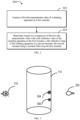
- FIG. 2 illustrates a flowchart of an exemplary method for controlling a cleaning apparatus according to some exemplary embodiments of the present disclosure.
- FIG. 3 illustrates a schematic diagram of a suction pipe provided with an infrared sensing device according to an embodiment of the present disclosure.
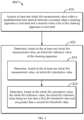
- FIG. 4 illustrates a flowchart of a method for determining an initial dirt reference value according to an embodiment of the present disclosure.
- FIG. 5 illustrates a schematic diagram of an exemplary process of dynamically adjusting a dirt reference value based on a dirt measurement value.
- FIG. 6 illustrates a schematic block diagram of a cleaning apparatus according to an embodiment of the present disclosure.
-
In the figures, the same or corresponding numerals indicate the same or corresponding parts.
DESCRIPTION OF THE EMBODIMENTS
-
The principles of the present disclosure will be described below with reference to various exemplary embodiments shown in the accompanying drawings. It should be understood that these embodiments are described merely to enable those skilled in the art to better understand and further implement the present disclosure, and are not intended to limit the scope of the present disclosure in any way. It should be noted that similar or identical reference numerals may be used in the figures where feasible, and that similar or identical reference numerals may indicate similar or identical functions. Those skilled in the art will readily recognize from the following description that alternative embodiments of the structures and methods illustrated herein may be employed without departing from the principles of the present invention as described herein.
-
As used herein, the term "include" and variations thereof indicate open-ended inclusion, i.e., "including but not limited to". Unless specifically stated, the term "or" indicates "and/or". The term "based on" indicates "at least partially based on". The terms "one exemplary embodiment" and "one embodiment" indicate "at least one exemplary embodiment". The term "another embodiment" indicates "at least one additional embodiment". The terms "first", "second", etc. may refer to different or the same object.
-
In the case where a cleaning apparatus includes a fluid tank, the cleaning apparatus may pump liquid stored in the fluid tank, such as water, to a cleaning member, and achieve cleaning of a surface, such as a floor, in combination with rotation of the cleaning member. The cleaning apparatus is further provided with a suction pipe (or, a dirt pipe). Liquid, such as sewage, generated during cleaning of the surface of an object, such as a floor, by the cleaning member may flow into a sewage storage device of the cleaning apparatus via the suction pipe for subsequent treatment.
-
As sewage and other liquid flow through the suction pipe, dirt (for example, hair, food residues, and paper) may remain on the suction pipe. The dirt may be sucked on the suction pipe, causing blockage to the suction pipe, and is therefore also referred to as "obstruction" in the present disclosure. It is to be understood that the "obstruction" in the present disclosure is not limited to dirt, and various objects sucked on the suction pipe and causing blockage to the light transmission of the suction pipe may be referred to as "obstruction".
-
Typically, the suction pipe may include a light-transmission pipe of various materials. It is to be understood that the suction pipe may be a channel through which dirt passes, and the shape of the suction pipe is not necessarily tubular, but may be any suitable shape for the cleaning apparatus. A sensor (e.g., an infrared sensing device) of the cleaning apparatus may be mounted on a side wall (e.g., an inner wall or an outer wall) of the suction pipe or in the vicinity of the suction pipe, or the like. The sensor such as the infrared sensing device may estimate a current dirt level of the surface of the object to be cleaned by sensing various obstructions such as dirt in the suction pipe. A control device (e.g., a processor) of the cleaning apparatus may control the power of the cleaning apparatus, the water output of the fluid tank, and other parameters based on the dirt level to achieve control over the cleaning apparatus.
-
Additionally, the control device of the cleaning apparatus may also control an indication device on the cleaning apparatus to present different indication information based on the dirt level so as to indicate different dirt levels to a user. For example, and only schematically, when the indication device includes a light emitting diode (LED) display device, different dirt levels may be indicated by different colors or different numbers. The user may thus control the operation of the cleaning apparatus according to the dirt level indicated by the indication device. For example, when the indication device indicates that the current dirt level of the object surface is high, the user may prolong the cleaning time of the surface without changing the power of the cleaning apparatus. In addition, the user may both increase the power of the cleaning apparatus and prolong the cleaning time of the surface, thereby achieving a higher level of cleanliness within a shorter period of time.
-
However, with the use of the cleaning apparatus, dirt may remain on the wall of the suction pipe to cause blockage, which in turn causes weakening of light transmittance of the pipe. In addition, aging of the suction pipe may also cause weakening of the light transmittance of the pipe. Moreover, there may be other random factors that cause weakening of the light transmittance of the pipe. However, whichever factor causes weakening of the light transmittance of the pipe, a measurement value sensed by the infrared sensing device will not be able to truly and accurately reflect the actual dirtiness of the current environment, thereby causing the cleaning apparatus to make a misjudgment. Moreover, a reference value used by the current cleaning apparatus is also constant. In this case, it is even more difficult to achieve accurate control over the cleaning apparatus. Therefore, the cleaning efficiency of the existing cleaning apparatus is reduced, and the power consumption of the cleaning apparatus is increased.
-
Therefore, an improved solution is urgently needed to calibrate a reference value that best meets the actual situation and ensure the timeliness of detection, and at the same time, to reduce the influence of weakening of the light transmittance of the pipe caused by suction of obstructions or aging of the pipe or other factors in the process of controlling the cleaning apparatus, thereby achieving an intelligent balance between power saving and efficiency.
-
An embodiment of the present disclosure provides an improved method for controlling a cleaning apparatus. The method includes: acquire a first dirt measurement value of the cleaning apparatus at a first moment. The method further includes: determine, based on a comparison of the first dirt measurement value with a dirt reference value of the cleaning apparatus at the first moment, a dirt reference value of the cleaning apparatus at a second moment, the second moment being a moment following the first moment. The step includes: in response to the first dirt measurement value being less than the dirt reference value of the cleaning apparatus at the first moment, maintain the dirt reference value of the cleaning apparatus at the second moment as the dirt reference value of the cleaning apparatus at the first moment; or in response to the first dirt measurement value being greater than the dirt reference value of the cleaning apparatus at the first moment, update the dirt reference value of the cleaning apparatus at the second moment to the first dirt measurement value. In this solution, a reference value closest to the actual situation may be obtained in real time through dynamic calibration, and while the timeliness of detection is ensured, the influence of weakening of the light transmittance of a pipe caused by suction of obstructions or aging of the pipe in the process of controlling the cleaning apparatus may be reduced. Thus, the efficiency of the cleaning apparatus may be improved, and the power of the cleaning apparatus may be reduced, thereby greatly achieving an intelligent balance between power saving and efficiency.
-
FIG. 1 illustrates a schematic diagram of an exemplary cleaning apparatus in which a method according to an embodiment of the present disclosure may be implemented. As shown in FIG. 1, the cleaning apparatus 100 includes a body 110. In addition, the cleaning apparatus 100 may further include a base 120 that is removably coupled to the body 110. In other words, the body 110 may be placed onto the base 120 or removed from the base 120, thereby achieving flexible disassembly of the cleaning apparatus 100 and facilitating operation by a user.
-
As shown in FIG. 1, a cleaning member cavity 112 may be provided at a bottom of the body 110 of the cleaning apparatus 100. A cleaning member (not shown) is provided in the cleaning member cavity 112. In some embodiments of the present disclosure, the cleaning member may include, but is not limited to: a roller brush, a flat mop brush, and the like. In other embodiments, the roller brush may alternatively include a tracked roller brush, a double roller brush, a single roller brush, and the like. It is to be understood that the cleaning member according to embodiments of the present disclosure is not limited thereto, but may also be a cleaning member in other form. As shown in FIG. 1, the base 120 may include an accessory storage portion 122 and a base body portion 124. The body 110 may be placed onto the base body portion 124 to achieve operations such as cleaning the cleaning member or performing charging. The body 110 may be removed from the body portion 124 to perform operations such as floor cleaning.
-
A fluid tank (not shown) may be provided in the body 110 for storing a cleaning fluid, such as clear water. It is to be understood that the cleaning fluid referred to in the embodiments of the present disclosure is not limited to clear water, but may be other solutions suitable for cleaning, which is not limited by the present disclosure. The cleaning apparatus 100 may pump liquid stored in the fluid tank, such as clear water, to the cleaning member, and achieve cleaning of various object surfaces, such as floors, in combination with rotation of the cleaning member.
-
The body 110 of the cleaning apparatus 100 may also be provided with a suction pipe 114. Liquid, such as sewage, generated during cleaning of an object surface, such as a floor, by the cleaning member may flow into a sewage storage device (not shown) of the cleaning apparatus via the suction pipe 114 for subsequent treatment.
-
In some embodiments, a sensor (not shown) such as an infrared sensing device may be provided on a side wall (e.g., an inner wall or an outer wall) of the suction pipe 114 or in the vicinity of the suction pipe for sensing a dirt level of a surface of an object to be cleaned. A control device of the cleaning apparatus 100 (for example, a processor which may be provided in the body 110, the control device will be described hereinafter by way of example as a "processor", but it is to be understood that the control device may include various types of devices having a control capability) may determine the dirt level based on a comparison of a measurement value sensed by the sensor with a reference value, and achieve control over the cleaning apparatus 100 based on the determined dirt level. For example, the processor may determine the dirt level based on the comparison of the measurement value with the reference value, and control, based on the determined dirt level, one or more parameters of the cleaning apparatus 100 such as suction power, motor speed and water output, in order to accomplish the cleaning task. In addition, the processor may also send a dirt level indication message to the user via a dirt level indication device based on the determined dirt level, and the user may achieve control over the cleaning apparatus.
-
It is to be understood that the "suction pipe" is not limited to a tubular structure, but may have any shape suitable for the cleaning apparatus, and is to be understood as a channel through which dirt passes. Furthermore, the suction pipe may have any suitable material. The present disclosure does not limit the material or shape of the suction pipe.
-
In some embodiments, the processor of the cleaning apparatus 100 may acquire the first dirt measurement value of the cleaning apparatus at the first moment, and determine, based on the comparison of the first dirt measurement value with the dirt reference value of the cleaning apparatus at the first moment, the dirt reference value of the cleaning apparatus at the second moment, the second moment being a moment following the first moment. In some embodiments, the processor may maintain, in response to the first dirt measurement value being less than the dirt reference value of the cleaning apparatus at the first moment, the dirt reference value of the cleaning apparatus at the second moment as the dirt reference value of the cleaning apparatus at the first moment; or the processor may update, in response to the first dirt measurement value being greater than the dirt reference value of the cleaning apparatus at the first moment, the dirt reference value of the cleaning apparatus at the second moment to the first dirt measurement value.
-
By calibrating the dirt reference value of the cleaning apparatus at each moment in the above way, a reference value closest to the actual situation may be obtained in real time, and while the timeliness of detection is ensured, the influence of weakening of the light transmittance of a pipe caused by suction of obstructions or aging of the pipe in the process of controlling the cleaning apparatus may be reduced. Thus, the efficiency of the cleaning apparatus may be improved, and the power of the cleaning apparatus may be reduced, thereby greatly achieving an intelligent balance between power saving and efficiency.
-
It is to be understood that the cleaning apparatus 100 illustrated in FIG. 1 is only exemplary. The method for controlling the cleaning apparatus according to an embodiment of the present disclosure may be applied in any kind of cleaning apparatus with any appearance. Moreover, the cleaning apparatus may include a cleaning apparatus in which the body and the base are separable, or may include a cleaning apparatus in which the body and the base are integrated. Furthermore, although the cleaning apparatus 100 in FIG. 1 illustrates a base, it is to be understood that the cleaning apparatus according to an embodiment of the present disclosure may also not have to include a base, which is not limited by the present disclosure.
-
The schematic diagram of an exemplary cleaning apparatus 100 in which embodiments of the present disclosure may be implemented is described above in conjunction with FIG. 1. A flowchart of a method 200 for controlling a cleaning apparatus according to an embodiment of the present disclosure is described below in conjunction with FIG. 2. The method 200 may be performed in the cleaning apparatus 100 of FIG. 1, for example, by the control device, such as the processor, in the cleaning apparatus 100. It should be understood that the method 200 may further include additional actions not shown and/or the actions shown may be omitted, and the scope of the present disclosure is not limited in this regard.
-
In block 202, the processor in the cleaning apparatus 100 may acquire a first dirt measurement value Vm1 of the cleaning apparatus 100 at a first moment. In some embodiments, a dirt measurement value Vm may be obtained based on sensing measurement of a suction pipe 114 of the cleaning apparatus 100. In some embodiments, the dirt measurement value Vm may represent a dirt level of a surface of an object to be cleaned by the cleaning apparatus 100.
-
As described above, the cleaning apparatus 100 may be provided with a sensor, such as an infrared sensing device, on an inner wall or an outer wall of the suction pipe 114 or in the vicinity of the suction pipe 114. FIG. 3 illustrates a suction pipe provided with an infrared sensing device according to an embodiment of the present disclosure. As shown in FIG. 3, the suction pipe 114 is illustrated as a cylindrical shape, but it is to be understood that the suction pipe 114 may have any shape, which is not limited by the present disclosure. The infrared sensing device may include an infrared transmitting end 310 and an infrared receiving end 320. The infrared sensing device including the infrared transmitting end 310 and the infrared receiving end 320 is disposed in the vicinity of the suction pipe 114 for sensing an obstruction, such as dirt, in the suction pipe 114. Obstructions attached to the pipe wall are schematically represented by dirt 304 and 306 in FIG. 3.
-
The infrared transmitting end 310 may emit infrared light to the suction pipe 114, and the infrared receiving end 320 may receive the infrared light from the infrared transmitting end 310 and generate a sensing measurement value, e.g., a voltage value, based on the received infrared light. It is to be understood that the larger the blocking area of the obstruction on the pipe wall or the weaker the light transmittance of the obstruction, the less infrared light is received by the infrared receiving end 320, and the smaller the sensing measurement value is generated therefrom. Therefore, the infrared sensing device may sense different dirt levels.
-
In some embodiments, the first dirt measurement value Vm1 is correlated with the size of the obstruction in the dirt pipe or the light transmittance of the obstruction. The larger the obstruction in the dirt pipe (e.g., the larger the blockage area) or the weaker the light transmittance of the obstruction, the smaller the first dirt measurement value Vm1. The smaller the obstruction in the dirt pipe (e.g., the smaller the blockage area) or the stronger the light transmission of the obstruction, the larger the first dirt measurement value Vm1.
-
In some embodiments, dirt measurement values Vm including the first dirt measurement value Vm1 may be values in the form of voltages, so as to represent different dirt levels by the voltage values. In other embodiments, the dirt measurement values Vm may also be numerical values, etc., and represent different dirt levels, etc., by the numerical values. The present disclosure does not specifically limit the representation of the dirt measurement value Vm.
-
In block 204, a processor in the cleaning apparatus 100 may determine a dirt reference value Vref2 of the cleaning apparatus 100 at a second moment T2 based on a comparison of the first dirt measurement value Vm1 with a dirt reference value Vref1 of the cleaning apparatus 100 at the first moment T1, the second moment T2 being a moment following the first moment T1. In some embodiments, the length of a time interval between the first moment T1 and the second moment T2 may be determined based on the actual operation condition of the cleaning apparatus 100, the characteristics of an object to be cleaned, etc., which is not specifically limited in the present disclosure.
-
In some embodiments, a dirt reference value Vref may be a reference value for comparing with the dirt measurement value Vm obtained by performing dirt measurement on the cleaning apparatus 100. Based on the comparison of the dirt measurement value Vm with the dirt reference value Vref, the processor may determine a dirt level of the surface of the object to be cleaned, and control one or more of the parameters of the cleaning apparatus 100, such as suction power, rotational speed and water output based on the determined dirt level, so as to efficiently accomplish the cleaning task. In addition, the processor may also send a dirt level indication message to the user via a dirt level indication device based on the determined dirt level to facilitate control over the cleaning apparatus by the user.
-
In some embodiments, the processor of the cleaning apparatus 100 may adjust a dirt reference value of the cleaning apparatus at each moment in real time based on the dirt measurement value. Accordingly, the cleaning apparatus may have a corresponding dirt reference value at the first moment T1 and a corresponding dirt reference value at the second moment T2. Depending on the dirt measurement values of the cleaning apparatus at the first moment T1 and at the second moment T2, the dirt reference value of the cleaning apparatus at the first moment T1 may be the same as or different from the dirt reference value at the second moment T2.
-
In some embodiments, as shown in block 204, the processor may determine, based on the comparison of the first dirt measurement value Vm1 with the dirt reference value Vref1 of the cleaning apparatus 100 at the first moment T1, the dirt reference value Vref2 of the cleaning apparatus 100 at the second moment T2. In some embodiments, in response to the first dirt measurement value Vm1 being less than the dirt reference value Vref1 of the cleaning apparatus 100 at the first moment T1, the processor may maintain the dirt reference value Vref2 of the cleaning apparatus 100 at the second moment T2 as the dirt reference value Vref1 of the cleaning apparatus 100 at the first moment T1. Alternatively, in response to the first dirt measurement value Vm1 being greater than the dirt reference value Vref1 of the cleaning apparatus 100 at the first moment T1, the processor may update the dirt reference value Vref2 of the cleaning apparatus 100 at the second moment T2 to the first dirt measurement value Vm1.
-
In some embodiments, the first dirt measurement value Vm1 is greater than the dirt reference value Vref1 of the cleaning apparatus 100 at the first moment T1, indicating that the size of the obstruction in the suction pipe 114 becomes smaller and the degree of cleanliness in the suction pipe is increased as compared to a moment prior to the first moment T1. For example, an airflow provided by the fan in the cleaning apparatus 100 or liquid flowing through the suction pipe 114 causes at least a portion of the obstruction in the suction pipe 114 to no longer be sucked to the wall of the pipe, but rather to be separated from the wall of the pipe with the airflow or the liquid. Thus, the first dirt measurement value Vm1 sensed by the sensor may be greater than the dirt reference value Vref1 of the cleaning apparatus 100 at the first moment T1. By updating the dirt reference value Vref2 of the cleaning apparatus 100 at the second moment T2 to the first dirt measurement value Vm1, the dirt reference value of the cleaning apparatus 100 may be calibrated, and a reference value closest to the actual situation may be obtained in real time.
-
Advantageously, by calibrating the dirt reference value of the cleaning apparatus at each moment in the above way, a reference value closest to the actual situation may be obtained in real time, and while the timeliness of detection is ensured, the influence of weakening of the light transmittance of a pipe caused by suction of obstructions or aging of the pipe in the process of controlling the cleaning apparatus may be reduced. Thus, the efficiency of the cleaning apparatus may be improved, and the power of the cleaning apparatus may be reduced, thereby greatly achieving an intelligent balance between power saving and efficiency.
-
It is to be understood that the flowchart of the method 200 in FIG. 2 may be performed for all or at least a portion of the moments during which the cleaning apparatus 100 performs a cleaning task, thereby achieving updating of the dirt reference value of the cleaning apparatus 100. In some embodiments, the cleaning apparatus 100 may update, within at least one moment from the second moment T2, in chronological order, a dirt reference value of the cleaning apparatus 100 at a next moment of a corresponding moment to a dirt measurement value of the cleaning apparatus at the corresponding moment that is greater than a dirt reference value of the cleaning apparatus 100 at the corresponding moment.
-
For example, the cleaning apparatus 100 may repeatedly perform the flowchart of the method 200 described above for one or more moments from the second moment T2, thereby achieving real-time calibration and updating of the dirt reference value of the cleaning apparatus 100. For example, the processor of the cleaning apparatus 100 may acquire a second dirt measurement value Vm2 of the cleaning apparatus 100 at the second moment T2. For example, the cleaning apparatus 100 may continue to sense obstructions such as dirt in the suction pipe 114 via a sensor such as an infrared sensing device (e.g., an infrared sensing device including an infrared transmitting end 310 and an infrared receiving end 320) and obtain the second dirt measurement value Vm2 of the cleaning apparatus at the second moment T2. The processor may maintain a dirt reference value Vref3 of the cleaning apparatus 100 at a third moment T3 as the dirt reference value Vref2 of the cleaning apparatus 100 at the second moment T2 based on the fact that the second dirt measurement value Vm2 is less than the dirt reference value Vref2 of the cleaning apparatus 100 at the second moment. Alternatively, the processor may update the dirt reference value of the cleaning apparatus 100 at the third moment T3 to the second dirt measurement value Vm2 in response to the second dirt measurement value Vm2 being greater than the dirt reference value Vref2 of the cleaning apparatus 100 at the second moment T2.
-
The processor may perform operations similar to the operations described above for one or more moments after the third moment T3. Moreover, a specific schematic process of obtaining an updated dirt reference value will be schematically described in detail below in connection with the accompanying drawings, which, for the sake of brevity, will not be repeated herein.
-
Advantageously, by means of the control method according to the embodiment of the present disclosure, sensing measurement may be continuously performed on the suction pipe 114 while an object is cleaned by the cleaning apparatus, and the dirt reference value is updated in real time based on a comparison of the dirt measurement value with the dirt reference value to control the operation of the cleaning apparatus. Thus, when, in the course of the cleaning task performed by the cleaning apparatus 100, some obstructions in the suction pipe are no longer sucked on the wall of the pipe but are peeled off from the wall of the pipe with the liquid or airflow, the cleaning apparatus 100 may achieve the calibration of the dirt reference value in time according to the real-time condition of the suction pipe and obtain the reference value closest to the actual situation. Therefore, the cleaning efficiency of the cleaning apparatus 100 may be improved, and the power of the cleaning apparatus 100 may be reduced, thereby greatly achieving an intelligent balance between power saving and efficiency.
-
In some embodiments, the processor may also obtain the second dirt measurement value of the cleaning apparatus at the second moment T2, and determine a dirt level of a surface of an object to be cleaned based on a comparison of the second dirt measurement value and the dirt reference value of the cleaning apparatus 100 at the second moment T2. The processor may further control, based on the determined dirt level, one or more parameters of the cleaning apparatus 100 such as suction power, motor speed, and water output, in order to accomplish the cleaning task. In addition, the processor may also send a dirt level indication message to the user via a dirt level indication device based on the determined dirt level, and the user may achieve control over the cleaning apparatus.
-
In some embodiments, within a time interval (e.g., a predetermined time interval, for example, 1 second) between a moment when the cleaning apparatus 100 is activated and a moment when a fan of the cleaning apparatus 100 is activated, the cleaning apparatus 100 may sense the suction pipe 114 by a sensor, such as an infrared sensing device, to obtain at least one initial dirt measurement value Vinitial. The activation of the cleaning apparatus 100 as described above may be referred to as "startup", which may be performed, for example, by pressing a start button of the cleaning apparatus 100 to turn on the power. The activation of the fan as described above may be referred to as "fan activation", which indicates that the fan in the cleaning apparatus 100 starts to provide airflow and the cleaning apparatus 100 starts to carry out a cleaning action. Therefore, within the (predetermined) time interval between the moment when the cleaning apparatus 100 is activated and the moment when the fan of the cleaning apparatus 100 is activated, the fan of the cleaning apparatus 100 has not yet been activated and there is no airflow or liquid flowing through the suction pipe 114. However, in this case, with the activation of the cleaning apparatus 100, the infrared sensing device of the cleaning apparatus 100 is switched on and the processor may acquire one or more initial dirt measurement values Vinitial for the suction pipe 114. The one or more initial dirt measurement values Vinitial may represent an initial condition of the suction pipe 114 when there is no liquid or airflow flowing through. The processor may determine an initial dirt reference value Vinitialref of the cleaning apparatus 100 based on the acquired one or more initial dirt measurement values Vinitial.
-
It is to be understood that the initial dirt measurement value may be acquired one or more times within the predetermined time interval between the moment when the cleaning apparatus 100 is activated and the moment when the fan of the cleaning apparatus 100 is activated. When the dirt measurement value is acquired multiple times, the largest dirt measurement value may be selected as the initial dirt reference value Vinitialref. In addition, when the dirt measurement value is acquired multiple times, an average of the dirt measurement values of the multiple measurements may alternatively be selected as the initial dirt reference value Vinitialref. Furthermore, as described in detail below, it is also possible to determine the initial dirt reference value Vinitialref of the cleaning apparatus 100 based on a relationship between the initial dirt measurement value and the first dirt threshold value and the second dirt threshold value.
-
Advantageously, by acquiring the initial dirt reference value in real time prior to the cleaning operation of the cleaning apparatus 100, a real-time calibration is performed each time when the user uses the cleaning apparatus 100, avoiding the possible reference interference based on the complex dirt condition of the surface to be cleaned that may occur during the cleaning process. Thus, a more accurate dirt level may be obtained.
-
In some embodiments, the fan in the cleaning apparatus 100 is activated at a fan start-up moment, the first moment T1 described in conjunction with the method 200 may be the moment following the fan start-up moment, and accordingly, the dirt reference value Vref1 of the cleaning apparatus at the first moment T1 is the initial dirt reference value Vinitialref. Furthermore, in yet other embodiments, the fan in the cleaning apparatus 100 is activated at the fan start-up moment, and the first moment T1 described in conjunction with the method 200 may be any moment after the fan start-up moment.
-
Hereinafter, a specific process of obtaining an initial dirt reference value Vinitialref according to embodiments of the present disclosure will be described in conjunction with FIG. 4.
-
FIG. 4 illustrates a flowchart of a method 400 for determining the initial dirt reference value according to an embodiment of the present disclosure. The method 400 may be performed in the cleaning apparatus 100 of FIG. 1, for example, by the control device, such as the processor, in the cleaning apparatus 100. It should be understood that the method 400 may further include additional actions not shown and/or the actions shown may be omitted, and the scope of the present disclosure is not limited in this regard.
-
In block 410, at least one initial dirt measurement value Vinitial is acquired within the predetermined time interval between the moment when the cleaning apparatus 100 is activated and the moment when the fan of the cleaning apparatus 100 is activated. In some embodiments, there is typically a predetermined time interval (e.g., 1 second) between the moment when the cleaning apparatus 100 is activated and the moment when the fan of the cleaning apparatus 100 is activated. Within the predetermined time interval, the fan of the cleaning apparatus 100 has not yet been activated (i.e., no airflow passes through the suction pipe 114) and no liquid flows through the suction pipe 114. In this case, the cleaning apparatus 100 may turn on a sensor, such as an infrared sensing device, to acquire one or more initial dirt measurement values sensed against the suction pipe 114. The one or more initial dirt measurement values may represent an initial condition of the suction pipe 114 in which neither liquid or airflow flows through.
-
In the following description, for illustrative purposes, it will be illustrated as an example that the dirt measurement value is a voltage value. It is to be understood, however, that this is only exemplary and that the dirt measurement value may also be a measurement value represented by various types, such as a numeric value, which is not limited by the present disclosure. In some embodiments, the sensor may measure the suction pipe 114 one time and acquire an initial dirt measurement value Vinitial. In addition, to make the measurement value more accurate, the sensor may measure the suction pipe 114 multiple times within the predetermined time interval and obtain a plurality of initial dirt measurement values Vinitial1, Vinitial2, ..., and Vinitialn, respectively, where n is the number of times of measurements performed by the sensor during the initial measurement, and accordingly, the processor may obtain n initial dirt measurement values Vinitial.
-
In block 420, the processor may determine an initial dirt reference value of the cleaning apparatus 100 based on the at least one initial dirt measurement value. In some embodiments, as described above, the processor may use a maximum value of the one or more initial dirt measurement values as the initial dirt reference value. Additionally, the processor may alternatively use an average value of the one or more initial dirt measurement values as the initial dirt reference value. Further, the processor may determine the initial dirt reference value based on a relationship between the one or more initial dirt measurement values and the first dirt threshold value and the second dirt threshold value. Hereinafter, a specific implementation process of the processor determining the initial dirt reference value based on the relationship between the one or more initial dirt measurement values and the first dirt threshold value and the second dirt threshold value will continue to be described in connection with FIG. 4.
-
As described in
FIG. 4, in
block 424, the processor may determine an initial dirt calculation value based on the one or more initial dirt measurement values obtained in
block 410. When measurement is performed only one time in block 402, the initial dirt measurement value
Vinitial may be determined as the initial dirt calculation value
Vint . When measurement is performed multiple times in block 404 and a plurality of initial dirt measurement values
Vinitial1, Vinitial2, ...,
and Vinitialn are obtained respectively, the processor may perform processing based on the plurality of obtained initial dirt measurement values
Vinitial1, Vinitial2, ...,
and Vinitialn to determine the initial dirt calculation value
Vint. In one embodiment, the processor may perform averaging processing on the plurality of obtained initial dirt measurement values
Vinitial1, Vinitial2, ...,
and Vinitialn and use the average value as the initial dirt calculation value
Vint, as shown in Equation 1 below.
-
In addition, other methods may be employed to process the plurality of initial dirt measurement values Vinitial1, Vinitial2, ..., and initialn to obtain the initial dirt calculation value Vint, which is not limited by the present disclosure.
-
In block 426, the processor may obtain an initial dirt reference value Vinitialref based on the initial dirt calculation value Vint to be used as an initial dirt reference value for the cleaning apparatus, where the initial dirt reference value Vinitialref is not less than the first dirt threshold value Vth1 and not greater than the second dirt threshold value Vth2, i.e., Vth1 <Vinitialref < Vth2.
-
In some embodiments, the first dirt threshold value Vth1 is a preset value associated with a first light transmission capacity of the cleaning apparatus 100, the second dirt threshold value Vth2 is a preset value associated with a second light transmission capacity of the cleaning apparatus 100, and the second light transmission capacity is greater than the first light transmission capacity. In some embodiments, the first dirt threshold value Vth1 may be a lower limit threshold value preset for the cleaning apparatus 100, e.g., corresponding to a reference value in the case that the suction pipe 114 of the cleaning apparatus 100 is aged to a certain degree (e.g., 40%), for example, a corresponding voltage value of 3.0 V. The second dirt threshold value Vth2 may correspond to an upper limit reference value in the case that there is hardly any obstruction on the suction pipe 114 of the cleaning apparatus 100, e.g., a voltage value of 5.0 V. It is to be understood that when the suction pipe 114 of the cleaning apparatus 100 is aged to a certain degree, the light transmission capacity of the suction pipe may be reduced. In contrast, in the case that there is hardly any obstruction on the suction pipe 114 of the cleaning apparatus 100, the light transmission capacity of the suction pipe 114 is strong. Accordingly, the light transmission capacity of the suction pipe corresponding to the second dirt threshold value is greater than the light transmission capacity of the suction pipe corresponding to the first dirt threshold value.
-
Assuming that the initial dirt calculation value Vint obtained in block 424 is 3.6 V, since the initial dirt calculation value Vint of 3.6 V is within the range of 3.0 V-5.0 V, the processor may set the dirt calculation value Vint of 3.6 V as the initial dirt reference value Vinitialref. In other words, the processor may, in response to the initial dirt calculation value being not less than the first dirt threshold value and not greater than the second dirt threshold value, set the initial dirt calculation value to the initial dirt reference value Vinitialref.
-
Assuming that the initial dirt calculation value Vint obtained in block 424 is 2.8 V, since the initial dirt calculation value Vint of 2.8 V is less than the first dirt threshold value Vth1, the processor does not set the dirt calculation value Vint of 2.8 V as the initial dirt reference value Vinitialref, but alternatively, sets the first dirt threshold value Vth1 as the initial dirt reference value Vinitialref. In other words, the processor may, in response to the initial dirt calculation value being less than the first dirt threshold value, set the first dirt threshold value to the initial dirt reference value Vinitialref. Further, in other embodiments, the processor may, in response to the initial dirt calculation value being less than the first dirt threshold value, set another preset value different from the first dirt threshold value to the initial dirt reference value Vinitialref. In some embodiments, the other preset value may be a value within a range of ±10% of the first dirt threshold value. In addition, a suitable value may be set for the other preset value according to the actual application, which is not limited by the present disclosure.
-
Advantageously, by setting a lower limit measurement threshold value for the cleaning apparatus and using the lower limit threshold value or a preset value within a certain range of the lower limit threshold value as the initial dirt reference value when the initial dirt measurement value is smaller than the lower limit threshold value, an abnormal value sensed during the initial measurement may be discarded, so as to avoid the situation that due to the presence of an over-sized obstruction capable of being sucked away later, the initial measurement value is too small and thus causes an excessive initial error.
-
It is to be understood that by obtaining a measurement value representing the initial condition of the suction pipe 114 in the case where no liquid or airflow flows through the suction pipe within the predetermined time interval between the moment when the cleaning apparatus 100 is activated and the moment when the fan of the cleaning apparatus 100 is activated and by determining the initial dirt reference value for use with the cleaning apparatus 100 based on the initial dirt measurement value, the impact on the process of calibrating the reference value for the cleaning apparatus 100 after the suction pipe 114 starts to operate may be greatly reduced.
-
The processor may, starting from one or more moments after the initial moment, sequentially update, in chronological order, the dirt reference value of the cleaning apparatus 100 at a moment following a corresponding moment to a dirt measurement value of the cleaning apparatus 100 at the corresponding moment that is greater than the dirt reference value of the cleaning apparatus 100 at the corresponding moment. For example, in some embodiments, as the fan of the cleaning apparatus 100 is activated, in response to a dirt measurement value acquired at a moment being greater than the initial dirt reference value, the processor may use the dirt measurement value acquired at this moment that is greater than the dirt reference value as the dirt reference value Vref, of the cleaning apparatus at a moment following this moment, thereby achieving calibration and updating of the dirt reference value.
-
After the initial dirt reference value is determined, as the fan of the cleaning apparatus is activated, the airflow is provided into the suction pipe 114, and the obstructions in the suction pipe 114 may be sucked away from the suction pipe 114 with the airflow. Therefore, the dirt measurement value obtained by the sensor sensing the suction pipe 114 may be greater than the initial dirt reference value. In this case, the processor may update the initial dirt reference value with the sensing measurement value, and use the sensing measurement value as the dirt reference value for the cleaning apparatus. The sensor may also continue to sense the suction pipe 114, compare the sensed dirt measurement value with the dirt reference value at the current moment, and, in the event that the dirt measurement value is greater than the dirt reference value at the current moment (indicating that obstructions in the suction pipe are further sucked away), update the dirt reference value at the current moment with the sensed dirt measurement value and uses the updated dirt reference value as the dirt reference value at the next moment.
-
Since the continuous operation of the cleaning apparatus 100 may cause the quantity of obstructions in the suction pipe 114 to change, the sensor may continuously sense the suction pipe 114, and the processor may accordingly perform the above-described comparison process and the process of updating the dirt reference value, thereby achieving dynamic calibration of the dirt reference value. If there is no change in the obstructions in the suction pipe 114 or the quantity of the obstructions increases, resulting in the measurement value being less than the current dirt reference value, the processor may calculate a dirt level based on the comparison of the reference value and the measurement value, and control the operation of the cleaning apparatus based on the determined dirt level and/or send an indication message regarding the dirt level to the user. If the size of the obstructions in the suction pipe 114 is reduced, the dirt measurement value may be greater than the current dirt reference value, whereby the dirt reference value may be updated with the dirt measurement value. Therefore, the dirt reference value may be calibrated while the obstructions in the suction pipe 114 undergo a subtle change, which may ensure the timeliness of detection results. Thus, the cleaning efficiency of the cleaning apparatus may be improved and the power of the cleaning apparatus may be reduced, thereby greatly achieving an intelligent balance between power saving and efficiency.
-
In yet other embodiments, in the case where the initial dirt calculation value is less than the first dirt threshold value, and the first dirt threshold value or another preset value is used as the initial dirt reference value, the sensor may perform sensing measurement on the suction pipe 114 multiple times at a plurality of consecutive moments as the fan of the cleaning apparatus is activated. If the dirt measurement values acquired at the plurality of consecutive moments are all less than the first dirt threshold value, it may indicate that the obstructions in the suction pipe 114 are too large and difficult to flush away by liquid or suck away by airflow, or it may alternatively indicate that the suction pipe 114 is aged to a certain degree. In this case, the processor may emit a prompt signal that instructs the cleaning apparatus to initiate a maintenance function. For example, the prompt signal may prompt the cleaning apparatus 100 to perform a self-cleaning function to remove large pieces of dirt and other obstructions from the suction pipe 114 for the next power-up operation. Alternatively, the prompt signal may prompt the user to perform corresponding maintenance operations on the cleaning apparatus 100 to prolong the service life of the cleaning apparatus 100.
-
For illustrative purposes, an exemplary process of dynamically adjusting the dirt reference value based on the dirt measurement value will be described below in connection with FIG. 5. FIG. 5 illustrates a schematic diagram of an exemplary process of dynamically adjusting the dirt reference value based on the dirt measurement value. FIG. 5 schematically shows eight moments t0 to t 7, but it is to be understood that this is only schematic. The cleaning apparatus 100 may perform dirt sensing at moments of any quantity and obtain corresponding dirt measurement values. Additionally, although the vertical axis in FIG. 5 is depicted in terms of voltage, this is for illustrative purposes and is exemplary, and a person skilled in the art may employ any form to represent dirt measurement values, which is not limited by the present disclosure.
-
As shown in FIG. 5, the initial moment t0 corresponds to an initial moment when initial measurement is performed on the suction pipe of the cleaning apparatus 100 within a predetermined time interval after the cleaning apparatus 100 is powered on and activated. At the initial moment, the processor may acquire an initial dirt measurement value VM0 of 4.3 V based on a sensing result of the sensor. It is to be understood that each moment in FIG. 5 corresponds to either a dirt measurement value obtained from a single measurement for the moment, or a measurement result after processing (e.g., averaging) of a plurality of dirt measurement values obtained from a plurality of measurements for the moment, and the present disclosure does not limit the process of acquiring a dirt measurement value corresponding to each moment.
-
The processor may determine the initial dirt measurement value of 4.3 V acquired at the initial moment t0 as the initial dirt reference value Vinitialref of the cleaning apparatus. The processor may determine the initial dirt reference value Vinitialref as a dirt reference value Vref1 of the cleaning apparatus at a moment t1. At the moment t1 (e.g., corresponding to a moment after the fan is activated), the sensor may sense the suction pipe 114 and obtain a first sensing measurement value VM1 of 4.5 V (e.g., some of the obstructions in the suction pipe 114 are sucked away). Since the first sensing measurement value VM1 is greater than the dirt reference value Vref1 of the cleaning apparatus 100 at the moment t1, the processor updates the dirt reference value Vref of the cleaning apparatus with the first sensing measurement value VM1, and uses the first sensing measurement value VM1 as a dirt reference value Vref2 of the cleaning apparatus at the next moment t2, so that the updated dirt reference value Vref2 is equal to the first sensing measurement value VM1, i.e., Vref2 = VM1 = 4.5 V.
-
At the moment t2, the sensor may continue to sense the suction pipe 114 and obtain a second sensing measurement value VM2 of 4.7 V. Since the second sensing measurement value VM2 is greater than the dirt reference value Vref2 of 4.5 V at the current moment t2, the processor updates the dirt reference value Vref of the cleaning apparatus with the second sensing measurement value VM2, and uses the second sensing measurement value VM2 as a dirt reference value Vref3 of the cleaning apparatus at the next moment t3 , so that the updated dirt reference value Vref is equal to the second sensing measurement value VM2, i.e., Vref3 = VM2 = 4.7 V.
-
At the moment t3 , the sensor may continue to sense the suction pipe 114 and obtain a third sensing measurement value VM3 of 4.6 V. Since the third sensing measurement value VM3 is less than the dirt reference value Vref3 of 4.7 V at the current moment, the processor does not update the dirt reference value Vref, but instead maintains a dirt reference value Vref4 at the next moment t4 as the dirt reference value Vref3 at the moment t3 . Additionally, the processor may determine a dirt level (e.g., L1) based on a difference (0.1 V) between the dirt reference value Vref3 and the third sensing measurement value VM3 at the current moment t3 , and control the operation of the cleaning apparatus based on the determined dirt level. In some embodiments, the dirt level may be proportional to a difference between the dirt reference value and the dirt measurement value. The greater the difference between the dirt reference value and the dirt measurement value, the greater the dirt level. The processor may control the operation of the cleaning apparatus by adjusting one or more parameters such as suction power, motor speed, and water output. For example, the processor may control the motor speed to be w1 if the dirt level is L1. It is to be understood that the motor speed is associated with the speed of the cleaning member, and by controlling the motor speed, the cleaning member may be driven to clean an object at different speeds.
-
At the moment t4 , the sensor may continue to sense the suction pipe 114 and obtain a fourth sensing measurement value VM4 of 4.8 V (indicating that the obstructions in the suction pipe continue to decrease currently). Since the fourth sensing measurement value VM4 is greater than the dirt reference value Vref4 of 4.7 V at the current moment t4 , the processor updates the dirt reference value Vref of the cleaning apparatus with the fourth sensing measurement value VM4, and uses the fourth sensing measurement value VM4 as a dirt reference value Vref5 of the cleaning apparatus at the next moment t5, so that the updated dirt reference value Vref is equal to the fourth sensing measurement value VM4, i.e., Vref5 = VM4 = 4.8 V.
-
At the moment t5 , the sensor may continue to sense the suction pipe 114 and obtain a fifth sensing measurement value VM5 of 4.5 V. Since the fifth sensing measurement value VM5 is less than the current dirt reference value Vref of 4.8 V, the processor does not update the dirt reference value Vref, but instead maintains a dirt reference value Vref at the next moment t6 as the dirt reference value Vref5 at the moment t5 . Additionally, the processor may determine a dirt level (e.g., L3) based on a difference (e.g., 0.3 V) between the dirt reference value Vref5 of the cleaning apparatus at the moment t5 and the fifth sensing measurement value VM5, and control operation of the cleaning apparatus based on the determined dirt level. In some embodiments, the dirt level L3 is greater than the dirt level L1. The processor may control the motor speed to be w3 if the dirt level is L3, and w3 is greater than w1.
-
At the moment t6 , the sensor may continue to sense the suction pipe 114 and obtain a sixth sensing measurement value VM6 of 4.6 V. Since the sixth sensing measurement value VM6 is smaller than the dirt reference value Vref6 of 4.8 V at the current moment, the processor does not update the dirt reference value Vref, but instead maintains a dirt reference value Vref7 at the next moment t7 as the dirt reference value Vref6 at the moment t6. Additionally, the processor may determine a dirt level (e.g., L2) based on a difference (0.2 V) between the dirt reference value Vref6 of the cleaning apparatus at the moment t6 and the sixth sensing measurement value VM6, and control operation of the cleaning apparatus based on the determined dirt level. In some embodiments, the dirt level L2 is greater than the dirt level L1 but smaller than the dirt level L3. The processor may control the motor speed to be w2 if the dirt level is L2, and w2 is greater than w1 and smaller than w3.
-
At the moment t7 , the sensor may continue to sense the suction pipe 114 and obtain a seventh sensing measurement value VM7 of 4.4 V. Since the seventh sensing measurement value VM7 is smaller than the dirt reference value Vref7 of 4.8 V at the current moment t7 , the processor does not update the dirt reference value Vref, but instead maintains a dirt reference value Vref8 at the next moment t8 as the dirt reference value Vref7 at the moment t7 . Additionally, the processor may determine a dirt level (e.g., L4) based on a difference (0.4 V) between the dirt reference value Vref7 and the seventh sensing measurement value VM7, and control the operation of the cleaning apparatus based on the determined dirt level. In some embodiments, the processor may control the motor speed to be w4 if the dirt level is L4, and w4 is greater than w3.
-
The above, in conjunction with FIG. 5, describes a schematic process of dynamically adjusting a dirt reference value and controlling the operation of the cleaning apparatus according to embodiments of the present disclosure. Although the time intervals between moments in FIG. 5 are illustrated as being equal, it is to be understood that the processor may control the sensor to perform sensing measurement at any moment instead of periodically, and the present disclosure does not limit when and how many times the processor performs the measurement.
-
FIG. 6 illustrates a block diagram of a cleaning apparatus according to an embodiment of the present disclosure. The block diagram in FIG. 6 represents the structure of the cleaning apparatus 600 in the form of blocks. It is to be understood that the block diagram in FIG. 6 may further include components having other functions.
-
As shown in FIG. 6, the cleaning apparatus 600 according to an embodiment of the present disclosure may include a processor 620. The processor 620 is an example in the cleaning apparatus 600 for controlling the cleaning apparatus. The cleaning apparatus 600 may further include other types of control devices. The cleaning apparatus 600 may further include a sensor 612. One example of the sensor 612 may be an infrared sensing device, for example, as illustrated in FIG. 3. Additionally, the cleaning apparatus 600 may further include a suction pipe 614. The sensor 612 may perform dirt measurement in the suction pipe 614 and obtain a dirt measurement value indicating a dirt level by sensing an obstruction, such as dirt, in the suction pipe 614.
-
In some embodiments, the processor 620 may acquire a first dirt measurement value of the cleaning apparatus 600 at a first moment. The processor 620 may also determine, based on a comparison of the first dirt measurement value with a dirt reference value of the cleaning apparatus 600 at the first moment, a dirt reference value of the cleaning apparatus 600 at a second moment, the second moment being a moment following the first moment. The step includes: in response to the first dirt measurement value being less than the dirt reference value of the cleaning apparatus 600 at the first moment, maintain the dirt reference value of the cleaning apparatus 600 at the second moment as the dirt reference value of the cleaning apparatus 600 at the first moment; or in response to the first dirt measurement value being greater than the dirt reference value of the cleaning apparatus 600 at the first moment, update the dirt reference value of the cleaning apparatus 600 at the second moment to the first dirt measurement value.
-
As shown in FIG. 6, the cleaning apparatus 600 may include a motor 652, a fan 654, a water discharge pump 656, and other components. The processor, in the process of controlling the cleaning apparatus 600 based on the determined dirt level, may achieve control over the cleaning apparatus 600 by controlling one or more of the parameters such as the rotational speed of the motor 652, the suction power of the fan 654, and the water output of the water discharge pump 656. In addition, it is to be understood that the cleaning apparatus 600 may further include other components related to the cleaning task, and that the processor may achieve control over the cleaning apparatus 600 by controlling the individual components based on the determined dirt level. In addition, the processor may also send a dirt level indication message to a user via a dirt level indication device based on the determined dirt level, so that the user may achieve control over the cleaning apparatus.
-
In some embodiments, the processor 620 may also update, within at least one moment from the second moment, in chronological order, a dirt reference value of the cleaning apparatus 600 at a next moment of a corresponding moment to a dirt measurement value of the cleaning apparatus 600 at the corresponding moment that is greater than a dirt reference value of the cleaning apparatus 600 at the corresponding moment.
-
In some embodiments, the processor 620 may also acquire at least one initial dirt measurement value within a predetermined time interval between a moment when the cleaning apparatus 600 is activated and a moment when the fan of the cleaning apparatus is activated; and determine, based on the at least one initial dirt measurement value, an initial dirt reference value of the cleaning apparatus.
-
In some embodiments, the processor 620 determining, based on the at least one initial dirt measurement value, an initial dirt reference value of the cleaning apparatus 600 includes: determine, based on the at least one initial dirt measurement value, an initial dirt calculation value; and determine, based on the initial dirt calculation value, the initial dirt reference value of the cleaning apparatus 600, the initial dirt reference value being not less than a first dirt threshold value and not greater than a second dirt threshold value.
-
In some embodiments, the processor 620 being capable of acquiring, based on the initial dirt calculation value, the initial dirt reference value includes: in response to the initial dirt calculation value being less than the first dirt threshold value, select the first dirt threshold value or another preset value as the initial dirt reference value.
-
In some embodiments, the processor 620 determining, based on the initial dirt calculation value, the initial dirt reference value includes: in response to the initial dirt calculation value being not less than first dirt threshold value and not greater than second dirt threshold value, set the initial dirt calculation value to the initial dirt reference value.
-
In some embodiments, the first dirt threshold value is a preset value associated with a first light transmission capacity of a suction pipe of the cleaning apparatus, the second dirt threshold value is a preset value associated with a second light transmission capacity of the suction pipe of the cleaning apparatus, and the second light transmission capacity is greater than the first light transmission capacity.
-
In some embodiments, the processor 620 may further: acquire a plurality of dirt measurement values of the cleaning apparatus 600 at a plurality of consecutive moments respectively; and in response to the plurality of dirt measurement values being less than the first dirt threshold value, emit a prompt signal, the prompt signal instructing the cleaning apparatus 600 to initiate a maintenance function.
-
In some embodiments, the fan is activated at a fan start-up moment, and the first moment is any moment after the fan start-up moment.
-
In some embodiments, the fan is activated at the fan start-up moment, the first moment is a moment following the fan start-up moment, and the dirt reference value of the cleaning apparatus at the first moment is the initial dirt reference value.
-
In some embodiments, the processor 620 may also acquire a second dirt measurement value of the cleaning apparatus 600 at the second moment; and determine, based on a comparison of the second dirt measurement value with the dirt reference value of the cleaning apparatus 600 at the second moment, a dirt level of a surface of an object to be cleaned.
-
It is to be understood by those skilled in the art that, for the sake of brevity and clarity of description, the specific implementations and details of the above description of the processor can be referred to the corresponding processes described above in conjunction with FIG. 1 to FIG. 5, which will not be repeated herein.
-
Furthermore, according to an embodiment of the present disclosure, a machine-readable storage medium is provided. The machine-readable storage medium has stored thereon machine-executable instructions. The machine-executable instructions, when executed by a processor, cause the cleaning apparatus to implement the method of the first aspect. In the above embodiment, the machine-readable storage medium may be installed into the cleaning apparatus so as to achieve effective control over the cleaning apparatus.
-
Additionally, as previously mentioned, according to an embodiment of the present disclosure, a cleaning apparatus is further provided. The cleaning apparatus may include: at least one processor; and a memory coupled to the at least one processor and having instructions stored thereon. The instructions, when executed by the at least one processor, cause the cleaning apparatus to perform the foregoing method for controlling the cleaning apparatus.
-
Various embodiments of the present disclosure have been described above, and the foregoing description is exemplary, is only an optional embodiment of the present disclosure, rather exhaustive, and is not intended to limit the present disclosure. While the claims in the present application have been formulated with respect to particular combinations of features, it is to be understood that the scope of the present disclosure also encompasses any novel feature or any novel combination of features disclosed herein, explicitly or implicitly, or any generalization thereof, whether or not it relates to the same embodiment in any of the claims presently claimed for protection. The applicant is hereby advised that new claims may be formulated into these features and/or combinations of these features in the course of the examination of the present application or in any further application derived therefrom.
-
The selection of terms used herein is intended to best explain the principles and practical applications of the various embodiments or the improvements to technologies on the market, or to enable other persons of ordinary skill in the art to understand the embodiments disclosed herein. It will be apparent to those skilled in the art that various modifications and variations may be made to the present disclosure. Any modification, equivalent replacement, improvement, etc. made within the spirit and principle of the present disclosure should fall within the scope of protection of the present disclosure.