EP4505892A1 - Atomizer and atomizing device - Google Patents
Atomizer and atomizing device Download PDFInfo
- Publication number
- EP4505892A1 EP4505892A1 EP24191630.3A EP24191630A EP4505892A1 EP 4505892 A1 EP4505892 A1 EP 4505892A1 EP 24191630 A EP24191630 A EP 24191630A EP 4505892 A1 EP4505892 A1 EP 4505892A1
- Authority
- EP
- European Patent Office
- Prior art keywords
- cover
- atomizer
- air channel
- valve
- atomizing
- Prior art date
- Legal status (The legal status is an assumption and is not a legal conclusion. Google has not performed a legal analysis and makes no representation as to the accuracy of the status listed.)
- Granted
Links
Images







Classifications
-
- A—HUMAN NECESSITIES
- A24—TOBACCO; CIGARS; CIGARETTES; SIMULATED SMOKING DEVICES; SMOKERS' REQUISITES
- A24F—SMOKERS' REQUISITES; MATCH BOXES; SIMULATED SMOKING DEVICES
- A24F40/00—Electrically operated smoking devices; Component parts thereof; Manufacture thereof; Maintenance or testing thereof; Charging means specially adapted therefor
- A24F40/40—Constructional details, e.g. connection of cartridges and battery parts
- A24F40/48—Fluid transfer means, e.g. pumps
- A24F40/485—Valves; Apertures
-
- A—HUMAN NECESSITIES
- A24—TOBACCO; CIGARS; CIGARETTES; SIMULATED SMOKING DEVICES; SMOKERS' REQUISITES
- A24F—SMOKERS' REQUISITES; MATCH BOXES; SIMULATED SMOKING DEVICES
- A24F40/00—Electrically operated smoking devices; Component parts thereof; Manufacture thereof; Maintenance or testing thereof; Charging means specially adapted therefor
- A24F40/10—Devices using liquid inhalable precursors
-
- A—HUMAN NECESSITIES
- A24—TOBACCO; CIGARS; CIGARETTES; SIMULATED SMOKING DEVICES; SMOKERS' REQUISITES
- A24F—SMOKERS' REQUISITES; MATCH BOXES; SIMULATED SMOKING DEVICES
- A24F40/00—Electrically operated smoking devices; Component parts thereof; Manufacture thereof; Maintenance or testing thereof; Charging means specially adapted therefor
- A24F40/40—Constructional details, e.g. connection of cartridges and battery parts
Definitions
- the disclosure relates to the field of atomization technology, and more specifically, relates to an atomizer and an atomizing device.
- the atomizer can be used to atomize an aerosol atomizing substrate to generate an aerosol.
- the related atomizer is provided with an air channel for balancing the air pressure between a liquid storage cavity and external atmosphere, so as to ensure that the aerosol atomizing substrate in the liquid storage cavity can be stably supplied.
- the air channel is provided with a valve to control the communication and non-communication between the liquid storage cavity and the external atmosphere.
- the airflow enters from the air channel and opens the valve, so that the liquid storage cavity is communicated with the external atmosphere for ventilation.
- the valve controls the communication between the liquid storage cavity and the external atmosphere to be closed, thereby reducing the aerosol atomizing substrate in the liquid storage cavity from leaking outward through the air channel.
- the related valve has a high dependency on tolerance ranges such as the hardness, the thickness, the width, or the sectional area.
- tolerance ranges such as the hardness, the thickness, the width, or the sectional area.
- the existing production process of the valve cannot meet the requirements of batch production, resulting in poor batch consistency of the products and the inability to achieve stable batch production.
- the present disclosure provides an atomizer and an atomizing device to solve the technical problem of how to improve the stability of the airflow entering from the air channel and opening the valve.
- the present disclosure provides an atomizer, including: a shell provided with a liquid storage cavity configured for accommodating an aerosol atomizing substrate; a cover arranged in the shell; an atomizing assembly arranged in the cover and configured for atomizing the aerosol atomizing substrate to generate an aerosol; and a valve; wherein, the cover is provided with an air channel communicating the liquid storage cavity with an external atmosphere and a fluid channel communicating the liquid storage cavity with the atomizing assembly, the air channel is provided with the valve configured to control a communication and a cutoff between the liquid storage cavity and the external atmosphere, and a sectional area of a part of the air channel located upstream of the valve decreases in a direction towards a tail end of the air channel.
- the air channel includes a guide groove located at a tail end of an airflow, the guide groove is disposed at a top of the cover, the valve covers the guide groove, and a sectional area of the guide groove gradually decreases in the direction towards the tail end of the air channel.
- extension directions of two side walls of the guide groove present an oblique angle of 1 ° to 10 °, and/or, a bottom wall of the guide groove is inclined towards the liquid storage cavity in the direction towards the tail end of the air channel.
- a slope of the bottom wall of the guide groove first increases and then decreases.
- a depth of the guide groove ranges from 0.01 mm to 0.5 mm, and/or, a width of the guide groove ranges from 0.1 mm to 1.0 mm.
- the atomizer further includes a cover seal disposed on an outer surface of the cover to seal the liquid storage cavity, a top wall of the cover seal adjacent to the liquid storage cavity is provided with a through hole communicating the liquid storage cavity with the fluid channel, and the air channel is provided between the cover seal and the cover.
- the cover seal includes: a surrounding portion surrounding a side wall of the cover to seal a gap between the side wall of the cover and the shell, the air channel being partly formed between the side wall of the cover and the surrounding portion; and a covering portion connected to one end of the surrounding portion and covering the top of the cover, wherein the covering portion is provided with the through hole, one end of the valve is connected to the surrounding portion, another end of the valve is a free end, the valve covers above the guide groove, and the another end of the valve is able to open and close the air channel under an action of a gas in the air channel.
- a sectional area of the valve gradually decreases in the direction towards the tail end of the air channel.
- an atomizing cavity is provided in the cover, the atomizing assembly includes: a heating element disposed in the atomizing cavity and configured to heat the aerosol atomizing substrate to generate the aerosol; and a heating element seal disposed at a top of the heating element to isolate the fluid channel from the atomizing cavity, wherein the atomizer is provided with an air outlet channel for the aerosol to flow out, and the atomizing cavity is in communication with the air outlet channel.
- the embodiment of the present disclosure provides an atomizing device, including: the atomizer of any one of the above; and a power supply configured to supply power to the atomizer.
- the embodiment of the present disclosure provides an atomizer, including the shell, the cover, the atomizing assembly, and the valve.
- the shell is provided with the liquid storage cavity for accommodating the aerosol atomizing substrate; the cover is arranged in the shell; the atomizing assembly is arranged in the cover for atomizing the aerosol atomizing substrate to generate the aerosol.
- the cover is provided with the air channel communicating the liquid storage cavity with the external atmosphere and the fluid channel communicating the liquid storage cavity with the atomizing assembly.
- the air channel is provided with the valve for controlling the communication and the cutoff between the liquid storage cavity and the external atmosphere. The sectional area of the part of the air channel located upstream of the valve decreases in the direction towards the tail end of the air channel.
- the sectional area of the part of the air channel located upstream of the valve decreases in the direction towards the tail end of the air channel, when the airflow enters from the air channel, the airflow first flows through the part of the air channel located upstream of the valve, since the sectional area of the air channel here is reduced, the flow velocity of the airflow increases, and then the airflow flows to the part of the air channel provided with the valve to impact the valve.
- a larger force can be effectively applied to the end of the valve, so that the valve can be opened more easily, and the liquid film formed by the aerosol atomizing substrate can be punctured to achieve the ventilation.
- the force exerted by the airflow on the valve increases, so that the valve is easier to be opened under the impact of the airflow, and therefore, the range requirement for the hardness, the thickness, the width, or the sectional area of the valve can be reduced in actual production, thereby expanding the acceptable tolerance range for the product production, improving the ventilation stability of the valve, and improving the product performance consistency.
- the terms “include”, “comprise”, or any other variation thereof are intended to cover non-exclusive inclusion, such that a process, a method, an item, or a device that includes a series of elements not only includes those elements, but also includes other elements that are not explicitly listed, or also includes elements inherent to such a process, a method, an item, or a device.
- the element defined by the statement " includes a" does not exclude the existence of an additional identical element in the process, the method, the item, or the device that includes that element.
- the term "a plurality of" means greater than or equal to two.
- An embodiment of the disclosure provides an atomizer and an atomizing device.
- the atomizing device includes the atomizer, which is configured to atomize an aerosol atomizing substrate into an aerosol.
- the atomizer can be applied to various atomization scenarios, such as medical cosmetology, nicotine delivery, daily life or other atomization scenarios.
- the aerosol atomizing substrate may be a medical powder, a fragrance, a nicotine preparation, or an aerosol substrate that can produce a special odor.
- a person skilled in the art can understand that there are a plurality of application scenarios of the atomizer, and the application scenario of the atomizer is not limited in the embodiments of the present disclosure.
- an embodiment of the present disclosure provides an atomizer 10, which includes a shell 1, a cover 2, an atomizing assembly 3, and a valve 4.
- the shell 1 is provided with a liquid storage cavity 11 for accommodating the aerosol atomizing substrate
- a suction nozzle 12 is provided at the top of the shell 1 in the length direction of the atomizer 10, and a user can draw the aerosol generated after atomization through the suction nozzle 12.
- the cover 2 is arranged in the shell 1.
- the atomizing assembly 3 is arranged in the cover 2 and configured to atomize the aerosol atomizing substrate to generate the aerosol, and the user can draw the aerosol generated by the atomizing assembly 3 of the atomizer 10 through the suction nozzle 12.
- the atomizing assembly 3 may include a heating element configured for heating and atomizing the aerosol atomizing substrate to generate the aerosol, and/or, an atomizing nozzle configured for atomizing the aerosol atomizing substrate to form atomized droplet particles and spraying them outwards.
- the atomizing nozzle may be, for example, a gas-liquid two-phase flow atomizing nozzle, an airflow channel and a fluid channel are provided inside the nozzle, the gas and the aerosol atomizing substrate enter the nozzle, and the gas impacts the aerosol atomizing substrate to atomize the aerosol atomizing substrate, to form atomized droplet particles and spray them into a cavity outside the atomizing nozzle for the user to suck.
- the cover 2 is provided with an air channel 21 communicating the liquid storage cavity 11 with an external atmosphere, and a fluid channel 22 communicating the liquid storage cavity 11 with the atomizing assembly 3.
- a negative pressure will be formed in the liquid storage cavity 11 due to liquid outflow, and at this time, the external airflow can enter the liquid storage cavity 11 through the air channel 21 for ventilation to reduce the negative pressure, so that the pressure balance between the liquid storage cavity 11 and the external atmosphere is maintained, and the aerosol atomizing substrate in the liquid storage cavity 11 can smoothly enter the atomizing assembly 3.
- the valve 4 is disposed at the air channel 21 to control the communication and the closure of the liquid storage cavity 11 and the external atmosphere.
- the valve 4 closes the air channel 21 under the gravity of the aerosol atomizing substrate in the liquid storage cavity 11 to control the communication of the liquid storage cavity 11 and the external atmosphere to be closed, thereby reducing the leakage of the aerosol atomizing substrate in the liquid storage cavity 11 through the air channel 21.
- the valve 4 controls the liquid storage cavity 11 and the external atmosphere to be communicated, the external airflow can enter the liquid storage cavity 11 through the air channel 21 for ventilation to reduce the negative pressure and maintain the pressure balance between the liquid storage cavity 11 and the external atmosphere.
- the valve 4 can be made of a flexible material, so that the valve 4 can be deformed under the action of an external force, for example, the valve 4 can be blown open by the impact action of the airflow, so that the liquid storage cavity 11 is communicated with the external atmosphere.
- the valve 4 is lapped above the air channel 21, so that the communication between the liquid storage cavity 11 and the external atmosphere is closed.
- the air channel 21 has two ends, and if combined with the ventilation function, since the ventilation is directional, the inlet end is the initial end of the air channel 21, and the outlet end is the tail end of the air channel 21.
- the sectional area of the part of the air channel 21 located upstream of the valve 4 decreases. It can be understood that, the magnitude of the reduction in the sectional area of the air channel 21 may be uniform or uneven, as long as the overall sectional areas of the air channel 21 present a decreasing trend, where the upstream refers to being closer to the source of the airflow.
- the valve 4 may be arranged at the tail end of the air channel 21 or in the middle of the air channel 21.
- the airflow first flows through the part of the air channel 21 located upstream of the valve 4, and then flows to the part of the air channel 21 provided with the valve 4.
- the flow velocity of the airflow passing through the air channel 21 with the reduced sectional area will increase, that is, the flow velocity of the airflow passing through the air channel 21 located upstream of the valve 4 will increase, and then the airflow flows to the air channel 21 provided with the valve 4 at a higher speed to impact the valve 4.
- the aerodynamic velocity and the generated force are in a square relationship, and a larger force can be applied to the end of the valve 4 more effectively by increasing the air inlet speed, making it easier to puncture the liquid film formed by the aerosol atomizing substrate to achieve the ventilation.
- the increase in force reduces the range requirement for the hardness, the thickness, the width, or the sectional area of the valve 4.
- the thickness of the related valve 4 needs to be 0.2+0.02 mm in order to allow normal ventilation, while the thickness of the valve 4 using the solution described in the embodiment of the present disclosure can be 0.25+0.1/0.05 mm, thereby expanding the acceptable tolerance range for the production of the valve 4, improving the ventilation stability of the valve 4, and improving the product performance consistency.
- the sectional area of the part of the air channel located upstream of the valve decreases.
- the airflow first flows through the part of the air channel located upstream of the valve, and since the sectional area of the air channel here is reduced, the flow velocity increases, and then the airflow flows to the part of the air channel provided with the valve to impact the valve.
- a larger force can be effectively applied to the end of the valve, so that the valve can be opened more easily, and the liquid film formed by the aerosol atomizing substrate can be punctured to achieve the ventilation.
- the force exerted by the airflow on the valve increases, so that the valve is easier to be opened under the impact of the airflow, and therefore, the range requirement for the hardness, the thickness, the width, or the sectional area of the valve can be reduced in actual production, thereby expanding the acceptable tolerance range for the product production, improving the ventilation stability of the valve 4, and improving the product performance consistency.
- the air channel 21 includes a guide groove 23 located at the tail end of the airflow, and the air channel 21 further includes other parts, such as a groove 25 formed by a side wall of the cover 2.
- the groove 25 communicates the guide groove 23 with the external atmosphere, that is, the groove 25 is arranged close to the initial end of the airflow to be communicated with the external atmosphere.
- the guide groove 23 is arranged close to the tail end of the airflow to be communicated with the liquid storage cavity 11.
- the groove 25 may be set with an equal cross-section area or with a reduced sectional area.
- the guide groove 23 is disposed at the top of the cover 2, and the valve 4 covers the guide groove 23. As shown in FIG.
- the top of the cover 2 is close to the liquid storage cavity 11, so that the guide groove 23 is disposed close to the liquid storage cavity 11, and when the airflow flows in the guide groove 23, the ventilation with the liquid storage cavity 11 will be more direct and convenient.
- the sectional area of the guide groove 23 gradually decreases in the direction towards the tail end of the air channel 21, that is, the magnitude of the reduction in the sectional area of the guide groove 23 is uniform.
- the air channel in the embodiment of the present disclosure includes the guide groove located at the tail end of the airflow, and the sectional area of the guide groove gradually decreases in the direction towards the tail end of the air channel, that is, the magnitude of the reduction in the sectional area of the guide groove is uniform.
- the flow velocity can be increased uniformly, so that the flow velocity of the airflow is steadily increased, thereby effectively reducing the energy loss of the airflow and enabling the valve to be opened more stably.
- the extension directions of two side walls of the guide groove 23 present an oblique angle of 1 ° to 10 °, where the oblique angle is ⁇ as shown in FIG. 5 . Since the extension directions of the two side walls of the guide groove 23 present a certain oblique angle, the closer to the tail end of the airflow, the closer the two side walls of the guide groove 23 are, thereby reducing the sectional area of the guide groove 23 close to the tail end of the airflow in the horizontal direction. As shown in FIG.
- the side wall of the guide groove 23 close to the groove 25 is inclined towards the groove 25, so that the airflow in the groove 25 can flow into the guide groove 23 under the guidance of the inclined side wall, making the airflow flow smoother; and/or, as shown in FIG. 6 , in the direction towards the tail end of the air channel 21, the bottom wall of the guide groove 23 is in a smooth transition and tilts towards the liquid storage cavity 11, and it can be understood that the bottom wall of the guide groove 23 may extend in a straight line or in a smooth transition curve, and at least part of the bottom wall of the guide groove 23 has a certain slope, so that it can tilt towards the liquid storage cavity 11, thereby reducing the sectional area of the guide groove 23 close to the tail end of the airflow in the vertical direction.
- the oblique angle of the extension directions of the two side walls of the guide groove is relatively small in the direction towards the tail end of the airflow, and/or, the bottom wall of the guide groove is inclined towards the direction of the liquid storage cavity in the direction towards the tail end of the air channel. Therefore, when the airflow flows to the tail end of the airflow in the guide groove, the airflow tends to be in a point or a smaller plane, in other words, a large amount of airflow is compressed and accelerated to the tail end, so that the force formed by the airflow is easier to open the valve, and puncture the liquid film formed by the aerosol atomizing substrate to achieve the ventilation between the external atmosphere and the liquid storage cavity.
- the slope of the bottom wall of the guide groove 23 in the direction towards the tail end of the air channel 21, the slope of the bottom wall of the guide groove 23 varies, and the slope of the bottom wall of the guide groove 23 first increases and then decreases. It can be understood that, when the airflow in the groove 25 just enters the guide groove 23, the slope of the bottom wall of the guide groove 23 is relatively small, so that the airflow in the groove 25 can enter the guide groove 23 smoothly. As the airflow flows towards the tail end of the air channel 21, the slope of the bottom wall of the guide groove 23 first increases, so that the sectional area of the guide groove 23 is reduced in the vertical direction, and the airflow is compressed and accelerated. As shown in FIG. 7 and FIG.
- the slope of the bottom wall of the guide groove 23 then decreases, so that the airflow can impact the valve 4 located at the tail end of the airflow at a relatively high speed and flow smoothly into the liquid storage cavity 11.
- the slope of the bottom wall of the guide groove 23 at the tail end of the airflow is relatively small, so that when the valve 4 is located above the guide groove 23, it can be stably lapped above the guide groove 23, thus separating the guide groove 23 from the liquid storage cavity 11 when the atomizer 10 is not in use.
- the slope of the bottom wall of the guide groove in the direction towards the tail end of the air channel, first increases and then decreases, that is, the slope of the bottom wall of the guide groove presents a "small, large, small” manner, so that the airflow in the groove can enter the guide groove smoothly and is accelerated in the part with a larger slope, and when flowing to the tail end of the airflow, the slope of the bottom wall of the guide groove is relatively small, so that the airflow impacts the valve located at the tail end of the airflow at a relatively high speed and can flow smoothly into the liquid storage cavity.
- the valve can be stably lapped above the guide groove, thereby separating the guide groove from the liquid storage cavity to reduce the liquid leakage in the liquid storage cavity when the atomizer is not in use.
- the sectional area of the guide groove 23 decreases in the direction towards the tail end of the air channel 21, so that the depth of the guide groove 23 is variable, and the depth of the guide groove 23 ranges from 0.01 mm to 0.5 mm; and/or, the width of the guide groove 23 is variable, and the width of the guide groove 23 ranges from 0.1 mm to 1.0 mm.
- the depth of the guide groove is variable, and/or, the width of the guide groove is variable, and the depth range and the width range of the guide groove are respectively defined, so that the sectional area of the tail end of the guide groove is relatively small, so that the force of the airflow is not dissipated, the force is concentrated at the end of the valve, the ventilation position is fixed, and the product consistency is improved.
- the atomizer 10 further includes a cover seal 5 disposed on the outer surface of the cover 2 to seal the liquid storage cavity 11.
- the cover seal 5 may be made of a material with better sealing performance, such as silicone.
- the top wall of the cover seal 5 adjacent to the liquid storage cavity 11 is provided with a through hole 51 to communicate the liquid storage cavity 11 with the fluid channel 22, so that the aerosol atomizing substrate in the liquid storage cavity 11 can enter the fluid channel 22 through the through hole 51.
- the air channel 21 is disposed between the cover seal 5 and the cover 2 and communicates the external atmosphere with the liquid storage cavity 11, and the cover seal 5 does not seal the inlet end and the outlet end of the air channel 21.
- the air channel 21 is provided with the valve 4, and the valve 4 may be an independent component, or may be a part of the cover seal 5.
- the atomizer in the embodiment of the present disclosure further includes the cover seal disposed on the outer surface of the cover to seal the liquid storage cavity, thereby reducing the leakage of the aerosol atomizing substrate in the liquid storage cavity through a gap between the cover and the shell, and improving the user experience.
- the cover seal 5 includes a surrounding portion 52 and a covering portion 53.
- the surrounding portion 52 is arranged around a side wall of the cover 2 to seal a gap between the side wall of the cover 2 and the shell 1, thereby reducing the leakage of the aerosol atomizing substrate in the liquid storage cavity 11 through the gap between the side wall of the cover 2 and the shell 1.
- a part of the air channel 21 (the groove 25) is formed between the side wall of the cover 2 and the surrounding portion 52.
- the covering portion 53 is connected to one end of the surrounding portion 52 and covers the top of the cover 2.
- the guide groove 23 is arranged at the top of the cover 2, the covering portion 53 is provided with the through hole 51, and the guide groove 23 is communicated with the liquid storage cavity 11 through the through hole 51.
- One end of the valve 4 is connected to the surrounding portion 52, and the other end of the valve 4 is a free end.
- the valve 4 covers above the guide groove 23, and the other end (the free end) of the valve 4 can open and close the air channel 21 under the action of the airflow in the air channel 21.
- valve 4 covers above the guide groove 23 to close the air channel 21, thereby reducing the leakage of the aerosol atomizing substrate in the liquid storage cavity 11 when the atomizer 10 is not in use.
- the cover seal in the embodiment of the present disclosure includes the surrounding portion and the covering portion, the surrounding portion is arranged around the side wall of the cover, and the covering portion covers the top of the cover, thereby reducing the leakage of the aerosol atomizing substrate in the liquid storage cavity through the gap between the side wall of the cover and the shell and the gap of the cover itself.
- One end of the valve is connected to the surrounding portion, so that the valve and the surrounding portion can be integrated as a whole during actual design and production, thereby facilitating actual production and installation.
- the valve serves as a part of the cover seal, so that the cover seal not only plays a role in sealing the liquid storage cavity, but also serves as a the valve for opening and closing the air channel, and the functions are diversified.
- the sectional area of the valve 4 gradually decreases in the direction towards the tail end of the air channel 21. That is to say, as the sectional area of the guide groove 23 gradually decreases, the sectional area of the valve 4 gradually decreases correspondingly.
- the sectional area of the valve gradually decreases in the direction towards the tail end of the air channel, so that the force required for the airflow to open the valve is smaller, making it easier for the airflow to impact and open the valve, thereby achieving the ventilation between the external atmosphere and the liquid storage cavity.
- the cross sections shown in FIG. 2 and FIG. 9 are two cross sections perpendicular to each other of the atomizer, and the arrow directions shown in FIG. 2 and FIG. 9 refer to the airflow flow direction and the liquid flow direction of atomizer 10.
- the cover 2 is provided with an atomizing cavity 24 therein.
- the atomizing assembly 3 includes a heating element 31 and a heating element seal 32. Wherein, the aerosol atomizing substrate in the liquid storage cavity 11 flows to the heating element 31 through the fluid channel 22.
- the heating element 31 may be a porous ceramic heating element, which can absorb and store the aerosol atomizing substrate.
- the heating element 31 is disposed in the atomizing cavity 24 and is configured to heat the aerosol atomizing substrate to generate the aerosol.
- the heating element seal 32 is disposed at the top of the heating element 31 to isolate the fluid channel 22 from the atomizing cavity 24, so that when the aerosol atomizing substrate in the liquid storage cavity 11 flows to the heating element 31 through the fluid channel 22, it is not easy to directly leak into the atomizing cavity 24.
- the heating element seal 32 may be made of a material with good sealing performance, such as silicone.
- the atomizing cavity 24 is not in direct communication with the fluid channel 22, but is indirectly communicated with the fluid channel 22 through the heating element 31.
- the heating element 31 absorbs and stores the aerosol atomizing substrate flowing from the fluid channel 22, heats and atomizes the aerosol atomizing substrate into the aerosol, and then emits the aerosol into the atomizing cavity 24.
- a heating wire 33 of the heating element 31 is distributed on the side of the heating element 31 away from the fluid channel 22, that is, distributed at the bottom of the heating element 31, so that a liquid absorbing surface and a heating surface of the heating element 31 can be separated to a certain extent, and most of the aerosol atomizing substrate is atomized on the bottom side of the heating element 31 and dispersed into the atomizing cavity 24, and the atomization effect is good.
- the atomizer 10 is further provided with an air outlet channel 6 through which the aerosol flows out, and the atomizing cavity 24 is in communication with the air outlet channel 6.
- the aerosol is emitted into the atomizing cavity 24 and then flows out through the air outlet channel 6 for the user to absorb.
- the atomizing assembly in the embodiment of the present disclosure includes the heating element and the heating element seal.
- the aerosol atomizing substrate is heated and atomized into the aerosol through the heating element. Since no combustion is needed, the generation of harmful substances such as tar and suspended particles is reduced to a certain extent.
- the heating element seal isolates the fluid channel from the atomizing cavity.
- the aerosol atomizing substrate flowing into the fluid channel needs to be heated and atomized by the heating element to form the aerosol, and then the aerosol is dispersed into the atomizing cavity to achieve gas-liquid separation, so that the aerosol is more delicate and the user experience is better when the user sucks.
- an atomizing device 7 is provided in an embodiment of the present disclosure, including the atomizer 10 and a power supply 71.
- the power supply 71 is configured to supply power to the atomizer 10.
- the power supply 71 is electrically connected to the heating element 31 of the atomizer 10, so that when the power supply 71 is turned on, the heating element 31 of the atomizer 10 is energized to generate heat, so as to heat and atomize the aerosol atomizing substrate to generate the aerosol.
- the atomizing device in the embodiment of the present disclosure includes the atomizer and the power supply configured to supply power to the atomizer, and the turning on and off of the atomizer can be controlled by controlling the power supply.
- the power supply may be a visual button for the user, so that the user can control the turning on and off of the atomizer by controlling the button, thereby facilitating the use of the user.
- the recitation of "at least one of A, B and C” should be interpreted as one or more of a group of elements consisting of A, B and C, and should not be interpreted as requiring at least one of each of the listed elements A, B and C, regardless of whether A, B and C are related as categories or otherwise.
- the recitation of "A, B and/or C" or "at least one of A, B or C” should be interpreted as including any singular entity from the listed elements, e.g., A, any subset from the listed elements, e.g., A and B, or the entire list of elements A, B and C.
Landscapes
- Containers And Packaging Bodies Having A Special Means To Remove Contents (AREA)
Abstract
Description
- The disclosure relates to the field of atomization technology, and more specifically, relates to an atomizer and an atomizing device.
- The atomizer can be used to atomize an aerosol atomizing substrate to generate an aerosol. The related atomizer is provided with an air channel for balancing the air pressure between a liquid storage cavity and external atmosphere, so as to ensure that the aerosol atomizing substrate in the liquid storage cavity can be stably supplied. The air channel is provided with a valve to control the communication and non-communication between the liquid storage cavity and the external atmosphere. When the user uses the atomizer, the airflow enters from the air channel and opens the valve, so that the liquid storage cavity is communicated with the external atmosphere for ventilation. When the user does not use the atomizer, the valve controls the communication between the liquid storage cavity and the external atmosphere to be closed, thereby reducing the aerosol atomizing substrate in the liquid storage cavity from leaking outward through the air channel.
- However, in order to ensure the stability of the airflow entering from the air channel and opening the valve, the related valve has a high dependency on tolerance ranges such as the hardness, the thickness, the width, or the sectional area. However, the existing production process of the valve cannot meet the requirements of batch production, resulting in poor batch consistency of the products and the inability to achieve stable batch production.
- In view of this, the present disclosure provides an atomizer and an atomizing device to solve the technical problem of how to improve the stability of the airflow entering from the air channel and opening the valve.
- The technical solution of the present disclosure is implemented as follows:
- In an embodiment, the present disclosure provides an atomizer, including: a shell provided with a liquid storage cavity configured for accommodating an aerosol atomizing substrate; a cover arranged in the shell; an atomizing assembly arranged in the cover and configured for atomizing the aerosol atomizing substrate to generate an aerosol; and a valve; wherein, the cover is provided with an air channel communicating the liquid storage cavity with an external atmosphere and a fluid channel communicating the liquid storage cavity with the atomizing assembly, the air channel is provided with the valve configured to control a communication and a cutoff between the liquid storage cavity and the external atmosphere, and a sectional area of a part of the air channel located upstream of the valve decreases in a direction towards a tail end of the air channel.
- In some embodiments, the air channel includes a guide groove located at a tail end of an airflow, the guide groove is disposed at a top of the cover, the valve covers the guide groove, and a sectional area of the guide groove gradually decreases in the direction towards the tail end of the air channel.
- In some embodiments, extension directions of two side walls of the guide groove present an oblique angle of 1 ° to 10 °, and/or, a bottom wall of the guide groove is inclined towards the liquid storage cavity in the direction towards the tail end of the air channel.
- In some embodiments, in the direction towards the tail end of the air channel, a slope of the bottom wall of the guide groove first increases and then decreases.
- In some embodiments, a depth of the guide groove ranges from 0.01 mm to 0.5 mm, and/or, a width of the guide groove ranges from 0.1 mm to 1.0 mm.
- In some embodiments, the atomizer further includes a cover seal disposed on an outer surface of the cover to seal the liquid storage cavity, a top wall of the cover seal adjacent to the liquid storage cavity is provided with a through hole communicating the liquid storage cavity with the fluid channel, and the air channel is provided between the cover seal and the cover.
- In some embodiments, the cover seal includes: a surrounding portion surrounding a side wall of the cover to seal a gap between the side wall of the cover and the shell, the air channel being partly formed between the side wall of the cover and the surrounding portion; and a covering portion connected to one end of the surrounding portion and covering the top of the cover, wherein the covering portion is provided with the through hole, one end of the valve is connected to the surrounding portion, another end of the valve is a free end, the valve covers above the guide groove, and the another end of the valve is able to open and close the air channel under an action of a gas in the air channel.
- In some embodiments, a sectional area of the valve gradually decreases in the direction towards the tail end of the air channel.
- In some embodiments, an atomizing cavity is provided in the cover, the atomizing assembly includes: a heating element disposed in the atomizing cavity and configured to heat the aerosol atomizing substrate to generate the aerosol; and a heating element seal disposed at a top of the heating element to isolate the fluid channel from the atomizing cavity, wherein the atomizer is provided with an air outlet channel for the aerosol to flow out, and the atomizing cavity is in communication with the air outlet channel.
- The embodiment of the present disclosure provides an atomizing device, including: the atomizer of any one of the above; and a power supply configured to supply power to the atomizer.
- The embodiment of the present disclosure provides an atomizer, including the shell, the cover, the atomizing assembly, and the valve. The shell is provided with the liquid storage cavity for accommodating the aerosol atomizing substrate; the cover is arranged in the shell; the atomizing assembly is arranged in the cover for atomizing the aerosol atomizing substrate to generate the aerosol. The cover is provided with the air channel communicating the liquid storage cavity with the external atmosphere and the fluid channel communicating the liquid storage cavity with the atomizing assembly. The air channel is provided with the valve for controlling the communication and the cutoff between the liquid storage cavity and the external atmosphere. The sectional area of the part of the air channel located upstream of the valve decreases in the direction towards the tail end of the air channel. In the embodiment of the present disclosure, the sectional area of the part of the air channel located upstream of the valve decreases in the direction towards the tail end of the air channel, when the airflow enters from the air channel, the airflow first flows through the part of the air channel located upstream of the valve, since the sectional area of the air channel here is reduced, the flow velocity of the airflow increases, and then the airflow flows to the part of the air channel provided with the valve to impact the valve. By increasing the inlet speed of the airflow to impact the valve, a larger force can be effectively applied to the end of the valve, so that the valve can be opened more easily, and the liquid film formed by the aerosol atomizing substrate can be punctured to achieve the ventilation. Moreover, the force exerted by the airflow on the valve increases, so that the valve is easier to be opened under the impact of the airflow, and therefore, the range requirement for the hardness, the thickness, the width, or the sectional area of the valve can be reduced in actual production, thereby expanding the acceptable tolerance range for the product production, improving the ventilation stability of the valve, and improving the product performance consistency.
- Subject matter of the present disclosure will be described in even greater detail below based on the exemplary figures. All features described and/or illustrated herein can be used alone or combined in different combinations. The features and advantages of various embodiments will become apparent by reading the following detailed description with reference to the attached drawings, which illustrate the following:
-
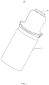
FIG. 1 is a schematic structural diagram of an atomizer in an embodiment of the present disclosure; -
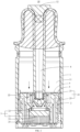
FIG. 2 is a sectional view of the atomizer in one direction in an embodiment of the present disclosure; -
FIG. 3 is a schematic structural diagram of a cover in an embodiment of the present disclosure; -
FIG. 4 is a schematic structural diagram of a cover seal in an embodiment of the present disclosure; -
FIG. 5 is a top view of the cover in an embodiment of the present disclosure; -
FIG. 6 is a sectional view of the cover in an embodiment of the present disclosure; -
FIG. 7 is a top view of the cover and the cover seal in an embodiment of the present disclosure; -
FIG. 8 is a sectional view of the cover and the cover seal in an embodiment of the present disclosure; -
FIG. 9 is a sectional view of the atomizer in another direction in an embodiment of the present disclosure; -
FIG. 10 is a schematic structural diagram of an atomizing device in an embodiment of the present disclosure; and -
FIG. 11 is a schematic diagram of the atomizing device in an embodiment of the present disclosure. - 10, atomizer; 1, shell; 11, liquid storage cavity; 12, suction nozzle; 2, cover; 21, air channel; 22, fluid channel; 23, guide groove; 24, atomizing cavity; 25, groove; 3, atomizing assembly; 31, heating element; 32, heating element seal; 33, heating wire; 4, valve; 5, cover seal; 51, through hole; 52, surrounding portion; 53, covering portion; 6, air outlet channel; 7, atomizing device; 71, power supply.
- In order to have a better understanding of the objectives, the technical solutions, and the advantages of the present disclosure, the present disclosure will be further described in detail below in conjunction with the accompanying drawings and embodiments. It should be understood that the specific embodiments described herein are only intended to explain the present disclosure and are not intended to limit the present disclosure.
- In the case of no contradiction, the various specific technical features described in the specific embodiments can be combined in any suitable manner, such as forming different embodiments and technical solutions through a combination of different specific technical features. In order to avoid unnecessary repetition, various possible combinations of specific technical features in the present disclosure will not be described separately.
- In the following description, the terms such as "first, second,..." are merely intended to distinguish between different objects, but do not indicate that the objects have similarities or connections. It should be understood that the described orientations such as "above", "below", "outside", "inside", "left", and "right" indicate the directions shown in the specific corresponding schematic diagrams, which may be or may not be the directions in a normal use state.
- It should be noted that, the terms "include", "comprise", or any other variation thereof are intended to cover non-exclusive inclusion, such that a process, a method, an item, or a device that includes a series of elements not only includes those elements, but also includes other elements that are not explicitly listed, or also includes elements inherent to such a process, a method, an item, or a device. In the absence of further limitations, the element defined by the statement " includes a..." does not exclude the existence of an additional identical element in the process, the method, the item, or the device that includes that element. The term "a plurality of" means greater than or equal to two.
- An embodiment of the disclosure provides an atomizer and an atomizing device. The atomizing device includes the atomizer, which is configured to atomize an aerosol atomizing substrate into an aerosol. The atomizer can be applied to various atomization scenarios, such as medical cosmetology, nicotine delivery, daily life or other atomization scenarios. The aerosol atomizing substrate may be a medical powder, a fragrance, a nicotine preparation, or an aerosol substrate that can produce a special odor. A person skilled in the art can understand that there are a plurality of application scenarios of the atomizer, and the application scenario of the atomizer is not limited in the embodiments of the present disclosure.
- As shown in
FIG. 1 andFIG. 2 , an embodiment of the present disclosure provides anatomizer 10, which includes ashell 1, acover 2, anatomizing assembly 3, and avalve 4. Wherein, theshell 1 is provided with aliquid storage cavity 11 for accommodating the aerosol atomizing substrate, asuction nozzle 12 is provided at the top of theshell 1 in the length direction of theatomizer 10, and a user can draw the aerosol generated after atomization through thesuction nozzle 12. Thecover 2 is arranged in theshell 1. Theatomizing assembly 3 is arranged in thecover 2 and configured to atomize the aerosol atomizing substrate to generate the aerosol, and the user can draw the aerosol generated by theatomizing assembly 3 of theatomizer 10 through thesuction nozzle 12. For example, theatomizing assembly 3 may include a heating element configured for heating and atomizing the aerosol atomizing substrate to generate the aerosol, and/or, an atomizing nozzle configured for atomizing the aerosol atomizing substrate to form atomized droplet particles and spraying them outwards. The atomizing nozzle may be, for example, a gas-liquid two-phase flow atomizing nozzle, an airflow channel and a fluid channel are provided inside the nozzle, the gas and the aerosol atomizing substrate enter the nozzle, and the gas impacts the aerosol atomizing substrate to atomize the aerosol atomizing substrate, to form atomized droplet particles and spray them into a cavity outside the atomizing nozzle for the user to suck. - As shown in
FIG. 2 andFIG. 3 , thecover 2 is provided with anair channel 21 communicating theliquid storage cavity 11 with an external atmosphere, and afluid channel 22 communicating theliquid storage cavity 11 with theatomizing assembly 3. When the aerosol atomizing substrate in theliquid storage cavity 11 enters theatomizing assembly 3 through thefluid channel 22 for atomization, a negative pressure will be formed in theliquid storage cavity 11 due to liquid outflow, and at this time, the external airflow can enter theliquid storage cavity 11 through theair channel 21 for ventilation to reduce the negative pressure, so that the pressure balance between theliquid storage cavity 11 and the external atmosphere is maintained, and the aerosol atomizing substrate in theliquid storage cavity 11 can smoothly enter theatomizing assembly 3. - As shown in
FIG. 4 to FIG. 6 , thevalve 4 is disposed at theair channel 21 to control the communication and the closure of theliquid storage cavity 11 and the external atmosphere. When the negative pressure in theliquid storage cavity 11 is relatively small, thevalve 4 closes theair channel 21 under the gravity of the aerosol atomizing substrate in theliquid storage cavity 11 to control the communication of theliquid storage cavity 11 and the external atmosphere to be closed, thereby reducing the leakage of the aerosol atomizing substrate in theliquid storage cavity 11 through theair channel 21. When thevalve 4 controls theliquid storage cavity 11 and the external atmosphere to be communicated, the external airflow can enter theliquid storage cavity 11 through theair channel 21 for ventilation to reduce the negative pressure and maintain the pressure balance between theliquid storage cavity 11 and the external atmosphere. For example, thevalve 4 can be made of a flexible material, so that thevalve 4 can be deformed under the action of an external force, for example, thevalve 4 can be blown open by the impact action of the airflow, so that theliquid storage cavity 11 is communicated with the external atmosphere. When there is no airflow passing through theair channel 21, thevalve 4 is lapped above theair channel 21, so that the communication between theliquid storage cavity 11 and the external atmosphere is closed. - As shown in
FIG. 5 , theair channel 21 has two ends, and if combined with the ventilation function, since the ventilation is directional, the inlet end is the initial end of theair channel 21, and the outlet end is the tail end of theair channel 21. In the direction towards the tail end of theair channel 21, the sectional area of the part of theair channel 21 located upstream of thevalve 4 decreases. It can be understood that, the magnitude of the reduction in the sectional area of theair channel 21 may be uniform or uneven, as long as the overall sectional areas of theair channel 21 present a decreasing trend, where the upstream refers to being closer to the source of the airflow. Thevalve 4 may be arranged at the tail end of theair channel 21 or in the middle of theair channel 21. However, the airflow first flows through the part of theair channel 21 located upstream of thevalve 4, and then flows to the part of theair channel 21 provided with thevalve 4. Thus, when the airflow enters from theair channel 21, as it flows towards the tail end of theair channel 21, the flow velocity of the airflow passing through theair channel 21 with the reduced sectional area will increase, that is, the flow velocity of the airflow passing through theair channel 21 located upstream of thevalve 4 will increase, and then the airflow flows to theair channel 21 provided with thevalve 4 at a higher speed to impact thevalve 4. - By using the lift formula L=C1 * Pv2 * S, it can be inferred that the aerodynamic velocity and the generated force are in a square relationship, and a larger force can be applied to the end of the
valve 4 more effectively by increasing the air inlet speed, making it easier to puncture the liquid film formed by the aerosol atomizing substrate to achieve the ventilation. The increase in force reduces the range requirement for the hardness, the thickness, the width, or the sectional area of thevalve 4. For example, the thickness of therelated valve 4 needs to be 0.2+0.02 mm in order to allow normal ventilation, while the thickness of thevalve 4 using the solution described in the embodiment of the present disclosure can be 0.25+0.1/0.05 mm, thereby expanding the acceptable tolerance range for the production of thevalve 4, improving the ventilation stability of thevalve 4, and improving the product performance consistency. - In the embodiment of the present disclosure, in the direction towards the tail end of the air channel, the sectional area of the part of the air channel located upstream of the valve decreases. When the airflow enters from the air channel, the airflow first flows through the part of the air channel located upstream of the valve, and since the sectional area of the air channel here is reduced, the flow velocity increases, and then the airflow flows to the part of the air channel provided with the valve to impact the valve. By increasing the inlet speed of the airflow to impact the valve, a larger force can be effectively applied to the end of the valve, so that the valve can be opened more easily, and the liquid film formed by the aerosol atomizing substrate can be punctured to achieve the ventilation. Moreover, the force exerted by the airflow on the valve increases, so that the valve is easier to be opened under the impact of the airflow, and therefore, the range requirement for the hardness, the thickness, the width, or the sectional area of the valve can be reduced in actual production, thereby expanding the acceptable tolerance range for the product production, improving the ventilation stability of the
valve 4, and improving the product performance consistency. - In some embodiments, as shown in
FIG. 3 andFIG. 5 , theair channel 21 includes aguide groove 23 located at the tail end of the airflow, and theair channel 21 further includes other parts, such as agroove 25 formed by a side wall of thecover 2. Thegroove 25 communicates theguide groove 23 with the external atmosphere, that is, thegroove 25 is arranged close to the initial end of the airflow to be communicated with the external atmosphere. Theguide groove 23 is arranged close to the tail end of the airflow to be communicated with theliquid storage cavity 11. Thegroove 25 may be set with an equal cross-section area or with a reduced sectional area. Theguide groove 23 is disposed at the top of thecover 2, and thevalve 4 covers theguide groove 23. As shown inFIG. 2 , the top of thecover 2 is close to theliquid storage cavity 11, so that theguide groove 23 is disposed close to theliquid storage cavity 11, and when the airflow flows in theguide groove 23, the ventilation with theliquid storage cavity 11 will be more direct and convenient. The sectional area of theguide groove 23 gradually decreases in the direction towards the tail end of theair channel 21, that is, the magnitude of the reduction in the sectional area of theguide groove 23 is uniform. - The air channel in the embodiment of the present disclosure includes the guide groove located at the tail end of the airflow, and the sectional area of the guide groove gradually decreases in the direction towards the tail end of the air channel, that is, the magnitude of the reduction in the sectional area of the guide groove is uniform. When the airflow flows in the guide groove, the flow velocity can be increased uniformly, so that the flow velocity of the airflow is steadily increased, thereby effectively reducing the energy loss of the airflow and enabling the valve to be opened more stably.
- In some embodiments, as shown in
FIG. 3 andFIG. 5 , the extension directions of two side walls of theguide groove 23 present an oblique angle of 1 ° to 10 °, where the oblique angle is θ as shown inFIG. 5 . Since the extension directions of the two side walls of theguide groove 23 present a certain oblique angle, the closer to the tail end of the airflow, the closer the two side walls of theguide groove 23 are, thereby reducing the sectional area of theguide groove 23 close to the tail end of the airflow in the horizontal direction. As shown inFIG. 3 , the side wall of theguide groove 23 close to thegroove 25 is inclined towards thegroove 25, so that the airflow in thegroove 25 can flow into theguide groove 23 under the guidance of the inclined side wall, making the airflow flow smoother; and/or, as shown inFIG. 6 , in the direction towards the tail end of theair channel 21, the bottom wall of theguide groove 23 is in a smooth transition and tilts towards theliquid storage cavity 11, and it can be understood that the bottom wall of theguide groove 23 may extend in a straight line or in a smooth transition curve, and at least part of the bottom wall of theguide groove 23 has a certain slope, so that it can tilt towards theliquid storage cavity 11, thereby reducing the sectional area of theguide groove 23 close to the tail end of the airflow in the vertical direction. - In the embodiments of the present disclosure, the oblique angle of the extension directions of the two side walls of the guide groove is relatively small in the direction towards the tail end of the airflow, and/or, the bottom wall of the guide groove is inclined towards the direction of the liquid storage cavity in the direction towards the tail end of the air channel. Therefore, when the airflow flows to the tail end of the airflow in the guide groove, the airflow tends to be in a point or a smaller plane, in other words, a large amount of airflow is compressed and accelerated to the tail end, so that the force formed by the airflow is easier to open the valve, and puncture the liquid film formed by the aerosol atomizing substrate to achieve the ventilation between the external atmosphere and the liquid storage cavity.
- In some embodiments, as shown in
FIG. 3 andFIG. 6 , in the direction towards the tail end of theair channel 21, the slope of the bottom wall of theguide groove 23 varies, and the slope of the bottom wall of theguide groove 23 first increases and then decreases. It can be understood that, when the airflow in thegroove 25 just enters theguide groove 23, the slope of the bottom wall of theguide groove 23 is relatively small, so that the airflow in thegroove 25 can enter theguide groove 23 smoothly. As the airflow flows towards the tail end of theair channel 21, the slope of the bottom wall of theguide groove 23 first increases, so that the sectional area of theguide groove 23 is reduced in the vertical direction, and the airflow is compressed and accelerated. As shown inFIG. 7 andFIG. 8 , the slope of the bottom wall of theguide groove 23 then decreases, so that the airflow can impact thevalve 4 located at the tail end of the airflow at a relatively high speed and flow smoothly into theliquid storage cavity 11. Moreover, the slope of the bottom wall of theguide groove 23 at the tail end of the airflow is relatively small, so that when thevalve 4 is located above theguide groove 23, it can be stably lapped above theguide groove 23, thus separating theguide groove 23 from theliquid storage cavity 11 when theatomizer 10 is not in use. - In the embodiment of the present disclosure, in the direction towards the tail end of the air channel, the slope of the bottom wall of the guide groove first increases and then decreases, that is, the slope of the bottom wall of the guide groove presents a "small, large, small" manner, so that the airflow in the groove can enter the guide groove smoothly and is accelerated in the part with a larger slope, and when flowing to the tail end of the airflow, the slope of the bottom wall of the guide groove is relatively small, so that the airflow impacts the valve located at the tail end of the airflow at a relatively high speed and can flow smoothly into the liquid storage cavity. In addition, the valve can be stably lapped above the guide groove, thereby separating the guide groove from the liquid storage cavity to reduce the liquid leakage in the liquid storage cavity when the atomizer is not in use.
- In some embodiments, as shown in
FIG. 5 andFIG. 6 , the sectional area of theguide groove 23 decreases in the direction towards the tail end of theair channel 21, so that the depth of theguide groove 23 is variable, and the depth of theguide groove 23 ranges from 0.01 mm to 0.5 mm; and/or, the width of theguide groove 23 is variable, and the width of theguide groove 23 ranges from 0.1 mm to 1.0 mm. In the embodiments of the present disclosure, the depth of the guide groove is variable, and/or, the width of the guide groove is variable, and the depth range and the width range of the guide groove are respectively defined, so that the sectional area of the tail end of the guide groove is relatively small, so that the force of the airflow is not dissipated, the force is concentrated at the end of the valve, the ventilation position is fixed, and the product consistency is improved. - In some embodiments, as shown in
FIG. 2 andFIG. 4 , theatomizer 10 further includes acover seal 5 disposed on the outer surface of thecover 2 to seal theliquid storage cavity 11. Thecover seal 5 may be made of a material with better sealing performance, such as silicone. The top wall of thecover seal 5 adjacent to theliquid storage cavity 11 is provided with a throughhole 51 to communicate theliquid storage cavity 11 with thefluid channel 22, so that the aerosol atomizing substrate in theliquid storage cavity 11 can enter thefluid channel 22 through the throughhole 51. Theair channel 21 is disposed between thecover seal 5 and thecover 2 and communicates the external atmosphere with theliquid storage cavity 11, and thecover seal 5 does not seal the inlet end and the outlet end of theair channel 21. Theair channel 21 is provided with thevalve 4, and thevalve 4 may be an independent component, or may be a part of thecover seal 5. The atomizer in the embodiment of the present disclosure further includes the cover seal disposed on the outer surface of the cover to seal the liquid storage cavity, thereby reducing the leakage of the aerosol atomizing substrate in the liquid storage cavity through a gap between the cover and the shell, and improving the user experience. - In some embodiments, as shown in
FIG. 4 andFIG. 7 , thecover seal 5 includes a surroundingportion 52 and a coveringportion 53. Wherein, the surroundingportion 52 is arranged around a side wall of thecover 2 to seal a gap between the side wall of thecover 2 and theshell 1, thereby reducing the leakage of the aerosol atomizing substrate in theliquid storage cavity 11 through the gap between the side wall of thecover 2 and theshell 1. A part of the air channel 21 (the groove 25) is formed between the side wall of thecover 2 and the surroundingportion 52. The coveringportion 53 is connected to one end of the surroundingportion 52 and covers the top of thecover 2. Theguide groove 23 is arranged at the top of thecover 2, the coveringportion 53 is provided with the throughhole 51, and theguide groove 23 is communicated with theliquid storage cavity 11 through the throughhole 51. One end of thevalve 4 is connected to the surroundingportion 52, and the other end of thevalve 4 is a free end. Thevalve 4 covers above theguide groove 23, and the other end (the free end) of thevalve 4 can open and close theair channel 21 under the action of the airflow in theair channel 21. When the airflow flows in theguide groove 23, as the flow velocity of the airflow increases, the force exerted by the airflow on thevalve 4 increases, so that thevalve 4 is opened under the impact of the airflow for ventilation. When theatomizer 10 is not in use, there is no airflow flowing in theguide groove 23, thevalve 4 covers above theguide groove 23 to close theair channel 21, thereby reducing the leakage of the aerosol atomizing substrate in theliquid storage cavity 11 when theatomizer 10 is not in use. - The cover seal in the embodiment of the present disclosure includes the surrounding portion and the covering portion, the surrounding portion is arranged around the side wall of the cover, and the covering portion covers the top of the cover, thereby reducing the leakage of the aerosol atomizing substrate in the liquid storage cavity through the gap between the side wall of the cover and the shell and the gap of the cover itself. One end of the valve is connected to the surrounding portion, so that the valve and the surrounding portion can be integrated as a whole during actual design and production, thereby facilitating actual production and installation. The valve serves as a part of the cover seal, so that the cover seal not only plays a role in sealing the liquid storage cavity, but also serves as a the valve for opening and closing the air channel, and the functions are diversified.
- In some embodiments, as shown in
FIG. 5 andFIG. 7 , the sectional area of thevalve 4 gradually decreases in the direction towards the tail end of theair channel 21. That is to say, as the sectional area of theguide groove 23 gradually decreases, the sectional area of thevalve 4 gradually decreases correspondingly. In the embodiment of the present disclosure, the sectional area of the valve gradually decreases in the direction towards the tail end of the air channel, so that the force required for the airflow to open the valve is smaller, making it easier for the airflow to impact and open the valve, thereby achieving the ventilation between the external atmosphere and the liquid storage cavity. - In some embodiments, as shown in
FIG. 2 andFIG. 9 , the cross sections shown inFIG. 2 andFIG. 9 are two cross sections perpendicular to each other of the atomizer, and the arrow directions shown inFIG. 2 andFIG. 9 refer to the airflow flow direction and the liquid flow direction ofatomizer 10. Thecover 2 is provided with anatomizing cavity 24 therein. Theatomizing assembly 3 includes aheating element 31 and aheating element seal 32. Wherein, the aerosol atomizing substrate in theliquid storage cavity 11 flows to theheating element 31 through thefluid channel 22. For example, theheating element 31 may be a porous ceramic heating element, which can absorb and store the aerosol atomizing substrate. Theheating element 31 is disposed in theatomizing cavity 24 and is configured to heat the aerosol atomizing substrate to generate the aerosol. Theheating element seal 32 is disposed at the top of theheating element 31 to isolate thefluid channel 22 from theatomizing cavity 24, so that when the aerosol atomizing substrate in theliquid storage cavity 11 flows to theheating element 31 through thefluid channel 22, it is not easy to directly leak into theatomizing cavity 24. Theheating element seal 32 may be made of a material with good sealing performance, such as silicone. Theatomizing cavity 24 is not in direct communication with thefluid channel 22, but is indirectly communicated with thefluid channel 22 through theheating element 31. Theheating element 31 absorbs and stores the aerosol atomizing substrate flowing from thefluid channel 22, heats and atomizes the aerosol atomizing substrate into the aerosol, and then emits the aerosol into theatomizing cavity 24. Aheating wire 33 of theheating element 31 is distributed on the side of theheating element 31 away from thefluid channel 22, that is, distributed at the bottom of theheating element 31, so that a liquid absorbing surface and a heating surface of theheating element 31 can be separated to a certain extent, and most of the aerosol atomizing substrate is atomized on the bottom side of theheating element 31 and dispersed into theatomizing cavity 24, and the atomization effect is good. Theatomizer 10 is further provided with anair outlet channel 6 through which the aerosol flows out, and theatomizing cavity 24 is in communication with theair outlet channel 6. The aerosol is emitted into theatomizing cavity 24 and then flows out through theair outlet channel 6 for the user to absorb. - The atomizing assembly in the embodiment of the present disclosure includes the heating element and the heating element seal. The aerosol atomizing substrate is heated and atomized into the aerosol through the heating element. Since no combustion is needed, the generation of harmful substances such as tar and suspended particles is reduced to a certain extent. The heating element seal isolates the fluid channel from the atomizing cavity. The aerosol atomizing substrate flowing into the fluid channel needs to be heated and atomized by the heating element to form the aerosol, and then the aerosol is dispersed into the atomizing cavity to achieve gas-liquid separation, so that the aerosol is more delicate and the user experience is better when the user sucks.
- As shown in
FIG. 10 andFIG. 11 , anatomizing device 7 is provided in an embodiment of the present disclosure, including theatomizer 10 and apower supply 71. Wherein, thepower supply 71 is configured to supply power to theatomizer 10. For example, thepower supply 71 is electrically connected to theheating element 31 of theatomizer 10, so that when thepower supply 71 is turned on, theheating element 31 of theatomizer 10 is energized to generate heat, so as to heat and atomize the aerosol atomizing substrate to generate the aerosol. The atomizing device in the embodiment of the present disclosure includes the atomizer and the power supply configured to supply power to the atomizer, and the turning on and off of the atomizer can be controlled by controlling the power supply. For example, the power supply may be a visual button for the user, so that the user can control the turning on and off of the atomizer by controlling the button, thereby facilitating the use of the user. - The above descriptions are merely preferred embodiments of the present disclosure and are not intended to limit the protection scope of the present disclosure.
- While the disclosure has been illustrated and described in detail in the drawings and foregoing description, such illustration and description are to be considered illustrative or exemplary and not restrictive. It will be understood that changes and modifications may be made by those of ordinary skill within the scope of the following claims. In particular, the present disclosure covers further embodiments with any combination of features from different embodiments described above and below. Additionally, statements made herein characterizing the disclosure refer to an embodiment of the disclosure and not necessarily all embodiments.
- The terms used in the claims should be construed to have the broadest reasonable interpretation consistent with the foregoing description. For example, the use of the article "a" or "the" in introducing an element should not be interpreted as being exclusive of a plurality of elements. Likewise, the recitation of "or" should be interpreted as being inclusive, such that the recitation of "A or B" is not exclusive of "A and B," unless it is clear from the context or the foregoing description that only one of A and B is intended. Further, the recitation of "at least one of A, B and C" should be interpreted as one or more of a group of elements consisting of A, B and C, and should not be interpreted as requiring at least one of each of the listed elements A, B and C, regardless of whether A, B and C are related as categories or otherwise. Moreover, the recitation of "A, B and/or C" or "at least one of A, B or C" should be interpreted as including any singular entity from the listed elements, e.g., A, any subset from the listed elements, e.g., A and B, or the entire list of elements A, B and C.
Claims (15)
- An atomizer, comprising:a shell provided with a liquid storage cavity configured for accommodating an aerosol atomizing substrate;a cover arranged in the shell;an atomizing assembly arranged in the cover and configured to atomize the aerosol atomizing substrate to generate an aerosol; anda valve,wherein the cover is provided with an air channel communicating the liquid storage cavity with an external atmosphere and a fluid channel communicating the liquid storage cavity with the atomizing assembly,wherein the air channel is provided with the valve for controlling a communication and a cutoff between the liquid storage cavity and the external atmosphere, andwherein a sectional area of a part of the air channel located upstream of the valve decreases in a direction towards a tail end of the air channel.
- The atomizer of claim 1, wherein the air channel comprises a guide groove located at a tail end of an airflow and disposed at a top of the cover,wherein the valve covers the guide groove, andwherein a sectional area of the guide groove gradually decreases in the direction towards the tail end of the air channel.
- The atomizer of claim 2, wherein extension directions of two side walls of the guide groove present an oblique angle.
- The atomizer of claim 3, wherein the oblique angle ranges from 1 ° to 10 °.
- The atomizer of claim 3, wherein the air channel comprises a groove formed on a side wall of the cover and communicating the guide groove with the external atmosphere, and
wherein a side wall of the guide groove close to the groove is inclined towards the groove. - The atomizer of claim 2, wherein a bottom wall of the guide groove is inclined towards the liquid storage cavity in the direction towards the tail end of the air channel.
- The atomizer of claim 6, wherein in the direction towards the tail end of the air channel, a slope of the bottom wall of the guide groove first increases and then decreases.
- The atomizer of claim 2, wherein a depth of the guide groove ranges from 0.01 mm to 0.5 mm.
- The atomizer of claim 2, wherein a width of the guide groove ranges from 0.1 mm to 1.0 mm.
- The atomizer of claim 2, further comprising:a cover seal disposed on an outer surface of the cover to seal the liquid storage cavity,wherein a top wall of the cover seal adjacent to the liquid storage cavity is provided with a through hole communicating the liquid storage cavity with the fluid channel, andwherein the air channel is provided between the cover seal and the cover.
- The atomizer of claim 10, wherein the cover seal comprises:a surrounding portion surrounding a side wall of the cover to seal a gap between the side wall of the cover and the shell, the air channel being partly formed between the side wall of the cover and the surrounding portion; anda covering portion connected to one end of the surrounding portion and covering the top of the cover,wherein the covering portion is provided with the through hole,wherein one end of the valve is connected to the surrounding portion, and another end of the valve is a free end,wherein the valve covers above the guide groove, andwherein the another end of the valve is able to open and close the air channel under an action of a gas in the air channel.
- The atomizer of claim 11, wherein a sectional area of the valve gradually decreases in the direction towards the tail end of the air channel.
- The atomizer of claim 11, wherein the valve is integrally formed with the cover seal.
- The atomizer of claim 1, wherein an atomizing cavity is provided in the cover,
wherein the atomizing assembly comprises:a heating element disposed in the atomizing cavity and configured to heat the aerosol atomizing substrate to generate the aerosol; anda heating element seal disposed at a top of the heating element to isolate the fluid channel from the atomizing cavity,wherein the atomizer is provided with an air outlet channel for the aerosol to flow out, and the atomizing cavity is in communication with the air outlet channel. - An atomizing device, comprising:the atomizer of any one of claims 1 to 14; anda power supply configured to supply power to the atomizer.
Applications Claiming Priority (1)
| Application Number | Priority Date | Filing Date | Title |
|---|---|---|---|
| CN202322111112.1U CN220756584U (en) | 2023-08-07 | 2023-08-07 | Atomizer and atomizing device |
Publications (2)
| Publication Number | Publication Date |
|---|---|
| EP4505892A1 true EP4505892A1 (en) | 2025-02-12 |
| EP4505892B1 EP4505892B1 (en) | 2025-12-31 |
Family
ID=90612072
Family Applications (1)
| Application Number | Title | Priority Date | Filing Date |
|---|---|---|---|
| EP24191630.3A Active EP4505892B1 (en) | 2023-08-07 | 2024-07-30 | Atomizer and atomizing device |
Country Status (2)
| Country | Link |
|---|---|
| EP (1) | EP4505892B1 (en) |
| CN (1) | CN220756584U (en) |
Citations (3)
| Publication number | Priority date | Publication date | Assignee | Title |
|---|---|---|---|---|
| CN215381464U (en) * | 2021-06-03 | 2022-01-04 | 比亚迪精密制造有限公司 | Electronic cigarette cartridges and electronic cigarettes |
| WO2022111358A1 (en) * | 2020-11-25 | 2022-06-02 | 深圳市合元科技有限公司 | Atomiser and electronic atomising apparatus |
| US20220248765A1 (en) * | 2020-05-29 | 2022-08-11 | Shenzhen Smoore Technology Limited | Atomizer and electronic atomizing device |
-
2023
- 2023-08-07 CN CN202322111112.1U patent/CN220756584U/en active Active
-
2024
- 2024-07-30 EP EP24191630.3A patent/EP4505892B1/en active Active
Patent Citations (3)
| Publication number | Priority date | Publication date | Assignee | Title |
|---|---|---|---|---|
| US20220248765A1 (en) * | 2020-05-29 | 2022-08-11 | Shenzhen Smoore Technology Limited | Atomizer and electronic atomizing device |
| WO2022111358A1 (en) * | 2020-11-25 | 2022-06-02 | 深圳市合元科技有限公司 | Atomiser and electronic atomising apparatus |
| CN215381464U (en) * | 2021-06-03 | 2022-01-04 | 比亚迪精密制造有限公司 | Electronic cigarette cartridges and electronic cigarettes |
Also Published As
| Publication number | Publication date |
|---|---|
| EP4505892B1 (en) | 2025-12-31 |
| CN220756584U (en) | 2024-04-12 |
Similar Documents
| Publication | Publication Date | Title |
|---|---|---|
| US11040362B2 (en) | Atomizing nozzle and atomizing device comprising same | |
| DK151045B (en) | SUSPENSION VALUES FOR DELIVERING A UNDERPRESSED LIQUID BASKET | |
| US20250057244A1 (en) | Atomizer and electronic atomizing device | |
| JPS6064660A (en) | Spray discharge apparatus for deformable container | |
| KR20230026937A (en) | Electronic atomization device | |
| WO2023125068A1 (en) | Cartridge for electronic cigarettes and electronic cigarette | |
| EP4505892B1 (en) | Atomizer and atomizing device | |
| CN108435451A (en) | A kind of automatic spray gun | |
| EP4218436B1 (en) | Atomization core, atomizer, and electronic atomization apparatus | |
| CN114747810B (en) | Atomizer and electronic atomization device | |
| CN221044284U (en) | Atomizer and atomizing device | |
| CN217885087U (en) | Double-station atomizing device | |
| CN115777994B (en) | Atomizer and electronic atomization device | |
| CN208177707U (en) | A kind of atomizer | |
| CN209347833U (en) | A kind of atomising device | |
| CN224069730U (en) | Atomizer and atomizing equipment | |
| CN207287822U (en) | A kind of twin fluid atomization device | |
| CN221902382U (en) | Liquid leakage prevention control device and aerosol generating device with same | |
| CN220174481U (en) | Atomizing base, atomizer and aerosol generating device | |
| CN216961506U (en) | Cartridges and Electronic Cigarettes for Electronic Cigarettes | |
| CN224179161U (en) | Liquid reservoir and its atomizing device | |
| CN223174727U (en) | Sealing assembly, mist outlet structure and atomization assembly | |
| CN223365000U (en) | Atomizing core assembly and atomizer | |
| CN224165696U (en) | Electronic atomizing device | |
| CN218418406U (en) | Electronic atomization device |
Legal Events
| Date | Code | Title | Description |
|---|---|---|---|
| PUAI | Public reference made under article 153(3) epc to a published international application that has entered the european phase |
Free format text: ORIGINAL CODE: 0009012 |
|
| STAA | Information on the status of an ep patent application or granted ep patent |
Free format text: STATUS: THE APPLICATION HAS BEEN PUBLISHED |
|
| AK | Designated contracting states |
Kind code of ref document: A1 Designated state(s): AL AT BE BG CH CY CZ DE DK EE ES FI FR GB GR HR HU IE IS IT LI LT LU LV MC ME MK MT NL NO PL PT RO RS SE SI SK SM TR |
|
| STAA | Information on the status of an ep patent application or granted ep patent |
Free format text: STATUS: REQUEST FOR EXAMINATION WAS MADE |
|
| 17P | Request for examination filed |
Effective date: 20250410 |
|
| RAP3 | Party data changed (applicant data changed or rights of an application transferred) |
Owner name: SHENZHEN SMOORE TECHNOLOGY LIMITED |
|
| GRAP | Despatch of communication of intention to grant a patent |
Free format text: ORIGINAL CODE: EPIDOSNIGR1 |
|
| STAA | Information on the status of an ep patent application or granted ep patent |
Free format text: STATUS: GRANT OF PATENT IS INTENDED |
|
| INTG | Intention to grant announced |
Effective date: 20251009 |
|
| GRAS | Grant fee paid |
Free format text: ORIGINAL CODE: EPIDOSNIGR3 |
|
| GRAA | (expected) grant |
Free format text: ORIGINAL CODE: 0009210 |
|
| STAA | Information on the status of an ep patent application or granted ep patent |
Free format text: STATUS: THE PATENT HAS BEEN GRANTED |
|
| AK | Designated contracting states |
Kind code of ref document: B1 Designated state(s): AL AT BE BG CH CY CZ DE DK EE ES FI FR GB GR HR HU IE IS IT LI LT LU LV MC ME MK MT NL NO PL PT RO RS SE SI SK SM TR |
|
| REG | Reference to a national code |
Ref country code: CH Ref legal event code: F10 Free format text: ST27 STATUS EVENT CODE: U-0-0-F10-F00 (AS PROVIDED BY THE NATIONAL OFFICE) Effective date: 20251231 Ref country code: GB Ref legal event code: FG4D |
|
| P01 | Opt-out of the competence of the unified patent court (upc) registered |
Free format text: CASE NUMBER: UPC_APP_0014592_4505892/2025 Effective date: 20251125 |
|
| REG | Reference to a national code |
Ref country code: DE Ref legal event code: R096 Ref document number: 602024001925 Country of ref document: DE |
|
| REG | Reference to a national code |
Ref country code: IE Ref legal event code: FG4D |
|
| REG | Reference to a national code |
Ref country code: LT Ref legal event code: MG9D |
|
| PG25 | Lapsed in a contracting state [announced via postgrant information from national office to epo] |
Ref country code: NO Free format text: LAPSE BECAUSE OF FAILURE TO SUBMIT A TRANSLATION OF THE DESCRIPTION OR TO PAY THE FEE WITHIN THE PRESCRIBED TIME-LIMIT Effective date: 20260331 |
|
| PG25 | Lapsed in a contracting state [announced via postgrant information from national office to epo] |
Ref country code: FI Free format text: LAPSE BECAUSE OF FAILURE TO SUBMIT A TRANSLATION OF THE DESCRIPTION OR TO PAY THE FEE WITHIN THE PRESCRIBED TIME-LIMIT Effective date: 20251231 Ref country code: HR Free format text: LAPSE BECAUSE OF FAILURE TO SUBMIT A TRANSLATION OF THE DESCRIPTION OR TO PAY THE FEE WITHIN THE PRESCRIBED TIME-LIMIT Effective date: 20251231 |
|
| PG25 | Lapsed in a contracting state [announced via postgrant information from national office to epo] |
Ref country code: RS Free format text: LAPSE BECAUSE OF FAILURE TO SUBMIT A TRANSLATION OF THE DESCRIPTION OR TO PAY THE FEE WITHIN THE PRESCRIBED TIME-LIMIT Effective date: 20260331 |
|
| PG25 | Lapsed in a contracting state [announced via postgrant information from national office to epo] |
Ref country code: LV Free format text: LAPSE BECAUSE OF FAILURE TO SUBMIT A TRANSLATION OF THE DESCRIPTION OR TO PAY THE FEE WITHIN THE PRESCRIBED TIME-LIMIT Effective date: 20251231 |
|
| PG25 | Lapsed in a contracting state [announced via postgrant information from national office to epo] |
Ref country code: BG Free format text: LAPSE BECAUSE OF FAILURE TO SUBMIT A TRANSLATION OF THE DESCRIPTION OR TO PAY THE FEE WITHIN THE PRESCRIBED TIME-LIMIT Effective date: 20251231 |
|
| REG | Reference to a national code |
Ref country code: NL Ref legal event code: MP Effective date: 20251231 |